1
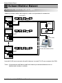
External Wiring Diagram
External Wiring Diagram
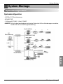
Multi-V PLUS & MPS Product
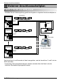
- Refer the wiring diagram and make the connections accordingly
Indoor units
Main PCB
PI 485
00
01
02
0F
A A
B B
E E
F F
C C
D D
GND GND
VCC VCC
Cross
cable
Outdoor unit 0
BUS A
Main PCB
10
11
12
1F
BUS B
LAN Port
PI 485
A A
B B
E E
F F
C C
D D
GND GND
VCC VCC
CNU
(PQNFG14B0)
Outdoor unit 1
Main PCB
PI 485
F0
F1
F2
FF
PC Central controller
A A
B B
E E
F F
C C
D D
GND GND
VCC VCC
Outdoor unit 16
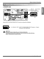
A & B terminals are connected to indoor units and C & D terminals are connected to CNU.
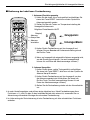
* Notice : Indoor unit address setting can be done by wired or wireless remote controller
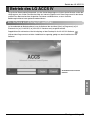
4 PC Central Controller