1
Remotizzatore GSM con I/O e linea seriale - da guida DIN
GSM repeater with I/O and serial line - DIN Rail
Dispositif de contrôle à distance GSM avec I/O et ligne série - sur rail DIN
Indicador remoto GSM con I/O y línea de serie - de guía DIN
GSM-Fernsteuerung mit I/O und serieller Linie - für DIN-Hutschiene
GW 90 821
INDICE
AVVERTENZE GENERALI
Contenuto della confezione . . . . . . . . . . . . . . . . . . . . . . . . . . . . . . . . . . . . . . . . . . . . . . . . . . . . . . . . . . . . . . . . . . . . . . . . . . . .4
DESCRIZIONE GENERALE
In breve . . . . . . . . . . . . . . . . . . . . . . . . . . . . . . . . . . . . . . . . . . . . . . . . . . . . . . . . . . . . . . . . . . . . . . . . . . . . . . . . . . . . . . . . . . .5
Funzioni . . . . . . . . . . . . . . . . . . . . . . . . . . . . . . . . . . . . . . . . . . . . . . . . . . . . . . . . . . . . . . . . . . . . . . . . . . . . . . . . . . . . . . . . . . .6
INSTALLAZIONE
Avvertenze per l’installazione . . . . . . . . . . . . . . . . . . . . . . . . . . . . . . . . . . . . . . . . . . . . . . . . . . . . . . . . . . . . . . . . . . . . . . . . . . .8
Verifica della copertura GSM . . . . . . . . . . . . . . . . . . . . . . . . . . . . . . . . . . . . . . . . . . . . . . . . . . . . . . . . . . . . . . . . . . . . . . . . . . .8
SIM . . . . . . . . . . . . . . . . . . . . . . . . . . . . . . . . . . . . . . . . . . . . . . . . . . . . . . . . . . . . . . . . . . . . . . . . . . . . . . . . . . . . . . . . . . . . . .8
Montaggio su guida DIN . . . . . . . . . . . . . . . . . . . . . . . . . . . . . . . . . . . . . . . . . . . . . . . . . . . . . . . . . . . . . . . . . . . . . . . . . . . . . . .9
Connessioni elettriche . . . . . . . . . . . . . . . . . . . . . . . . . . . . . . . . . . . . . . . . . . . . . . . . . . . . . . . . . . . . . . . . . . . . . . . . . . . . . . .11
Connessioni seriali . . . . . . . . . . . . . . . . . . . . . . . . . . . . . . . . . . . . . . . . . . . . . . . . . . . . . . . . . . . . . . . . . . . . . . . . . . . . . . . . . .12
Connessioni interfacce . . . . . . . . . . . . . . . . . . . . . . . . . . . . . . . . . . . . . . . . . . . . . . . . . . . . . . . . . . . . . . . . . . . . . . . . . . . . . . .14
Inserimento SIM . . . . . . . . . . . . . . . . . . . . . . . . . . . . . . . . . . . . . . . . . . . . . . . . . . . . . . . . . . . . . . . . . . . . . . . . . . . . . . . . . . . .16
Posizionamento e connessione antenna . . . . . . . . . . . . . . . . . . . . . . . . . . . . . . . . . . . . . . . . . . . . . . . . . . . . . . . . . . . . . . . . . .17
Messa in servizio . . . . . . . . . . . . . . . . . . . . . . . . . . . . . . . . . . . . . . . . . . . . . . . . . . . . . . . . . . . . . . . . . . . . . . . . . . . . . . . . . . .17
PROGRAMMAZIONE
Modalità di configurazione . . . . . . . . . . . . . . . . . . . . . . . . . . . . . . . . . . . . . . . . . . . . . . . . . . . . . . . . . . . . . . . . . . . . . . . . . . . .18
Password . . . . . . . . . . . . . . . . . . . . . . . . . . . . . . . . . . . . . . . . . . . . . . . . . . . . . . . . . . . . . . . . . . . . . . . . . . . . . . . . . . . . . . . . .18
Configurazione con PC . . . . . . . . . . . . . . . . . . . . . . . . . . . . . . . . . . . . . . . . . . . . . . . . . . . . . . . . . . . . . . . . . . . . . . . . . . . . . . .18
Interazione e configurazione via SMS . . . . . . . . . . . . . . . . . . . . . . . . . . . . . . . . . . . . . . . . . . . . . . . . . . . . . . . . . . . . . . . . . . . .19
Configurazione di base . . . . . . . . . . . . . . . . . . . . . . . . . . . . . . . . . . . . . . . . . . . . . . . . . . . . . . . . . . . . . . . . . . . . . . . . . . . . . . .20
Configurazioni via SMS . . . . . . . . . . . . . . . . . . . . . . . . . . . . . . . . . . . . . . . . . . . . . . . . . . . . . . . . . . . . . . . . . . . . . . . . . . . . . .20
Collaudo . . . . . . . . . . . . . . . . . . . . . . . . . . . . . . . . . . . . . . . . . . . . . . . . . . . . . . . . . . . . . . . . . . . . . . . . . . . . . . . . . . . . . . . . . .23
IN SERVIZIO
Gestione da remoto via SMS . . . . . . . . . . . . . . . . . . . . . . . . . . . . . . . . . . . . . . . . . . . . . . . . . . . . . . . . . . . . . . . . . . . . . . . . . .24
Indicazioni locali . . . . . . . . . . . . . . . . . . . . . . . . . . . . . . . . . . . . . . . . . . . . . . . . . . . . . . . . . . . . . . . . . . . . . . . . . . . . . . . . . . . .25
Comandi locali . . . . . . . . . . . . . . . . . . . . . . . . . . . . . . . . . . . . . . . . . . . . . . . . . . . . . . . . . . . . . . . . . . . . . . . . . . . . . . . . . . . . .26
Funzionamento in caso di blackout . . . . . . . . . . . . . . . . . . . . . . . . . . . . . . . . . . . . . . . . . . . . . . . . . . . . . . . . . . . . . . . . . . . . . .26
Pulizia del remotizzatore . . . . . . . . . . . . . . . . . . . . . . . . . . . . . . . . . . . . . . . . . . . . . . . . . . . . . . . . . . . . . . . . . . . . . . . . . . . . .26
Sostituzione batterie . . . . . . . . . . . . . . . . . . . . . . . . . . . . . . . . . . . . . . . . . . . . . . . . . . . . . . . . . . . . . . . . . . . . . . . . . . . . . . . .26
Ricarica SIM . . . . . . . . . . . . . . . . . . . . . . . . . . . . . . . . . . . . . . . . . . . . . . . . . . . . . . . . . . . . . . . . . . . . . . . . . . . . . . . . . . . . . . .26
Valori preimpostati . . . . . . . . . . . . . . . . . . . . . . . . . . . . . . . . . . . . . . . . . . . . . . . . . . . . . . . . . . . . . . . . . . . . . . . . . . . . . . . . . .27
DATI TECNICI . . . . . . . . . . . . . . . . . . . . . . . . . . . . . . . . . . . . . . . . . . . . . . . . . . . . . . . . . . . . . . . . . . . . . . . . . . . .28
Valori preimpostati . . . . . . . . . . . . . . . . . . . . . . . . . . . . . . . . . . . . . . . . . . . . . . . . . . . . . . . . . . . . . . . . . . . . . . . . . . . . . . . . . .28
3
I
T
A
L
I
A
N
O
AVVERTENZE GENERALI
Attenzione! La sicurezza dell’apparecchio è garantita solo attendendosi alle istruzioni qui riportate. Pertanto è necessario leggerle
e conservarle. I prodotti Chorus devono essere installati conformemente a quanto previsto dalla norma CEI 64-8 per gli apparecchi
per uso domestico e similare, in ambienti non polverosi e dove non sia necessaria una protezione speciale contro la penetrazione di
acqua.
L’organizzazione di vendita GEWISS è a disposizione per chiarimenti e informazioni tecniche.
Gewiss SpA si riserva il diritto di apportare modifiche al prodotto descritto in questo manuale in qualsiasi momento e senza alcun
preavviso.
Contenuto della confezione
n. 1 Remotizzatore GSM con I/O e linea seriale - da guida DIN
n. 1 Antenna
n. 1 Cavo prolunga per antenna 1,5 m
n. 2 Strisce biadesive
n. 1 Manuale di installazione e uso
4
DESCRIZIONE GENERALE
In breve
Il Remotizzatore GSM con I/O e linea seriale - da guida DIN consente di comandare direttamente da remoto, con un telefono cellulare
attraverso messaggi SMS, dei carichi elettrici tramite due relè con contatti privi di potenziale e di ricevere sul telefono segnalazioni
di stato o allarme da due ingressi digitali. I comandi per i relè possono essere di tipo bistabile, temporizzati o impulsivi; gli ingressi
sono in grado di rilevare sia uno stato sia un cambiamento di fronte.
La connessione per linea seriale di cui è dotato il remotizzatore permette di gestire un programmatore elettronico (ad esempio
GW 14 581) o un cronotermostato (ad esempio GW 14 701, GW 10 703, GW 14 841). Da remoto si può pertanto gestire, ad esempio,
il programma di attivazione/disattivazione del programmatore elettronico, oppure impostare la modalità di funzionamento dell’impianto
di termoregolazione e richiedere i suoi parametri di funzionamento e la temperatura ambientale.
Attraverso le opportune interfacce è inoltre possibile interagire da remoto con i seguenti sistemi Gewiss:
• antifurto RF, per inserire totalmente o parzialmente l’impianto, disinserirlo e conoscerne lo stato, oltre a ricevere in automatico le
segnalazioni di allarme antifurto, manomissione, anomalia e panico;
• comando e controllo RF, attivare o disattivare dei carichi collegati ai moduli attuatori RF, ricevere delle segnalazioni da trasmettitori
come pulsantiere, sensori e telecomandi o comandare e richiedere lo stato di un cronotermostato RF bidirezionale;
Il remotizzatore è dotato di batterie di back-up ricaricabili per alimentarlo in caso di mancanza di tensione di rete: è così sempre
possibile segnalare la presenza di un blackout oppure inviare segnali di allarme, anomalia o manomissione dell’impianto antifurto RF.
La personalizzazione del remotizzatore viene effettuata con un PC collegato al dispositivo attraverso la porta USB, usando il software
di configurazione, oppure mediante invio di codici tramite SMS.
Il remotizzatore viene montato su guida DIN da 35 mm, all’interno di quadri elettrici o scatole di derivazione.
13
1
2
12
3
4
5
6
7
11
8
10
9
14
8
7
9
10
11
12
13
14
1
2
3
4
5
6
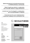
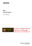
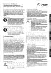
5
Alimentazione 230 V ac
Linea seriale
Ingresso 1
Ingresso 2
Uscita relè 1
Uscita relè 2
LED di segnalazione stato dispositivo
LED multifunzione di segnalazione stato
modulo GSM
Connettore per collegamento interfaccia
remotizzatore GSM - RF antifurto
Pulsante commutazione uscita relè
Porta USB (tipo B)
Collegamento antenna esterna
Cassettino per SIM
Connettore per collegamento interfaccia
remotizzatore GSM - RF comando e controllo
I
T
A
L
I
A
N
O
DESCRIZIONE GENERALE
Funzioni
FUNZIONI GESTIBILI
Commutazione uscita relè
Commutazione temporizzata uscita a relè
Commutazione impulsiva uscita a relè
■ (1) (2)
■
■
■
■
■
■
■
■ (3)
■
■
■
■
Invio SMS su ricezione “OFF”
Invio SMS su ricezione “ON” e “OFF”
Invio SMS solo su richiesta
Impostazione tipo di funzionamento cronotermostato
(riscaldamento/ condizionamento)
■
Impostazione modalità di funzionamento impianto
di termoregolazione (Manuale /automatico /off)
■
Impostazione set point manuale
■
■
Richiesta di stato cronotermostato
Con antifurto RF
e interfaccia
(GW 90 823)
■
■ (5)
Comando motore (es. tapparelle)
Invio SMS su ricezione “ON”
Con dispositivi RF
e interfaccia
(GW 90 822)
Con programmatore
elettronico e
collegamento seriale
Con cronotermostato
e collegamento
seriale
Con ingressi
e uscite interne
La tabella che segue elenca le funzioni gestibili attraverso il remotizzatore, direttamente o con l’ausilio di altri dispositivi Gewiss.
■ (3)
■ (3)
■ (3)
■
■
■
■
Attivazione modalità manuale con uscita ON
Attivazione modalità manuale con uscita OFF
Attivazione modalità AUTO
Richiesta di stato programmatore elettronico
■
■
■
■
■
■ (4)
Inserimento totale impianto allarme
Inserimento parziale impianto allarme (zona 1)
Inserimento parziale impianto allarme (zona 2)
Disinserimento impianto antifurto
Richiesta di stato impianto antifurto
Segnalazione di allarme
(1) I relè d’uscita sono bistabili, quindi al termine di un blackout mantengono lo stato precedentemente impostato.
Se i relè di uscita sono configurati come temporizzati al termine del blackout si aprono.
(2) È possibile aprire i contatti dei relè locali premendo il pulsante frontale del remotizzatore.
(3) Con il cronotermostato RF bidirezionale da parete (GW 10 851 - GW 14 851).
(4) Segnalazione inviata in automatico in caso di evento allarme antifurto, evento manomissione, evento anomalia e allarme panico.
(5) La temporizzazione viene conteggiata dall'attuatore RF e non dal remotizzatore. Al termine di un blackout il relè torna nello stato
OFF.
6
DESCRIZIONE GENERALE
MESSAGGI INVIATI DAL REMOTIZZATORE
▲
▲
▲
▲
▲
▲
■
■
Testo
personalizzabile
Invio a n. telefono
predefiniti
■
■
■
■
■
■
Testo predefinito
Invio a n. telefono
chiamanti
Il remotizzatore invia - a seguito di una richiesta diretta, come riscontro di un ordine ricevuto o come segnalazione di un evento
occorso - dei messaggi con le seguenti modalità:
Conferma di esecuzione di comando successiva all’invio di una richiesta
Commutazione relè interno
Commutazione relè dispositivo RF
Comando motore
Impostazione tipo di funzionamento cronotermostato
Impostazione modalità di funzionamento cronotermostato
Impostazione modalità di funzionamento del programmatore elettronico
Inserimento/disinserimento impianto antifurto
Attivazione/disattivazione notifica di inserimento/disinserimento
■
■
■
■
■
■
■
■
Segnalazioni di stato inviate automaticamente
■
■
■
Variazione stato ingresso locale
Variazione stato ingresso dispositivo RF
Segnalazione di allarme dell’impianto antifurto
■
■
■
Segnalazione di stato in risposta ad una richiesta
■
■
■
■
Richiesta di stato per tutti i dispositivi gestiti
Richiesta di stato per gli I/O locali e i sottosistemi RF
Richiesta di stato per i cronotermostati (1)
Richiesta di stato per il programmatore elettronico (2)
Richiesta di stato per l’impianto antifurto (3)
▲
▲
▲
▲
■
■
■
■
■
■
▲ La risposta viene inviata al numero di telefono predefinito se il numero di telefono chiamante è nascosto.
(1) La risposta include tipo e modalità di funzionamento attuale, set point di temperatura attualmente impostato, temperatura ambiente
e stato dell’attuatore (ON/OFF), tranne che per i cronotermostati RF dove viene comunicato il comando inviato perchè l’attuatore
non invia il riscontro al comando.
(2) La risposta include modalità di funzionamento e stato del contatto.
(3) La risposta include stato dell’impianto (inserito/disinserito), stato della centrale (pronta/non pronta all’inserimento), memoria di
allarme, memoria di manomissione, memoria di anomalia e lo stato della notifica di inserimento/disinserimento dell’impianto
antifurto.
Gli SMS di conferma dell’esecuzione di un comando e quelli di segnalazione di stato, che il remotizzatore trasmette dopo aver ricevuto
la relativa richiesta, vengono inviati al numero di telefono chiamante, qualunque esso sia (salvo inserimento della password). Fa
eccezione la richiesta di stato dell’impianto antifurto, che deve essere inviata da uno dei numeri di telefono memorizzati nella SIM come
numeri predefiniti per il controllo dell’impianto antifurto.
Gli SMS di segnalazione di stato che il remotizzatore trasmette autonomamente vengono inviati ai numeri di telefono definiti durante
la configurazione o, se mancanti, al numero di telefono di default. Fanno eccezione le segnalazioni dell’impianto antifurto, che vengono
inviate ai numeri di telefono memorizzati nella SIM come numeri predefiniti per il controllo dell’impianto antifurto.
7
I
T
A
L
I
A
N
O
INSTALLAZIONE
ATTENZIONE: l’installazione del dispositivo deve essere effettuata esclusivamente da personale qualificato,
seguendo la normativa vigente.
Avvertenze per l’installazione
Il remotizzatore utilizza collegamenti in radiofrequenza sia per la connessione remota, attraverso la rete GSM, sia per interagire con
l’impianto antifurto RF e il sistema di comando e controllo RF mediante le opportune interfacce RF.
È pertanto necessario adottare le seguenti precauzioni:
• posizionare l’antenna del remotizzatore e le eventuali interfacce RF lontane da ogni eventuale fonte di disturbo elettromagnetico,
come ad esempio contattori elettrici, motori elettrici, dimmer, lampade fluorescenti;
• NON inserire l’antenna del remotizzatore e le eventuali interfacce RF in quadri elettrici o armadi metallici;
• NON posizionare l’antenna del remotizzatore e le eventuali interfacce RF davanti o dietro pannelli metallici;
• assicurarsi che le eventuali interfacce RF siano in grado colloquiare con i dispositivi previsti, prima dell’installazione definitiva,
eseguendo un test preliminare del collegamento radio (per le istruzioni di dettaglio fare riferimento alla documentazione tecnica
delle singole interfacce).
Si consiglia di installare a monte del remotizzatore un dispositivo di protezione contro i cortocircuiti (ad esempio un interruttore
magnetotermico) che potrà essere utile per sezionare la linea in caso di manutenzione o di modifica dei collegamenti del remotizzatore.
Verifica della copertura GSM
Il remotizzatore funziona con qualsiasi operatore di telefonia mobile GSM, verificando però che la rete GSM dell’operatore preferito
copra la zona di installazione prescelta e che il livello del segnale GSM sia adeguatamente forte. Per assicurarsi che ciò avvenga
utilizzare un telefono cellulare con SIM dello stesso operatore e verificare il livello di segnale nel posto di installazione prescelto.
Qualora il segnale fosse assente o molto debole fare quanto segue:
1. Provare altre posizioni, finché non si ottiene un segnale soddisfacente.
2. Provare a risposizionare l'antenna o a sostituirla con una compatibile (si veda il paragrafo Posizionamento e connessione antenna).
3. Provare con la SIM di un altro operatore (l’efficacia della copertura GSM può variare da operatore a operatore).
È possibile verificare se il livello di segnale è accettabile anche mediante il LED multifunzione di segnalazione stato modulo GSM:
verde fisso significa che il livello è buono, rosso che la rete GSM è assente.
ATTENZIONE: in caso di assenza del segnale GSM il dispositivo non può ricevere o inviare SMS.
SIM
Il remotizzatore accetta sia SIM con abbonamento sia SIM prepagate. Se si utilizza una SIM prepagata occorre tenere in considerazione
alcuni aspetti che potrebbero compromettere il normale funzionamento.
• Ricarica SIM: quando la SIM prepagata esaurisce il credito il remotizzatore non può più inviare messaggi. Il remotizzatore non invia
un avviso di “credito SIM esaurito”, perciò occorre assicurarsi che ci sia sempre un credito residuo sufficiente per le esigenze di
comunicazione remota.
• Scadenza SIM: la maggior parte dei gestori di telefonia mobile disabilita la SIM prepagata dopo 11/12 mesi dall’ultima ricarica,
indipendentemente dal credito residuo. Questo problema può essere superato attivando il servizio di ricarica automatica della SIM
prepagata, che la maggior parte dei gestori di telefonia mobile mette a disposizione.
• Sblocco SIM: se si utilizza una SIM nuova potrebbe essere necessario effettuare una chiamata per attivare il traffico della SIM.
Per fare questo è necessario inserire la SIM in un telefono cellulare ed effettuare la chiamata.
• Disattivazione codice PIN: sulla SIM che andrà inserita nel remotizzatore è necessario disattivare la richiesta del codice PIN
all'attivazione del GSM. Per fare questo è necessario inserire la SIM in un telefono cellulare e seguire le istruzioni fornite col cellulare
stesso.
Si consiglia di provare il funzionamento delle operazioni base, come ad esempio l'invio di un SMS, per verificare che le impostazioni
della SIM (numero centro SMS, etc.) siano corrette.
8
INSTALLAZIONE
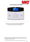
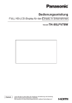
Montaggio su guida DIN
INSERIMENTO BATTERIE
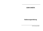
Prima di montare il remotizzatore sulla guida DIN inserire le batterie ricaricabili di backup nel seguente modo:
1. Svitare le quattro viti frontali del remotizzatore e premere sui dentini di tenuta superiori o inferiori per sganciare il coperchio.
2. Inserire 3 batterie ricaricabili NiMh - AAA rispettando le polarità indicate.
Si consiglia l’uso di batterie con capacità di 800 mAh o superiore.
1
3. Rimettere il coperchio al remotizzatore e fissarlo con le sue viti.
FISSAGGIO SU GUIDA DIN
Montare il remotizzatore sulla guida DIN da 35 mm nel seguente modo :
1. Inserire l’aggancio superiore del dispositivo nella guida DIN.
2. Ruotare il dispositivo finché non si sente un “clack” che segnala il bloccaggio sulla guida DIN.
1
2
9
I
T
A
L
I
A
N
O
INSTALLAZIONE
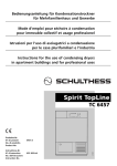
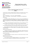
COLLEGAMENTO DELLE INTERFACCE
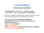
Prima di collegare le interfacce, togliere le etichette pretranciate che coprono i connettori necessari, come mostrato nell’immagine
che segue. Per sollevare l’etichetta ci si può aiutare con un cacciavite, facendo attenzione a non danneggiare il connettore sottostante.
Posizionare le interfacce a lato del remotizzatore, tenendo conto della lunghezza dei cavi di collegamento con connettori polarizzati
in dotazione.
10
INSTALLAZIONE
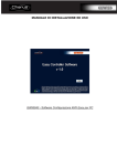
Connessioni elettriche
I
T
A
L
I
A
N
O
INGRESSI E USCITE LOCALI
RETE TELEFONICA
Remotizzatore GSM
ANTENNA
2
Sistema di rivelazione
presenza gas
(ad esempio alimentatore GW 10 719
+ rivelatore GW 10 711)
1
2
Note per l’installazione
1 I carichi collegati alle uscite non devono superare la capacità di commutazione dei relè del remotizzatore. Nel caso si
dovessero collegare carichi di elevata potenza si suggerisce di comandare con il remotizzatore un relè di potenza a cui
andranno collegati i carichi interessati.
2 Agli ingressi, se collegati, devono essere applicati segnali elettrici 12 V ac/dc ÷ 250 V ac.
La polarità va rispettata nel caso di collegamento di segnali in corrente continua.
11
INSTALLAZIONE
Connessioni seriali
CRONOTERMOSTATO DA INCASSO
RETE TELEFONICA
Remotizzatore GSM
ANTENNA
2
1
Cronotermostato
GW 10 703 - GW 12 703 - GW 14 703
Note per l’installazione
1 Per il collegamento seriale si possono usare conduttori in rame standard. Lunghezza max collegamento seriale: 20 m.
2 Caldaia o impianto di condizionamento.
12
INSTALLAZIONE
I
T
A
L
I
A
N
O
CRONOTERMOSTATO DA PARETE RF
RETE TELEFONICA
Remotizzatore GSM
ANTENNA
1
2
Cronotermostato RF
con linea seriale
GW 10 841 - GW 14 841
Attuatore RF 16A
per comando caldaia/condizionatore
(ad esempio GW 14 822)
Note per l’installazione
1 Per il collegamento seriale si possono usare conduttori in rame standard. Lunghezza max collegamento seriale: 20 m.
2 Caldaia o impianto di condizionamento
13
INSTALLAZIONE
Connessioni interfacce
INTERFACCIA DISPOSITIVI RF COMANDO E CONTROLLO
RETE TELEFONICA
Remotizzatore GSM
ANTENNA
Interfaccia RF
comando e controllo
GW 90 822
4
L N
RX GND TX
IN 1
IN 2 OUT 1 OUT 2
230 Vac
Telecomando RF
GW 20 963
230 Vac
Pulsantiera RF 3 canali
(ad esempio GW 14 803)
Cronotermostato RF
bidirezionale
Attuatore RF 16A
(ad esempio GW 14 822)
(ad esempio GW 14 851)
1
230 Vac
Note per l’installazione
1 Caldaia o impianto di condizionamento
Attuatore RF 16A
per comando caldaia/condizionatore
(ad esempio GW 14 822)
14
INSTALLAZIONE
I
T
A
L
I
A
N
O
INTERFACCIA SISTEMA ALLARME RF
RETE TELEFONICA
Remotizzatore GSM
ANTENNA
Interfaccia
remotizzatore
GSM - RF antifurto
(GW 90 823)
Rivelatore volumetrico
di presenza da parete
( ad esempio GW 14 861)
Rivelatore ottico
di fumo
Centrale di comando
(GW 20 483)
(ad esempio GW 20 470)
Telecomando
(GW 20 472)
Sirena da esterno
(GW 20 490)
15
INSTALLAZIONE
Inserimento SIM
Per inserire la SIM nell’apposito alloggiamento del remotizzatore:
1. Premere con la punta di una matita o di una biro il pulsantino giallo di sgancio posto accanto al cassettino porta SIM.
2. Aprire il cassettino porta SIM.
3. Inserire nel cassettino la SIM facendo attenzione che l’angolo smussato si trovi in alto a destra e i contatti dorati siano visibili
frontalmente.
4. Richiudere il cassettino porta SIM.
RF
RF
Sgancio cassettino SIM
Posizionamento connessione SIM
16
INSTALLAZIONE
Posizionamento e connessione antenna
Fare attenzione a posizionare l’antenna del remotizzatore:
• lontana da ogni eventuale fonte di disturbo elettromagnetico, come ad esempio contattori elettrici, motori elettrici, dimmer, lampade
fluorescenti;
• fuori da quadri elettrici o armadi metallici;
• non coperta da pannelli metallici o in loro vicinanza;
• in una zona asciutta (il contenitore dell’antenna non è stagno);
• in un posto protetto, per evitare che venga danneggiata accidentalmente o intenzionalmente.
L’antenna può essere fissata su una parete o supporto liscio mediante le strisce biadesive incluse nella confezione.
Per agevolare il posizionamento dell’antenna, il remotizzatore è fornito con una prolunga d’antenna di 1,5 m. Questa prolunga deve
essere usata solo se necessaria.
Collegare l’antenna avvitando il suo cavo al connettore SMA posto nella parte superiore del remotizzatore.
Avvitare a mano, senza l’uso di attrezzi, per evitare di danneggiare il connettore.
RF
RF
Messa in servizio
Dopo aver alimentato il dispositivo, il LED di segnalazione stato dispositivo inizia a lampeggiare indicando che è in corso la fase di
inizializzazione del modulo GSM.
Dopo circa 30 secondi il LED rimane acceso verde fisso: questo segnala che il dispositivo è stato inizializzato correttamente.
Se il LED di segnalazione stato del modulo GSM si accende verde significa che la rete GSM dell'operatore è disponibile; se si accende
rosso fisso significa che il segnale GSM non è sufficiente.
17
I
T
A
L
I
A
N
O
PROGRAMMAZIONE
Modalità di configurazione
Il remotizzatore può essere configurato con un PC, collegato al dispositivo mediante un cavo USB e munito del software di
configurazione, oppure con un telefono cellulare mediante l’invio di SMS.
La prima modalità è quella consigliata durante la prima installazione e configurazione, mentre la seconda risulta particolarmente utile
quando si deve modificare la configurazione del remotizzatore da remoto.
Per il corretto funzionamento del remotizzatore si devono configurare:
1. Password di accesso.
2. Numero telefonico di default per risposta
3. Numeri telefonici (opzionali) abilitati al comando dell’impianto antifurto o alla modifica dei parametri
4. Abilitazione interfacce presenti
5. Ingressi locali: evento di attivazione, testo del messaggio relativo all’evento, numero telefono destinatario SMS (solo se diverso da
quello di default).
6. Uscite locali: tipo di funzionamento (impulsivo, bistabile, temporizzato), durata della chiusura dei contatti (solo in caso di
funzionamento impulsivo o temporizzato), testo del messaggio di conferma.
7. Interfacce RF: condizioni invio SMS, testo del messaggio, numero telefono destinatario SMS (solo se diverso da quello di default).
Password
La password serve al remotizzatore per identificare il chiamante prima di eseguire le istruzioni ricevute via SMS. La password è
costituita da 4 caratteri alfanumerici, scelti a piacere dall’utente tra 0...9, a...z, A...Z.
Il remotizzatore riconosce la differenza tra lettere maiuscole e lettere minuscole, pertanto “ab12” è diverso da “AB12”.
Per la memorizzazione della password si veda il paragrafo Impostazioni di base.
Configurazione con PC
COLLEGAMENTO PC - REMOTIZZATORE
RF
RF
Nella fase di configurazione da PC il remotizzatore deve essere alimentato da rete.
USO DEL SOFTWARE DI CONFIGURAZIONE
Il software per la configurazione del dispositivo tramite PC è scaricabile dal sito Internet www.gewiss.com all'interno della pagina del
Remotizzatore GSM con I/O e linea seriale GW 90 821.
Il manuale d’uso del software è disponibile insieme al software stesso.
18
PROGRAMMAZIONE
Interazione e configurazione via SMS
Il remotizzatore accetta comandi ed interrogazioni via SMS verso il dispositivo o i sistemi ad esso collegati. I comandi sono sempre
ricevuti dal remotizzatore salvo inserimento della password, indipendentemente dal numero chiamante e dal fatto che esso sia visibile
o nascosto. Fanno eccezione i comandi di configurazione e quelli sull’impianto antifurto, che richiedono che il numero chiamante sia
visibile e appartenente all’elenco dei numeri di telefono memorizzati nella SIM nelle posizioni di memoria predefinite (si veda il
paragrafo Configurazione di base).
Queste le principali regole da seguire nella composizione degli SMS:
MAIUSCOLE E MINUSCOLE
Il remotizzatore riconosce la differenza tra lettere maiuscole e minuscole negli SMS (scrivere “p” non è come scrivere “P”). Le lettere
di tutti i comandi e impostazioni devono essere maiuscole.
STRUTTURA DELL’SMS INVIATO
Gli SMS iniziano con un punto (“.”) seguito dalla password (si veda il paragrafo Password), da un punto, dal comando e da un altro
punto. Non sono ammessi spazi tra i punti e la password o il comando.
Sintassi:
.password.comando.
Esempi di SMS corretti: .AB01.SGE00-0.
.AB01.P241-Pompa acqua ferma.
Esempi di SMS errati:
.AB01. SGE00-0.
.AB01 . SGE00-0.
COMANDI MULTIPLI
Con un singolo SMS si possono inviare più comandi separati tra loro da un punto (“.”). L’SMS non deve superare i 480 caratteri.
Sintassi: .password.comando1.comando2.comando3.comando4.
Esempio: .AB01.CAL01-1.CAR05-1.CCSS01-M-15,5.CAF00T.
TESTI PERSONALIZZATI
I testi personalizzati dei messaggi di risposta non possono superare i 24 caratteri, spazi compresi, e non devono contenere punti (“.”).
Sono consentiti gli altri caratteri di punteggiatura.
Esempio di testo corretto: Cronotermostato mare
Esempi di testo errati: Cronotermostato villa mare (testo troppo lungo), Cronoterm. villa mare (punto nel testo)
NUMERI DI TELEFONO
I numeri di telefono devono essere inseriti senza spazi o trattini di separazione. Occorre far precedere il numero dal prefisso
internazionale nella forma +prefisso (per l’Italia +39). Il telefono corrispondente al numero inserito deve essere in grado di ricevere
SMS.
I numeri memorizzati nel remotizzatore per l'invio di SMS devono essere nel formato internazionale corrispondente allo Stato in cui
il remotizzatore viene installato.
Il remotizzatore riconosce il numero del mittente dell'SMS solo se è nello stesso formato del numero memorizzato nella scheda SIM.
Esempi di numeri errati: +39 035 94611 (spazi), 338-55523 (trattino separatore e prefisso internazionale mancante)
Esempi di numeri corretti: +3903594611, +3933855523
Nell’inviare gli SMS di risposta il remotizzatore segue queste regole:
• Le risposte a comandi e interrogazioni di stato vengono inviate al numero chiamante, se è visibile, oppure al numero di default
(vedere Configurazione di base) se esso è nascosto.
• Gli SMS inviati in modo autonomo dal remotizzatore, ad esempio gli allarmi e la commutazione di ingressi, vengono inviati al
numero impostato per lo specifico evento o, in sua mancanza, al numero di default.
19
I
T
A
L
I
A
N
O
PROGRAMMAZIONE
Configurazione di base
Per motivi di sicurezza, alcune impostazioni non possono essere effettuate via SMS ma devono essere eseguite con un telefono
cellulare direttamente sulla SIM che verrà installata nel remotizzatore oppure programmate tramite il software.
Per impostare questi parametri da telefono cellulare fare quanto segue:
1. Inserire in un telefono cellulare la SIM che verrà usata, dopo averla eventualmente tolta dal remotizzatore. Fare riferimento al
manuale d’uso del telefono cellulare per i dettagli dell’operazione.
2. Memorizzare nella rubrica della SIM, usando tastiera e display del telefono cellulare, i parametri elencati nella seguente tabella
Nome contatto
Numero contatto
Posizione Descrizione
su SIM
su SIM (1)
memoria SIM
1
Password (4 caratteri alfanumerici)
Password
–
2
Numero di default per risposta
–
n. telefono
3
Numero 1 per controllo antifurto e modifica configurazione via SMS
–
n. telefono
4
Numero 2 per controllo antifurto e modifica configurazione via SMS
–
n. telefono
5
Numero 3 per controllo antifurto e modifica configurazione via SMS
–
n. telefono
6
Numero 4 per controllo antifurto e modifica configurazione via SMS
–
n. telefono
7
Numero 5 per controllo antifurto e modifica configurazione via SMS
–
n. telefono
(1) Per il formato di inserimento dei numeri di telefono nella scheda SIM si veda il paragrafo Numeri di telefono.
Su tutti i numeri impostati per il controllo dell'impianto antifurto verranno inviati i messaggi di segnalazione di allarme.
Per memorizzare i dati nella SIM fare quanto segue:
a) selezionare la posizione di memoria occorrente;
b) lasciare vuoto il “nome contatto”, tranne che nel caso della password in cui va inserita la password scelta;
c) inserire il numero di telefono nel “numero contatto” (la password non richiede nessun numero di telefono; eventuali numeri di
telefono vengono ignorati).
Prima di procedere alla memorizzazione dei numeri e della password nella SIM si consiglia di cancellare tutti i contatti presenti nella
scheda, per esser sicuri che i numeri inseriti vengano memorizzati nelle celle di memoria elencate.
Prima di modificare i numeri di telefono memorizzati nella SIM o la password è necessario togliere l'alimentazione al remotizzatore
per fare in modo che al riavvio i nuovi dati vengano trasferiti nella memoria interna del dispositivo.
È possibile omettere i numeri di telefono per il comando dell'antifurto (posizioni di memoria da 3 a 7) se non è presente l'interfaccia
remotizzatore GSM RF antifurto (GW 90 823). In questo caso la configurazione dei parametri da SMS può essere fatta solo dal numero
di telefono di default.
3. Togliere la SIM dal telefono cellulare e inserirla nel remotizzatore come illustrato nel paragrafo Inserimento SIM.
ATTENZIONE: Se la configurazione viene eseguita da software i dati vengono automaticamente memorizzati nelle posizioni
elencate in tabella, sovrascrivendo eventuali informazioni presenti nella SIM.
Configurazioni via SMS
I parametri che seguono devono essere configurati via SMS. L’SMS è accettato solo se proviene da un numero chiamante in chiaro
che corrisponde ad uno dei numeri memorizzati nella SIM (numero di default e numeri abilitati alla configurazione dei parametri).
Il valore sottolineato indica il valore di default.
CONFIGURAZIONE GENERALE
Comando
P200-1
P200-0
P201-1
P201-0
P202-1
P202-0
P203-1
P203-0
Descrizione
Invia copia dei messaggi anche sul numero di telefono di default
Non invia copia dei messaggi anche sul numero di telefono di default
Non usato
Non usato
Interfaccia RF presente
Interfaccia RF non presente
Interfaccia RF Antifurto presente
Interfaccia RF Antifurto non presente
20
PROGRAMMAZIONE
CONFIGURAZIONE INGRESSI LOCALI
Comando
P240-0
P240-1
P240-2
P240-3
P241-testo
P242-testo
P243-telefono
P250-0
P250-1
P250-2
P250-3
P251-testo
P252-testo
P253-telefono
Descrizione
INP1: condizione invio SMS: ricezione “OFF”
INP1: condizione invio SMS: ricezione “ON”
INP1: condizione invio SMS: ricezione “ON” e “OFF”
INP1: invio SMS solo su richiesta
INP1: testo del messaggio SMS per ricezione “ON”
INP1: testo del messaggio SMS per ricezione “OFF”
Numero di telefono a cui vengono inviati gli SMS dell’ingresso locale 1
INP2: condizione invio SMS: ricezione “OFF”
INP2: condizione invio SMS: ricezione “ON”
INP2: condizione invio SMS: ricezione “ON” e “OFF”
INP1: invio SMS solo su richiesta
INP2: testo del messaggio SMS per ricezione “ON”
INP2: testo del messaggio SMS per ricezione “OFF”
Numero di telefono a cui vengono inviati gli SMS dell’ingresso locale 2
CONFIGURAZIONE USCITE LOCALI
Comando
P280-0
P280-1
P280-2
P281-0
P281-1
P281-2
P281-3
P281-4
P281-5
P281-6
P282-testo
P290-0
P290-1
P290-2
P291-0
P291-1
P291-2
P291-3
P291-4
P291-5
P291-6
P292-testo
Descrizione
OUT1: modalità commutazione bistabile
OUT1: modalità commutazione impulsiva
OUT1: modalità commutazione temporizzata
OUT1: durata 1 [bistabile: NA; impulsiva = 300ms; temporizzata = 30sec]
OUT1: durata 2 [bistabile: NA; impulsiva = 500ms; temporizzata = 60sec]
OUT1: durata 3 [bistabile: NA; impulsiva = 800ms; temporizzata = 5 min]
OUT1: durata 4 [bistabile: NA; impulsiva = 1 sec; temporizzata = 10 min]
OUT1: durata 5 [bistabile: NA; impulsiva = 2 sec; temporizzata = 30 min]
OUT1: durata 6 [bistabile: NA; impulsiva = 5 sec; temporizzata = 1 h]
OUT1: durata 7 [bistabile: NA; impulsiva = 10 sec; temporizzata = 2 h]
OUT1: testo del messaggio SMS di conferma
OUT2: modalità commutazione bistabile
OUT2: modalità commutazione impulsiva
OUT2: modalità commutazione temporizzata
OUT2: durata 1 [bistabile: NA; impulsiva = 300ms; temporizzata = 30sec]
OUT2: durata 2 [bistabile: NA; impulsiva = 500ms; temporizzata = 60sec]
OUT2: durata 3 [bistabile:NA; impulsiva = 800ms; temporizzata = 5 min]
OUT2: durata 4 [bistabile:NA; impulsiva = 1 sec; temporizzata = 10 min]
OUT2: durata 5 [bistabile:NA; impulsiva = 2 sec; temporizzata = 30 min]
OUT2: durata 6 [bistabile:NA; impulsiva = 5 sec; temporizzata = 1 h]
OUT2: durata 7 [bistabile:NA; impulsiva = 10 sec; temporizzata = 2 h]
OUT2: testo del messaggio SMS di conferma
CONFIGURAZIONE CRONOTERMOSTATO/PROGRAMMATORE ELETTRONICO
Comando
P710-0
P710-1
P710-2
P711-testo
Descrizione
Nessun dispositivo seriale collegato
Dispositivo seriale collegato = cronotermostato (GW 1X 701, GW 1X 703, GW 1X 841)
Dispositivo seriale collegato = programmatore elettronico (GW 1X 581)
Denominazione del dispositivo seriale collegato
21
I
T
A
L
I
A
N
O
PROGRAMMAZIONE
CONFIGURAZIONE INGRESSI RF
Comando
P300-0
P300-1
P300-2
P300-3
P301-testo
P302-testo
P303-telefono
P310-0
P310-1
P310-2
P310-3
P311-testo
P312-testo
P313-numero telefonico
Descrizione
INP_RF1: condizione invio SMS: ricezione “ON”
INP_RF1: condizione invio SMS: ricezione “OFF”
INP_RF1: condizione invio SMS: ricezione “ON” e “OFF”
INP_RF1: invio SMS solo su richiesta
INP_RF1: testo del messaggio SMS per ricezione “ON”
INP_RF1: testo del messaggio SMS per ricezione “OFF”
Numero di telefono a cui vengono inviati gli SMS dell’ingresso RF 1
INP_RF2: condizione invio SMS: ricezione “ON”
INP_RF2: condizione invio SMS: ricezione “OFF”
INP_RF2: condizione invio SMS: ricezione “ON” e “OFF”
INP_RF2: invio SMS solo su richiesta
INP_RF2: testo del messaggio SMS per ricezione “ON”
INP_RF2: testo del messaggio SMS per ricezione “OFF”
Numero di telefono a cui vengono inviati gli SMS dell’ingresso RF 2
CONFIGURAZIONE USCITE RF
Comando
P320-testo
P330-testo
P340-testo
P350-testo
P360-testo
P720-0
P720-1
P721-testo
Descrizione
OUT_RF1: testo del messaggio SMS di conferma
OUT_RF2: testo del messaggio SMS di conferma
OUT_RF3: testo del messaggio SMS di conferma
OUT_RF4: testo del messaggio SMS di conferma
OUT_RF5: testo del messaggio SMS di conferma
Dispositivo cronotermostato RF bidirezionale non collegato
Dispositivo cronotermostato RF bidirezionale collegato
Denominazione del cronotermostato RF bidirezionale utilizzato
CONFIGURAZIONE IMPIANTI ANTIFURTO
Comando
P760-testo
P761-testo
P762-testo
P763-testo
P764-testo
P765-testo
P766-testo
P767-testo
P768-testo
P769-testo
P770-testo
Evento
Testo del messaggio SMS in caso di evento manomissione
Testo del messaggio SMS in caso di allarme antifurto
Testo del messaggio SMS in caso di evento anomalia
Testo del messaggio SMS in caso di allarme panico
Testo del messaggio SMS in caso di memoria allarme antifurto
Testo del messaggio SMS in caso di memoria manomissione
Testo del messaggio SMS in caso di memoria anomalia
Centrale inserita
Centrale disinserita
Centrale pronta
Centrale non pronta
22
PROGRAMMAZIONE
RICHIESTA CONFIGURAZIONE
Comando
R200
R220
R240
R280
R300
R320
R700
R750
Descrizione
Invia SMS con le impostazioni generali
Non usato
Invia SMS con le impostazioni degli ingressi locali
Invia SMS con le impostazioni delle uscite locali
Invia SMS con le impostazioni degli ingressi RF
Invia SMS con le impostazioni delle uscite RF
Invia SMS con le impostazioni della termoregolazione
Invia SMS con le impostazioni dell’impianto antifurto
Collaudo
Al termine dell’installazione e configurazione del remotizzatore provare le principali funzioni implementate per verificarne il
corretto funzionamento.
23
I
T
A
L
I
A
N
O
IN SERVIZIO
Gestione da remoto via SMS
I comandi per interagire da remoto, via SMS, con i vari ingressi, uscite e sistemi connessi sono elencati nelle tabelle che seguono.
COMANDI USCITE LOCALI
Comando
CAL01-1
CAL01-0
CAL02-1
CAL02-0
Descrizione
Attiva relè uscita 1
Disattiva relè uscita 1 (e termine eventuale temporizzazione in corso)
Attiva relè uscita 2
Disattiva relè uscita 2 (e termine eventuale temporizzazione in corso)
COMANDI USCITE SOTTOSISTEMA RF
Comando
CAR01-1
CAR01-0
CAR02-1
CAR02-0
CAR03-1
CAR03-0
CAR04-1
CAR04-0
CAR05-1
CAR05-0
Descrizione
Attiva relè uscita RF 1
Disattiva relè uscita RF 1 (se relè configurato come bistabile e termine eventuale disattivazione)
Attiva relè uscita RF 2
OUT_RF2: Disattivazione relè (solo se attuatore configurato come bistabile e termine eventuale disattivazione)
Attiva relè uscita RF 3
OUT_RF3: Disattivazione relè (solo se attuatore configurato come bistabile e termine eventuale disattivazione)
Attiva relè uscita RF 4
OUT_RF4: Disattivazione relè (solo se attuatore configurato come bistabile e termine eventuale disattivazione)
Attiva relè uscita RF 5
OUT_RF5: Disattivazione relè (solo se attuatore configurato come bistabile e termine eventuale disattivazione)
COMANDI PER PROGRAMMATORE ELETTRONICO (SERIALE)
Comando
COP01-A
COP01-O (1)
COP01-1
COP01-0
Descrizione
Attiva modalità AUTO
Attiva modalità OFF
Attiva modalità MAN con uscita ON
Attiva modalità MAN con uscita OFF
(1) L'ultimo carattere è una “O” maiuscola.
COMANDI PER CRONOTERMOSTATI CON SERIALE
Comando
CCS01-H
CCS01-C
CCS01-O (1)
CCS01-A
CCS01-1
CCS01-2
CCS01-3
CCS01-M-temperatura
Descrizione
Imposta il tipo di funzionamento RISCALDAMENTO
Imposta il tipo di funzionamento CONDIZIONAMENTO
Imposta la modalità OFF
Imposta la modalità AUTO
Imposta la modalità MANUALE con temperatura T1
Imposta la modalità MANUALE con temperatura T2
Imposta la modalità MANUALE con temperatura T3
Imposta la modalità MANUALE, specificando la temperatura da mantenere, con risoluzione di 0,5° e virgola separatrice. Es. 18,0 oppure 21,5.
(1) L'ultimo carattere è una “O” maiuscola.
24
IN SERVIZIO
COMANDI PER CRONOTERMOSTATO RF BIDIREZIONALE
Comando
CCR01-H
CCR01-C
CCR01-O (1)
CCR01-A
CCR01-1
CCR01-2
CCR01-3
CCR01-M-temperatura
Descrizione
Imposta il tipo di funzionamento RISCALDAMENTO
Imposta il tipo di funzionamento CONDIZIONAMENTO
Imposta la modalità OFF
Imposta la modalità AUTO
Imposta la modalità MANUALE con temperatura T1
Imposta la modalità MANUALE con temperatura T2
Imposta la modalità MANUALE con temperatura T3
Imposta la modalità MANUALE, specificando la temperatura da mantenere, con risoluzione di 0,5°
e virgola separatrice. Es. 18,0 oppure 21,5.
(1) L'ultimo carattere è una “O” maiuscola.
COMANDI PER ANTIFURTO RF
Comando
CAF00-T
CAF00-0
CAF00-1
CAF00-2
CAF00-A
CAF00-D
Descrizione
Attiva l’antifurto (tutte le zone)
Disattiva l’antifurto
Attiva l’antifurto per la zona 1
Attiva l’antifurto per la zona 2
Abilita la notifica di inserimento/disinserimento della centrale antifurto
Disabilita la notifica di inserimento/disinserimento della centrale antifurto
COMANDI DI RICHIESTA STATO
Comando
SGE00-0
SGE00-1
SGE00-2
SGE00-3
Descrizione
Richiesta di stato per tutti gli I/O e i dispositivi gestiti
Richiesta di stato per gli I/O locali e il sottosistema RF
Richiesta di stato per i cronotermostati e il programmatore elettronico
Richiesta di stato per l’impianto antifurto
Indicazioni locali
Sul remotizzatore, frontalmente, sono posti 2 LED per segnalare lo stato di funzionamento del dispositivo.
LED di segnalazione stato dispositivo
LED acceso fisso
nessuna anomalia
LED di segnalazione stato modulo GSM
LED acceso (verde)
rete GSM presente
LED lampeggiante
LED acceso (rosso)
rete GSM assente
LED acceso (giallo)
elaborazione di un SMS ricevuto
• configurazione dispositivo in
corso
• anomalia (SIM non pronta, SIM
protetta da codice PIN...)
25
I
T
A
L
I
A
N
O
IN SERVIZIO
Comandi locali
Premendo il pulsante posto frontalmente sul remotizzatore si commuta lo stato dei contatti di entrambi i relè locali nel seguente
modo:
Prima
relè 1
OFF
ON
OFF
ON
Dopo
relè 2
OFF
OFF
ON
ON
relè 1
ON
OFF
OFF
OFF
relè 2
ON
OFF
OFF
OFF
Funzionamento in caso di blackout
In caso di blackout il remotizzatore invia un SMS per segnalare la mancanza di tensione di rete e ne invia un altro quando ritorna per
segnalarne il ripristino. Durante il blackout il remotizzatore continua ad essere alimentato dalle batterie di backup: non è in grado di
ricevere SMS ma può inviare gli SMS di segnalazione che provengono dall’impianto antifurto (se è presente l’interfaccia GSM RF
antifurto).
Il numero di SMS che il remotizzatore può inviare quando è alimentato dalle batterie di backup dipende dalla capacità delle batterie
inserite, dal loro stato di carica iniziale, dal tempo trascorso dall’inizio del blackout e dal numero di messaggi già inviati. A solo titolo
di esempio il remotizzatore, con le batterie consigliate (800 mAh) a piena carica, ha un’autonomia di 7 giorni o 7 SMS (6 d’allarme
più 1 di segnalazione di mancanza di tensione di rete).
Pulizia del remotizzatore
Per un’eventuale pulizia adoperare un panno asciutto.
Sostituzione batterie
Le batterie di backup non necessitano di sostituzione. Nel caso dovessero essere sostituite fare riferimento al paragrafo Inserimento
batterie. Le nuove batterie ricaricabili devono essere di tipo NiMh, formato AAA.
ATTENZIONE
- La sostituzione delle batterie deve essere fatta esclusivamente dall’installatore dopo aver tolto la tensione di rete.
L'interruzione dell'alimentazione di rete cancella anche la segnalazione "SOSTITUIRE BATTERIE".
- Sostituire tutte 3 le batterie contemporaneamente.
- Non utilizzare insieme batterie vecchie e nuove.
- Utilizzare batterie dello stesso tipo (non mischiare batterie con capacità diverse).
- Non gettare le batterie nel fuoco.
- Le batterie sono rifiuti speciali, il cui smaltimento è regolamentato da precise predisposizione di legge, e devono essere
conferite agli appositi centri di raccolta.
Ricarica SIM
Nel caso si utilizzi una SIM prepagata occorre garantire che ci sia sempre un credito sufficiente per l’invio dei messaggi di allarme e
di riscontro da parte del remotizzatore.
Per le procedure di ricarica, di controllo del credito residuo e per l’eventuale attivazione del servizio di autoricarica fare riferimento
alle procedure adottate dal gestore di telefonia mobile prescelto.
26
DATI TECNICI
Comunicazione remota
Elementi di comunicazione
Alimentazione
Attraverso rete GSM
1 modulo GSM quadband
230 V ac + 3 batterie ricaricabili NiMh AAA di backup
(capacità consigliata 800 mAh o superiore)
2W
1 pulsante di commutazione stato uscite
1 LED multifunzione rosso/verde/giallo per segnalazione stato
modulo GSM
1 LED rosso per segnalazione stato dispositivo
2 relè 10 A con contatto NA libero da potenziale
Durata chiusura configurabile da 300 ms a 2 h
2 NA da 10 A (AC1) / 4 A (AC15) - 250 Vac
2 da 12V ac/dc ÷ 250 V ac
Durata minima impulso 500 ms
Interno, luoghi asciutti
-5 ÷ +45 °C
-25 ÷ +70 °C
Max 93% (non condensante)
1 porta USB di tipo B
1 connettore 4 vie
1 connettore 6 vie
Morsetti a vite, sezione max cavi: 2,5 mm2
Lunghezza max: 20 m
Morsetti a vite, sezione max cavi: 2,5 mm2
IP20
6 moduli DIN
Direttiva bassa tensione 72/23/CE
Direttiva compatibilità elettromagnetica 89/336/CEE
ETSI EN301 489-7, ETSI EN301 511
Potenza assorbita
Elementi di comando
Elementi di visualizzazione
Elementi di attuazione
Contatto di uscita
Ingressi
Ambiente di utilizzo
Temperatura di funzionamento
Temperatura di stoccaggio
Umidità relativa
Connessione PC
Connessione interfaccia RF comando e controllo
Connessione interfaccia RF antifurto
Connessione seriale
Connessioni elettriche
Grado di protezione
Dimensione
Riferimenti normativi
Valori preimpostati
Abilitazione funzione messaggio copia
0 = nessun dispositivo collegato
OPZIONI BASE
Abilitazione interfaccia RF comando e controllo GW 90 822
Abilitazione interfaccia RF antifurto GW 90823
Testo conferma commutazione uscite
Testo di notifica mancanza alimentazione
Testo di notifica ripristino alimentazione
Testo di richiesta sostituzione batterie
0 = no
0 = no
ESEGUITO
ASSENZA RETE 230 V
RETE 230 V OK
SOSTITUIRE BATTERIE
SIM
Password (4 caratteri alfanumerici)
0000
27
I
T
A
L
I
A
N
O
DATI TECNICI
I/O LOCALI
Condizione di invio SMS per l’ingresso 1
Testo del messaggio SMS per ricezione “ON”
Testo del messaggio SMS per ricezione “OFF”
Condizione di invio SMS per l’ingresso 2
Testo del messaggio SMS per ricezione “ON”
Testo del messaggio SMS per ricezione “OFF”
Modalità commutazione relè 1
Testo del messaggio SMS di conferma
Modalità commutazione relè 2
Testo del messaggio SMS di conferma
1 = invio su ricezione ON
INGRESSO 1=ON
INGRESSO 1=OFF
1 = invio su ricezione ON
INGRESSO 2=ON
INGRESSO 2=OFF
0 = Commutazione bistabile
OUT1
0 = Commutazione bistabile
OUT2
TERMOREGOLAZIONI
Dispositivo seriale collegato
Denominazione del dispositivo seriale collegato
0 = nessun dispositivo collegato
CRONOTERMOSTATO
RF COMANDO E CONTROLLO
Condizione di invio SMS per l’ingresso 1
Testo del messaggio SMS per ricezione “ON”
Testo del messaggio SMS per ricezione “OFF”
Condizione di invio SMS per l’ingresso 2
Testo del messaggio SMS per ricezione “ON”
Testo del messaggio SMS per ricezione “OFF”
Uscita 1: Testo del messaggio SMS di conferma
Uscita 2: Testo del messaggio SMS di conferma
Uscita 3: Testo del messaggio SMS di conferma
Uscita 4: Testo del messaggio SMS di conferma
Uscita 5: Testo del messaggio SMS di conferma
Dispositivo cronotermostato RF bidirezionale collegato
Denominazione del cronotermostato RF bidirezionale collegato
1 = invio su ricezione ON
INGRESSO RF1=ON
INGRESSO RF1=OFF
1 = invio su ricezione ON
INGRESSO RF2=ON
INGRESSO RF2=OFF
OUT_RF1
OUT_RF2
OUT_RF3
OUT_RF4
OUT_RF5
0 = no
CRONOTERMOSTATO
ANTIFURTO
Messaggio evento manomissione
Messaggio evento allarme
Messaggio evento anomalia
Messaggio di allarme panico
Messaggio di memoria allarme
Messaggio di memoria manomissione
Messaggio di memoria anomalia
Messaggio per “centrale inserita”
Messaggio per “centrale non inserita”
Messaggio per “centrale pronta all’inserimento”
Messaggio per “centrale non pronta all’inserimento”
MANOMISSIONE
ALLARME ANTIFURTO
ANOMALIA ANTIFURTO
ALLARME PANICO
MEMORIA ALLARME
MEMORIA MANOMISSIONE
MEMORIA ANOMALIA
CENTRALE INSERITA
CENTRALE DISINSERITA
CENTRALE PRONTA
CENTRALE NON PRONTA
28
CONTENTS
GENERAL WARNINGS
Contents of the pack . . . . . . . . . . . . . . . . . . . . . . . . . . . . . . . . . . . . . . . . . . . . . . . . . . . . . . . . . . . . . . . . . . . . . . . . . . . . . . . .30
GENERAL DESCRIPTION
Summary . . . . . . . . . . . . . . . . . . . . . . . . . . . . . . . . . . . . . . . . . . . . . . . . . . . . . . . . . . . . . . . . . . . . . . . . . . . . . . . . . . . . . . . .31
Functions . . . . . . . . . . . . . . . . . . . . . . . . . . . . . . . . . . . . . . . . . . . . . . . . . . . . . . . . . . . . . . . . . . . . . . . . . . . . . . . . . . . . . . . .32
INSTALLATION
Warnings for installation phase . . . . . . . . . . . . . . . . . . . . . . . . . . . . . . . . . . . . . . . . . . . . . . . . . . . . . . . . . . . . . . . . . . . . . . . .34
Verification of GSM signal cover . . . . . . . . . . . . . . . . . . . . . . . . . . . . . . . . . . . . . . . . . . . . . . . . . . . . . . . . . . . . . . . . . . . . . . .34
SIM . . . . . . . . . . . . . . . . . . . . . . . . . . . . . . . . . . . . . . . . . . . . . . . . . . . . . . . . . . . . . . . . . . . . . . . . . . . . . . . . . . . . . . . . . . . . .34
Assembly on the DIN Rail . . . . . . . . . . . . . . . . . . . . . . . . . . . . . . . . . . . . . . . . . . . . . . . . . . . . . . . . . . . . . . . . . . . . . . . . . . . .35
Electrical connections . . . . . . . . . . . . . . . . . . . . . . . . . . . . . . . . . . . . . . . . . . . . . . . . . . . . . . . . . . . . . . . . . . . . . . . . . . . . . . .37
Serial connections . . . . . . . . . . . . . . . . . . . . . . . . . . . . . . . . . . . . . . . . . . . . . . . . . . . . . . . . . . . . . . . . . . . . . . . . . . . . . . . . .38
Interface connections . . . . . . . . . . . . . . . . . . . . . . . . . . . . . . . . . . . . . . . . . . . . . . . . . . . . . . . . . . . . . . . . . . . . . . . . . . . . . . .40
SIM insertion . . . . . . . . . . . . . . . . . . . . . . . . . . . . . . . . . . . . . . . . . . . . . . . . . . . . . . . . . . . . . . . . . . . . . . . . . . . . . . . . . . . . .42
Aerial position and connection . . . . . . . . . . . . . . . . . . . . . . . . . . . . . . . . . . . . . . . . . . . . . . . . . . . . . . . . . . . . . . . . . . . . . . . .43
Commissioning . . . . . . . . . . . . . . . . . . . . . . . . . . . . . . . . . . . . . . . . . . . . . . . . . . . . . . . . . . . . . . . . . . . . . . . . . . . . . . . . . . . .43
PROGRAMMING
Configuration Procedures . . . . . . . . . . . . . . . . . . . . . . . . . . . . . . . . . . . . . . . . . . . . . . . . . . . . . . . . . . . . . . . . . . . . . . . . . . . .44
Password . . . . . . . . . . . . . . . . . . . . . . . . . . . . . . . . . . . . . . . . . . . . . . . . . . . . . . . . . . . . . . . . . . . . . . . . . . . . . . . . . . . . . . . .44
PC configuration . . . . . . . . . . . . . . . . . . . . . . . . . . . . . . . . . . . . . . . . . . . . . . . . . . . . . . . . . . . . . . . . . . . . . . . . . . . . . . . . . . .44
Interaction and configuration via SMS . . . . . . . . . . . . . . . . . . . . . . . . . . . . . . . . . . . . . . . . . . . . . . . . . . . . . . . . . . . . . . . . . . .45
Basic configuration . . . . . . . . . . . . . . . . . . . . . . . . . . . . . . . . . . . . . . . . . . . . . . . . . . . . . . . . . . . . . . . . . . . . . . . . . . . . . . . . .46
Configuration via SMS . . . . . . . . . . . . . . . . . . . . . . . . . . . . . . . . . . . . . . . . . . . . . . . . . . . . . . . . . . . . . . . . . . . . . . . . . . . . . . .46
Final Inspection . . . . . . . . . . . . . . . . . . . . . . . . . . . . . . . . . . . . . . . . . . . . . . . . . . . . . . . . . . . . . . . . . . . . . . . . . . . . . . . . . . .49
IN SERVICE
Remote control via SMS . . . . . . . . . . . . . . . . . . . . . . . . . . . . . . . . . . . . . . . . . . . . . . . . . . . . . . . . . . . . . . . . . . . . . . . . . . . . .50
Local indications . . . . . . . . . . . . . . . . . . . . . . . . . . . . . . . . . . . . . . . . . . . . . . . . . . . . . . . . . . . . . . . . . . . . . . . . . . . . . . . . . . .51
Local commands . . . . . . . . . . . . . . . . . . . . . . . . . . . . . . . . . . . . . . . . . . . . . . . . . . . . . . . . . . . . . . . . . . . . . . . . . . . . . . . . . .52
Emergency Blackout Function . . . . . . . . . . . . . . . . . . . . . . . . . . . . . . . . . . . . . . . . . . . . . . . . . . . . . . . . . . . . . . . . . . . . . . . . .52
Cleaning the repeater . . . . . . . . . . . . . . . . . . . . . . . . . . . . . . . . . . . . . . . . . . . . . . . . . . . . . . . . . . . . . . . . . . . . . . . . . . . . . . .52
Replacing the batteries . . . . . . . . . . . . . . . . . . . . . . . . . . . . . . . . . . . . . . . . . . . . . . . . . . . . . . . . . . . . . . . . . . . . . . . . . . . . .52
Recharging the SIM . . . . . . . . . . . . . . . . . . . . . . . . . . . . . . . . . . . . . . . . . . . . . . . . . . . . . . . . . . . . . . . . . . . . . . . . . . . . . . . .52
Default values . . . . . . . . . . . . . . . . . . . . . . . . . . . . . . . . . . . . . . . . . . . . . . . . . . . . . . . . . . . . . . . . . . . . . . . . . . . . . . . . . . . . .53
TECHNICAL DATA . . . . . . . . . . . . . . . . . . . . . . . . . . . . . . . . . . . . . . . . . . . . . . . . . . . . . . . . . . . . . . . . . . . . . . . .54
Default values . . . . . . . . . . . . . . . . . . . . . . . . . . . . . . . . . . . . . . . . . . . . . . . . . . . . . . . . . . . . . . . . . . . . . . . . . . . . . . . . . . . . .54
29
E
N
G
L
I
S
H
GENERAL WARNINGS
Warning! The safety levels of this device can only be guaranteed if these instructions are fully observed. It is therefore essential to
carefully read and keep them for future reference. All Chorus products must be installed in compliance to CEI 64-8 Standards for
household appliances and similar items, in dust-free environments where no special protection is required to prevent penetration of
water.
The GEWISS sales division is at your complete disposal for any further technical details or information you may require.
Gewiss SpA reserves the right to make any modifications to the products described in this manual at any time without prior
warning.
Contents of the pack
n. 1 GSM repeater with I/O and serial line - DIN Rail
n. 1 Aerial
n. 1 Aerial extension cable 1.5 m
n. 2 Double-sided adhesive
n. 1 Installation and user manual
30
GENERAL DESCRIPTION
Summary
The GSM repeater with I/O and serial line - DIN Rail allows you to remotely control electrical charges through two relays without
potential contacts using SMS messages sent from a cell phone, and to receive status and alarm signals from two digital inputs directly
on your cell phone. The relay commands can be bistable, timed or impulse; the inputs are able to detect a status or an edge change.
The serial line connection fitted on the repeater allows you to handle an electronic programming unit (for instance a GW 14 581 ) or
a timer-thermostat (for instance GW 14 701, GW 10 703, GW 14 841 ).
It is therefore possible to remotely control, for instance the enabling/disabling programme on the electronic programming unit, or set
the function modes for the thermal regulation system and request the function parameters and the room temperature.
Using the relative interface it is also possible to interact remotely with the following Gewiss systems:
• RF burglar alarm system, for total or partial arming of the system, disabling or status request, and to receive automatic burglar alarm
activation, tampering, malfunction and panic signals;
• RF control and command, enabling or disabling of charges connected to RF actuator modules, receiving of signals from transmitters
such as push-button panels, sensors and remote controls, or control and request status of a bidirectional RF timer-thermostat;
The repeater is fitted with a rechargeable back-up battery to power it when the network power is down: it is therefore possible to detect
a blackout and the RF burglar alarm system can send alarm, malfunction or tamper signals. The repeater is customised using a PC
connected to the device through a USB port, using the configuration software, or by sending codes by SMS.
The repeater is fitted on a 35 mm DIN Rail, inside electric panels or junction boxes.
13
1
2
12
3
4
5
6
7
11
8
10
9
14
8
7
9
10
11
12
13
14
1
2
3
4
5
6
31
230 V ac power
Serial line:
Input 1
Input 2
Output relay 1
Output relay 2
Device status indicator LED
Multi-function GSM module status indicator
LED
GSM repeater – RF burglar alarm system connection interface
Output relay switching button
USB Port (type B)
External aerial connection
SIM card slot
GSM repeater – RF burglar alarm system
command and control connection interface
E
N
G
L
I
S
H
GENERAL DESCRIPTION
Functions
MANAGEABLE FUNCTIONS
Output relay timer switching
Output relay impulse switching
■
■
■
■
■
Motor command (e.g. shutters)
■
■
■
■
Sending of SMS on receiving "ON"
Sending of SMS on receiving "OFF"
Sending of SMS on receiving "ON" and “OFF”
Sending of SMS only on request
Setting of timer-thermostat function type
(heating/air conditioning);
■
■ (3)
Setting of thermal regulation system function mode
(auto/manual/OFF);
■
■ (3)
Manual setting of the set point
■
■
■ (3)
■ (3)
Request for timer-thermostat status
With RF burglar
alarm and interface
(GW 90 823)
■
■ (5)
■ (1) (2)
■
■
Output relay switching
With RF devices
and interface
(GW 90 822)
With electronic
programmer and
serial connection
With
timer-thermostat
and serial connection
With internal
inputs and outputs
The chart below lists the functions that can be managed by the repeater, directly or through other Gewiss devices.
■
■
■
■
Activation of manual mode with output ON
Activation of manual mode with output OFF
Activation of AUTO mode
Request for electronic programmer status
■
■
■
■
■
■ (4)
Total arming of the alarm system
Partial arming of the alarm system (zone 1)
Partial arming of the alarm system (zone 2)
Complete disarming of the burglar alarm system
Request for burglar alarm status
Alarm signal
(1) The output relays are bistable, therefore when the blackout ends they maintain the previously set status. If the output relays are
configured as timers they will open at the end of a blackout.
(2) It is possible to open the local relay contacts by pressing the front button on the repeater.
(3) With the wall bidirectional RF timer-thermostat (GW 10 851 - GW 14 851).
(4) Signal sent automatically if the burglar alarm goes off, if there is tampering, a malfunction or panic alarm signal.
(5) The timing intervals are counted by the RF actuator and not by the repeater. At the end of the blackout the relay will return to the
OFF status.
32
GENERAL DESCRIPTION
MESSAGES SENT BY THE REPEATER
▲
▲
▲
▲
▲
▲
■
■
Customised
Text
Send to default
number
■
■
■
■
■
■
Default Text
Send to calling
number
The repeater sends - following a direct request, in response to an order received or the indication of an event in progress - the
messages below:
Confirmation of execution of a command after sending a request
Internal relay switching
RF device relay switching
Motor command
Setting of timer-thermostat function type
Setting of timer-thermostat function mode
Setting of electronic programmer function mode
Arming/disarming of the burglar alarm system
Activation/deactivation signal of arming/disarming
■
■
■
■
■
■
■
■
Status signals sent automatically
■
■
■
Variation in local input status
Variation in RF device input status
Burglar system alarm indicator
■
■
■
Status indicator in response to a request
■
■
■
■
Status request for all managed devices
Status request for the local I/0 and SF subsystems
Status request for timer-thermostats (1)
Status request for electronic programmer (2)
Status request for burglar alarm system (3)
▲
▲
▲
▲
■
■
■
■
■
■
▲ The reply is sent to the default telephone number if the calling number is hidden.
(1) The reply includes the current function type and mode, the currently set temperature set point, the room temperature and the
actuator status (ON/OFF), except for the RF timer-thermostats where the sent command is notified as the actuator does not
respond to the command.
(2) The reply includes the function mode and contact status.
(3) The reply includes the system status (armed/disarmed) the unit status (ready/not ready for arming), alarm memory, tamper
memory, malfunction memory and the burglar alarm system arming/disarming notice status.
The SMS that confirm that a command has been executed and indicate the status of devices, and are sent by the repeater after
receiving a request, are sent to the calling number, none excluded (upon entering the password).
The only exception is the burglar alarm status, which must be sent by a telephone number memorised in the SIM as the default
number for controlling the burglar alarm system.
The status indicator SMS sent autonomously by the repeater are sent to the numbers indicated during the setup procedure or, if not
specified, to the default telephone number. The only exceptions are the burglar alarm signals, which are sent to the telephone numbers
memorised in the SIM as the default number for controlling the burglar alarm system.
33
E
N
G
L
I
S
H
INSTALLATION
WARNING: only qualified personnel are permitted to install this device, according to the regulations in force.
Warnings for installation phase
The repeater uses radiofrequency connections for remote and GSM wireless connections and to interact with the RF burglar alarm
system and the RF command and control system through the relative RF interfaces.
It is therefore essential to adopt a series of precautions:
• position the repeater aerial and any RF interfaces as far as possible from all sources of electromagnetic disturbances, such as
electrical motors, electricity meters, dimmers, fluorescent lights;
• NEVER install the repeater aerial and any RF interfaces inside control panels or metal cabinets;
• NEVER install the repeater aerial and any RF interfaces in front or behind metal panels;
• make sure that any RF interfaces are able to dialogue with the foreseen devices, before installation is completed; perform some
preliminary wireless connection tests (please refer to the technical manuals for each interface for further instructions).
It is recommended to install a short-circuit protection device upstream of the repeater (for instance a magnetothermal switch) which
can be useful for sectioning the line during maintenance or modifications to the repeater connections.
Verification of GSM signal cover
The repeater works with all GSM mobile phone providers. It is necessary however that the GSM network provider covers the selected
installation zone and that the GSM signal is sufficiently strong. To check the signal, use a cell phone with a SIM card connected to the
provider from the exact position you intend to install the units. If the signal is weak or not available, proceed as follows:
1. Try another position, until you find an acceptable signal level.
2. Try repositioning the aerial or replacing it with a compatible type (see the Positioning and connecting the aerial paragraph).
3. Try using a SIM card connected to a different provider (the GSM cover varies from provider to provider).
It is possible to check if the signal level is acceptable using the multifunction GSM module status indicator LED: fixed green light
indicates good level, red indicates no GSM signal.
WARNING: if there is no GSM signal the device cannot receive or send SMS.
SIM
The repeater accepts both SIM contract cards and prepaid SIM cards. If you use a prepaid SIM card, you have to bear in mind some
aspects which could compromise standard operations.
• Recharging the SIM: when the prepaid SIM card runs out, the repeater can no longer send messages.
The repeater does not send a “SIM credit finished” notice, therefore you have to remember to check that there is always sufficient
credit to allow for remote communications.
• SIM expiry dates: Most mobile phone providers deactivate prepaid SIM cards 11/12 months from when they were last recharged,
whatever the residual credit. This problem can be overcome by enabling the automatic SIM card recharge service which most mobile
phone providers supply.
• Unlocking SIM cards: If you use a new SIM card you may have to make a phone call to unlock it .
To do this you have to place the SIM card in a normal cell phone and make the phone call.
• Disabling the PIN code option: It is essential to disable the GSM PIN code request option on the SIM card before installing it in
the repeater. To do this you have to place the SIM card in a normal cell phone and follow the instructions supplied with the cell phone.
It is recommended to test that the basic functions work, such as sending an SMS, to check that all the SIM settings (SMS centre number
etc) are all correct.
34
INSTALLATION
Assembly on the DIN Rail
INSERTING THE BATTERIES
Before fitting the repeater on the DIN Rail, insert the back-up rechargeable batteries as follows:
1. Unscrew the four screws on the front of the repeater and press the top and bottom notches together to release the cover.
2. Insert 3 NiMh - AAA rechargeable batteries, making sure the poles are in the right direction.
It is recommended to use batteries which are 800 mAh or higher.
1
3. Replace the cover on the repeater and fix it in place with the screws.
ASSEMBLY ON THE DIN RAIL
Assemble the repeater onto the 35 mm DIN Rail as follows:
1. Insert the device’s upper coupling in the DIN Rail.
2. Rotate the device until you hear a "click" that means that the DIN Rail is blocked in place.
1
2
35
E
N
G
L
I
S
H
INSTALLATION
CONNECTING THE INTERFACES
Before connecting the interfaces, remove the pre-cut labels that cover the connectors, as seen in the image below.
Use a screwdriver to help you lift the label, making sure you do not damage the connector underneath.
Position the interfaces to the side of the repeater, bearing in mind the length of the connection cables, with the polarized connectors
supplied.
36
INSTALLATION
Electrical connections
LOCAL INPUTS AND OUTPUTS
TELEPHONE
NETWORK
GSM Repeater
AERIAL
2
Gas presence detection system
(for instance power unit GW 10 719 +
detector GW 10 711))
1
2
Installation tips
1 The loads connected to the outputs must never exceed the repeater relay switching capacity.
If you connect high voltage loads we recommend you use the repeater to command a voltage relay which will connect
the relative loads.
2 12 V ac/dc 4 ÷ 250 V ac electric signals can be connected to the inputs.
The polarity must be observed if continuous current signals are connected.
37
E
N
G
L
I
S
H
INSTALLATION
Serial connections
FLUSH-MOUNT TIMER-THERMOSTAT
TELEPHONE
NETWORK
GSM Repeater
2
1
Timer-thermostat
GW 10 703 - GW 12 703 - GW 14 703
Installation tips
1 Standard copper conductors can be used for the serial connection. Max serial connection length: 20 m
2 Boiler or air conditioning system.
38
AERIAL
INSTALLATION
RF WALL-MOUNT TIMER-THERMOSTAT
TELEPHONE
NETWORK
GSM Repeater
AERIAL
1
2
RF timer-thermostat
with serial line
GW 10 841 - GW 14 841
RF 16A actuator to control
boilers/air conditioners
(for instance GW 14 822))
Installation tips
1 Standard copper conductors can be used for the serial connection. Max serial connection length: 20 m
2 Boiler or air conditioning system.
39
E
N
G
L
I
S
H
INSTALLATION
Interface connections
RF COMMAND AND CONTROL DEVICE INTERFACE
TELEPHONE
NETWORK
GSM Repeater
AERIAL
RF command and
control interface
GW 90 822
4
L N
RX GND TX
IN 1
IN 2 OUT 1 OUT 2
230 Vac
RF remote control
GW 20 963
230 Vac
RF 3 channel
push-button panel
RF bi-directional
timer-thermostat
(for instance GW 14 803)
(for instance GW 14 851)
RF 16A actuator
(for instance GW 14 822)
1
230 Vac
Installation tips
1 Boiler or air conditioning system.
RF 16A actuator to control
boilers/air conditioners
(for instance GW 14 822)
40
INSTALLATION
RF ALARM SYSTEM INTERFACE
TELEPHONE
NETWORK
GSM Repeater
AERIAL
GSM repeater
interface RF burglar alarm
(GW 90 823)
Wall-mount
movement detector
(for instance GW14 861
Optical smoke
detector
Control unit
(GW 20 483)
(for instance GW 20 470)
Remote Control
(GW 20 472)
External siren
(GW 20 490)
41
E
N
G
L
I
S
H
INSTALLATION
SIM insertion
To insert the SIM card inside the repeater:
1. Use a biro or pencil to press the little yellow release button to the side of the SIM card slot.
2. Open the SIM card slot.
3. Insert the SIM card in the slot making sure the rounded edge faces the top right corner and the gold contacts are visible.
4. Close the SIM card slot.
RF
RF
Releasing the SIM card slot
SIM connection position
42
INSTALLATION
Aerial position and connection
Make sure you position the repeater aerial:
• as far as possible from all sources of electromagnetic disturbances, such as electrical motors, electricity meters, dimmers,
fluorescent lights;
• outside electric panels or metal cabinets;
• at a distance from any metal panels;
• in a dry area (the aerial casing is not waterproof);
• in a protected place, to prevent accidental or intentional damage.
The aerial can be fixed to a wall or a smooth surface using the double-sided adhesive strips supplied with the pack.
The repeater is supplied with a 1.5 m aerial extension to make it easier to position the aerial.
This extension should only be used if necessary.
Connect the aerial by screwing its cable onto the SMA connector situated at the top of the repeater.
Screw it on by hand, without using any tools, to make sure you don’t damage the connector.
RF
RF
Commissioning
After connecting the device to the power supply, the device status indicator LED will start to flash to inform you that the GSM module
initialising phase is in progress.
After around 30 seconds the LED will show a fixed green light: this means that the device has been correctly initialised.
If the GSM module status indicator LED is green, it means that the GSM network is available; if it is red, this means that the GSM signal
is too weak.
43
E
N
G
L
I
S
H
PROGRAMMING
Configuration Procedures
The repeater can be configured using a PC, connected to the device with a USB cable, using the configuration software, or by cell phone
by sending SMS.
The first procedure is recommended the first time you install and configure the device, whilst the second procedure is particularly useful
when you have to remotely configure the repeater. In order for the repeater to work properly, you have to configure the following.
1. Access password.
2. Reply default telephone number
3. Telephone numbers (optional) authorised to control the burglar alarm system or modify the parameters
4. Enable the various interfaces
5. Local inputs: enable event, message text relative to the event, telephone number for SMS sending (only if different from the default
number).
6. Local outputs: function type (impulse, bistable, timed), duration of the contact closure (only when it functions in impulse or timed
mode), text of the confirmation message.
7. RF Interface: conditions for SMS sending, message text, telephone number for SMS sending (only if different from the default
number).
Password
The password is needed by the repeater to identify the caller before performing the instructions received via SMS. The password
consists in 4 alphanumerical characters, chosen by the user from 0…9, a…z, A…Z.
The repeater recognises upper case and lower case letters, therefore "ab12" is different from "AB12".
To save the password, please refer to the Basic Settings paragraph.
PC configuration
CONNECTING THE PC TO THE REPEATER
RF
RF
If you intend to configure the repeater using a PC, it must be connected to the power supply.
USING THE CONFIGURATION SOFTWARE
The software used to configure the device from the PC can be downloaded from our website www.gewiss.com - browse to the GSM
repeater with I/O and serial line GW 90 821 page.
The software user manual is also available in the same section.
44
PROGRAMMING
Interaction and configuration via SMS
The repeater accepts commands and queries via SMS for the devices or systems it is connected to. The commands are always
received by the repeater after entering the password, from all incoming telephone numbers, visible or hidden. This is not the case for
the configuration commands and all commands regarding the burglar alarm system, which can only be accessed from an incoming
number which is visible and listed on the SIM memory as default numbers (please see the Basic Settings paragraph).
These are the main rules to follow when sending SMS:
UPPER CASE AND LOWER CASE
The repeater recognises upper case and lower case letters in SMS, therefore a "p” is different from a "P". All letters used in the
commands and setting must be in lower case.
STRUCTURE OF THE SMS SENT
The SMS must start with a full stop (".") followed by the password (see the Password paragraph), another full stop, the command,
and another full stop. No spaces are accepted between the full stops and the password or command.
Syntax:
.password.command.
Examples of correct SMS: .AB01.SGE00-0.
.AB01.P241-Stop water pump.
Examples of incorrect SMS: .AB01. SGE00-0.
. AB01 . SGE00-0 .
MULTIPLE COMMANDS
One SMS can be used to send multiple commands separated by a full stop ("."). The SMS must not exceed 480 characters.
Syntax: .password.command1 .command2.command3.command4.
E.g.: .AB01.CAL01-1.CAR05-1.CCSS01-M-15,5.CAF00T.
CUSTOMISED TEXTS
The customised text or the reply messages cannot exceed 24 characters, spaces included, and must not contain full stops (".").
Other punctuation marks are allowed.
Example of a correct text message: Timer-controlled thermostat seaside
Examples of incorrect text message: Timer-thermostat seaside villa (text too long), Timer-therm. seaside villa (full stop in the text)
TELEPHONE NUMBERS
All telephone numbers must be keyed in without spaces or hyphens. The international prefix for the number must be entered using
the +prefix (format (for Italy +39). The telephone that corresponds to the number must be able to receive SMS.
The numbers memorised in the repeater memory to which the SMS must be sent, must be in the international format of the Country
where the repeater is installed.
The repeater only recognises the number sending the SMS if it is in the same format as the number memorised on the SIM card.
Examples of correct numbers: +39 035 94611 (spaces), 338-55523 (hyphen and no international prefix)
Examples of correct numbers: +3903594611, +3933855523
The repeater applies the following rules when sending SMS:
• The replies to commands or status queries are sent to the incoming number, if visible, or to the default number (see Basic Settings)
if it is hidden.
• The SMS sent autonomously by the repeater, for instance the alarms and the input switchings, are sent to the number keyed in for
this specific event or, if absent, to the default number.
45
E
N
G
L
I
S
H
PROGRAMMING
Basic configuration
For security reasons, some of the settings cannot be made via SMS but must be made using a cell phone directly on the SIM card to
be installed on the repeater or programmed using the software.
To set these parameters from a cell phone, please proceed as follows:
1. Insert the SIM you will be using for the repeater into your cell phone.
Follow the instructions provided in the cell phone manual for this operation.
2. Use the cell phone display and keys to save the parameters seen in the chart below onto the SIM card
Contact name on Contact number on the
SIM memory Description
the SIM
SIM (1)
position
1
Password (4 alphanumerical characters)
Password
–
2
Default reply number
–
n. telephone
3
Number 1 to control the burglar alarm system and modify settings via SMS
–
n. telephone
4
Number 2 to control the burglar alarm system and modify settings via SMS
–
n. telephone
5
Number 3 to control the burglar alarm system and modify settings via SMS
–
n. telephone
6
Number 4 to control the burglar alarm system and modify settings via SMS
–
n. telephone
7
Number 5 to control the burglar alarm system and modify settings via SMS
–
n. telephone
(1) For further information on the telephone number format on the SIM card, please refer to the Telephone number paragraph.
The alarm messages will be sent to all the numbers indicated under the burglar alarm system section.
To save the information on the SIM card, please proceed as follows:
a) select the memory position as required;
b) leave the "contact name" field empty, except if a password is required; in this case enter the chosen password;
c) key in the telephone number in the "contact number" field (the password does not require a phone number; any phone numbers
will be ignored).
Before proceeding and saving the numbers and the password on the SIM, it is recommended to cancel all the contacts already saved
on the card, to make sure that the entered numbers are saved in the listed memory fields.
Before changing the telephone numbers or the password saved on the SIM card, it is necessary to disconnect the repeater from the
power supply, so that when you power it up again it will receive the new numbers saved.
It is possible to omit the telephone number for the burglar alarm command (memory positions from 3 to 7) if no RF burglar alarm
GSM repeater interface (GW 90 823) is installed. In this case the configuration of the SMS parameters can only be made from the default
telephone number.
3. Remove the SIM card from the cell phone and replace it in the repeater as explained in the Inserting the SIM card paragraph.
WARNING: If the configuration is done using the software, the data will automatically be stored in the positions listed in the
chart, overwriting any information already saved on the SIM card.
Configuration via SMS
The parameters below must be configured via SMS. The SMS is only accepted if it is sent from a visible number which corresponds
to one of the numbers saved to the SIM card memory (default number and numbers authorised to configure parameters).
The underscored value is the default value.
GENERAL CONFIGURATION
Command
P200-1
P200-0
P201-1
P201-0
P202-1
P202-0
P203-1
P203-0
Description
Send copy of messages also to the default phone number
Do not send copy of messages also to the default phone number
Not used
Not used
RF Interface present
RF Interface not present
RF Burglar Alarm Interface present
RF Burglar Alarm Interface not present
46
PROGRAMMING
CONFIGURATION OF LOCAL INPUTS
Command
P240-0
P240-1
P240-2
P240-3
P241-text
P242-text
P243-telephone
P250-0
P250-1
P250-2
P250-3
P251-text
P252-text
P253-telephone
Description
INP1: SMS send condition: reception "OFF"
INP1: SMS send condition: reception "ON"
INP1: SMS send condition: reception "ON" and “OFF”
INP1: Send SMS only on request
INP1: SMS message text for reception "ON"
INP1: SMS message text for reception "OFF"
Telephone number to which SMS are sent for local input 1
INP2: SMS send condition: reception "OFF"
INP2: SMS send condition: reception "ON"
INP2: SMS send condition: reception "ON" and “OFF”
INP1: Send SMS only on request
INP2: SMS message text for reception "ON"
INP2: SMS message text for reception "OFF"
Telephone number to which SMS are sent for local input 2
CONFIGURATION OF LOCAL OUTPUTS
Command
P280-0
P280-1
P280-2
P281-0
P281-1
P281-2
P281-3
P281-4
P281-5
P281-6
P282-text
P290-0
P290-1
P290-2
P291-0
P291-1
P291-2
P291-3
P291-4
P291-5
P291-6
P292-text
Description
OUT1: Bistable switching mode
OUT1: Impulse switching mode
OUT1: Timer switching mode
OUT1: Duration 1 [bistable: NO; impulse = 300ms; timed = 30sec]
OUT1: Duration 2 [bistable: NA; impulse = 500ms; timed = 60sec]
OUT1: Duration 3 [bistable: NO; impulse = 800ms; timed = 5 min]
OUT1: Duration 4 [bistable: NO; impulse = 1 sec; timed = 10 min]
OUT1: Duration 5 [bistable: NO; impulse = 2 sec; timed = 30 min]
OUT1: Duration 6 [bistable: NO; impulse = 5 sec; timed = 1 h]
OUT1: Duration 7 [bistable: NO; impulse = 10 sec; timed = 2 h]
OUT1: SMS confirmation message text
OUT2: Bistable switching mode
OUT2: Impulse switching mode
OUT2: Timer switching mode
OUT2: Duration 1 [bistable: NO; impulse = 300ms; timed = 30sec]
OUT2: Duration 2 [bistable: NO; impulse = 500ms; timed = 60sec]
OUT2: Duration 3 [bistable: NO; impulse = 800ms; timed = 5 min]
OUT2: Duration 4 [bistable: NO; impulse = 1 sec; timed = 10 min]
OUT2: Duration 5 [bistable: NO; impulse = 2 sec; timed = 30 min]
OUT2: Duration 6 [bistable: NO; impulse = 5 sec; timed = 1 min]
OUT2: Duration 7 [bistable: NO; impulse = 10 sec; timed = 2 min]
OUT2: SMS confirmation message text
CONFIGURATION OF THE TIMER-THERMOSTAT/ELECTRONIC PROGRAMMER
Command
P710-0
P710-1
P710-2
P711-text
Description
No serial device connected
Serial device connected = timer-thermostat (GW 1X 701, GW 1X 703, GW 1X 841)
Serial device connected = electronic programmer (GW 1X 581)
Name of the serial device connected
47
E
N
G
L
I
S
H
PROGRAMMING
CONFIGURATION OF RF INPUTS
Command
P300-0
P300-1
P300-2
P300-3
P301-text
P302-text
P303-telephone
P310-0
P310-1
P310-2
P310-3
P311-text
P312-text
P313-telephone n.
Description
INP_RF1: SMS send condition: reception "ON"
INP_RF1: SMS send condition: reception "OFF"
INP_RF1: SMS send condition: reception "ON" and “OFF”
INP_RF1: Send SMS only on request
INP_RF1: SMS message text for reception "ON"
INP_RF1: SMS message text for reception "OFF"
Telephone number to which SMS are sent for RF input 1
INP_RF2: SMS send condition: reception "ON"
INP_RF2: SMS send condition: reception "OFF"
INP_RF2: SMS send condition: reception "ON" and “OFF”
INP_RF2: Send SMS only on request
INP_RF2: SMS message text for reception "ON"
INP_RF2: SMS message text for reception "OFF"
Telephone number to which SMS are sent for RF input 2
CONFIGURATION OF RF OUTPUTS
Command
P320-text
P330-text
P340-text
P350-text
P360-text
P720-0
P720-1
P721-text
Description
OUT_RF1: SMS confirmation message text
OUT_RF2: SMS confirmation message text
OUT_RF3: SMS confirmation message text
OUT_RF4: SMS confirmation message text
OUT_RF5: SMS confirmation message text
RF bi-directional timer-thermostat device not connected
RF bi-directional timer-thermostat device connected
Name of the RF bi-directional timer-thermostat used
CONFIGURATION OF THE BURGLAR ALARM SYSTEM
Command
P760-text
P761-text
P762-text
P763-text
P764-text
P765-text
P766-text
P767-text
P768-text
P769-text
P770-text
Event
SMS message text for tamper event
SMS message text for burglar alarm event
SMS message text for malfunction event
SMS message text for panic alarm event
SMS message text for burglar alarm memory
SMS message text for tamper memory
SMS message text for malfunction memory
Control unit armed
Control unit disarmed
Control unit ready
Control unit not ready
48
PROGRAMMING
CONFIGURATION REQUEST
Command
R200
R220
R240
R280
R300
R320
R700
R750
Description
Send SMS with general settings
Not used
Send SMS with settings for local inputs
Send SMS with settings for local outputs
Send SMS with settings for RF inputs
Send SMS with settings for RF outputs
Send SMS with thermal regulation settings
Send SMS with burglar alarm system settings
Final inspection
After completing the installation and configuration of the repeater, try the main functions to check that the repeater works
properly.
49
E
N
G
L
I
S
H
IN SERVICE
Remote control via SMS
The commands to remotely interact with the various inputs, outputs and systems via SMS are listed in the charts below.
LOCAL OUTPUT COMMANDS
Command
CAL01-1
CAL01-0
CAL02-1
CAL02-0
Description
Activates relay output 1
Deactivates relay output 1 (and ends any timing in progress)
Activates relay output 2
Deactivates relay output 2 (and ends any timing in progress)
RF SUB-SYSTEM OUTPUT COMMANDS
Command
CAR01-1
CAR01-0
CAR02-1
CAR02-0
CAR03-1
CAR03-0
CAR04-1
CAR04-0
CAR05-1
CAR05-0
Description
Activates RF relay output 1
Deactivates RF relay output 1 (if the relay is configured as bistable and ends any deactivation)
Activates RF relay output 2
OUT_RF2: Deactivates relay (only if the relay is configured as bistable and ends any deactivation)
Activates RF relay output 3
OUT_RF3: Deactivates relay (only if the relay is configured as bistable and ends any deactivation)
Activates RF relay output 4
OUT_RF4: Deactivates relay (only if the relay is configured as bistable and ends any deactivation)
Activates RF relay output 5
OUT_RF5: Deactivates relay (only if the relay is configured as bistable and ends any deactivation)
ELECTRONIC PROGRAMMER (SERIAL) COMMANDS
Command
COP01-A
COP01-O (1)
COP01-1
COP01-0
Description
Activates AUTO mode
Activates OFF mode
Activates MAN mode with output ON
Activates MAN mode with output OFF
(1) The final letter is a capital "O".
TIMER-THERMOSTAT SERIAL COMMANDS
Command
CCS01-H
CCS01-C
CCS01-O (1)
CCS01-A
CCS01-1
CCS01-2
CCS01-3
CCS01-M-temperature
Description
Sets the function type: HEATING
Sets the function type: CONDITIONING
Sets OFF mode
Sets AUTO mode
Sets MANUAL mode with T1 temperature
Sets MANUAL mode with T2 temperature
Sets MANUAL mode with T3 temperature
Sets MANUAL mode, specifying the temperature to be maintained, with resolution at 0,5° and commas
as separators. E.g. 18,0 or 21,5.
(1) The final letter is a capital "O".
50
IN SERVICE
RF BI-DIRECTIONAL TIMER-THERMOSTAT COMMANDS
Command
CCR01-H
CCR01-C
CCR01-O (1)
CCR01-A
CCR01-1
CCR01-2
CCR01-3
CCR01-M-temperature
Description
Set the function type: HEATING
Sets the function type: CONDITIONING
Sets OFF mode
Sets AUTO mode
Sets MANUAL mode with T1 temperature
Sets MANUAL mode with T2 temperature
Sets MANUAL mode with T3 temperature
Sets MANUAL mode, specifying the temperature to be maintained, with resolution at 0.5° and
commas as separators. E.g. 18.0 or 21.5
(1) The final letter is a capital "O".
E
N
G
L
I
S
H
RF BURGLAR ALARM SYSTEM COMMANDS
Command
CAF00-T
CAF00-0
CAF00-1
CAF00-2
CAF00-A
CAF00-D
Description
Arms the burglar alarm (all zones)
Disarms the burglar alarm
Arms the burglar alarm in zone 1
Arms the burglar alarm in zone 2
Activates arming/disarming signal on the control unit
Deactivates arming/disarming signal on the control unit
STATUS REQUEST COMMANDS
Command
SGE00-0
SGE00-1
SGE00-2
SGE00-3
Description
Status request for all managed I/O and devices
Status request for the local I/0 and SF subsystems
Status request for timer-thermostats and the electronic programmer
Status request for burglar alarm system
Local indications
On the front of the repeater there are 2 LEDs which indicate the function status of the device.
Device status indicator LED
LED with fixed light
no malfunction
GSM module status indicator LED
LED on (green)
GSM network present
LED flashing
LED on (red)
GSM network absent
LED on (yellow)
elaboration of incoming SMS
• device configuration in progress
• malfunction (SIM not ready, SIM
protected by PIN code...)
51
IN SERVICE
Local commands
Press the button on the front of the repeater to switch the status of the contacts on both local relays as follows:
Before
relay 1
relay 2
OFF
OFF
ON
OFF
OFF
ON
ON
ON
After
relay 1
ON
OFF
OFF
OFF
relay 2
ON
OFF
OFF
OFF
Emergency blackout function
If there is a blackout the repeater will send an SMS to signal lack of power and send another when the power is reinstated.
During a blackout the repeater will continue to be powered by the back-up batteries: it can not receive SMS but it can send signal
SMS that come from the burglar alarm system (if there is a RF burglar alarm GSM interface).
The number of SMS that the repeater is able to send when it is battery powered depends on how large the back-up batteries are, how
well charged the batteries are, how long the blackout lasts and the number of SMS already sent.
As a mere example, the repeater fitted with the recommended batteries (800 mAh), fully charged, can run for 7 days or 7 SMS (6 alarm
SMS plus 1 which signals the blackout).
Cleaning the repeater
Use a dry cloth if any cleaning is required.
Replacing the batteries
The back-up batteries do not need replacing. If they should be replaced, please refer to the Inserting the batteries paragraph. The new
ones must be NiMh - AAA rechargeable batteries.
WARNING
- Only the installation technician is allowed to change the batteries after disconnecting the repeater from the power
supply. When the power supply is disconnected this will also cancel the REPLACE BATTERIES warning
- Replace all three batteries at the same time.
- Never use old and new batteries together.
- Always use the same type of batteries (do not mix different sized batteries).
- Never throw the batteries into a fire.
- The batteries are a special waste product and therefore it must be disposed of according to the laws in force and taken
to a special collection centre.
Recharging the SIM
If you use a prepaid SIM card you have to make sure it always has enough credit for the repeater to be able to send and receive alarm
messages.
Please contact your cell phone provider regarding the recharging procedure, residual credit information and the automatic recharging
service that many providers offer.
52
TECHNICAL DATA
Remote Communication
Communication elements
Power
Power consumption
Control elements
Display elements
Actuator elements
Output contact
Inputs
Ambit of use
Operating temperature
Storage temperature
Relative humidity
PC connection
RF command and control interface connection
RF Burglar Alarm Interface connection
Serial connection
Electrical connections
Protection rating
Sizes
Reference Standards
Through the GSM network
1 quad-band GSM module
230 V ac + 3 NiMh AAA rechargeable backup batteries
(recommended capacity 800 mAh or higher)
2W
1 output status switching button
1 multi-function red/green/yellow LED to indicate GSM module status
1 red LED for device status signal
2 NA 10 A relays with potential free contact
Closure duration settable from 300 ms to 2 h
2 NA 10 A (AC1) / 4 A (AC15) - 250 Vac
2 from 12V ac/dc ÷ 250 V ac
Minimum input duration 500 ms
Indoors, dry places
-5 ÷ +45 °C
-25 ÷ +70 °C
Max 93% (no condensation)
1 USB port Type B
1 4 way connector
1 6 way connector
Screw terminals, Max cable width: 2.5 mm2
Max length: 20 m
Screw terminals, Max cable width: 2.5 mm2
IP20
6 DIN modules
Low Voltage Directive 72/23/EC
Electromagnetic compatibility Directive 89/336/CEE
ETSI EN301 489-7, ETSI EN301 511
Default values
Enable copy message function
0 = no device connected
BASIC OPTIONS
Enable RF command and control interface GW 90 822
Enable RF burglar alarm interface GW 90 823
Output switching confirmation text
Blackout warning text
Power reinstatement warning text
Battery replacement request text
0 = no
0 = no
EXECUTED
NO 230 V NETWORK
230 V NETWORK OK
REPLACE BATTERIES
SIM
Password (4 alphanumerical characters)
0000
53
E
N
G
L
I
S
H
TECHNICAL DATA
LOCAL I/0
Condition for sending SMS message for input 1
SMS message text for reception "ON"
SMS message text for reception "OFF"
Condition for sending SMS message for input 2
SMS message text for reception "ON"
SMS message text for reception "OFF"
Relay 1 switching mode
SMS confirmation message text
Relay 2 switching mode
SMS confirmation message text
1 = send on receipt ON
INPUT 1=ON
INPUT 1=OFF
1 = send on receipt ON
INPUT 2=ON
INPUT 2=OFF
0 = Bistable switching
OUT1
0 = Bistable switching
OUT2
THERMAL REGULATION
Serial device connected
Name of the serial device connected
0 = no device connected
TIMER-THERMOSTAT
RF COMMAND AND CONTROL
Condition for sending SMS message for input 1
SMS message text for reception "ON"
SMS message text for reception "OFF"
Condition for sending SMS message for input 2
SMS message text for reception "ON"
SMS message text for reception "OFF"
Output 1 : SMS confirmation message text
Output 2 : SMS confirmation message text
Output 3 : SMS confirmation message text
Output 4 : SMS confirmation message text
Output 5 : SMS confirmation message text
RF bi-directional timer-thermostat device connected
Name of the RF bi-directional timer-thermostat connected
1 = send on receipt ON
INPUT RF1=ON
INPUT RF1=OFF
1 = send on receipt ON
INPUT RF2=ON
INPUT RF2=OFF
OUT_RF1
OUT_RF2
OUT_RF3
OUT_RF4
OUT_RF5
0 = no
TIMER-THERMOSTAT
BURGLAR ALARM
Tamper event message
Alarm event message
Malfunction event message
Panic alarm message
Alarm memory message
Tamper memory message
Malfunction memory message
“Control unit armed” message
“Control unit disarmed” message
“Control unit ready to be armed” message
“Control unit not ready to be armed” message
TAMPER
BURGLAR ALARM
MALFUNCTION
PANIC ALARM
ALARM MEMORY
TAMPER MEMORY
MALFUNCTION MEMORY
CONTROL UNIT ARMED
CONTROL UNIT DISARMED
CONTROL UNIT READY
CONTROL UNIT NOT READY
54
SOMMAIRE
AVERTISSEMENTS GENERAUX
Contenu de la confection . . . . . . . . . . . . . . . . . . . . . . . . . . . . . . . . . . . . . . . . . . . . . . . . . . . . . . . . . . . . . . . . . . . . . . . . . . .56
DESCRIPTION GENERALE
En bref . . . . . . . . . . . . . . . . . . . . . . . . . . . . . . . . . . . . . . . . . . . . . . . . . . . . . . . . . . . . . . . . . . . . . . . . . . . . . . . . . . . . . . . . .57
Fonctions . . . . . . . . . . . . . . . . . . . . . . . . . . . . . . . . . . . . . . . . . . . . . . . . . . . . . . . . . . . . . . . . . . . . . . . . . . . . . . . . . . . . . . .58
INSTALLATION
Avertissements pour l’installation . . . . . . . . . . . . . . . . . . . . . . . . . . . . . . . . . . . . . . . . . . . . . . . . . . . . . . . . . . . . . . . . . . . . .60
Vérification de la couverture GSM . . . . . . . . . . . . . . . . . . . . . . . . . . . . . . . . . . . . . . . . . . . . . . . . . . . . . . . . . . . . . . . . . . . . .60
SIM . . . . . . . . . . . . . . . . . . . . . . . . . . . . . . . . . . . . . . . . . . . . . . . . . . . . . . . . . . . . . . . . . . . . . . . . . . . . . . . . . . . . . . . . . . . .60
Montage sur rail DIN . . . . . . . . . . . . . . . . . . . . . . . . . . . . . . . . . . . . . . . . . . . . . . . . . . . . . . . . . . . . . . . . . . . . . . . . . . . . . . .61
Connexions électriques . . . . . . . . . . . . . . . . . . . . . . . . . . . . . . . . . . . . . . . . . . . . . . . . . . . . . . . . . . . . . . . . . . . . . . . . . . . . .63
Connexions série . . . . . . . . . . . . . . . . . . . . . . . . . . . . . . . . . . . . . . . . . . . . . . . . . . . . . . . . . . . . . . . . . . . . . . . . . . . . . . . . . .64
Connexions interfaces . . . . . . . . . . . . . . . . . . . . . . . . . . . . . . . . . . . . . . . . . . . . . . . . . . . . . . . . . . . . . . . . . . . . . . . . . . . . . .66
Insertion SIM . . . . . . . . . . . . . . . . . . . . . . . . . . . . . . . . . . . . . . . . . . . . . . . . . . . . . . . . . . . . . . . . . . . . . . . . . . . . . . . . . . . . .68
Positionnement et connexion de l’antenne . . . . . . . . . . . . . . . . . . . . . . . . . . . . . . . . . . . . . . . . . . . . . . . . . . . . . . . . . . . . . . .69
Mise en service . . . . . . . . . . . . . . . . . . . . . . . . . . . . . . . . . . . . . . . . . . . . . . . . . . . . . . . . . . . . . . . . . . . . . . . . . . . . . . . . . . .69
PROGRAMMATION
Modalités de configuration . . . . . . . . . . . . . . . . . . . . . . . . . . . . . . . . . . . . . . . . . . . . . . . . . . . . . . . . . . . . . . . . . . . . . . . . . .70
Mot de passe . . . . . . . . . . . . . . . . . . . . . . . . . . . . . . . . . . . . . . . . . . . . . . . . . . . . . . . . . . . . . . . . . . . . . . . . . . . . . . . . . . . .70
Configuration avec PC . . . . . . . . . . . . . . . . . . . . . . . . . . . . . . . . . . . . . . . . . . . . . . . . . . . . . . . . . . . . . . . . . . . . . . . . . . . . . .70
Interaction et configuration via SMS . . . . . . . . . . . . . . . . . . . . . . . . . . . . . . . . . . . . . . . . . . . . . . . . . . . . . . . . . . . . . . . . . . .71
Configuration de base . . . . . . . . . . . . . . . . . . . . . . . . . . . . . . . . . . . . . . . . . . . . . . . . . . . . . . . . . . . . . . . . . . . . . . . . . . . . . .72
Configurations via SMS . . . . . . . . . . . . . . . . . . . . . . . . . . . . . . . . . . . . . . . . . . . . . . . . . . . . . . . . . . . . . . . . . . . . . . . . . . . . .72
Essai . . . . . . . . . . . . . . . . . . . . . . . . . . . . . . . . . . . . . . . . . . . . . . . . . . . . . . . . . . . . . . . . . . . . . . . . . . . . . . . . . . . . . . . . . . .75
EN SERVICE
Gestion à distance via SMS . . . . . . . . . . . . . . . . . . . . . . . . . . . . . . . . . . . . . . . . . . . . . . . . . . . . . . . . . . . . . . . . . . . . . . . . . .76
Indications locales . . . . . . . . . . . . . . . . . . . . . . . . . . . . . . . . . . . . . . . . . . . . . . . . . . . . . . . . . . . . . . . . . . . . . . . . . . . . . . . . .77
Commandes locales . . . . . . . . . . . . . . . . . . . . . . . . . . . . . . . . . . . . . . . . . . . . . . . . . . . . . . . . . . . . . . . . . . . . . . . . . . . . . . .78
Fonctionnement en cas de black out . . . . . . . . . . . . . . . . . . . . . . . . . . . . . . . . . . . . . . . . . . . . . . . . . . . . . . . . . . . . . . . . . . .78
Nettoyage du dispositif de contrôle à distance . . . . . . . . . . . . . . . . . . . . . . . . . . . . . . . . . . . . . . . . . . . . . . . . . . . . . . . . . . . .78
Remplacement des piles . . . . . . . . . . . . . . . . . . . . . . . . . . . . . . . . . . . . . . . . . . . . . . . . . . . . . . . . . . . . . . . . . . . . . . . . . . . .78
Recharge SIM . . . . . . . . . . . . . . . . . . . . . . . . . . . . . . . . . . . . . . . . . . . . . . . . . . . . . . . . . . . . . . . . . . . . . . . . . . . . . . . . . . . .78
Valeurs préréglées . . . . . . . . . . . . . . . . . . . . . . . . . . . . . . . . . . . . . . . . . . . . . . . . . . . . . . . . . . . . . . . . . . . . . . . . . . . . . . . . .79
DONNEES TECHNIQUES . . . . . . . . . . . . . . . . . . . . . . . . . . . . . . . . . . . . . . . . . . . . . . . . . . . . . . . . . . . . . . . . . . .80
Valeurs préréglées . . . . . . . . . . . . . . . . . . . . . . . . . . . . . . . . . . . . . . . . . . . . . . . . . . . . . . . . . . . . . . . . . . . . . . . . . . . . . . . . .80
55
F
R
A
N
Ç
A
I
S
AVERTISSEMENTS GENERAUX
Attention! La sécurité de l'appareil n'est garantie que si les instructions indiquées ici sont respectées. Il est donc nécessaire de les
lire et de bien les conserver. Les produits de la gamme Chorus doivent être installés conformément aux dispositions de la norme
CEI 64-8 pour les appareils à usage domestique et similaires, dans des milieux non poussiéreux, et là où il n’est pas nécessaire de
mettre en place une protection spéciale contre la pénétration de l’eau.
L’organisation de vente de la Société GEWISS est à votre disposition pour tous éclaircissements et toutes informations techniques.
Gewiss SpA se réserve le droit de faire des modifications sur le produit décrit dans ce manuel, à n’importe quel moment et sans
aucun préavis.
Contenu de la confection
n. 1 Dispositif de contrôle à distance GSM avec I/O et ligne série - sur rail DIN
n. 1 Antenne
n. 1 Câble rallonge pour antenne 1,5 m
n. 2 Rubans adhésifs double face
n. 1 Manuel d’installation et d’emploi
56
DESCRIPTION GENERALE
En bref
Le Dispositif de contrôle à distance GSM avec I/O et ligne série - sur rail DIN - permet de commander directement à distance des
charges électriques, avec un téléphone mobile et en envoyant des messages SMS, grâce à deux relais avec des contacts sans
potentiel, et de recevoir sur le téléphone des signalisations d’état ou d’alarme venant de deux entrées numériques. Les commandes
pour les relais peuvent être de type bistable, temporisées ou à impulsions ; les entrées sont en mesure de relever soit un état soit un
changement de front.
La connexion pour la ligne série dont est fourni le dispositif de contrôle à distance permet de gérer un programmateur électronique
(par exemple GW 14 581 ) ou bien un chronothermostat (par exemple GW 14 701, GW 10 703, GW 14 841). On peut donc gérer à
distance, par exemple, le programme d’activation/désactivation du programmateur électronique, ou bien programmer la modalité de
fonctionnement de l’installation de régulation thermique, et demander ses paramètres de fonctionnement et la température ambiante.
Avec les interfaces opportunes, il est en outre possible d’interagir à distance avec les systèmes Gewiss suivants :
• antivol RF, pour brancher totalement ou partiellement le système, le débrancher et en connaître l’état, en outre recevoir
automatiquement les signalisations d’alarme d’antivol, de manipulation frauduleuse, d’anomalie et de panique ;
• commande et contrôle RF, activer ou désactiver des charges reliées aux modules actionneurs RF, recevoir des signalisations d’émetteurs
tels que boîtiers de commande, capteurs et télécommandes, et demander l'état d'un chronothermostat RF bidirectionnel ;
Le dispositif de contrôle à distance est muni de piles de back-up rechargeables, pour l’alimenter en cas d’absence de la tension de
secteur : ainsi il est toujours possible de signaler la présence d’un black-out, ou bien d’envoyer des signaux d’alarme, d’anomalie ou
de manipulation frauduleuse de l’installation antivol RF. On effectue la personnalisation du dispositif de contrôle à distance avec un
PC relié au dispositif par le port USB, en utilisant le logiciel de configuration, ou bien en envoyant des codes par SMS.
Le dispositif de contrôle à distance est monté sur un rail DIN de 35 mm, à l’intérieur de tableaux électriques ou de boîtes de dérivation.
13
1
2
12
3
4
5
6
7
11
8
10
9
14
8
7
9
10
11
12
13
14
1
2
3
4
5
6
57
Alimentation 230 V ca
Ligne série
Entrée 1
Entrée 2
Sortie relais 1
Sortie relais 2
LED pour signaler l’état du dispositif
LED multifonctions de signalisation de l’état du
module GSM
Connecteur pour liaison interface du dispositif
de contrôle à distance GSM - RF antivol
Bouton de commutation sortie relais
Port USB (type B)
Connexion antenne externe
Petit tiroir pour SIM
Connecteur pour liaison interface dispositif de
contrôle à distance GSM - RF commande et
contrôle
F
R
A
N
Ç
A
I
S
DESCRIPTION GENERALE
Fonctions
FONCTIONS GÉRABLES
Commutation sortie relais
Commutation temporisée sortie à relais
Commutation par impulsions sortie à relais
■
■
■
■
■
Commande moteur (ex. volets)
■
■
■
■
Envoi SMS sur réception “Arrêt”
Envoi SMS sur réception “Marche” et “Arrêt”
Envoi SMS seulement sur demande
Programmation du type de fonctionnement du
chronothermostat (chauffage/climatisation)
■
■ (3)
Programmation modalité de fonctionnement installation de
régulation thermique (Manuel / automatique / Arrêt)
■
■ (3)
Programmation du Set-point manuel
■
■
■ (3)
■ (3)
Demande d’état du chronothermostat
Avec antivol RF
et interface
(GW 90 823)
■
■ (5)
■ (1) (2)
■
■
Envoi SMS sur réception “Marche”
Avec dispositifs RF
et interface
(GW 90 822)
Avec programmateur
électronique et
connexion série
Avec
chronothermostat et
connexion série
Avec entrées
et sorties internes
Le tableau qui suit énumère les fonctions gérables avec le dispositif de contrôle à distance, directement ou bien à l'aide d'autres dispositifs Gewiss.
■
■
■
■
Activation de la modalité manuelle avec sortie Marche
Activation de la modalité manuelle avec sortie Arrêt
Activation de la modalité AUTO
Demande d’état du programmateur électronique
■
■
■
■
■
■ (4)
Branchement total installation alarme
Branchement partiel installation alarme (zone 1)
Branchement partiel installation alarme (zone 2)
Débranchement installation antivol
Demande d’état installation antivol
Signalisation d’alarme
(1) Les relais de sortie sont bistables, donc à la fin d’un black-out ils maintiennent l’état programmé précédemment.
Si les relais de sortie sont configurés comme temporisés, à la fin du black-out ils s’ouvrent.
(2) Il est possible d’ouvrir les contacts des relais locaux en appuyant sur le bouton frontal du dispositif de contrôle à distance.
(3) Avec le chronothermostat RF bidirectionnel mural (GW 10 851 - GW 14 851).
(4) Signalisation envoyée automatiquement en cas d’événement d’alarme antivol, d’événement de manipulation frauduleuse,
d’événement d’anomalie et d’alarme panique.
(5) La temporisation est comptée par l’actionneur RF et non pas par le dispositif de contrôle à distance.
A la fin d’un black-out le relais retourne en état Arrêt.
58
DESCRIPTION GENERALE
MESSAGES ENVOYÉS PAR LE DISPOSITIF DE CONTRÔLE À DISTANCE
▲
▲
▲
▲
▲
▲
■
■
Texte
personnalisable
Envoi à no.
téléphone prédéfinis
■
■
■
■
■
■
Texte prédéfini
Envoi à no.
téléphone appelants
Suite à une demande directe, ou en réponse à une commande reçue, ou comme signalisation d’un événement qui s’est produit - le
dispositif de contrôle à distance envoie des messages, selon les modes suivants :
Confirmation d’exécution de commande suite à l’envoi d’une demande
Commutation relais interne
Commutation relais dispositif RF
Commande moteur
Programmation du type de fonctionnement du chronothermostat
Programmation du mode de fonctionnement du chronothermostat
Programmation mode de fonctionnement du programmateur électronique
Branchement / débranchement installation antivol
Activation / désactivation notification de branchement / débranchement
■
■
■
■
■
■
■
■
Signalisations d’état envoyées automatiquement
■
■
■
Variation état entrée locale
Variation état entrée dispositif RF
Signalisation d’alarme de l’installation antivol
■
■
■
Signalisation d’état en réponse à une demande
■
■
■
■
Demande d’état pour tous les dispositifs gérés
Demande d’état pour les I/0 locales et les sous-systèmes RF
Demande d’état pour les chronothermostats (1)
Demande d’état pour le programmateur électronique (2)
Demande d’état pour l’installation antivol (3)
▲
▲
▲
▲
■
■
■
■
■
■
▲ La réponse est envoyée au numéro de téléphone prédéfini si le numéro de téléphone qui appelle est caché.
(1) La réponse inclut : type et mode de fonctionnement actuel, set point de température actuellement programmé, température
ambiante et état de l’actionneur (Marche / Arrêt), sauf pour les chronothermostats RF, où la commande envoyée est communiquée
car l’actionneur n’envoie pas la réponse à la commande.
(2) La réponse inclut le mode de fonctionnement et l’état du contact.
(3) La réponse inclut : état de l’installation (branchée / débranchée), état de la centrale (prête / pas prête pour le branchement),
mémoire d’alarme, mémoire de manipulation frauduleuse, mémoire d’anomalie, et état de la notification de branchement /
débranchement de l’installation antivol.
Les SMS de confirmation de l'exécution d'une commande, et ceux de signalisation d'état, que le dispositif de contrôle à distance émet
après avoir reçu la demande relative, sont envoyés au numéro de téléphone de l'appelant, quel qu'il soit (sauf insertion du mot de
passe). Sauf pour la demande d’état de l’installation antivol, qui doit être envoyée à partir d'un des numéros de téléphone qui sont
enregistrés dans la SIM en tant que numéros prédéfinis pour le contrôle de l'installation antivol.
Les SMS de signalisation d’état que le dispositif de contrôle à distance émet automatiquement sont envoyés aux numéros de téléphone
définis pendant la configuration ou bien, s'ils n'ont pas été définis, au numéro de téléphone par défaut. Sauf pour les signalisations
de l’installation antivol, qui sont envoyées aux numéros de téléphone enregistrés dans la SIM en tant que numéros prédéfinis pour le
contrôle de l'installation antivol.
59
F
R
A
N
Ç
A
I
S
INSTALLATION
ATTENTION: l’installation du dispositif ne doit être effectuée que par du personnel qualifié, conformément à la
réglementation en vigueur.
Avertissements pour l’installation
Le dispositif de contrôle à distance utilise des connexions en radiofréquence aussi bien pour la connexion à distance, grâce au réseau
GSM, que pour interagir avec l’installation antivol RF et avec le système de commande et de contrôle RF avec les interfaces RF
opportunes. Il est donc nécessaire de prendre les précautions suivantes:
• placer l’antenne du dispositif de contrôle à distance et les interfaces RF éventuelles loin de toute source éventuelle de perturbation
électromagnétique, comme par exemple des compteurs électriques, moteurs électriques, graduateurs, lampes fluorescentes;
• NE PAS insérer l’antenne du dispositif de contrôle à distance ou les interfaces RF éventuelles dans des tableaux électriques ni dans
des armoires métalliques;
• NE PAS poser l’antenne du dispositif de contrôle à distance ou les interfaces RF éventuelles devant ni derrière des panneaux métalliques;
• avant l’installation définitive, vérifier que les interfaces RF éventuelles sont bien en mesure de dialoguer avec les dispositifs prévus: pour
cela exécuter un test préliminaire de la connexion radio (pour les instructions détaillées, voir la documentation technique de chaque interface).
Nous vous conseillons d'installer en amont du dispositif de contrôle à distance un dispositif de protection contre les courts-circuits (par
exemple un disjoncteur magnétothermique), qui pourra être utile pour sectionner la ligne en cas d’entretien ou de modification des
connexions du dispositif de contrôle à distance.
Vérification de la couverture GSM
Le dispositif de contrôle à distance fonctionne comme tout autre opérateur de téléphonie mobile GSM. Cependant il faut que le réseau
GSM de l’opérateur préféré couvre la zone d’installation choisie, et que le niveau du signal GSM soit adéquatement fort. Pour vérifier
qu’il en est ainsi, utiliser un téléphone mobile avec la SIM du même opérateur, et vérifier le niveau de signal dans le poste d’installation
choisi. Si le signal est absent ou très faible, faire ce qui suit :
1. Essayer d’autres positions, jusqu’à ce qu’on obtienne un signal satisfaisant.
2. Essayer de replacer l’antenne, ou de la remplacer par une antenne compatible (voir le paragraphe Positionnement et connexion
de l’antenne).
3. Essayer avec la SIM d’un autre opérateur (l’efficacité de la couverture GSM peut varier d’un opérateur à un autre).
On peut aussi vérifier si le niveau de signal est acceptable en regardant la LED multifonctions de signalisation de l’état du module
GSM : verte fixe, veut dire que le niveau est bon, rouge veut dire que le réseau GSM est absent.
ATTENTION: en cas d’absence du signal GSM, le dispositif ne peut ni recevoir ni envoyer des SMS.
SIM
Le dispositif de contrôle à distance accepte aussi bien les SIM avec abonnement que les SIM prépayées. Si l’on utilise une SIM
prépayée, il faut faire attention à certains aspects, qui pourraient compromettre le fonctionnement normal.
• Recharge SIM: quand la SIM prépayée épuise son crédit, le dispositif de contrôle à distance ne peut plus envoyer de messages.
Le dispositif de contrôle à distance n’envoie pas d’avis de « crédit SIM épuisé », il faut donc s’assurer qu’il y ait toujours
suffisamment de crédit pour les exigences de la communication à distance.
• Péremption SIM: la plupart des gestionnaires de téléphonie mobile désactivent la SIM prépayée 11/12 mois à compter de la
dernière recharge, indépendamment du crédit restant. On peut résoudre ce problème en activant le service de recharge automatique
de la SIM prépayée, que la plupart des gestionnaires de téléphonie mobile mettent à disposition.
• Déblocage SIM: si l’on utilise une SIM neuve, il pourrait être nécessaire d’effectuer un appel pour activer la SIM. Pour cela il faut
insérer la SIM dans un téléphone mobile, et effectuer l’appel.
• Désactivation du code PIN: sur la SIM qui sera insérée dans le dispositif de contrôle à distance, il faut désactiver la demande du
code PIN au moment de l’activation du GSM. Pour cela, il faut insérer la SIM dans un téléphone mobile, et suivre les instructions
fournies par le téléphone mobile.
Nous vous conseillons d’essayer le fonctionnement des opérations de base, comme par exemple l’envoi d’un SMS, afin de vérifier si
les programmations de la SIM (numéro de centre SMS etc.) sont correctes.
60
INSTALLATION
Montage sur rail DIN
INSERTION DES PILES
Avant de monter le dispositif de contrôle à distance sur le rail DIN, insérer les piles rechargeables de back-up de la façon suivante:
1. Dévisser les quatre vis frontales du dispositif de contrôle à distance, et appuyer sur les dents de tenue supérieures ou inférieures,
pour décrocher le couvercle.
2. Insérer 3 piles rechargeables NiMh - AAA, en respectant les polarités indiquées.
Nous vous conseillons d’utiliser des piles ayant une capacité de 800 mAh ou plus.
F
R
A
N
Ç
A
I
S
1
3. Remettre le couvercle sur le dispositif de contrôle à distance, et le fixer avec ses vis.
FIXATION SUR RAIL DIN
Monter le dispositif de contrôle à distance sur le rail DIN de 35 mm de la façon suivante :
1. Insérer l’accrochage supérieur du dispositif dans le rail DIN.
2. Faire tourner le dispositif jusqu’à ce qu’on entende un « clack » qui signale le blocage sur le rail DIN.
1
2
61
INSTALLATION
CONNEXION DES INTERFACES
Avant de connecter les interfaces, enlever les étiquettes prédécoupées qui recouvrent les connecteurs nécessaires, comme montré
sur l’image qui suit. Pour soulever l’étiquette, on peut s’aider d’un tournevis, en faisant bien attention à ne pas abîmer le connecteur
au-dessous.
Positionner les interfaces à côté du dispositif de contrôle à distance, en tenant compte de la longueur des câbles de liaison, avec les
connecteurs polarisés qui sont fournis.
62
INSTALLATION
Connexions électriques
ENTRÉES ET SORTIES LOCALES
RESEAU DE
TELEPHONE
Dispositif de contrôle à distance GSM
ANTENNE
F
R
A
N
Ç
A
I
S
2
Système de détection de
présence de gaz
(par exemple un alimentateur GW 10 719
+ un détecteur GW 10 711)
1
2
Remarques pour l’installation
1 Les charges connectées aux sorties ne doivent pas dépasser la capacité de commutation des relais du dispositif de
contrôle à distance. Au cas où vous devriez connecter des charges haute puissance, nous vous conseillons de commander
avec le dispositif de contrôle à distance un relais de puissance, auquel vous connecterez les charges intéressées.
2 On peut connecter aux entrées des signaux électriques 12 V ca/cc ÷ 250 V ca.
En cas de connexion de signaux en courant continu, il faut respecter la polarité.
63
INSTALLATION
Connexions série
CHRONOTHERMOSTAT ENCASTRABLE
RESEAU DE
TELEPHONE
Dispositif de contrôle à distance GSM
ANTENNE
2
1
Chronothermostat
GW 10 703 - GW 12 703 - GW 14 703
Remarques pour l’installation
1 Pour la connexion série, on peut utiliser des conducteurs en cuivre standard. Longueur maximum raccordement série: 20 m
2 Chaudière ou installation de climatisation.
64
INSTALLATION
CHRONOTHERMOSTAT RF MURAL
RESEAU DE
TELEPHONE
Dispositif de contrôle à distance GSM
ANTENNE
F
R
A
N
Ç
A
I
S
1
2
Chronothermostat RF
avec ligne série
GW 10 841 - GW 14 841
Actionneur RF 16A pour commande
chaudière / climatiseur
(par exemple GW 14 822)
Remarques pour l’installation
1 Pour la connexion série, on peut utiliser des conducteurs en cuivre standard. Longueur maximum raccordement série: 20 m.
2 Chaudière ou installation de climatisation.
65
INSTALLATION
Connexions interfaces
INTERFACE DISPOSITIFS RF DE COMMANDE ET DE CONTRÔLE
RESEAU DE
TELEPHONE
Dispositif de contrôle à distance GSM
ANTENNE
Interface RF de
commande et de
contrôle
GW 90 822
4
L N
RX GND TX
IN 1
IN 2 OUT 1 OUT 2
230 Vac
Télécommande RF
GW 20 963
230 Vac
Boîtier de commande RF
à 3 canaux
Chronothermostat RF
bidirectionnel
(par exemple GW 14 803)
(par exemple GW 14 851)
Actionneur RF 16A
(par exemple GW 14 822)
1
230 Vac
Remarques pour l’installation
1 Chaudière ou installation de climatisation.
Actionneur RF 16A pour commande
chaudière / climatiseur
(par exemple GW 14 822)
66
INSTALLATION
INTERFACE SYSTÈME D’ALARME RF
RESEAU DE
TELEPHONE
Dispositif de contrôle à distance GSM
ANTENNE
Interface pour dispositif
de contrôle à distance
GSM – RF antivol
(GW 90 823)
Détecteur volumétrique
de présence mural
( par exemple GW 14 861)
Détecteur optique
de fumée
Centrale de commande
(GW 20 483)
(par exemple GW 20 470)
Télécommande
(GW 20 472)
Sirène pour extérieur
(GW 20 490)
67
F
R
A
N
Ç
A
I
S
INSTALLATION
Insertion SIM
Pour insérer la SIM dans le logement prévu du dispositif de contrôle à distance:
1. Appuyer, avec la pointe d’un crayon ou d’un stylo à bille, sur le petit bouton jaune de décrochage situé à côté du petit tiroir porte-SIM.
2. Ouvrir le petit tiroir porte-SIM.
3. Insérer la SIM dans le petit tiroir en faisant bien attention que le coin émoussé se trouve en haut à droite, et que les contacts dorés
soient visibles sur le devant.
4. Refermer le petit tiroir porte-SIM.
RF
RF
Décrochage du petit tiroir SIM.
Positionnement et connexion de la SIM
68
INSTALLATION
Positionnement et connexion de l’antenne
Veiller à positionner l’antenne du dispositif de contrôle à distance:
• loin de toute source éventuelle de perturbation électromagnétique, comme par exemple des compteurs électriques, moteurs
électriques, graduateurs, lampes fluorescentes;
• à l’extérieur de tout tableau électrique ou armoire métallique;
• non couverte de panneaux métalliques, ni à proximité de panneaux métalliques;
• dans une zone bien sèche (le conteneur de l’antenne n’est pas étanche);
• dans un endroit protégé, pour éviter qu’elle ne puisse être endommagée accidentellement ou intentionnellement.
On peut fixer l’antenne sur un mur ou sur un support lisse, en utilisant les rubans adhésifs double face qui sont inclus dans l'emballage.
Pour faciliter le positionnement de l’antenne, on a fourni le dispositif de contrôle à distance d’une rallonge d’antenne de 1,5 m.
Cette rallonge ne doit être utilisée que si nécessaire.
Connecter l’antenne, en vissant son câble au connecteur SMA situé dans la partie supérieure du dispositif de contrôle à distance.
Visser à la main, sans utiliser d’instruments, pour éviter d’endommager le connecteur.
F
R
A
N
Ç
A
I
S
RF
RF
Mise en service
Dès qu’on a alimenté le dispositif, la LED de signalisation de l’état du dispositif commence à clignoter, ce qui indique que la phase
d’initialisation du module GSM est en cours.
Après environ 30 secondes, la LED reste allumée verte fixe : cela signale que le dispositif est correctement initialisé.
Si la LED de signalisation de l’état du module GSM s’allume en vert, cela veut dire que le réseau GSM de l’opérateur est disponible.
Si elle s’allume en rouge fixe, cela signifie que le signal GSM n’est pas suffisant.
69
PROGRAMMATION
Modalité de configuration
Le dispositif de contrôle à distance peut être configuré avec un PC relié au dispositif par un câble USB et muni du logiciel de
configuration, ou bien avec un téléphone mobile grâce à l’envoi d’un SMS.
Le premier mode de configuration est conseillé durant la première installation et configuration; tandis que le deuxième mode est
particulièrement utile quand on doit modifier à distance la configuration du dispositif de contrôle.
Pour que le dispositif de contrôle à distance fonctionne correctement, il faut configurer:
1. Mot de passe d’accès.
2. Numéro de téléphone utilisé par défaut pour la réponse
3. Numéros de téléphone (facultatifs) autorisés pour la commande de l’installation antivol ou pour la modification des paramètres
4. Activation des interfaces présentes
5. Entrées locales: événement d’activation, texte du message relatif à l’événement, numéro de téléphone du destinataire SMS
(seulement s'il est différent du numéro utilisé par défaut).
6. Sorties locales: type de fonctionnement (à impulsions, bistable, temporisé), durée de la fermeture des contacts (seulement en cas
de fonctionnement à impulsions ou temporisé), texte du message de confirmation.
7. Interfaces RF: conditions d’envoi SMS, texte du message, numéro de téléphone du destinataire SMS (seulement s'il est différent
du numéro utilisé par défaut).
Mot de passe
Le mot de passe sert pour que le dispositif de contrôle à distance puisse identifier qui appelle avant d’exécuter les instructions reçues
via SMS. Le mot de passe est constitué de 4 caractères alphanumériques, choisis par l’utilisateur à son gré entre 0…9, a…z, A…Z.
Le dispositif de contrôle à distance reconnaît la différence entre les lettres majuscules et les lettres minuscules, par conséquent
« ab12 » est différent de « AB12 ».
Pour l'enregistrement du mot de passe en mémoire, voir le paragraphe Programmations de base.
Configuration avec PC
CONNEXION PC - DISPOSITIF DE CONTRÔLE À DISTANCE
RF
RF
Pendant la phase de configuration avec PC, le dispositif de contrôle à distance doit être alimenté par le réseau.
UTILISATION DU LOGICIEL DE CONFIGURATION
Vous pouvez télécharger le logiciel pour la configuration du dispositif avec PC dans le site Internet www.gewiss.com, à l’intérieur de
la page du Dispositif de contrôle à distance GSM avec I/0 et ligne série GW 90 821.
La notice d’emploi de ce logiciel est disponible avec ledit logiciel.
70
PROGRAMMATION
Interaction et configuration via SMS
Le dispositif de contrôle à distance accepte des commandes et des interrogations via SMS vers le dispositif ou vers les systèmes qui y sont
connectés. Les commandes sont toujours reçues par le dispositif de contrôle à distance à condition qu’on insère le mot de passe,
indépendamment du numéro appelant et indépendamment du fait que le numéro appelant soit visible ou caché. A l’exception des
commandes de configuration et de celles sur l'installation antivol, qui requièrent que le numéro appelant soit visible et appartienne à la liste
des numéros de téléphone mémorisés dans la SIM dans les positions de mémoire prédéfinies (voir le paragraphe Configuration de base).
Voici les principales règles à suivre pour composer les SMS:
MAJUSCULES ET MINUSCULES
Le dispositif de contrôle à distance reconnaît la différence entre les lettres majuscules et les lettres minuscules dans les SMS
(écrire « p » est différent d’écrire « P »). Les lettres de toutes les commandes et programmations doivent être en majuscules.
STRUCTURE DE L'SMS ENVOYÉ
Les SMS commencent avec un point (« . »), suivi du mot de passe (voir le paragraphe Mot de passe), puis un point, puis la commande
et ensuite un autre point. Aucun espace n’est admis entre les points et le mot de passe ou la commande.
Syntaxe:
mot de passe.commande.
Exemples de SMS corrects: .AB01.SGE00-0.
.AB01.P241-Pompe d’eau arrêtée.
Exemples de SMS erronés: .AB01. SGE00-0.
.AB01 . SGE00-0.
COMMANDES MULTIPLES
F
Avec un seul SMS on peut envoyer plusieurs commandes séparées entre elles par un point (« . »). Le SMS ne doit pas dépasser 480 R
A
caractères.
Syntaxe: .mot de passe.commande1 .commande2.commande3.commande4.
Exemple: .AB01.CAL01-1.CAR05-1.CCSS01-M-15,5.CAF00T.
TEXTES PERSONNALISÉS
Les textes personnalisés des messages de réponse ne doivent pas dépasser 24 caractères, espaces compris, et ne doivent pas
contenir de points (« . »).
Les autres caractères de ponctuation sont permis.
Exemples de texte correct: Chronothermostat mer
Exemples de texte erroné: Chronothermostat villa mer (texte trop long), Chronotherm. villa mer (il y a un point dans le texte)
NUMÉROS DE TÉLÉPHONE
Les numéros de téléphone doivent être insérés sans espaces ni traits de séparation. Il faut faire précéder le numéro du préfixe
international dans la forme +préfixe (pour l’Italie +39). Le téléphone correspondant au numéro inséré doit être en mesure de recevoir
des SMS.
Les numéros mémorisés dans le dispositif de contrôle à distance pour l’envoi de SMS doivent être dans le format international
correspondant au Pays où le dispositif de contrôle à distance est installé.
Le dispositif de contrôle à distance reconnaît le numéro de l’émetteur du SMS seulement s’il est dans le même format que le numéro
mémorisé dans la carte SIM.
Exemples de numéros erronés: +39 035 94611 (espaces), 338-55523 (le trait de séparation et le préfixe international manquent)
Exemples de numéros corrects: +3903594611, +3933855523
Dans l’envoi des SMS de réponse, le dispositif de contrôle à distance suit ces règles:
• Les réponses aux commandes et aux interrogations d’état sont envoyées au numéro appelant, s’il est visible, ou bien au numéro
par défaut (voir Configuration de base) s’il est caché.
• Les SMS envoyés de manière autonome par le dispositif de contrôle à distance, par exemple les alarmes et la commutation
d’entrées, sont envoyés au numéro programmé pour l’événement spécifique ou, s’il n’y en a pas, au numéro par défaut.
71
N
Ç
A
I
S
PROGRAMMATION
Configuration de base
Pour des raisons de sécurité, certaines programmations ne peuvent pas être effectuées via SMS mais doivent être exécutées avec
un téléphone mobile directement sur la SIM qui sera installée dans le dispositif de contrôle à distance, ou bien programmées avec le
logiciel. Pour programmer ces paramètres avec votre téléphone mobile, faire ce qui suit:
1. Insérer dans un téléphone mobile la SIM qui sera utilisée, éventuellement après l’avoir enlevée du dispositif de contrôle à distance.
Pour plus de détails sur l’opération, consulter la notice d’emploi du téléphone mobile.
2. Mémoriser dans le répertoire de la SIM, en utilisant le clavier et l’afficheur du téléphone mobile, les paramètres énumérés sur le
tableau suivant
Nom contact
Numéro contact
Position et Description
sur SIM
sur SIM (1)
mémoire SIM
1
Mot de passe (4 caractères alphanumériques)
Mot de passe
–
2
Numéro de téléphone utilisé par défaut pour la réponse
–
n. téléphone
3
–
n. téléphone
Numéro 1 pour contrôle antivol et modification de la configuration via SMS
4
–
n. téléphone
Numéro 2 pour contrôle antivol et modification de la configuration via SMS
5
–
n. téléphone
Numéro 3 pour contrôle antivol et modification de la configuration via SMS
6
–
n. téléphone
Numéro 4 pour contrôle antivol et modification de la configuration via SMS
7
–
n. téléphone
Numéro 5 pour contrôle antivol et modification de la configuration via SMS
(1) Pour le format d’insertion des numéros de téléphone dans la carte SIM, voir le paragraphe Numéros de téléphone.
Sur tous les numéros programmés pour le contrôle de l’installation antivol, les messages de signalisation d’alarme seront envoyés.
Pour enregistrer les données dans la mémoire de la SIM, faire de la façon suivante:
a) sélectionner la position de mémoire nécessaire;
b) laisser vide le « nom contact », sauf dans le cas du mot de passe, où il faut insérer le mot de passe choisi;
c) insérer le numéro de téléphone dans le « numéro contact » (le mot de passe ne demande aucun numéro de téléphone; les éventuels
numéros de téléphone sont ignorés).
Avant de procéder à la mémorisation des numéros et du mot de passe dans la SIM, nous vous conseillons d’effacer tous les contacts
présents dans la carte, pour être sûrs que les numéros insérés soient mémorisés dans les cellules de mémoire énumérées.
Avant de modifier les numéros de téléphone mémorisés dans la SIM ou le mot de passe, il est nécessaire de couper l’alimentation au
dispositif de contrôle à distance, pour faire en sorte qu’à la remise en marche, les nouvelles données soient transférées dans la
mémoire interne du dispositif.
Il est possible d’omettre les numéros de téléphone pour la commande de l’antivol (positions de mémoire de 3 à 7) si l’interface du
dispositif de contrôle à distance GSM RF antivol (GW 90 823) n’est pas présente. Dans ce cas la configuration des paramètres par
SMS ne peut être faite qu'à partir du numéro de téléphone par défaut.
3. Enlever la SIM du téléphone mobile, et l’insérer dans le dispositif de contrôle à distance, comme illustré dans le paragraphe
Insertion de la SIM.
ATTENTION Si la configuration est exécutée par logiciel, les données sont automatiquement mémorisées dans les positions
énumérées sur le tableau, en écrasant les informations éventuellement présentes dans la SIM.
Configurations via SMS
Les paramètres qui suivent doivent être configurés via SMS. Le SMS n’est accepté que s’il provient d’un numéro appelant visible qui
correspond à un des numéros mémorisés dans la SIM (numéro par défaut et numéros activés au moment de la configuration des
paramètres). La valeur soulignée indique la valeur par défaut.
CONFIGURATION GÉNÉRALE
Commande
P200-1
P200-0
P201-1
P201-0
P202-1
P202-0
P203-1
P203-0
Description
Envoie copie des messages aussi sur le numéro de téléphone par défaut
N’envoie pas copie des messages aussi sur le numéro de téléphone par défaut
Inutilisé
Inutilisé
Interface RF présente
Interface RF pas présente
Interface RF antivol présente
Interface RF antivol pas présente
72
PROGRAMMATION
CONFIGURATION ENTRÉES LOCALES
Commande
P240-0
P240-1
P240-2
P240-3
P241-texte
P242-texte
P243-téléphone
P250-0
P250-1
P250-2
P250-3
P251-texte
P252-texte
P253-téléphone
Description
INP1: condition envoi SMS: réception «Arrêt»
INP1: condition envoi SMS: réception «Marche»
INP1: condition envoi SMS: réception «Marche» et «Arrêt»
INP1: envoi SMS seulement sur demande
INP1: texte du message SMS pour réception «Marche»
INP1: texte du message SMS pour réception «Arrêt»
Numéro de téléphone auquel sont envoyés les SMS de l’entrée locale 1
INP2: condition envoi SMS: réception «Arrêt»
INP2: condition envoi SMS: réception «Marche»
INP2: condition envoi SMS: réception «Marche» et «Arrêt»
INP1: envoi SMS seulement sur demande
INP2: texte du message SMS pour réception «Marche»
INP2: texte du message SMS pour réception «Arrêt»
Numéro de téléphone auquel sont envoyés les SMS de l’entrée locale 2
CONFIGURATION SORTIES LOCALES
Commande
P280-0
P280-1
P280-2
P281-0
P281-1
P281-2
P281-3
P281-4
P281-5
P281-6
P282-texte
P290-0
P290-1
P290-2
P291-0
P291-1
P291-2
P291-3
P291-4
P291-5
P291-6
P292-texte
Description
OUT1: modalité commutation bistable
OUT1: modalité commutation par impulsions
OUT1: modalité commutation temporisée
OUT1: durée 1 [bistable: NA; par impulsions = 300ms; temporisée = 30sec]
OUT1: durée 2 [bistable: NA; par impulsions = 500ms; temporisée = 60sec]
OUT1: durée 3 [bistable: NA; par impulsions = 800ms; temporisée = 5 min]
OUT1: durée 4 [bistable: NA; par impulsions = 1 sec; temporisée = 10 min]
OUT1: durée 5 [bistable: NA; par impulsions = 2 sec; temporisée = 30 min]
OUT1: durée 6 [bistable: NA; par impulsions = 5 sec; temporisée = 1 h]
OUT1: durée 7 [bistable: NA; par impulsions = 10 sec; temporisée = 2 h]
OUT1: texte du message SMS de confirmation
OUT2: modalité commutation bistable
OUT2: modalité commutation par impulsions
OUT2: modalité commutation temporisée
OUT2: durée 1 [bistable: NA; par impulsions = 300ms; temporisée = 30sec]
OUT2: durée 2 [bistable: NA; par impulsions = 500ms; temporisée = 60sec]
OUT2: durée 3 [bistable: NA; par impulsions = 800ms; temporisée = 5 min]
OUT2: durée 4 [bistable: NA; par impulsions = 1 sec; temporisée = 10 min]
OUT2: durée 5 [bistable: NA; par impulsions = 2 sec; temporisée = 30 min]
OUT2: durée 6 [bistable: NA; par impulsions = 5 sec; temporisée = 1 h]
OUT2: durée 7 [bistable: NA; par impulsions = 10 sec; temporisée = 2 h]
OUT2: texte du message SMS de confirmation
CONFIGURATION CHRONOTHERMOSTAT/PROGRAMMATEUR ÉLECTRONIQUE
Commande
P710-0
P710-1
P710-2
P711-texte
Description
Aucun dispositif série connecté
Dispositif série connecté = chronothermostat (GW 1X 701, GW 1X 703, GW 1X 841)
Dispositif série connecté = programmateur électronique (GW 1X 581)
Dénomination du dispositif série connecté
73
F
R
A
N
Ç
A
I
S
PROGRAMMATION
CONFIGURATION ENTRÉES RF
Commande
P300-0
P300-1
P300-2
P300-3
P301-texte
P302-texte
P303-téléphone
P310-0
P310-1
P310-2
P310-3
P311-texte
P312-texte
P313-numéro de téléphone
Description
INP_RF1: condition envoi SMS: réception «Marche»
INP_RF1: condition envoi SMS: réception «Arrêt»
INP_RF1: condition envoi SMS: réception «Marche» et «Arrêt»
INP_RF1: envoi SMS seulement sur demande
INP_RF1: texte du message SMS pour réception «Marche»
INP_RF1: texte du message SMS pour réception «Arrêt»
Numéro de téléphone auquel sont envoyés les SMS de l’entrée RF 1
INP_RF2: condition envoi SMS: réception «graduateur»
INP_RF2: condition envoi SMS: réception «Arrêt»
INP_RF2: condition envoi SMS: réception «Marche» et « Arrêt»
INP_RF2: envoi SMS seulement sur demande
INP_RF2: texte du message SMS pour réception «Marche»
INP_RF2: texte du message SMS pour réception «Arrêt»
Numéro de téléphone auquel sont envoyés les SMS de l’entrée RF 2
CONFIGURATION SORTIES RF
Commande
P320-texte
P330-texte
P340-texte
P350-texte
P360-texte
P720-0
P720-1
P721-texte
Description
OUT_RF1: texte du message SMS de confirmation
OUT_RF2: texte du message SMS de confirmation
OUT_RF3: texte du message SMS de confirmation
OUT_RF4: texte du message SMS de confirmation
OUT_RF5: texte du message SMS de confirmation
Dispositif chronothermostat RF bidirectionnel non connecté
Dispositif chronothermostat RF bidirectionnel connecté
Dénomination du chronothermostat RF bidirectionnel utilisé
CONFIGURATION INSTALLATIONS ANTIVOL
Commande
P760-texte
P761-texte
P762-texte
P763-texte
P764-texte
P765-texte
P766-texte
P767-texte
P768-texte
P769-texte
P770-texte
Evénement
Texte du message SMS en cas d’événement de manipulation frauduleuse
Texte du message SMS en cas d’alarme antivol
Texte du message SMS en cas d’anomalie éventuelle
Texte du message SMS en cas d’alarme panique
Texte du message SMS en cas de mémoire alarme antivol
Texte du message SMS en cas de mémoire de manipulation frauduleuse
Texte du message SMS en cas de mémoire anomalie
Centrale branchée
Centrale débranchée
Centrale prête
Centrale pas prête
74
PROGRAMMATION
DEMANDE DE CONFIGURATION
Commande
R200
R220
R240
R280
R300
R320
R700
R750
Description
Envoyer SMS avec les programmations générales
Inutilisé
Envoyer SMS avec les programmations des entrées locales
Envoyer SMS avec les programmations des sorties locales
Envoyer SMS avec les programmations des entrées RF
Envoyer SMS avec les programmations des sorties RF
Envoyer SMS avec les programmations de la régulation thermique
Envoyer SMS avec les programmations de l’installation antivol
Essai
A la fin de l’installation et de la configuration du dispositif de contrôle à distance, essayer les principales fonctions
implémentées, pour vérifier que le dispositif de contrôle à distance fonctionne correctement.
F
R
A
N
Ç
A
I
S
75
EN SERVICE
Gestion à distance via SMS
Les commandes pour interagir à distance, via SMS, avec les différentes entrées, sorties et systèmes connectés sont énumérées sur
les tableaux qui suivent.
COMMANDES SORTIES LOCALES
Commande
CAL01-1
CAL01-0
CAL02-1
CAL02-0
Description
Activer les relais de sortie 1
Désactiver les relais de sortie 1 (et fin de l’éventuelle temporisation en cours)
Activer les relais de sortie 2
Désactiver les relais de sortie 2 (et fin de l’éventuelle temporisation en cours)
COMMANDES SORTIES SOUS-SYSTÈME RF
Commande
CAR01-1
CAR01-0
CAR02-1
CAR02-0
CAR03-1
CAR03-0
CAR04-1
CAR04-0
CAR05-1
CAR05-0
Description
Activer les relais de sortie RF 1
Désactiver relais sortie RF 1 (si le relais est configuré comme bistable, et fin de l’éventuelle désactivation)
Activer les relais de sortie RF 2
OUT_RF2: Désactiver relais (seulement si l’actionneur est configuré comme bistable, et fin de l’éventuelle désactivation)
Activer les relais de sortie RF 3
OUT_RF3: Désactiver relais (seulement si l’actionneur est configuré comme bistable, et fin de l’éventuelle désactivation)
Activer les relais de sortie RF 4
OUT_RF4: Désactiver relais (seulement si l’actionneur est configuré comme bistable, et fin de l’éventuelle désactivation)
Activer les relais de sortie RF 5
OUT_RF5: Désactiver relais (seulement si l’actionneur est configuré comme bistable, et fin de l’éventuelle désactivation)
COMMANDES POUR LE PROGRAMMATEUR ÉLECTRONIQUE (SÉRIE)
Commande
COP01-A
COP01-O (1)
COP01-1
COP01-0
Description
Activation de la modalité AUTO
Activation de la modalité Arrêt
Activation de la modalité MAN avec sortie Marche
Activation de la modalité MAN avec sortie Arrêt
(1) Le dernier caractère est un « O » majuscule.
COMMANDES POUR CHRONOTHERMOSTATS AVEC SÉRIE
Commande
CCS01-H
CCS01-C
CCS01-O (1)
CCS01-A
CCS01-1
CCS01-2
CCS01-3
CCS01-M-température
Description
Programme le type de fonctionnement CHAUFFAGE
Programme le type de fonctionnement CLIMATISATION
Programme la modalité Arrêt
Programme la modalité AUTO
Programme la modalité MANUEL avec température T1
Programme la modalité MANUEL avec température T2
Programme la modalité MANUEL avec température T3
Programme la modalité MANUEL, en spécifiant la température à maintenir, avec résolution de 0,5° et
virgule de séparation. Es. 18,0 ou 21,5.
(1) Le dernier caractère est un « O » majuscule.
76
EN SERVICE
COMMANDES POUR CHRONOTHERMOSTAT RF BIDIRECTIONNEL
Commande
CCR01-H
CCR01-C
CCR01-O (1)
CCR01-A
CCR01-1
CCR01-2
CCR01-3
CCR01-M-température
Description
Programme le type de fonctionnement CHAUFFAGE
Programme le type de fonctionnement CLIMATISATION
Programme la modalité Arrêt
Programme la modalité AUTO
Programme la modalité MANUEL avec température T1
Programme la modalité MANUEL avec température T2
Programme la modalité MANUEL avec température T3
Programme la modalité MANUEL, en spécifiant la température à maintenir, avec résolution de
0,5° et virgule de séparation. Es. 18,0 ou 21,5.
(1) Le dernier caractère est un « O » majuscule.
COMMANDES POUR ANTIVOL RF
Commande
CAF00-T
CAF00-0
CAF00-1
CAF00-2
CAF00-A
CAF00-D
Description
Active l’antivol (toutes les zones)
Désactive l’antivol
Active l’antivol pour la zone 1
Active l’antivol pour la zone 2
Active la notification de branchement / débranchement de la centrale antivol
Désactive la notificacion de branchement / débranchement de la centrale antivol
COMMANDES DE DEMANDE D’ÉTAT
Commande
SGE00-0
SGE00-1
SGE00-2
SGE00-3
Description
Demande d’état pour tous les I/O et les dispositifs gérés
Demande d’état pour les I/0 locales et le sous-système RF
Demande d’état pour les chronothermostats et le programmateur électronique
Demande d’état pour l’installation antivol
Indications locales
Sur le devant du dispositif de contrôle à distance se trouvent 2 LED pour signaler l’état de fonctionnement du dispositif.
LED pour signaler l’état du dispositif
LED allumée fixe
Aucune anomalie
LED signalisation de l’état du module GSM
LED allumée (verte)
Réseau GSM présent
LED clignotante
LED allumée (rouge)
Réseau GSM absent
LED allumée (jaune)
Élaboration d’un SMS reçu
• configuration du dispositif en
cours
• anomalie (SIM pas prête, SIM
protégée par code PIN...)
77
F
R
A
N
Ç
A
I
S
EN SERVICE
Commandes locales
En appuyant sur le bouton situé sur le devant du dispositif de contrôle à distance, on commute l’état des contacts des deux relais locaux
de la manière suivante:
D’abord
relais 1
relais 2
Arrêt
Arrêt
Marche
Arrêt
Arrêt
Marche
Marche
Marche
Ensuite
relais 1
relais 2
Marche
Marche
Arrêt
Arrêt
Arrêt
Arrêt
Arrêt
Arrêt
Fonctionnement en cas de black out
En cas de black-out, le dispositif de contrôle à distance envoie un SMS pour signaler l’absence de tension de réseau, et en envoie un
autre quand il retourne pour en signaler le rétablissement. Pendant le black-out, le dispositif de contrôle à distance continue à être
alimenté par les piles de back-up : il n’est pas en mesure de recevoir des SMS, mais il peut envoyer les SMS de signalisation qui
proviennent de l’installation antivol (si l’interface GSM RF antivol est présente).
Le nombre de SMS que le dispositif de contrôle à distance peut envoyer quand il est alimenté par les piles de back-up dépend de la
capacité des piles insérées, de leur état de charge initial, du temps passé depuis le commencement du black-out, et du nombre de
messages déjà envoyés. A seul titre d’exemple, le dispositif de contrôle à distance, avec les piles conseillées (800 mAh) à pleine
charge, a une autonomie de 7 jours ou 7 SMS (6 d’alarme plus 1 de signalisation d’absence de tension de réseau).
Nettoyage du dispositif de contrôle à distance
Pour l'éventuel nettoyage, utiliser un chiffon sec.
Remplacement des piles
Les piles de back-up n’ont pas besoin d’être remplacées. Au cas où il serait nécessaire de les remplacer, voir le paragraphe Insertion
des piles. Les nouvelles piles rechargeables doivent être du type NiMh, format AAA.
ATTENTION
- Le remplacement des piles doit être fait exclusivement par l’installateur, après avoir coupé la tension de secteur.
L’interruption de l’alimentation de secteur efface aussi la signalisation «REMPLACER LES PILES».
- Remplacer en même temps les 3 piles.
- Ne pas utiliser ensembles des piles vieilles et des piles neuves.
- Utiliser des piles du même type (ne pas mélanger des piles ayant des capacités différentes).
- Ne pas jeter les piles au feu.
- Les piles sont des déchets spéciaux, dont l’élimination est réglementée par des prédispositions légales précises, et elles
doivent être confiées dans des centres de collecte prévus à cet effet.
Recharge SIM
Au cas où l’on utilise une SIM prépayée, il faut garantir qu’il y ait toujours un crédit suffisant pour envoyer des messages d’alarme et
de réponse de la part du dispositif de contrôle à distance.
Pour le rechargement, le contrôle du crédit restant, et pour éventuellement activer le service d’auto rechargement, consulter les
procédures adoptées par le gestionnaire de téléphonie mobile préchoisi.
78
DONNEES TECHNIQUES
Communication à distance
Eléments de communication
Alimentation
Puissance absorbée
Eléments de commande
Eléments d’affichage
Eléments d’actionnement
Contact de sortie
Entrées
Milieu d’utilisation
Température de fonctionnement
Température de stockage
Humidité relative
Connexion PC
Connexion Interface RF de commande et de contrôle
Connexion interface RF antivol
Connexion série
Connexions électriques
Degré de protection
Dimension
Normes de référence
Par réseau GSM
1 module GSM quad-band
230 V ca + 3 batteries rechargeables NiMh AAA de back-up
(capacité conseillée 800 mAh ou plus)
2W
1 bouton de commutation état des sorties
1 LED multifonctions rouge/vert/jaune pour la signalisation de l’état du
module GSM
1 LED rouge pour la signalisation de l’état du dispositif
2 relais 10 A avec contact NA sans tension
Durée fermeture configurable de 300 ms à 2 h
2 NA de 10 A (AC1) / 4 A (AC15) - 250 Vac
2 de 12V ca/cc ÷ 250 V ca
Durée minimale à impulsions 500 ms
A l’intérieur, lieux secs
-5 ÷ +45 °C
-25 ÷ +70 °C
Max. 93% (sans condensation)
1 Port USB du type B
1 connecteur 4 voies
1 connecteur 6 voies
Bornes à vis, section max. câbles: 2,5 mm2
Longueur max: 20 m
Bornes à vis, section max. câbles: 2,5 mm2
IP20
6 modules DIN
Directive basse tension 72/23/CE
Directives compatibilité électromagnétique 89/336/CEE
ETSI EN301 489-7, ETSI EN301 511
Valeurs préréglées
Activation fonction message copie
0 = aucun dispositif connecté
OPTIONS DE BASE
Activation Interface RF de commande et de contrôle GW 90 822
Activation Interface RF antivol GW 90 823
Texte confirmation commutation sorties
Texte de notification absence d’alimentation
Texte de notification rétablissement de l’alimentation
Texte de demande de remplacement des piles
0 = non
0 = non
EXECUTE
ABSENCE DE COURANT SECTEUR 230 V
SECTEUR 230 V OK
REMPLACEMENT DES PILES
SIM
Mot de passe (4 caractères alphanumériques)
0000
79
F
R
A
N
Ç
A
I
S
DONNEES TECHNIQUES
I/O LOCALES
Condition d’envoi de SMS pour l’entrée 1
Texte du message SMS pour réception «Marche»
Texte du message SMS pour réception «Arrêt»
Condition d’envoi de SMS pour l’entrée 2
Texte du message SMS pour réception «Marche»
Texte du message SMS pour réception «Arrêt»
Modalité commutation relais 1
Texte du message SMS de confirmation
Modalité commutation relais 2
Texte du message SMS de confirmation
1 = envoi sur réception Marche
ENTRÉE 1 = Marche
ENTRÉE 1 = Arrêt
1 = envoi sur réception Marche
ENTRÉE 2 = Marche
ENTRÉE 2 = Arrêt
0 = Commutation bistable
OUT1
0 = Commutation bistable
OUT2
RÉGULATIONS THERMIQUES
Dispositif série connecté
Dénomination du dispositif série connecté
0 = aucun dispositif connecté
CHRONOTHERMOSTAT
RF DE COMMANDE ET DE CONTRÔLE
Condition d’envoi de SMS pour l’entrée 1
Texte du message SMS pour réception «Marche»
Texte du message SMS pour réception «Arrêt»
Condition d’envoi de SMS pour l’entrée 2
Texte du message SMS pour réception «Marche»
Texte du message SMS pour réception «Arrêt»
Sortie 1: texte du message SMS de confirmation
Sortie 2: texte du message SMS de confirmation
Sortie 3: texte du message SMS de confirmation
Sortie 4: texte du message SMS de confirmation
Sortie 5: texte du message SMS de confirmation
Dispositif chronothermostat RF bidirectionnel connecté
Dénomination du chronothermostat RF bidirectionnel connecté
1 = envoi sur réception Marche
ENTRÉE RF1 = Marche
ENTRÉE RF1 = Arrêt
1 = envoi sur réception Marche
ENTRÉE RF2 = Marche
ENTRÉE RF2 = Arrêt
OUT_RF1
OUT_RF2
OUT_RF3
OUT_RF4
OUT_RF5
0 = non
CHRONOTHERMOSTAT
ANTIVOL
Message événement manipulation frauduleuse
Message événement alarme
Message événement anomalie
Message alarme panique
Message de mémoire alarme
Message de mémoire manipulation frauduleuse
Message de mémoire anomalie
Message pour «centrale branchée»
Message pour «centrale pas branchée»
Message pour «centrale prête pour le branchement»
Message pour «centrale pas prête pour le branchement»
MANIPULATION FRAUDULEUSE
ALARME ANTIVOL
ANOMALIE ANTIVOL
ALARME PANIQUE
MÉMOIRE ALARME
MÉMOIRE MANIPULATION FRAUDULEUSE
MÉMOIRE ANOMALIE
CENTRALE BRANCHÉE
CENTRALE DÉBRANCHÉE
CENTRALE PRÊTE
CENTRALE PAS PRÊTE
80
ÍNDICE
ADVERTENCIAS GENERALES
Contenido del embalaje . . . . . . . . . . . . . . . . . . . . . . . . . . . . . . . . . . . . . . . . . . . . . . . . . . . . . . . . . . . . . . . . . . . . . . . . . . . .82
DESCRIPCIÓN GENERAL
En breve . . . . . . . . . . . . . . . . . . . . . . . . . . . . . . . . . . . . . . . . . . . . . . . . . . . . . . . . . . . . . . . . . . . . . . . . . . . . . . . . . . . . . . . .83
Funciones . . . . . . . . . . . . . . . . . . . . . . . . . . . . . . . . . . . . . . . . . . . . . . . . . . . . . . . . . . . . . . . . . . . . . . . . . . . . . . . . . . . . . . .84
INSTALACIÓN
Advertencias para la instalación . . . . . . . . . . . . . . . . . . . . . . . . . . . . . . . . . . . . . . . . . . . . . . . . . . . . . . . . . . . . . . . . . . . . . .86
Control de la cobertura GSM . . . . . . . . . . . . . . . . . . . . . . . . . . . . . . . . . . . . . . . . . . . . . . . . . . . . . . . . . . . . . . . . . . . . . . . . .86
SIM . . . . . . . . . . . . . . . . . . . . . . . . . . . . . . . . . . . . . . . . . . . . . . . . . . . . . . . . . . . . . . . . . . . . . . . . . . . . . . . . . . . . . . . . . . . .86
Montaje en guía DIN . . . . . . . . . . . . . . . . . . . . . . . . . . . . . . . . . . . . . . . . . . . . . . . . . . . . . . . . . . . . . . . . . . . . . . . . . . . . . . .87
Conexiones eléctricas . . . . . . . . . . . . . . . . . . . . . . . . . . . . . . . . . . . . . . . . . . . . . . . . . . . . . . . . . . . . . . . . . . . . . . . . . . . . . .89
Conexiones de serie . . . . . . . . . . . . . . . . . . . . . . . . . . . . . . . . . . . . . . . . . . . . . . . . . . . . . . . . . . . . . . . . . . . . . . . . . . . . . . .90
Conexiones interfaces . . . . . . . . . . . . . . . . . . . . . . . . . . . . . . . . . . . . . . . . . . . . . . . . . . . . . . . . . . . . . . . . . . . . . . . . . . . . . .92
Introducción SIM . . . . . . . . . . . . . . . . . . . . . . . . . . . . . . . . . . . . . . . . . . . . . . . . . . . . . . . . . . . . . . . . . . . . . . . . . . . . . . . . . .94
Posicionamiento y conexión antena . . . . . . . . . . . . . . . . . . . . . . . . . . . . . . . . . . . . . . . . . . . . . . . . . . . . . . . . . . . . . . . . . . . .95
Puesta en servicio . . . . . . . . . . . . . . . . . . . . . . . . . . . . . . . . . . . . . . . . . . . . . . . . . . . . . . . . . . . . . . . . . . . . . . . . . . . . . . . . .95
CONFIGURACIÓN
Modalidad de configuración . . . . . . . . . . . . . . . . . . . . . . . . . . . . . . . . . . . . . . . . . . . . . . . . . . . . . . . . . . . . . . . . . . . . . . . . .96
Contraseña . . . . . . . . . . . . . . . . . . . . . . . . . . . . . . . . . . . . . . . . . . . . . . . . . . . . . . . . . . . . . . . . . . . . . . . . . . . . . . . . . . . . . .96
Configuración con PC . . . . . . . . . . . . . . . . . . . . . . . . . . . . . . . . . . . . . . . . . . . . . . . . . . . . . . . . . . . . . . . . . . . . . . . . . . . . . .96
Interacción y configuración mediante SMS . . . . . . . . . . . . . . . . . . . . . . . . . . . . . . . . . . . . . . . . . . . . . . . . . . . . . . . . . . . . . .97
Configuración de base . . . . . . . . . . . . . . . . . . . . . . . . . . . . . . . . . . . . . . . . . . . . . . . . . . . . . . . . . . . . . . . . . . . . . . . . . . . . . .98
Configuraciones mediante SMS . . . . . . . . . . . . . . . . . . . . . . . . . . . . . . . . . . . . . . . . . . . . . . . . . . . . . . . . . . . . . . . . . . . . . .98
Ensayo . . . . . . . . . . . . . . . . . . . . . . . . . . . . . . . . . . . . . . . . . . . . . . . . . . . . . . . . . . . . . . . . . . . . . . . . . . . . . . . . . . . . . . . . .101
EN SERVICIO
Gestión desde remoto mediante SMS . . . . . . . . . . . . . . . . . . . . . . . . . . . . . . . . . . . . . . . . . . . . . . . . . . . . . . . . . . . . . . . . . .102
Indicaciones locales . . . . . . . . . . . . . . . . . . . . . . . . . . . . . . . . . . . . . . . . . . . . . . . . . . . . . . . . . . . . . . . . . . . . . . . . . . . . . . .103
Mandos locales . . . . . . . . . . . . . . . . . . . . . . . . . . . . . . . . . . . . . . . . . . . . . . . . . . . . . . . . . . . . . . . . . . . . . . . . . . . . . . . . . . .104
Funcionamiento en caso de blackout . . . . . . . . . . . . . . . . . . . . . . . . . . . . . . . . . . . . . . . . . . . . . . . . . . . . . . . . . . . . . . . . . . .104
Limpieza del indicador remoto . . . . . . . . . . . . . . . . . . . . . . . . . . . . . . . . . . . . . . . . . . . . . . . . . . . . . . . . . . . . . . . . . . . . . . . .104
Sustitución baterías . . . . . . . . . . . . . . . . . . . . . . . . . . . . . . . . . . . . . . . . . . . . . . . . . . . . . . . . . . . . . . . . . . . . . . . . . . . . . . . .104
Recarga SIM . . . . . . . . . . . . . . . . . . . . . . . . . . . . . . . . . . . . . . . . . . . . . . . . . . . . . . . . . . . . . . . . . . . . . . . . . . . . . . . . . . . . .104
Valores configurados . . . . . . . . . . . . . . . . . . . . . . . . . . . . . . . . . . . . . . . . . . . . . . . . . . . . . . . . . . . . . . . . . . . . . . . . . . . . . . .105
DATOS TÉCNICOS . . . . . . . . . . . . . . . . . . . . . . . . . . . . . . . . . . . . . . . . . . . . . . . . . . . . . . . . . . . . . . . . . . . . . . . .106
Valores configurados . . . . . . . . . . . . . . . . . . . . . . . . . . . . . . . . . . . . . . . . . . . . . . . . . . . . . . . . . . . . . . . . . . . . . . . . . . . . . . .106
81
E
S
P
A
Ñ
O
L
ADVERTENCIAS GENERALES
¡Atención! La seguridad del aparato está garantizada sólo si se respetan las instrucciones aquí indicadas. Por lo tanto es necesario
leerlas y conservarlas. Los productos Chorus deben instalarse conforme a lo previsto por la norma CEI 64-8 para los aparatos para
uso doméstico y similar, en ambientes sin polvo y donde no sea necesaria una protección especial contra la penetración de agua.
La organización de venta GEWISS se encuentra a disposición para informaciones técnicas.
Gewiss SpA se reserva el derecho de aportar cambios al producto descrito en este manual en cualquier momento y sin preaviso.
Contenido del embalaje
n. 1 Indicador remoto GSM con I/O y línea de serie - de guía DIN
n. 1 Antena
n. 1 Cable extensión para antena 1,5 m
n. 2 Bandas bioadhesivas
n. 1 Manual de instalación y uso
82
DESCRIPCIÓN GENERAL
En breve
El indicador remoto GSM con I/O y línea de serie - de guía DIN permite controlar directamente desde control remoto, con un teléfono
móvil mediante mensajes SMS, de las cargas eléctricas mediante dos relés con contactos sin potencial y recibir en el teléfono señales
de estado o alarma desde dos entradas digitales. Los mandos para los relés pueden ser de tipo biestable, temporizados o impulsivos,
las entradas son capaces de detectar tanto un estado como un cambio de frente.
La conexión para línea de serie de la que está dotado el indicador remoto permite controlar un programador electrónico (por ejemplo
GW 14 581 ) o un cronotermostato (por ejemplo GW 14 701, GW 10 703, GW 14 841). Desde indicador remoto se puede controlar,
por ejemplo, el programa de activación/desactivación del programador electrónico, o configurar la modalidad de funcionamiento de
la instalación de termorregulación y solicitar sus parámetros de funcionamiento y la temperatura ambiente.
Mediante las oportunas interfaces además es posible actuar desde control remoto con los siguientes sistemas Gewiss.
• antirrobo RF, para introducir totalmente o parcialmente la instalación, desactivarlo y conocer el estado, además de recibir en
automático las señalizaciones de alarma antirrobo, manipulación anomalía y seguridad;
• mando y control RF, activar o desactivar las cargas conectadas a los módulos actuadores RF, recibir señalizaciones desde
transmisores como caja de pulsadores, sensores y mandos a distancia o controlar y solicitar el estado de un cronotermostato RF
bidireccional;
El indicador remoto está dotado de baterías de back-up recargables para alimentarlo en caso de falta de tensión de red: así es siempre
posible indicar la presencia de un blackout o enviar señales de alarma, anomalía o manipulación de la instalación antirrobo RF. La
personalización del indicador remoto se efectúa con un PC conectado al dispositivo mediante la puerta USB, usando el software de
configuración, o mediante envío de códigos mediante SMS.
El indicador remoto se monta en guía DIN de 35 mm, en el interior de cuadros eléctricos o cajas de derivación.
13
1
2
12
3
4
5
6
7
11
8
10
9
14
8
7
9
10
11
12
13
14
1
2
3
4
5
6
83
Alimentación 230 V ac
Línea de serie
Entrada 1
Entrada 2
Salida relé 1
Salida relé 2
LED de señalización estado dispositivo
LED multifunción de señalización estado
módulo GSM
Conector para conexión interfaz indicador
remoto GSM - RF antirrobo
Pulsador conmutación salida relé
Puerta USB (tipo B)
Conexión antena externa
Caja para SIM
Conector para conexión interfaz indicador
remoto GSM - RF mando y control
E
S
P
A
Ñ
O
L
DESCRIPCIÓN GENERAL
Funciones
FUNCIONES CONTROLABLES
Conmutación salida relé
Conmutación temporizada salida de relé
Conmutación impulsiva salida de relé
■
■
■
■
■
Mando motor (ej. persianas)
■
■
■
■
Envío SMS en recepción "OFF"
Envío SMS en recepción "ON" y “OFF”
Envío SMS solo por encargo
Configuración tipo de funcionamiento cronotermostato (calefacción/acondicionamiento)
■
■ (3)
Configuración modalidad de funcionamiento instalación de
termorregulación (Manual /automático/off)
■
■ (3)
Configuración set point manual
■
■
■ (3)
■ (3)
Solicitud de estado cronotermostato
Con antirrobo RF
e interfaz
(GW 90 823)
■
■ (5)
■ (1) (2)
■
■
Envío SMS en recepción "ON"
Con dispositivos RF
e interfaz
(GW 90 822)
Con programador
electrónico y
conexión de serie
Con cronotermostato
y conexión de serie
Con entradas y
salidas internas
La tabla que sigue indica las funciones controlables mediante el indicador remoto, directamente o con la ayuda de otros dispositivos Gewiss.
■
■
■
■
Activación modalidad manual con salida ON
Activación modalidad manual con salida OFF
Activación modalidad AUTO
Solicitud de estado de programador electrónico
■
■
■
■
■
■ (4)
Introducción total instalación alarma
Introducción parcial instalación alarma (zona 1)
Introducción parcial instalación alarma (zona 2)
Desactivación instalación antirrobo
Solicitud de estado instalación antirrobo
Señal de alarma
(1) Los relés de salida son biestables, por lo tanto al final de un blackout mantienen el estado configurado precedentemente.
Si los relés de salida están configurados como temporizados al final del blackout se abren.
(2) Es posible abrir los contactos de los relés locales presionando el pulsador frontal del indicador remoto.
(3) Con el cronotermostato RF bidireccional de pared (GW10 851 - GW14 851).
(4) Señalización enviada en automático en caso de evento alarma antirrobo, evento manipulación, evento anomalía y alarma pánico.
(5) La temporización se cuenta desde el actuador RF y no desde el indicador remoto. Al final de un blackout el relé vuelve en el
estado OFF.
84
DESCRIPCIÓN GENERAL
MENSAJES ENVIADOS DESDE EL INDICADOR REMOTO
▲
▲
▲
▲
▲
▲
■
■
Texto
personalizable
Envío a n. teléfono
predefinidos
■
■
■
■
■
■
Texto
predefinido
Envío a n. teléfono
que llama
El indicador remoto envía - a continuación de una solicitud directa, como reconocimiento de una orden recibida o como señalización
de un evento ocurrido - algunos los mensajes con las siguientes modalidades:
Confirmación de ejecución de mando sucesivo al envío de una solicitud
Conmutación relé interno
Conmutación relé dispositivo RF
Mando motor
Configuración tipo de funcionamiento cronostermostato
Configuración modalidad de funcionamiento cronotermostato
Configuración modalidad de funcionamiento del programador electrónico
Activación/desactivación instalación antirrobo
Activación/desactivación notificación de activación/desactivación
■
■
■
■
■
■
■
■
Señalizaciones de estado enviadas automáticamente
■
■
■
Cambio estado entrada local
Cambio estado entrada dispositivo RF
Señalización de alarma de la instalación antirrobo
■
■
■
Señalización de estado en respuesta a una solicitud
■
■
■
■
Solicitud de estado para todos los dispositivos controlados
Solicitud de estado para los I/0 locales y los subsistemas RF
Solicitud de estado para los cronotemostatos (1)
Solicitud de estado para el programador electrónico (2)
Solicitud de estado para la instalación antirrobo (3)
▲
▲
▲
▲
■
■
■
■
■
■
▲ La respuesta se envía al número de teléfono predefinido si el número de teléfono que llama está escondido.
(1) La respuesta incluye tipo y modalidad de funcionamiento actual, set point de temperatura actualmente configurado, temperatura
ambiente y estado del actuador (ON/OFF), excepto que para los cronotermostatos RF donde se comunica el mando enviado porque
el actuador no envía el reconocimiento al mando.
(2) La respuesta incluye modalidad de funcionamiento y estado del contacto.
(3) La respuesta incluye estado de la instalación (activado/desactivado), estado de la central (lista/no lista para la introducción),
memoria de alarma, memoria de manipulación, memoria de anomalía y el estado de la confirmación de activación/desactivación
de la instalación antirrobo.
Los SMS de confirmación de la ejecución de un mando y los de señalización de estado, que el indicador remoto transmite después
de haber recibido la relativa solicitud, se envían al número de teléfono que llama, cualquiera que sea (salvo introducción de la
contraseña). Es excepción la solicitud de estado de la instalación antirrobo, que debe ser enviada de uno de los números de teléfono
memorizados en la SIM como números predefinidos para el control de la instalación antirrobo.
Los SMS de señalización de estado que el indicador remoto transmite automáticamente se envían a los números de teléfono definidos
durante la configuración o, si faltasen, al número de teléfono de defecto. Son excepciones las señalizaciones de la instalación antirrobo,
que se envían a los números de teléfono memorizados en la SIM como números predefinidos para el control de la instalación antirrobo.
85
E
S
P
A
Ñ
O
L
INSTALACIÓN
ATENCIÓN: la instalación del dispositivo debe ser efectuada exclusivamente por personal cualificado, siguiendo
la normativa vigente.
Advertencias para la instalación
El indicador remoto utiliza conexiones en radiofrecuencia tanto para la conexión remota a través de la red GSM, como para reaccionar
con la instalación antirrobo RF y el sistema de mando y control RF mediante las oportunas interfaces RF.
Por lo tanto es necesario adoptar las siguientes precauciones:
• colocar la antena del indicador remoto y las eventuales interfaces RF lejos de cada fuente de disturbio electromagnético, como
por ejemplo contactores eléctricos, motores eléctricos, reguladores, lámparas fluorescentes;
• NO introduzca la antena del indicador remoto y las eventuales interfaces RF en cuadros eléctricos o armarios metálicos;
• NO introduzca la antena del indicador remoto y las eventuales interfaces RF delante o detrás de paneles metálicos;
• asegúrese de que las eventuales interfaces RF sean capaces conversar con los dispositivos previstos, antes de la instalación
definitiva, efectuando un test preliminar de la conexión radio (para las instrucciones de detalle hágase referencia a la documentación
técnica de las individuales interfaces).
Se aconseja instalar en entrada del indicador remoto un dispositivo de protección contra los cortocircuitos (por ejemplo un interruptor
magnetotérmico) que podrá ser útil para seccionar la línea en caso de manutención o de cambio de las conexiones del indicador remoto.
Control de la cobertura GSM
El indicador remoto funciona con cualquier operador de telefonía móvil GSM. Es necesario que la red GSM del operador preferido cubra
la zona de instalación preelegida y que el nivel de la señal GSM sea adecuadamente fuerte. Para asegurarse de que esto suceda utilizar
un teléfono móvil con SIM del mismo operador y comprobar el nivel de la señal en el lugar de instalación preelegido.
Si la señal estuviese ausente o muy débil hacer lo siguiente:
1. Probar otras posiciones hasta que no se obtenga una señal satisfactoria.
2. Probar a volver a colocar la antena o a sustituirla con una compatible (véase el parágrafo Posicionamiento y conexión antena).
3. Probar con la SIM de otro operador (la eficacia de la cobertura GSM puede variar de operador a operador).
Es posible verificar si el nivel de señal es aceptable incluso mediante el LED multifunción de señalización estado módulo GSM: verde
fijo significa que el nivel es bueno, rojo que la red GSM está ausente.
ATENCIÓN: en caso de ausencia de la señal GSM el dispositivo no puede recibir o enviar SMS.
SIM
El indicador remoto acepta tanto SIM con abono como SIM prepagadas. Si se utiliza una SIM prepagada es necesario considerar
algunos aspectos que podrían poner en peligro el normal funcionamiento.
• Recarga SIM: cuando la SIM prepagada agota el crédito el indicador remoto no puede enviar más mensajes. El indicador remoto
no envía una señal de “crédito SIM agotado” por lo tanto es necesario asegurarse de que haya siempre un crédito residuo suficiente
para las exigencias de comunicación remota.
• Término SIM: la mayor parte de los controladores de telefonía móvil deshabilita la SIM prepagada después de 11/12 meses desde
la última recarga, independientemente del crédito residuo. Este problema puede resolverse activando el servicio de recarga
automática de la SIM prepagada, que la mayor parte de los controladores de telefonía móvil pone a disposición.
• Desbloqueo SIM: si se utiliza una SIM nueva podría ser necesario efectuar una llamada para activar el tráfico de la SIM. Para hacer
esto es necesario introducir la SIM en un teléfono móvil y efectuar la llamada.
• Disactivación código PIN: en la SIM que se introducirá en el indicador remoto es necesario desactivar la solicitud del código PIN
a la activación del GSM. Para hacer que esto sea necesario introducir la SIM en un teléfono móvil y seguir las instrucciones con el
mismo móvil.
Se aconseja probar el funcionamiento de las operaciones base, como por ejemplo el envío de un SMS, para comprobar que las
configuraciones de la SIM (número centro SMS etc) sean correctas.
86
INSTALACIÓN
Montaje en guía DIN
INTRODUCCIÓN BATERÍAS
Antes de montar el indicador remoto en la guía DIN introducir las baterías recargables de backup de la siguiente manera:
1. Desatornillar los cuatro tornillos frontales del indicador remoto y presionar en los dientes de cierre superiores o inferiores para
desenganchar la tapa.
2. Introducir 3 baterías recargables NiMh - AAA respetando las polaridades indicadas.
Se aconseja el uso de baterías con capacidad de 800 mAh o superior.
1
3. Volver a colocar la tapa en el indicador remoto y fijarla con sus tornillos.
FIJACIÓN EN GUÍA DIN
Montar el indicador remoto en la guía DIN de 35 mm de la siguiente manera:
1. Introducir el enganche superior del dispositivo en la guía DIN.
2. Girar el dispositivo hasta que no se escuche un "clack" que señala el bloqueo en la guía DIN.
1
2
87
E
S
P
A
Ñ
O
L
INSTALACIÓN
CONEXIÓN DE LAS INTERFACES
Antes de conectar las interfaces, eliminar las etiquetas que cubren los contenedores necesarios, como se muestra en la imagen que
sigue. Para elevar la etiqueta se puede usar un destornillador, prestando atención a no dañar el conector de abajo.
Colocar las interfaces al lado del indicador remoto, teniendo en cuenta la longitud de los cables de conexión con conectores polarizados
suministrados.
88
INSTALACIÓN
Conexiones eléctricas
ENTRADAS Y SALIDAS LOCALES
RED TELEFÓNICA
Indicador remoto GSM
ANTENA
2
Sistema de detección
presencia gas
(por ejemplo alimentador GW 10 719
+ detector GW 10 711)
1
2
Advertencias para la instalación
1 Las cargas conectadas a las salidas no deben superar la capacidad de conmutación de los relés del indicador remoto.
En el caso de que se conectasen cargas de elevada potencia se sugiere controlar con el indicador remoto un relé de
potencia al que se conectarán las cargas interesadas.
2 En las entradas pueden conectarse señales eléctricas 12 V ac/dc ÷ 250 V ac.
La polaridad se respeta en el caso de conexión de señales en corriente continua.
89
E
S
P
A
Ñ
O
L
INSTALACIÓN
Conexiones de serie
CRONOTERMOSTATO EMPOTRABLE
RED TELEFÓNICA
Indicador remoto GSM
ANTENA
2
1
Cronotermostato
GW 10 703 - GW 12 703 - GW 14 703
Advertencias para la instalación
1 Para la conexión de serie se pueden usar conductores en cobre estándar. Longitud máx conexión de serie: 20 m.
2 Caldera o instalación de acondicionamiento.
90
INSTALACIÓN
CRONOTERMOSTATO DE PARED RF
RED TELEFÓNICA
Indicador remoto GSM
ANTENA
1
2
Cronotermostato RF
con línea de serie
GW 10 841 - GW 14 841
Actuador RF 16A para mando
caldera/acondicionador
(por ejemplo GW 14 822)
Advertencias para la instalación
1 Para la conexión de serie se pueden usar conductores en cobre estándar. Longitud máx conexión de serie: 20 m.
2 Caldera o instalación de acondicionamiento
91
E
S
P
A
Ñ
O
L
INSTALACIÓN
Conexiones interfaces
INTERFAZ DISPOSITIVOS RF MANDO Y CONTROL
RED TELEFÓNICA
Indicador remoto GSM
ANTENA
Interfaz RF mando
y control
GW 90 822
4
L N
RX GND TX
IN 1
IN 2 OUT 1 OUT 2
230 Vac
Mando a distancia RF
GW 20 963
230 Vac
Caja de pulsadores RF
3 canales
Cronotermostato RF
bidireccional
(por ejemplo GW 14 803)
(por ejemplo GW 14 851)
Actuador RF 16A
(por ejemplo GW 14 822)
1
230 Vac
Advertencias para la instalación
1 Caldera o instalación de acondicionamiento
Actuador RF 16A para mando
caldera/acondicionador
(por ejemplo GW 14 822)
92
INSTALACIÓN
INTERFAZ SISTEMA ALARMA RF
RED TELEFÓNICA
Indicador remoto GSM
ANTENA
Interfaz indicador
remoto
GSM - RF antirrobo
(GW 90 823)
Detector volumétrico
de presencia de pared
(por ejemplo GW 14 861)
Detector óptico
de humo
Central de mando
(GW 20 483)
(por ejemplo GW 20 470)
Mando a distancia
(GW 20 472)
Sirena de externo
(GW 20 490)
93
E
S
P
A
Ñ
O
L
INSTALACIÓN
Introducción SIM
Para introducir la SIM en el alojamiento correspondiente del indicador remoto:
1. Presionar con la punta de un lápiz o de un bolígrafo el pulsador amarillo de desenganche colocado al lado del alojamiento porta
SIM.
2. Abrir el alojamiento porta SIM.
3. Introducir en el alojamiento la SIM prestando atención a que el ángulo achaflanado se encuentre arriba a la derecha y los contactos
dorados se vean frontalmente.
4. Cerrar el alojamiento porta SIM.
RF
RF
Desenganche alojamiento SIM
Posicionamiento conexión SIM
94
INSTALACIÓN
Posicionamiento y conexión antena
Prestar atención a colocar la antena del indicador remoto:
• lejos de eventuales fuentes de disturbio electromagnético, como por ejemplo contactores eléctricos, motores eléctricos, reguladores,
lámparas fluorescentes;
• lejos de cuadros eléctricos o armarios metálicos;
• no cubierta o cerca de paneles metálicos;
• en una zona seca (el contenedor de la antena no es estanco);
• en un lugar protegido, para evitar que se dañe accidental o intencionalmente.
La antena puede fijarse en una pared o soporte liso mediante las líneas biadhesivas incluidas en el embalaje.
Para facilitar el posicionamiento de la antena, el indicador remoto está suministrado con una extensión de antena de 1,5 m. Esta
extensión debe ser usada solo si es necesaria.
Conectar la antena atornillando el cable al conector SMA colocado en la parte superior del indicador remoto.
Atornillar a mano, sin el uso de herramientas, para evitar dañar el conector.
RF
RF
Puesta en servicio
Después de haber alimentado el dispositivo, el LED de señalización estado dispositivo empieza a parpadear indicando que empieza
la fase de inicialización del módulo GSM.
Después de 30 segundos aproximadamente el LED permanece encendido verde fijo: esto señala que el dispositivo se ha inicializado
correctamente. Si el LED de señalización estado del módulo GSM se enciende verde significa que la red GSM del operador está
disponible; si reenciende rojo fijo significa que la señal GSM no es suficiente.
95
E
S
P
A
Ñ
O
L
CONFIGURACIÓN
Modalidad de configuración
El indicador remoto puede ser configurado con un PC, conectado al dispositivo mediante un cable USB y con software de configuración,
o con un teléfono móvil mediante el envío de SMS.
La primera modalidad es la aconsejada durante la primera instalación y configuración, mientras que la segunda resulta especialmente
útil cuando se debe modificar la configuración del indicador remoto desde control remoto.
Para el correcto funcionamiento del indicador remoto se deben configurar:
1. Contraseña de acceso.
2. Número telefónico de default para respuesta.
3. Números telefónicos (opcionales) habilitados al mando de la instalación antirrobo o al cambio de los parámetros.
4. Habilitación interfaces presentes.
5. Entradas locales: evento de activación, texto del mensaje relativo al evento, número teléfono destinatario SMS (solo si es diferente
del número de default).
6. Salidas locales: Tipo de funcionamiento (impulsivo, biestable, temporizado), duración del cierre de los contactos (solo en caso de
funcionamiento impulsivo o temporizado), texto del mensaje de confirmación.
7. Interfaces RF: condiciones envío SMS, texto del mensaje, número teléfono destinatario SMS (solo si es diferente del número de
default).
8. Interfaz de telefonillo: habilitación desviación de la llamada de telefonillo (audio), número de teléfono para desviación llamada audio.
Contraseña
La contraseña sirve al indicador remoto para identificar a la persona que llama antes de seguir las instrucciones recibidas por SMS.
La contraseña está constituida por 4 caracteres alfanuméricos, elegidos por el usuario entre 0…9, a….z, A…Z.
El indicador remoto reconoce la diferencia entre letras mayúsculas y letras minúsculas, por lo tanto, "ab12" es diferente de "AB12".
Para la memorización de la contraseña véase el parágrafo Configuraciones de base.
Configuración con PC
CONEXIÓN PC - INDICADOR REMOTO
RF
RF
En la fase de configuración desde PC el indicador remoto debe ser alimentado desde red.
USO DEL SOFTWARE DE CONFIGURACIÓN
El software para la configuración del dispositivo mediante PC se puede descargar desde el sitio Internet www.gewiss.com en el
interno de la página del Indicador remoto GSM con I/0 y línea de serie GW 90 821.
El manual de uso del software está disponible junto con el mismo software.
96
CONFIGURACIÓN
Interacción y configuración mediante SMS
El indicador remoto acepta órdenes y preguntas por SMS hacia el dispositivo o los sistemas conectados al mismo. Las órdenes se
reciben siempre desde el indicador remoto salvo introducción de la contraseña, independientemente del número de la persona que
llama y del hecho que este sea visible o no. Una excepción son los mandos de configuración y los mandos en la instalación antirrobo
que requieren que el número de la persona que llama sea visible y pertenezca a la lista de los números de teléfono memorizados en
la SIM en las posiciones de memoria predefinidas (véase el parágrafo Configuración de base).
Estas son las reglas principales a seguir en la composición de los SMS:
MAYÚSCULAS Y MINÚSCULAS
El indicador remoto reconoce la diferencia entre letras mayúsculas y minúsculas en los SMS (escribir “p” no es como escribir “P”).
Las letras de todos los mandos y configuraciones deben ser mayúsculas.
ESTRUCTURA DEL SMS ENVIADO
Los SMS empiezan con un punto (".") después de la contraseña (véase el parágrafo Contraseña), desde un punto, desde el mando y
desde otro punto. No se admiten espacios entre los puntos y la contraseña o el mando.
Sintaxis:
contraseña mando.
Ejemplos de SMS corregidos: .AB01.SGE00-0.
.AB01.P241-Bomba agua parada.
Ejemplos de SMS erróneos: .AB01. SGE00-0.
.AB01. SGE00-0.
MANDOS MÚLTIPLES
Con un SMS individual se pueden enviar más órdenes separadas entre ellas desde un punto (".") El SMS non debe superar los 480
caracteres.
Sintaxis: .contraseña.mando1.mando2.mando3.mando4.
Por ejemplo: .AB01.CAL01-1.CAR05-1.CCSS01-M-15,5.CAF00T.
TECLAS PERSONALIZADAS
Las teclas personalizadas de los mensajes de respuesta no pueden superar los 24 caracteres, espacios incluidos, y no deben contener
los puntos ("."). Se permiten los otros caracteres de puntuación.
Ejemplo de texto correcto: Cronotermostato mare
Ejemplos de texto erróneos: Cronotermostato villa mare (texto demasiado largo), Cronoterm. villa mare (punto en el texto)
NÚMEROS DE TELÉFONO
Los números de teléfono deben introducirse sin espacios o líneas de separación. Es necesario que preceda el número del prefijo
internacional en la forma +prefijo (para Italia +39) El teléfono correspondiente al número introducido debe ser capaz de recibir SMS.
Los números memorizados en el indicador remoto para el envío de SMS deben sestar en el formato internacional correspondiente al
Estado en el cual el indicador remoto se instala.
El indicador remoto reconoce el número del emisor del SMS solo si está en el mismo formato del número memorizado en la tarjeta SIM.
Ejemplos de números erróneos: +39 035 94611 (espacios), 338-55523 (guión separador y prefijo internacional que falta)
Ejemplos de números correctos: +3903594611, +3933855523
Al enviar los SMS de respuesta el indicador remoto sigue estas reglas:
• Las respuestas a los mandos e interrogaciones de estado se envían al número de la persona que llama, si está visible, o al número
de default (véase Configuración de base) si este está escondido.
• Los SMS enviados de manera autónoma desde el indicador remoto, por ejemplo las alarmas y la conmutación de entradas, se envían
al número configurado para el evento específico o, en ausencia, al número de default.
97
E
S
P
A
Ñ
O
L
CONFIGURACIÓN
Configuración de base
Por motivos de seguridad algunas configuraciones no pueden ser efectuadas mediante SMS pero deben ser efectuadas con un
teléfono móvil directamente en la SIM que se instalará en el indicador remoto o programadas mediante el software.
Para configurar estos parámetros de teléfono móvil hacer lo siguiente:
1. Introducir en un teléfono móvil la SIM que se usará, después de haberla eliminado del indicador remoto. Hacer referencia al manual
de uso del teléfono móvil para los detalles de la operación.
2. Memorizar en la agenda de la SIM, usando el teclado y pantalla del móvil, los parámetros indicados en la siguiente tabla
Nombre contacto
Nombre contacto
Posición Descripción
en SIM
en SIM (1)
memoria SIM
1
Contraseña (4 caracteres alfanuméricos)
Contraseña
–
2
Número de default para respuesta
–
n. teléfono
3
Número 1 para control antirrobo y cambio configuración mediante SMS
–
n. teléfono
4
Número 2 para control antirrobo y cambio configuración mediante SMS
–
n. teléfono
5
Número 3 para control antirrobo y cambio configuración mediante SMS
–
n. teléfono
6
Número 4 para control antirrobo y cambio configuración mediante SMS
–
n. teléfono
7
Número 5 para control antirrobo y cambio configuración mediante SMS
–
n. teléfono
(1) Para el formato de introducción de los números de teléfono de la tarjeta SIM véase el parágrafo Números de teléfono.
En todos los números configurados para el control de la instalación antirrobo se enviarán los mensajes de señalización de alarma.
Para memorizar los datos en la SIM hacer lo siguiente:
a) seleccionar la posición de memoria necesaria;
b) dejar vacío el "nombre contacto", excepto en el caso de la contraseña en el que se introduce la contraseña elegida;
c) introducir el número de teléfono en el "número contacto" (la contraseña no requiere ningún número de teléfono; eventuales
números de teléfono se ignoran).
Antes de proceder a la memorización de los números y de la contraseña en la SIM se aconseja anular todos los contactos presentes
en la tarjeta, para estar seguros de que los números introducidos se memoricen en las celdas de memoria indicadas.
Antes de modificar los números de teléfono memorizados en la SIM o la contraseña es necesario eliminar la alimentación al indicador
remoto para que a la puesta en marcha los nuevos datos se desplacen a la memoria interna del dispositivo.
Es posible omitir los números de teléfono para el mando del antirrobo (posiciones de memoria de 3 a 7) si no está presente la interfaz
del indicador remoto GSM RF antirrobo (GW 90 823). En este caso la configuración de los parámetros desde SMS puede realizarse
solo desde el número de teléfono de default.
3. Extraer la SIM del teléfono móvil e introducirla en el indicador remoto como se indica en el parágrafo Introducción SIM.
ATENCIÓN: Si la configuración se efectúa desde software los datos se memorizan automáticamente en las posiciones
indicadas en la tabla, sobrescribiendo eventuales informaciones presentes en la SIM.
Configuraciones mediante SMS
Los parámetros que siguen deben ser configurados mediante SMS. El SMS es aceptado solo si proviene de un número de llamada
en claro que corresponde a uno de los números memorizados en la SIM (número de default y números habilitados para la configuración
de los parámetros). El valor de abajo indica el valor de defecto.
CONFIGURACIÓN GENERAL
Mando
P200-1
P200-0
P201-1
P201-0
P202-1
P202-0
P203-1
P203-0
Descripción
Envía copia de los mensajes también en el número de teléfono de default
No envía copia de los mensajes también en el número de teléfono de default
No usado
No usado
Interfaz RF presente
Interfaz RF no presente
Interfaz RF Antirrobo presente
Interfaz RF Antirrobo no presente
98
CONFIGURACIÓN
CONFIGURACIÓN ENTRADAS LOCALES
Mando
P240-0
P240-1
P240-2
P240-3
P241-texto
P242-texto
P243-teléfono
P250-0
P250-1
P250-2
P250-3
P251-texto
P252-texto
P253-teléfono
Descripción
INP1: condición envío SMS: recepción “OFF”
INP1: condición envío SMS: recepción "ON"
INP1: condición envío SMS: recepción "ON" y "OFF"
INP1: envío SMS solo por encargo
INP1: texto del mensaje SMS para recepción “ON”
INP1: texto del mensaje SMS para recepción “OFF”
Número de teléfono al que se envían los SMS de la entrada local 1
INP2: condición envío SMS: recepción “OFF”
INP2: condición envío SMS: recepción "ON"
INP2: condición envío SMS: recepción "ON" y "OFF"
INP1: envío SMS solo por encargo
INP2: texto del mensaje SMS para recepción “ON”
INP2: texto del mensaje SMS para recepción “OFF”
Número de teléfono al que se envían los SMS de la entrada local 2
CONFIGURACIÓN SALIDAS LOCALES
Mando
P280-0
P280-1
P280-2
P281-0
P281-1
P281-2
P281-3
P281-4
P281-5
P281-6
P282-texto
P290-0
P290-1
P290-2
P291-0
P291-1
P291-2
P291-3
P291-4
P291-5
P291-6
P292-texto
Descripción
OUT1: modalidad conmutación biestable
OUT1: modalidad conmutación impulsiva
OUT1: modalidad conmutación temporizada
OUT1: duración 1 [biestable: NA; impulsiva = 300ms; temporizada = 30seg]
OUT1: duración 2 [biestable: NA; impulsiva = 500ms; temporizada = 60seg]
OUT1: duración 3 [biestable: NA; impulsiva = 800ms; temporizada = 5min]
OUT1: duración 4 [biestable: NA; impulsiva = 1 seg; temporizada = 10min]
OUT1: duración 5 [biestable: NA; impulsiva = 2 seg; temporizada = 30min]
OUT1: duración 6 [biestable: NA; impulsiva = 5 seg; temporizada = 1 h]
OUT1: duración 7 [biestable: NA; impulsiva = 10 seg; temporizada = 2 h]
OUT1: texto del mensaje SMS de confirmación
OUT2: modalidad conmutación biestable
OUT2: modalidad conmutación impulsiva
OUT2: modalidad conmutación temporizada
OUT2: duración 1 [biestable: NA; impulsiva = 300ms; temporizada = 30seg]
OUT2: duración 2 [biestable: NA; impulsiva = 500ms; temporizada = 60seg]
OUT2: duración 3 [biestable: NA; impulsiva = 800ms; temporizada = 5min]
OUT2: duración 4 [biestable: NA; impulsiva = 1 seg; temporizada = 10min]
OUT2: duración 5 [biestable: NA; impulsiva = 2 seg; temporizada = 30min]
OUT2: duración 6 [biestable: NA; impulsiva = 5 seg; temporizada = 1 h]
OUT2: duración 7 [biestable: NA; impulsiva = 10 seg; temporizada = 2 h]
OUT2: texto del mensaje SMS de confirmación
CONFIGURACIÓN CRONOTERMOSTATO/PROGRAMADOR ELECTRÓNICO
Mando
P710-0
P710-1
P710-2
P711-texto
Descripción
Ningún dispositivo de serie conectado
Dispositivo de serie conectado = cronotermostato (GW 1X 701, GW 1X 703, GW 1X 841)
Dispositivo de serie conectado = programador electrónico (GW 1X 581)
Denominación del dispositivo de serie conectado
99
E
S
P
A
Ñ
O
L
CONFIGURACIÓN
CONFIGURACIÓN ENTRADAS RF
Mando
P300-0
P300-1
P300-2
P300-3
P301-texto
P302-texto
P303-teléfono
P310-0
P310-1
P310-2
P310-3
P311-texto
P312-texto
P313-número telefónico
Descripción
INP_RF1: condición envío SMS: recepción "ON"
INP_RF1: condición envío SMS: recepción “OFF”
INP_RF1: condición envío SMS: recepción "ON" y "OFF"
INP_RF1: envío SMS solo por encargo
INP_RF1: texto del mensaje SMS para recepción “ON”
INP_RF1: texto del mensaje SMS para recepción “OFF”
Número de teléfono al que se envían los SMS de la entrada RF 1
INP_RF2: condición envío SMS: recepción "ON"
INP_RF2: condición envío SMS: recepción “OFF”
INP_RF2: condición envío SMS: recepción "ON" y "OFF"
INP_RF2: envío SMS solo por encargo
INP_RF2: texto del mensaje SMS para recepción “ON”
INP_RF2: texto del mensaje SMS para recepción “OFF”
Número de teléfono al que se envían los SMS de la entrada RF 2
CONFIGURACIÓN SALIDAS RF
Mando
P320-texto
P330-texto
P340-texto
P350-texto
P360-texto
P720-0
P720-1
P721-texto
Descripción
OUT_RF1: texto del mensaje SMS de confirmación
OUT_RF2: texto del mensaje SMS de confirmación
OUT_RF3: texto del mensaje SMS de confirmación
OUT_RF4: texto del mensaje SMS de confirmación
OUT_RF5: texto del mensaje SMS de confirmación
Dispositivo cronotermostato RF bidireccional no conectado
Dispositivo cronotermostato RF bidireccional conectado
Denominación del cronotermostato RF bidireccional utilizado
CONFIGURACIÓN INSTALACIONES ANTIRROBO
Mando
P760-texto
P761-texto
P762-texto
P763-texto
P764-texto
P765-texto
P766-texto
P767-texto
P768-texto
P769-texto
P770-texto
Evento
Texto del mensaje SMS en caso de evento manipulación
Texto del mensaje SMS en caso de alarma antirrobo
Texto del mensaje SMS en caso de evento anomalía
Texto del mensaje SMS en caso de alarma seguridad
Texto del mensaje SMS en caso de memoria alarma antirrobo
Texto del mensaje SMS en caso de memoria manipulación
Texto del mensaje SMS en caso de memoria anomalía
Central introducida
Central desactivada
Central lista
Central no lista
100
CONFIGURACIÓN
SOLICITUD CONFIGURACIÓN
Mando
R200
R220
R240
R280
R300
R320
R700
R750
Descripción
Envía SMS con las configuraciones generales
No usado
Envía SMS con las configuraciones de las entradas locales
Envía SMS con las configuraciones de las salidas locales
Envía SMS con las configuraciones de las entradas RF
Envía SMS con las configuraciones de las salidas RF
Envía SMS con las configuraciones de la termorregulación
Envía SMS con las configuraciones de la instalación antirrobo
Ensayo
Al final de la instalación y configuración del indicador remoto probar las principales funciones aplicadas, para comprobar el
correcto funcionamiento del indicador remoto.
E
S
P
A
Ñ
O
L
101
EN SERVICIO
Gestión desde remoto mediante SMS
Los mandos para actuar desde remoto, por SMS, con las diferentes entradas, salidas y sistemas conectados se indican en las tablas que siguen.
MANDOS SALIDAS LOCALES
Mando
CAL01-1
CAL01-0
CAL02-1
CAL02-0
Descripción
Activa relé salida 1
Desactiva relé salida 1 (y final eventual temporización en curso)
Activa relé salida 2
Desactiva relé salida 2 (y final eventual temporización en curso)
MANDOS SALIDAS SUBSISTEMA RF
Mando
CAR01-1
CAR01-0
CAR02-1
CAR02-0
CAR03-1
CAR03-0
CAR04-1
CAR04-0
CAR05-1
CAR05-0
Descripción
Activa relé salida RF 1
Desactiva relé salida RF 1 (si relé está configurado como biestable y final eventual desactivación)
Activa relé salida RF 2
OUT_RF2: Desactivación relé (solo si el actuador configurado como biestable y final eventual desactivación)
Activa relé salida RF 3
OUT_RF3: Desactivación relé (solo si el actuador configurado como biestable y final eventual desactivación)
Activa relé salida RF 4
OUT_RF4: Desactivación relé (solo si el actuador configurado como biestable y final eventual desactivación)
Activa relé salida RF 5
OUT_RF5: Desactivación relé (solo si el actuador configurado como biestable y final eventual desactivación)
MANDOS PARA PROGRAMADOR ELECTRÓNICO (DE SERIE)
Mando
COP01-A
COP01-O (1)
COP01-1
COP01-0
Descripción
Activa modalidad AUTO
Activa modalidad OFF
Activación modalidad MAN con salida ON
Activación modalidad MAN con salida OFF
(1) El último carácter es una "O" mayúscula.
MANDOS PARA CRONOTERMOSTATOS CON SERIE
Mando
CCS01-H
CCS01-C
CCS01-O (1)
CCS01-A
CCS01-1
CCS01-2
CCS01-3
CCS01-M-temperatura
Descripción
Programa el tipo de funcionamiento CALEFACCIÓN
Programar el tipo de funcionamiento ACONDICIONAMIENTO
Programa la modalidad OFF
Programa la modalidad AUTO
Programa la modalidad MANUAL con temperatura T1
Programa la modalidad MANUAL con temperatura T2
Programa la modalidad MANUAL con temperatura T3
Programa la modalidad MANUAL, especificando la temperatura a mantener, con resolución de 0,5° y
coma separadora. Ej. 18,0 o 21,5.
(1) El último carácter es una "O" mayúscula.
102
EN SERVICIO
MANDOS PARA CRONOTERMOSTATO RF BIDIRECCIONAL
Mando
CCR01-H
CCR01-C
CCR01-O (1)
CCR01-A
CCR01-1
CCR01-2
CCR01-3
CCR01-M-temperatura
Descripción
Programa el tipo de funcionamiento CALEFACCIÓN
Programa el tipo de funcionamiento ACONDICIONAMIENTO
Programa la modalidad OFF
Programa la modalidad AUTO
Programa la modalidad MANUAL con temperatura T1
Programa la modalidad MANUAL con temperatura T2
Programa la modalidad MANUAL con temperatura T3
Programa la modalidad MANUAL, especificando la temperatura a mantener, con resolución de
0,5° y coma separadora. Ej. 18,0 o 21,5.
(1) El último carácter es una "O" mayúscula.
MANDOS PARA ANTIRROBO RF
Mando
CAF00-T
CAF00-0
CAF00-1
CAF00-2
CAF00-A
CAF00-D
Descripción
Activa el antirrobo (todas las zonas)
Desactiva el antirrobo
Activa el antirrobo para la zona 1
Activa el antirrobo para la zona 2
Habilita la notificación de activación/desactivación de la central antirrobo
Deshabilita la notificación de activación/desactivación de la central antirrobo
MANDOS DE SOLICITUD ESTADO
Mando
SGE00-0
SGE00-1
SGE00-2
SGE00-3
Descripción
Solicitud de estado para todos los I/O y los dispositivos controlados
Solicitud de estado para los I/O locales y los subsistemas RF
Solicitud de estado para los cronotermostatos y el programador electrónico
Solicitud de estado para la instalación antirrobo
Indicaciones locales
En el indicador remoto, frontalmente, hay 2 LED para indicar el estado de funcionamiento del dispositivo.
LED de señalización estado dispositivo
LED encendido fijo
ninguna anomalía
LED de señalización estado módulo GSM
LED encendido (verde) red GSM presente
LED intermitente
LED encendido (rojo)
red GSM ausente
LED encendido
(amarillo)
elaboración de un SMS recibido
• configuración dispositivo en
curso
• anomalía (SIM no lista, SIM
protegida por código PIN...)
103
E
S
P
A
Ñ
O
L
EN SERVICIO
Mandos locales
Presionando el pulsador colocado frontalmente en el indicador remoto se conmuta el estado de los contactos de ambos relés locales
de la siguiente manera:
Antes
relé 1
OFF
ON
OFF
ON
Después
relé 1
relé 2
ON
ON
OFF
OFF
OFF
OFF
OFF
OFF
relé 2
OFF
OFF
ON
ON
Funcionamiento en caso de blackout
En caso de blackout (silencio de señal) el indicador remoto envía un SMS para señalar la falta de tensión de red y envía otro cuando
vuelve para señalar el reajuste. Durante el blackout el indicador remoto sigue estando alimentado por baterías de backup: no es
capaz de recibir SMS pero puede enviar los SMS de señalización que provienen de la instalación antirrobo (si está presente la interfaz
GSM RF antirrobo).
El número de SMS que el indicador remoto puede enviar cuando está alimentado por las baterías de backup depende de la capacidad
de las baterías introducidas, de su estado de carga inicial, del tiempo transcurrido desde el inicio del blackout y del número de
mensajes ya enviados. A título de ejemplo, el indicador remoto con las baterías aconsejadas (800mAh) de plena carga, tiene una
autonomía de 7 días o 7 SMS (6 de alarma más 1 señalización de falta de tensión de red).
Limpieza del indicador remoto
Para una eventual limpieza usar un paño seco.
Sustitución baterías
Las baterías de backup no necesitan sustitución. En el caso de que tuvieran que sustituirse hágase referencia al parágrafo Introducción
baterías. Las nuevas baterías recargables deben ser del tipo NiMh, formato AAA.
ATENCIÓN
- La sustitución de las baterías debe efectuarla exclusivamente el instalador después de haber eliminado la tensión de
red. La interrupción de la alimentación de red anula también la señalización "CAMBIAR BATERÍAS".
- Sustituir las 3 baterías contemporáneamente.
- No utilice baterías viejas y nuevas a la misma vez
- Utilice baterías del mismo tipo (no mezcle baterías con capacidad diferente).
- No tire las baterías al fuego
- Las baterías son desechos especiales, cuya eliminación está reglamentada por precisas disposiciones de ley, y deben
ser conferidas a los centros especiales de recogida.
Recarga SIM
Si utiliza una SIM prepagada es necesario garantizar siempre un crédito suficiente para el envío de los mensajes de alarma y de
reconocimiento del indicador remoto.
Para los procedimientos de recarga, de control del crédito residuo y para la eventual activación del servicio de auto recarga haga
referencia a los procedimientos adoptados por el gestor de telefonía móvil escogido.
104
DATOS TÉCNICOS
Comunicación remota
Elementos de comunicación
Alimentación
Mediante red GSM
1 módulo GSM quad-band
230 V ac + 3 baterías recargables NiMh AAA de backup
(capacidad aconsejada 800 mAh o superior)
2W
1 pulsador de conmutación estado salidas
1 LED multifunción rojo/verde/amarillo para señalización estado
módulo GSM
1 LED rojo para señalización estado dispositivo
2 relés 10 A con contacto NA libre de tensión
Duración cierre configurable de 300 ms a 2 h
2 NA de 10 A (AC1) / 4 A (AC15) - 250 Vac
2 da 12V ac/dc ÷ 250 V ac
Duración mínima impulso 500 ms
Interno, lugares secos
-5 ÷ +45 °C
-25 ÷ +70 °C
Máx 93% (no condensante)
1 puerta USB de tipo B
1 conector 4 guías
1 conector 6 guías
Bornes con tornillo, sección máx cables: 2,5 mm2
Longitud max: 20 m
Bornes con tornillo, sección máx cables: 2,5 mm2
IP20
6 módulos DIN
Directiva sobre baja tensión 72/23/CE
Directiva compatibilidad electromagnética 89/336/CEE
ETSI EN301 489-7, ETSI EN301 511
Potencia absorbible
Elementos de mando
Elementos de visualización
Elementos de actuación
Contacto de salida
Entradas
Ambiente de uso
Temperatura de funcionamiento
Temperatura de almacenaje
Humedad relativa
Conexión PC
Conexión Interfaz RF mando y control
Conexión interfaz RF antirrobo
Conexión de serie
Conexiones eléctricas
Grado de protección
Dimensión
Referencias normativas
Valores configurados
Habilitación función mensaje copia
0 = ningún dispositivo conectado
OPCIONES BASE
Habilitación interfaz RF mando y control GW 90 822
Habilitación interfaz RF antirrobo GW 90823
Texto confirmación conmutación salidas
Texto de notificación falta alimentación
Texto de notificación reajuste alimentación
Texto de solicitud sustitución baterías
0 = no
0 = no
EFECTUADO
AUSENCIA RED 230 V
RED 230 V OK
SUSTITUIR BATERÍAS
SIM
Contraseña (4 caracteres alfanuméricos)
0000
105
E
S
P
A
Ñ
O
L
DATOS TÉCNICOS
I/O LOCALES
Condición de envío SMS para la entrada 1
Texto del mensaje SMS para recepción “ON”
Texto del mensaje SMS para recepción “OFF”
Condición de envío SMS para la entrada 2
Texto del mensaje SMS para recepción “ON”
Texto del mensaje SMS para recepción “OFF”
Modalidad conmutación relé 1
Texto del mensaje SMS de confirmación
Modalidad conmutación relé 2
Texto del mensaje SMS de confirmación
1 = envío en recepción "ON"
ENTRADA 1=ON
ENTRADA 1=OFF
1 = envío en recepción "ON"
ENTRADA 2=ON
ENTRADA =OFF
0 = Conmutación biestable
OUT1
0 = Conmutación biestable
OUT2
TERMORREGULACIONES
Dispositivo de serie conectado
Denominación del dispositivo de serie conectado
0 = ningún dispositivo conectado
CRONOTERMOSTATO
RF MANDO Y CONTROL
Condición de envío SMS para la entrada 1
Texto del mensaje SMS para recepción “ON”
Texto del mensaje SMS para recepción “OFF”
Condición de envío SMS para la entrada 2
Texto del mensaje SMS para recepción “ON”
Texto del mensaje SMS para recepción “OFF”
Salida 1: Texto del mensaje SMS de confirmación
Salida 2: Texto del mensaje SMS de confirmación
Salida 3: Texto del mensaje SMS de confirmación
Salida 4: Texto del mensaje SMS de confirmación
Salida 5: Texto del mensaje SMS de confirmación
Dispositivo cronotermostato RF bidireccional conectado
Denominación del cronotermostato RF bidireccional conectado
1 = envío en recepción "ON"
ENTRADA RF1=ON
ENTRADA RF1=OFF
1 = envío en recepción "ON"
ENTRADA RF2=ON
ENTRADA RF2=OFF
OUT_RF1
OUT_RF2
OUT_RF3
OUT_RF4
OUT_RF5
0 = no
CRONOTERMOSTATO
ANTIRROBO
Mensaje evento manipulación
Mensaje evento alarma
Mensaje evento anomalía
Mensaje de alarma seguridad
Mensaje de memoria alarma
Mensaje de memoria manipulación
Mensaje de memoria anomalía
Mensaje para “central activada"
Mensaje para “central no activada"
Mensaje para “central lista para la activación”
Mensaje para “central no lista para la activación”
MANIPULACIÓN
ALARMA ANTIRROBO
ANOMALÍA ANTIRROBO
ALARMA SEGURIDAD
MEMORIA ALARMA
MEMORIA MANIPULACIÓN
MEMORIA ANOMALÍA
CENTRAL ACTIVADA
CENTRAL DESACTIVADA
CENTRAL LISTA
CENTRAL NO LISTA
106
INHALTSVERZEICHNIS
ALLGEMEINE HINWEISE
Packungsinhalt . . . . . . . . . . . . . . . . . . . . . . . . . . . . . . . . . . . . . . . . . . . . . . . . . . . . . . . . . . . . . . . . . . . . . . . . . . . . . . . . . .108
ALLGEMEINE BESCHREIBUNG
Kurzbeschreibung . . . . . . . . . . . . . . . . . . . . . . . . . . . . . . . . . . . . . . . . . . . . . . . . . . . . . . . . . . . . . . . . . . . . . . . . . . . . . . . .109
Funktionen . . . . . . . . . . . . . . . . . . . . . . . . . . . . . . . . . . . . . . . . . . . . . . . . . . . . . . . . . . . . . . . . . . . . . . . . . . . . . . . . . . . . .110
INSTALLATION
Hinweise zur Installation . . . . . . . . . . . . . . . . . . . . . . . . . . . . . . . . . . . . . . . . . . . . . . . . . . . . . . . . . . . . . . . . . . . . . . . . . . .112
Prüfung der GSM-Deckung . . . . . . . . . . . . . . . . . . . . . . . . . . . . . . . . . . . . . . . . . . . . . . . . . . . . . . . . . . . . . . . . . . . . . . . . .112
SIM . . . . . . . . . . . . . . . . . . . . . . . . . . . . . . . . . . . . . . . . . . . . . . . . . . . . . . . . . . . . . . . . . . . . . . . . . . . . . . . . . . . . . . . . . . .112
Montage auf DIN-Hutschiene . . . . . . . . . . . . . . . . . . . . . . . . . . . . . . . . . . . . . . . . . . . . . . . . . . . . . . . . . . . . . . . . . . . . . . . .113
Elektrische Anschlüsse . . . . . . . . . . . . . . . . . . . . . . . . . . . . . . . . . . . . . . . . . . . . . . . . . . . . . . . . . . . . . . . . . . . . . . . . . . . .115
Serielle Anschlüsse . . . . . . . . . . . . . . . . . . . . . . . . . . . . . . . . . . . . . . . . . . . . . . . . . . . . . . . . . . . . . . . . . . . . . . . . . . . . . . .116
Schnittstellenanschlüsse . . . . . . . . . . . . . . . . . . . . . . . . . . . . . . . . . . . . . . . . . . . . . . . . . . . . . . . . . . . . . . . . . . . . . . . . . . .118
Einsetzen der SIM . . . . . . . . . . . . . . . . . . . . . . . . . . . . . . . . . . . . . . . . . . . . . . . . . . . . . . . . . . . . . . . . . . . . . . . . . . . . . . . .120
Positionierung und Anschluss der Antenne . . . . . . . . . . . . . . . . . . . . . . . . . . . . . . . . . . . . . . . . . . . . . . . . . . . . . . . . . . . . . .121
Inbetriebnahme . . . . . . . . . . . . . . . . . . . . . . . . . . . . . . . . . . . . . . . . . . . . . . . . . . . . . . . . . . . . . . . . . . . . . . . . . . . . . . . . . .121
PROGRAMMIERUNG
Konfigurationsmodus . . . . . . . . . . . . . . . . . . . . . . . . . . . . . . . . . . . . . . . . . . . . . . . . . . . . . . . . . . . . . . . . . . . . . . . . . . . . . .122
Passwort . . . . . . . . . . . . . . . . . . . . . . . . . . . . . . . . . . . . . . . . . . . . . . . . . . . . . . . . . . . . . . . . . . . . . . . . . . . . . . . . . . . . . . .122
Konfiguration mit PC . . . . . . . . . . . . . . . . . . . . . . . . . . . . . . . . . . . . . . . . . . . . . . . . . . . . . . . . . . . . . . . . . . . . . . . . . . . . . .122
Interaktion und Konfiguration über SMS . . . . . . . . . . . . . . . . . . . . . . . . . . . . . . . . . . . . . . . . . . . . . . . . . . . . . . . . . . . . . . . .123
Grundkonfiguration . . . . . . . . . . . . . . . . . . . . . . . . . . . . . . . . . . . . . . . . . . . . . . . . . . . . . . . . . . . . . . . . . . . . . . . . . . . . . . .124
Konfigurationen über SMS . . . . . . . . . . . . . . . . . . . . . . . . . . . . . . . . . . . . . . . . . . . . . . . . . . . . . . . . . . . . . . . . . . . . . . . . . .124
Abnahme . . . . . . . . . . . . . . . . . . . . . . . . . . . . . . . . . . . . . . . . . . . . . . . . . . . . . . . . . . . . . . . . . . . . . . . . . . . . . . . . . . . . . . .127
BETRIEB
Fernsteuerung über SMS . . . . . . . . . . . . . . . . . . . . . . . . . . . . . . . . . . . . . . . . . . . . . . . . . . . . . . . . . . . . . . . . . . . . . . . . . .128
Lokale Angaben . . . . . . . . . . . . . . . . . . . . . . . . . . . . . . . . . . . . . . . . . . . . . . . . . . . . . . . . . . . . . . . . . . . . . . . . . . . . . . . . . .129
Lokale Befehle . . . . . . . . . . . . . . . . . . . . . . . . . . . . . . . . . . . . . . . . . . . . . . . . . . . . . . . . . . . . . . . . . . . . . . . . . . . . . . . . . . .130
Funktion bei Stromausfall . . . . . . . . . . . . . . . . . . . . . . . . . . . . . . . . . . . . . . . . . . . . . . . . . . . . . . . . . . . . . . . . . . . . . . . . . .130
Reinigung der Fernsteuerung . . . . . . . . . . . . . . . . . . . . . . . . . . . . . . . . . . . . . . . . . . . . . . . . . . . . . . . . . . . . . . . . . . . . . . . .130
Batteriewechsel . . . . . . . . . . . . . . . . . . . . . . . . . . . . . . . . . . . . . . . . . . . . . . . . . . . . . . . . . . . . . . . . . . . . . . . . . . . . . . . . . .130
Aufladen der SIM . . . . . . . . . . . . . . . . . . . . . . . . . . . . . . . . . . . . . . . . . . . . . . . . . . . . . . . . . . . . . . . . . . . . . . . . . . . . . . . . .130
Voreingestellte Werte . . . . . . . . . . . . . . . . . . . . . . . . . . . . . . . . . . . . . . . . . . . . . . . . . . . . . . . . . . . . . . . . . . . . . . . . . . . . . .131
TECHNISCHE DATEN . . . . . . . . . . . . . . . . . . . . . . . . . . . . . . . . . . . . . . . . . . . . . . . . . . . . . . . . . . . . . . . . . . . . .132
Voreingestellte Werte . . . . . . . . . . . . . . . . . . . . . . . . . . . . . . . . . . . . . . . . . . . . . . . . . . . . . . . . . . . . . . . . . . . . . . . . . . . . . .132
D
E
U
T
S
C
H
107
ALLGEMEINE HINWEISE
Achtung! Die Gerätesicherheit ist nur dann gegeben, wenn die nachfolgenden Anweisungen eingehalten werden. Daher sind diese
zu lesen, und aufzubewahren. Die Produkte der Reihe Chorus müssen gemäß der Norm CEI 64-8 für Anwendung im Wohnbereich oder
ähnlich, in staubarmer Umgebung, wo kein besonderer Schutz gegen Eindringen von Wasser erforderlich ist, installiert werden.
Die GEWISS Verkaufsabteilung steht für weitergehende Erläuterungen und technische Informationen gerne zur Verfügung.
Gewiss S.p.A. behält sich das Recht vor, das in diesem Handbuch beschriebene Produkt jederzeit und ohne Vorankündigung zu ändern.
Packungsinhalt
1 St. GSM-Fernsteuerung mit I/O und serieller Linie - für DIN-Hutschiene
1 St. Antenne
1 St. Verlängerungskabel für Antenne 1,5 m
2 St. doppelseitige Klebestreifen
1 St. Installations- und Bedienungshandbuch
108
ALLGEMEINE BESCHREIBUNG
Kurzbeschreibung
Die GSM-Fernsteuerung mit I/O und serieller Linie für DIN-Hutschiene ermöglicht die direkte Fernsteuerung elektrischer Verbraucher
über zwei Relais mit potentialfreien Kontakten mit einem Mobiltelefon durch SMS-Nachrichten und dem Empfang von Status- oder
Alarmmeldungen zweier digitaler Eingänge auf dem Mobiltelefon. Die Befehle für die Relais können schaltend, zeitgesteuert oder
tastend sein; die Eingänge erkennen sowohl Status als auch Flankenwechsel.
Der Anschluss für die serielle Linie, mit dem die Fernsteuerung ausgestattet ist, ermöglicht die Steuerung eines elektronischen
Programmierers (z.B. GW 14 581) oder eines Thermostattimers (z.B. GW 14 701, GW 10 703, GW 14 841). Es kann beispielsweise
das Programm zur Aktivierung/Deaktivierung des elektronischen Programmierers ferngesteuert oder der Betriebsmodus der
Temperaturregelanlage eingestellt und deren Betriebsparameter und die Umgebungstemperatur abgerufen werden. Über
entsprechende Schnittstellen kann außerdem mit den folgenden Gewiss-Systemen interagiert werden:
• Funk-Alarmanlage, zum kompletten oder teilweisen Einschalten, zum Ausschalten der Anlage und Abrufen des Anlagenstatus,
außerdem zum automatischen Empfang der Alarm-, Manipulations-, Störungs- und Panikmeldungen der Anlage;
• Funksteuerung und -überwachung, Aktivieren und Deaktivieren der mit dem Funk-Antriebsmodulen verbundenen Verbraucher,
Empfang der Meldungen von Sendern wie Tastaturen, Sensoren und Fernbedienungen oder Steuern und Abrufen des Status eines
bidirektionalen Funk-Thermostattimers;
Die Fernsteuerung ist mit einer wieder aufladbaren Pufferbatterie ausgestattet, die bei einem Stromausfall für die Stromversorgung
sorgt: So kann jederzeit über einen Stromausfall informiert oder eine Alarm-, Störungs- oder Manipulationsmeldung der FunkAlarmanlage übermittelt werden. Die Anpassung der Fernsteuerung erfolgt über einen an die USB-Schnittstelle angeschlossenen PC
und Verwendung der Konfigurationssoftware, oder durch Übersendung von Codes per SMS. Die Fernsteuerung wird auf einer 35 mm
DIN-Hutschiene innerhalb eines Schaltschranks oder Verteilerkastens montiert.
13
1
2
12
3
4
5
6
7
11
8
10
9
14
8
7
9
10
11
12
13
14
1
2
3
4
5
6
Stromversorgung 230 V ac
Serielle Linie
Eingang 1
Eingang 2
Relaisausgang 1
Relaisausgang 2
Anzeige-LED Gerätestatus
Multifunktions-LED für Statusanzeige
GSM-Modul
Steckverbinder für Anschluss Schnittstelle
GSM-Fernsteuerung - Funk-Alarmanlage
Taste Schalten Relaisausgang
USB Anschluss (Typ B)
Anschluss Außenantenne
Einschub für SIM
Steckverbinder für Anschluss Schnittstelle
GSM-Fernsteuerung - Funksteuerung
und -überwachung
D
E
U
T
S
C
H
109
ALLGEMEINE BESCHREIBUNG
Funktionen
STEUERBARE FUNKTIONEN
Schalten Relaisausgang
Zeitgesteuertes Schalten Relaisausgang
Tastendes Schalten Relaisausgang
SMS-Versand bei Empfang “AUS”
SMS-Versand bei Empfang “AN” und “AUS”
SMS-Versand nur auf Anfrage
■
■
■
■
■
■
■
■
■
Einstellung Betriebsart Thermostattimer
(Heizung / Klimatisierung)
■
■ (3)
Einstellung Betriebsart Temperaturregelanlage
(Hand / Automatik / Aus)
■
■ (3)
Einstellung manueller Sollwert
■
■
■ (3)
■ (3)
Statusanforderung Thermostattimer
Mit Funk-Alarmanlage
und Schnittstelle
(GW 90 823)
■
■ (5)
■ (1) (2)
■
■
Motorsteuerung (z.B. Rollladen)
SMS-Versand bei Empfang “AN”
Mit Funk-Geräten
und Schnittstelle
(GW 90 822)
Mit elektronischem
Programmierer und
seriellem Anschluss
Mit Thermostattimer
und seriellem
Anschluss
Mit internen und
externen Eingängen
Nachfolgende Tabelle zeigt die Funktionen, die die Fernsteuerung direkt oder indirekt mit Hilfe anderer Gewiss-Geräte steuern kann.
■
■
■
■
Aktivierung manueller Modus mit Ausgang AN
Aktivierung manueller Modus mit Ausgang AUS
Aktivierung Modus AUTO
Statusanforderung elektronischer Programmierer
■
■
■
■
■
■ (4)
Komplettes Einschalten Alarmanlage
Teilweises Einschalten Alarmanlage (Zone 1)
Teilweises Einschalten Alarmanlage (Zone 2)
Ausschalten Alarmanlage
Statusanforderung Alarmanlage
Alarmmeldung
(1) Die Ausgangsrelais sind schaltend, d.h., dass sie nach einem Stromausfall ihren zuvor eingestellten Status beibehalten. Wenn die
Ausgangsrelais zeitgesteuert konfiguriert sind, öffnen sich diese am Ende eines Stromausfalls.
(2) Die Kontakte der lokalen Relais können durch Drücken der Fronttaste der Fernsteuerung geöffnet werden.
(3) Mit bidirektionalem Funk-Thermostattimer für Wandmontage (GW 10 851 - GW14 851).
(4) Meldung automatisch bei Alarmereignis, Manipulation, Störung oder Panikalarm der Alarmanlage verschickt.
(5) Die Zeitschaltung wird vom Funkantrieb berechnet und nicht von der Fernsteuerung. Nach einem Stromausfall kehrt das Relais
in den Status AUS zurück.
110
ALLGEMEINE BESCHREIBUNG
VON DER FERNSTEUERUNG ÜBERMITTELTE NACHRICHTEN
▲
▲
▲
▲
▲
▲
■
■
Persönlicher Text
Übermittlung an die
vorgegebene
Telefonnummer
■
■
■
■
■
■
Festgelegter Text
Übermittlung an die
rufende
Telefonnummer
Die Fernsteuerung übermittelt - nach einer direkten Anfrage, als Antwort auf einen empfangenen Befehl oder als Meldung eines
eingetretenen Ereignisses - Nachrichten mit den folgenden Modi:
Ausführungsbestätigung des Befehls nach der Übermittlung einer Anfrage
Schalten internes Relais
Schalten Relais Funk-Gerät
Befehl Motor
Einstellung Betriebsart Thermostattimer
Einstellung Funktionsmodus Thermostattimer
Einstellung Funktionsmodus des elektronischen Programmierers
Einschalten/Ausschalten Alarmanlage
Aktivierung/Deaktivierung Meldung über Einschalten/Ausschalten
■
■
■
■
■
■
■
■
Statusmeldungen automatisch verschickt
■
■
■
Statusänderung lokaler Eingang
Statusänderung Eingang Funk-Gerät
Alarmmeldung der Alarmanlage
■
■
■
Statusmeldung als Antwort auf eine Anfrage
■
■
■
■
Statusabfrage aller verwalteten Geräte
Statusabfrage der lokalen I/O und der Funk-Untersysteme
Statusabfrage der Thermostattimer (1)
Statusabfrage des elektronischen Programmierers (2)
Statusabfrage der Alarmanlage (3)
▲
▲
▲
▲
■
■
■
■
■
■
▲ Die Antwort wird an die voreingestellte Telefonnummer übermittelt, wenn die rufende Telefonnummer nicht angezeigt wird.
(1) Die Antwort umfasst die aktuelle Betriebsart und Funktionsmodus, aktuell eingestellter Temperatursollwert, Umgebungstemperatur
und Antriebsstatus (AN/AUS), außer bei Funk-Thermostattimern, bei denen der verschickte Befehl mitgeteilt wird, da der Antrieb
keine Antwort auf den Befehl schickt.
(2) Die Antwort beinhaltet den Funktionsmodus und den Kontaktstatus.
(3) Die Antwort beinhaltet den Anlagenstatus (eingeschaltet/ausgeschaltet), Status der Zentrale (bereit/nicht bereit für Eingabe),
Alarmspeicher, Manipulationsspeicher, Störungsspeicher und Status der Meldung Einschalten/Ausschalten der Alarmanlage
Die SMS zur Bestätigung der Ausführung eines Befehls und die der Statusmeldungen, die die Fernsteuerung nach dem Versand der
entsprechenden Anfrage verschickt, werden an die rufende Telefonnummer verschickt, egal welche dies ist (außer bei Eingabe eines
Passworts). Ausgenommen hiervon ist die Statusabfrage der Alarmanlage. Diese muss von einer voreingestellten Telefonnummer
verschickt werden, die auf der SIM als Nummer für die Überwachung der Alarmanlage gespeichert ist.
Die SMS für die Statusmeldung, die die Fernsteuerung selbstständig verschickt, werden an während der Konfiguration festgelegte
Telefonnummern verschickt, oder, falls diese fehlen, an die Standard-Telefonnummer. Ausgenommen hiervon sind die
Statusmeldungen der Alarmanlage. Diese werden an die voreingestellten Telefonnummern verschickt, die auf der SIM als Nummer
für die Überwachung der Alarmanlage gespeichert ist.
111
D
E
U
T
S
C
H
INSTALLATION
ACHTUNG: Die Installation des Geräts darf ausschließlich von qualifiziertem Personal gemäß der gültigen
Richtlinie erfolgen.
Hinweise zur Installation
Die Fernsteuerung verwendet Funkverbindungen für die Fernverbindung über das GSM-Netz, sowohl für die Interaktion mit der FunkAlarmanlage als auch für das Funk-Steuer- und Überwachungssystem über entsprechende Funk-Schnittstellen. Aus diesem Grund
sind die nachfolgenden Vorsichtsmaßnahmen zu beachten:
• Die Antenne der Fernsteuerung und die eventuellen Funk-Schnittstellen fern von möglichen elektromagnetischen Störquellen, wie
Schützen, Elektromotoren, Dimmern und Leuchtstofflampen installieren.
• Die Antenne der Fernsteuerung und die eventuellen Funk-Schnittstellen NICHT in metallische Schaltkästen oder -schränke installieren;
• Die Antenne der Fernsteuerung und die eventuellen Funk-Schnittstellen NICHT vor oder hinter Metallplatten installieren;
• Vor der endgültigen Installation sicherstellen, dass die eventuellen Funk-Schnittstellen in der Lage sind mit den vorgesehenen
Geräten zu kommunizieren, indem versuchsweise eine Funkverbindung eingerichtet wird (für detaillierte Anweisungen siehe
technische Dokumentation der einzelnen Schnittstellen).
Es wird empfohlen vor der Fernsteuerung eine Einrichtung zum Schutz vor Kurzschlüssen zu installieren (beispielsweise ein
Sicherungsautomat), die hilfreich sein könnte, wenn die Leitung bei Wartungsarbeiten oder Änderungen der Anschlüsse der
Fernsteuerung unterbrochen werden muss.
Prüfung der GSM-Deckung
Die Fernsteuerung funktioniert mit allen Mobilfunknetzen. Es muss jedoch sichergestellt werden, dass das GSM-Netz des bevorzugten
Betreibers den Installationsbereich abdeckt, und dass das GSM-Signal ausreichend stark ist. Um dies zu prüfen, muss ein Mobiltelefon
mit einer SIM des gleichen Betreibers verwendet und die Signalstärke am vorgesehenen Installationsort geprüft werden. Bei fehlendem
oder sehr schwachem Signal muss wie folgt vorgegangen werden:
1. Andere Standorte probieren, bis ein zufriedenstellendes Signal erreicht wird.
2. Eine Neupositionierung der Antenne oder Ersatz durch eine kompatible Antenne versuchen (siehe Abschnitt Positionierung und
Antennenanschluss).
3. Mit einer SIM eines anderen Betreibers versuchen (die GSM-Deckung kann je nach Betreiber variieren).
Die Signalstärke kann auch mit der Multifunktions-LED zur Statusanzeige des GSM-Moduls geprüft werden: Grün fest leuchtend
bedeutet, dass der Pegel gut ist, rot, dass kein GSM-Netz erfasst wird.
ACHTUNG: Bei fehlendem GSM-Signal kann das Gerät keine SMS empfangen oder senden.
SIM
Die Fernsteuerung funktioniert sowohl mit SIM mit Vertrag oder Prepaid-SIM. Wenn eine Prepaid-SIM verwendet wird, müssen einige
Aspekte berücksichtigt werden, die die normale Funktion beeinträchtigen könnten.
• Aufladen der SIM: Wenn das Guthaben der Prepaid-SIM aufgebraucht ist, kann die Fernsteuerung keine Nachrichten mehr
versenden. Die Fernsteuerung versendet auch keinen Hinweis „SIM-Guthaben verbraucht“, daher muss sichergestellt werden,
dass immer ein ausreichendes Restguthaben für die Fernkommunikation bereitsteht.
• Verfall der SIM: Der Großteil der Mobilfunkbetreiber deaktiviert die Prepaid-SIM ca. 11-12 Monate nach dem letzten Aufladen,
unabhängig vom verbleibenden Restguthaben. Dieses Problem kann durch Aktivierung der Dienstleistung zum automatischen
Aufladen der Prepaid-SIM gelöst werden, die bei den meisten Mobilnetzbetreibern zur Verfügung steht.
• Entsperren der SIM: Bei Verwendung einer neuen SIM kann ein Anruf erforderlich sein, um den Betrieb der SIM zu aktivieren. Hierzu
muss die SIM in ein Mobiltelefon eingesetzt und ein Anruf getätigt werden.
• Deaktivierung PIN-Code: Bei der SIM, die in die Fernsteuerung eingesetzt wird, muss die PIN-Abfrage bei der Aktivierung des GSMNetzes deaktiviert werden. Hierzu muss die SIM in ein Mobiltelefon eingesetzt und die mit dem Mobiltelefon gelieferten Anweisungen
befolgt werden.
Es wird empfohlen, die Funktion der Basisoperationen, wie beispielsweise der Versand einer SMS zu prüfen, um sicherzustellen, dass
die SIM-Einstellungen (Nummer SMS-Zentrale, usw.) korrekt sind.
112
INSTALLATION
Montage auf DIN-Hutschiene
EINSETZEN DER BATTERIE
Vor der Montage der Fernsteuerung auf der DIN-Hutschiene müssen die wieder aufladbaren Pufferbatterien wie folgt eingesetzt werden:
1. Die vier Frontschrauben der Fernsteuerung lösen und die oberen und unteren Haltenasen drücken, um den Deckel auszurasten.
2. Die drei NiMh-Akkus - AAA gemäß der angegebenen Polung einsetzen.
Es wird empfohlen, Batterien mit einer Kapazität von mindestens 800 mAh zu verwenden.
1
3. Den Deckel auf die Fernsteuerung aufsetzen und mit den Schrauben befestigen.
BEFESTIGUNG AUF DIN-HUTSCHIENE
Die Fernsteuerung auf folgende Weise auf der 35 mm DIN-Hutschiene montieren:
1. Die obere Nase des Geräts in die DIN-Hutschiene einhängen.
2. Das Gerät drehen, bis ein „Klack“ zu hören ist, das das Einrasten an der Hutschiene anzeigt.
1
D
E
U
T
S
C
H
2
113
INSTALLATION
ANSCHLUSS DER SCHNITTSTELLEN
Vor dem Anschluss der Schnittstellen gemäß folgender Abbildung die vorgeschnittenen Laschen entfernen, die die erforderlichen
Steckbuchsen verdecken. Zum Anheben der Lasche kann ein Schraubendreher verwendet werden, dabei aufpassen, dass die darunter
liegende Steckbuchse nicht beschädigt wird.
Die Schnittstellen neben der Fernsteuerung positionieren, dabei die Länge der mitgelieferten Verbindungskabel mit Formsteckern
berücksichtigen.
114
INSTALLATION
Elektrische Anschlüsse
LOKALE EIN- UND AUSGÄNGE
TELEFONNETZ
Fernsteuerung GSM
ANTENNE
2
Gasmelder
(z.B. Netzteil GW 10 719
+ Melder GW 10 711)
1
2
Hinweise zur Installation
1 Die an die Ausgänge angeschlossenen Verbraucher dürfen die Schaltleistung der Relais der Fernsteuerung nicht
überschreiten. Falls Verbraucher mit großer Leistung angeschlossen werden müssen, wird empfohlen, ein Leistungsrelais
mit der Fernsteuerung zu steuern, an das die betreffenden Verbraucher angeschlossen werden.
2 An die Eingänge können elektrische Signale 12 V ac/dc 4 - 250 V ac angeschlossen werden. Bei Anschlüssen von Signalen
mit Gleichstrom muss die Polung beachtet werden.
115
D
E
U
T
S
C
H
INSTALLATION
Serielle Anschlüsse
UP-THERMOSTATTIMER
TELEFONNETZ
Fernsteuerung GSM
ANTENNE
2
1
Thermostattimer
GW 10 703 - GW 12 703 - GW 14 703
Hinweise zur Installation
1 Für die serielle Schaltung können normale Kupferleiter verwendet werden. Max. Länge serieller Schaltung: 20 m.
2 Heizkessel oder Klimaanlage.
116
INSTALLATION
FUNK-THERMOSTATTIMER FÜR WANDMONTAGE
TELEFONNETZ
Fernsteuerung GSM
ANTENNE
1
2
Funk-Thermostattimer
mit serieller Linie
GW 10 841 - GW 14 841
Funkantrieb 16A für Steuerung
Heizkessel/Klimaanlage
(z. B. GW 14 822)
Hinweise zur Installation
1 Für die serielle Schaltung können normale Kupferleiter verwendet werden. Max. Länge serieller Schaltung: 20 m.
2 Heizkessel oder Klimaanlage
117
D
E
U
T
S
C
H
INSTALLATION
Schnittstellenanschlüsse
FUNK-SCHNITTSTELLE STEUERUNG UND ÜBERWACHUNG
TELEFONNETZ
Fernsteuerung GSM
ANTENNE
Funk-Schnittstelle
Steuerung und
Überwachung
GW 90 822
4
L N
RX GND TX
IN 1
IN 2 OUT 1 OUT 2
230 Vac
Funk-Fernbedienung
GW 20 963
230 Vac
Funktastatur 3 Kanäle
(z.B. GW 14 803)
Bidirektionales
Funk-Thermostattimer
Funkantrieb 16A
(z.B. GW 14 822)
(z.B. GW 14 851)
1
230 Vac
Hinweise zur Installation
1 Heizkessel oder Klimaanlage
Funkantrieb 16A für Steuerung
Heizkessel/Klimaanlage
(z.B. GW 14 822)
118
INSTALLATION
SCHNITTSTELLE FUNK-ALARMANLAGE
TELEFONNETZ
Fernsteuerung GSM
ANTENNE
Schnittstelle
GSM-Fernsteuerung –
Funk-Alarmanlage
(GW 90 823)
Raumüberwachungssensor für
Wandmontage
( z.B. GW 14 861)
Optischer
Rauchmelder
Steuerzentrale
(GW 20 483)
(z.B. GW 20 470)
Fernbedienung
(GW 20 472)
Außensirene
(GW 20 490)
119
D
E
U
T
S
C
H
INSTALLATION
Einsetzen der SIM
Wie folgt vorgehen, um die SIM in ihren Sitz in der Fernsteuerung einzusetzen:
1. Mit der Spitze eines Bleistifts oder eines Kugelschreibers die gelb Entriegelungstaste neben dem SIM-Einschub drücken.
2. Den SIM-Einschub öffnen.
3. Die SIM in den Einschub einsetzen, dabei beachten, dass die angefaste Ecke oben rechts ist und die vergoldeten Kontakte von vorne
sichtbar sind.
4. Den SIM-Einschub wieder schließen.
RF
RF
Entriegeln des SIM-Einschubs
Positionierung SIM-Verbindung
120
INSTALLATION
Positionierung und Anschluss der Antenne
Auf die korrekte Positionierung der Fernsteuerungsantenne achten:
• fern von möglichen elektromagnetischen Störquellen, wie Schützen, Elektromotoren, Dimmern und Leuchtstofflampen installieren.
• außerhalb metallischer Schaltkästen oder –schränke;
• nicht abgedeckt durch Metallpaneele oder in deren Nähe;
• in einem trockenem Bereich (das Antennengehäuse ist nicht wasserdicht);
• an einem geschützten Ort, um zu vermeiden, dass es versehentlich oder absichtlich beschädigt wird.
Die Antenne kann an einer Wand oder einer glatten Fläche mit dem beiliegenden doppelseitigem Klebeband befestigt werden.
Um die Positionierung der Antenne zu vereinfachen, wird die Fernsteuerung mit einer 1,5 m Antennenverlängerung geliefert. Diese
Verlängerung darf nur verwendet werden, wenn dies unbedingt nötig ist.
Die Antenne anschließen, indem ihr Kabel in die Steckbuchse SMA im oberen Bereich der Fernsteuerung eingeschraubt wird.
Von Hand, ohne Werkzeug, anziehen, um die Beschädigung der Steckbuchse zu vermeiden.
RF
RF
Inbetriebnahme
Nach dem Einschalten der Stromversorgung beginnt die Status-LED des Geräts zu blinken und zeigt an, dass die Initialisierungsphase
des GSM-Moduls ausgeführt wird.
Nach ca. 30 Sekunden bleibt die LED grün eingeschaltet: Hiermit wird angezeigt, dass das Gerät korrekt initialisiert wurde. Wenn die
Status-LED des GSM-Moduls grün leuchtet, bedeutet dies, dass das GSM-Netz des Betreibers zur Verfügung steht; ein rotes Leuchten
der LED bedeutet, dass das GSM-Signal ungenügend ist.
D
E
U
T
S
C
H
121
PROGRAMMIERUNG
Konfigurationsmodus
Die Konfiguration der Fernsteuerung kann über einen an die USB-Schnittstelle angeschlossenen PC mit Konfigurationssoftware
erfolgen, oder auch mit einem Mobiltelefon durch Übersebdung von SMS-Nachrichten. Die erste Methode wird für die erste Installation
und Konfiguration empfohlen, die zweite Methode ist besonders praktisch, wenn die Konfiguration der Fernsteuerung aus der Ferne
geändert werden soll. Für die korrekte Funktion der Fernsteuerung müssen folgende Punkte konfiguriert werden:
1. Zugangspasswort.
2. Standard-Telefonnummer für die Antwort
3. Freigegebene Telefonnummern (optional) für die Steuerung der Alarmanlage oder die Änderung der Parameter
4. Aktivierung der vorhandenen Schnittstellen
5. Lokale Eingänge: Aktivierungsereignis, Meldungstext des Ereignisses, Telefonnummer des SMS-Empfängers (nur wenn dieser vom
Standardempfänger abweicht).
6. Lokale Ausgänge: Funktionsart (tastend, schaltend, zeitgesteuert), Schließdauer der Kontakte (nur bei tastender oder zeitgesteuerten
Funktion), Text der Bestätigungsnachricht.
7. Funk-Schnittstellen: Bedingung SMS-Versand, Meldungstext, Telefonnummer des SMS-Empfängers (nur wenn dieser vom
Standardempfänger abweicht).
Passwort
Die Fernsteuerung erfordert das Passwort, um den Ruf zu identifizieren, bevor die per SMS empfangenen Anweisungen ausgeführt werden.
Das Passwort besteht aus 4 alphanumerischen Zeichen, die vom Anwender nach Wunsch aus 0…9, a…z, A…Z ausgewählt werden.
Die Fernsteuerung unterscheidet zwischen Groß- und Kleinschreibung, daher ist „ab12“ etwas anderes als „AB12“.
Für die Speicherung des Passworts siehe Abschnitt Grundeinstellungen.
Konfiguration mit PC
ANSCHLUSS PC - FERNSTEUERUNG
RF
RF
Während der Konfigurierung über PC muss die Stromversorgung der Fernsteuerung über das Netz erfolgen.
VERWENDUNG DER KONFIGURATIONSSOFTWARE
Die Software für die Gerätekonfiguration über PC kann von der Internetsite www.gewiss.com auf der Seite der GSM-Fernsteuerung
mit I/O und serieller Linie GW 90 821 herunter geladen werden.
Die Bedienungsanleitung der Software steht zusammen mit der Software zur Verfügung.
122
PROGRAMMIERUNG
Interaktion und Konfiguration über SMS
Die Fernsteuerung akzeptiert Befehle und Abfragen über SMS an das Gerät oder die mit diesem verbundenen Systeme. Die Befehle
werden außer bei Eingabe des Passworts immer von der Fernsteuerung empfangen, unabhängig von der rufenden Nummer und der
Tatsache ob es sichtbar oder versteckt ist. Ausgenommen hiervon sind die Konfigurationsbefehle und die Befehle der Alarmanlage,
bei denen die rufende Nummer angezeigt und zur Liste der voreingestellten Telefonnummern gehören muss, die auf der SIM in den
vorgegebenen Speicherpositionen gespeichert sind (siehe Abschnitt Grundkonfiguration).
Die folgenden Grundregeln sind beim Verfassen der SMS zu beachten:
GROß- UND KLEINSCHREIBUNG
Die Fernsteuerung unterscheidet zwischen Groß- und Kleinschreibung bei den SMS (daher ist „p“ etwas anderes als „P“). Die
Buchstaben aller Befehle und Einstellungen müssen als Großbuchstaben geschrieben sein.
STRUKTUR DER VERSCHICKTEN SMS
Die SMS beginnen mit einem Punkt („.“) gefolgt vom Passwort (siehe Abschnitt Passwort), einem Punkt, dem Befehl und einem
weiteren Punkt. Leerzeichen zwischen den Punkten und dem Passwort oder dem Befehl sind unzulässig.
Syntax:
.Passwort.Befehl.
Beispiele korrekter SMS: .AB01.SGE00-0.
.AB01.P241-Zirkulationspumpe steht.
Beispiele falscher SMS: .AB01. SGE00-0.
.AB01. SGE00-0.
MEHRFACHE BEFEHLE
Mit einer einzelnen SMS können mehrere Befehle verschickt werden, die durch einen Punkt („.“) voneinander getrennt werden. Die
Länge der SMS darf 480 Zeichen nicht überschreiten.
Syntax: .Passwort.Befehl1.Befehl2.Befehl3.Befehl4.
Beispiel: .AB01.CAL01-1.CAR05-1.CCSS01-M-15,5.CAF00T.
ANGEPASSTE TEXTE
Die angepassten Texte der Antwortnachrichten dürfen 24 Zeichen einschließlich Leerzeichen nicht überschreiten und dürfen keine
Punkte („.“) enthalten. Andere Satzzeichen sind zulässig.
Beispiel eines korrekten Texts: Thermostattimer Meer
Beispiel eines falschen Texts: Thermostattimer Villa am Meer (Text zu lang), Thermost. Villa am Meer (Punkt im Text)
TELEFONNUMMERN
Die Telefonnummern müssen ohne Leerzeichen oder Bindestriche eingegeben werden. Der Telefonnummer muss die internationale
Vorwahl im Format +Vorwahl (+39 für Italien) vorgestellt werden. Das Telefon, das der eingegebenen Telefonnummer entspricht, muss
in der Lage sein SMS zu empfangen.
Die in der Fernsteuerung gespeicherten Nummern für den SMS-Versand müssen im internationalen Format entsprechend des Landes
sein, in dem die Fernsteuerung installiert wird. Die Fernsteuerung erkennt die Nummer des SMS-Absenders nur, wenn diese das
gleiche Format besitzt, wie auf der SIM-Karte gespeichert wurde.
Beispiele falscher Nummern: +39 035 94611 (Leerzeichen), 338-55523 (Bindestrich und internationale Vorwahl fehlt)
Beispiele korrekter Nummern: +3903594611, +3933855523
Beim Versand der Antwort-SMS befolgt die Fernsteuerung diese Regeln:
• Die Antworten auf Befehle und Statusabfragen werden an die anrufende Nummer übermittelt, falls sichtbar, oder an die
Standardnummer (siehe Grundkonfiguration), wenn die anrufende Nummer nicht angezeigt wird.
• Die automatisch von der Fernsteuerung versandten SMS, z.B. Alarme und Eingangsumschalten, werden an die während der
Konfiguration für das spezifische Ereignis festgelegten Telefonnummern verschickt, oder, falls diese fehlen, an die StandardTelefonnummer.
123
D
E
U
T
S
C
H
PROGRAMMIERUNG
Grundkonfiguration
Aus Sicherheitsgründen können einige Einstellungen nicht per SMS erfolgen, diese müssen mit einem Mobiltelefon direkt auf der SIM
ausgeführt werden, die in der Fernsteuerung eingesetzt wird, oder sie müssen mit der Software programmiert werden.
Für die Einstellung dieser Parameter per Mobiltelefon ist wie folgt vorzugehen:
1. Die vorgesehene SIM aus der Fernsteuerung entfernen und in ein Mobiltelefon einsetzen. Für die detaillierte Vorgehensweise wird
auf die Bedienungsanleitung des Mobiltelefons verwiesen.
2. Mit der Tastatur und dem Display des Mobiltelefons die Parameter der folgenden Tabelle im Telefonbuch der SIM speichern
Kontaktname
Kontaktnummer auf
Position
Beschreibung
auf SIM
SIM (1)
SIM-Speicher
1
Passwort (4 alphanumerische Zeichen)
Passwort
–
2
Standardnummer für die Antwort
–
Telefonnummer
3
–
Telefonnummer
Nummer 1 für Kontrolle Alarmanlage und Konfigurationsänderung per SMS
4
–
Telefonnummer
Nummer 2 für Kontrolle Alarmanlage und Konfigurationsänderung per SMS
5
–
Telefonnummer
Nummer 3 für Kontrolle Alarmanlage und Konfigurationsänderung per SMS
6
–
Telefonnummer
Nummer 4 für Kontrolle Alarmanlage und Konfigurationsänderung per SMS
7
–
Telefonnummer
Nummer 5 für Kontrolle Alarmanlage und Konfigurationsänderung per SMS
(1) Für das Eingabeformat der Telefonnummern in die SIM-Karte wird auf den Abschnitt Telefonnummern verwiesen.
Die Benachrichtigungen über Alarmmeldungen werden an alle Telefonnummern geschickt, die für die Überwachung der Alarmanlage
eingerichtet wurden. Für die Speicherung der Daten in der SIM ist wie folgt vorzugehen:
a) die gewünschte Speicherposition auswählen;
b) “Kontaktnamen” leer lassen, außer beim Passwort, hier wird das gewählte Passwort eingegeben;
c) die Telefonnummer bei „Kontaktnummer“ eingeben (das Passwort erfordert keine Telefonnummer; eventuelle Telefonnummern
werden ignoriert).
Es wird empfohlen, vor dem Speichern der Nummern und des Passworts auf der SIM alle vorhandenen Kontakte zu löschen, um
sicher zu gehen, dass die eingegebenen Nummern in den angegebenen Speicherplätzen gesichert werden. Vor dem Ändern der
Nummern oder des Passworts, die auf der SIM gespeichert sind, muss die Stromversorgung der Fernsteuerung unterbrochen werden,
damit beim Einschalten die neuen Daten in den internen Speicher des Geräts übertragen werden.
Eine Eingabe der Telefonnummern für die Steuerung der Alarmanlage (Speicherpositionen von 3 bis 7) ist nicht erforderlich, wenn die
Schnittstelle GSM-Fernsteuerung – Funk-Alarmanlage (GW 90 823) nicht installiert ist. In diesem Fall kann die Parameterkonfigurierung
per SMS nur über die Standardtelefonnummer erfolgen.
3. Die SIM aus dem Mobiltelefon entfernen und gemäß des Abschnitts SIM Einsetzen in die Fernsteuerung einsetzen.
ACHTUNG: Wenn die Konfiguration mit der Software ausgeführt wird, werden die Daten automatisch in den angegebenen
Tabellenpositionen gespeichert und eventuelle auf der SIM befindliche Informationen überschrieben.
Konfigurationen über SMS
Nachfolgende Parameter müssen per SMS konfiguriert werden. Die SMS wird nur angenommen, wenn sie von einer angezeigten
Nummer erfolgt, die einer der auf der SIM gespeicherten Nummer entspricht (Standardnummer und für die Parameterkonfiguration
freigegebene Nummern). Der unterstrichene Wert zeigt den Standardwert an.
ALLGEMEINE KONFIGURATION
Befehl
P200-1
P200-0
P201-1
P201-0
P202-1
P202-0
P203-1
P203-0
Beschreibung
Verschickt eine Kopie der Meldungen auch an die Standardtelefonnummer
Verschickt keine Kopie der Meldungen an die Standardtelefonnummer
Unbenutzt
Unbenutzt
Funk-Schnittstelle vorhanden
Funk-Schnittstelle nicht vorhanden
Funk-Schnittstelle Alarmanlage vorhanden
Funk-Schnittstelle Alarmanlage nicht vorhanden
124
PROGRAMMIERUNG
KONFIGURATION LOKALE EINGÄNGE
Befehl
P240-0
P240-1
P240-2
P240-3
P241-Text
P242-Text
P243-Telefon
P250-0
P250-1
P250-2
P250-3
P251-Text
P252-Text
P253-Telefon
Beschreibung
INP1: Bedingung SMS-Versand: Empfang “AUS”
INP1: Bedingung SMS-Versand: Empfang “AN”
INP1: Bedingung SMS-Versand: Empfang “AN” und “AUS”
INP1: SMS-Versand nur auf Anfrage
INP1: SMS-Text bei Empfang “AN”
INP1: SMS-Text bei Empfang “AUS”
Telefonnummer an die die SMS des lokalen Eingangs 1 geschickt werden
INP2: Bedingung SMS-Versand: Empfang “AUS”
INP2: Bedingung SMS-Versand: Empfang “AN”
INP2: Bedingung SMS-Versand: Empfang “AN” und “AUS”
INP1: SMS-Versand nur auf Anfrage
INP2: SMS-Text bei Empfang “AN”
INP2: SMS-Text bei Empfang “AUS”
Telefonnummer an die die SMS des lokalen Eingangs 2 geschickt werden
KONFIGURATION LOKALE AUSGÄNGE
Befehl
P280-0
P280-1
P280-2
P281-0
P281-1
P281-2
P281-3
P281-4
P281-5
P281-6
P282-Text
P290-0
P290-1
P290-2
P291-0
P291-1
P291-2
P291-3
P291-4
P291-5
P291-6
P292-Text
Beschreibung
OUT1: Schaltenmodus schaltend
OUT1: Schaltenmodus tastend
OUT1: Schaltenmodus zeitgesteuert
OUT1: Dauer 1 [schaltend: NO; tastend = 300 ms; zeitgesteuert = 30 s]
OUT1: Dauer 2 [schaltend: NO; tastend = 500 ms; zeitgesteuert = 60 s]
OUT1: Dauer 3 [schaltend: NO; tastend = 800 ms; zeitgesteuert = 5 min]
OUT1: Dauer 4 [schaltend: NO; tastend = 1 s; zeitgesteuert = 10 min]
OUT1: Dauer 5 [schaltend: NO; tastend = 2 s; zeitgesteuert = 30 min]
OUT1: Dauer 6 [schaltend: NO; tastend = 5 s; zeitgesteuert = 1 h]
OUT1: Dauer 7 [schaltend: NO; tastend = 10 s; zeitgesteuert = 2 h]
OUT1: Meldungstext der Bestätigungs-SMS
OUT2: Schaltenmodus schaltend
OUT2: Schaltenmodus tastend
OUT2: Schaltenmodus zeitgesteuert
OUT2: Dauer 1 [schaltend: NO; tastend = 300 ms; zeitgesteuert = 30 s]
OUT2: Dauer 2 [schaltend: NO; tastend = 500 ms; zeitgesteuert = 60 s]
OUT2: Dauer 3 [schaltend: NO; tastend = 800 ms; zeitgesteuert = 5 min]
OUT2: Dauer 4 [schaltend: NO; tastend = 1 s; zeitgesteuert = 10 min]
OUT2: Dauer 5 [schaltend: NO; tastend = 2 s; zeitgesteuert = 30 min]
OUT2: Dauer 6 [schaltend: NO; tastend = 5 s; zeitgesteuert = 1 h]
OUT2: Dauer 7 [schaltend: NO; tastend = 10 s; zeitgesteuert = 2 h]
OUT2: Meldungstext der Bestätigungs-SMS
KONFIGURATION THERMOSTATTIMER /ELEKTRONISCHER PROGRAMMIERER
Befehl
P710-0
P710-1
P710-2
P711-Text
Beschreibung
Kein serielles Gerät angeschlossen
Serielles Gerät angeschlossen = Thermostattimer (GW 1X 701, GW 1X 703, GW 1X 841)
Serielles Gerät angeschlossen = elektronischer Timer (GW 1X 581)
Bezeichnung des angeschlossenen seriellen Geräts
125
D
E
U
T
S
C
H
PROGRAMMIERUNG
KONFIGURATION FUNK-EINGÄNGE
Befehl
P300-0
P300-1
P300-2
P300-3
P301-Text
P302-Text
P303-Telefon
P310-0
P310-1
P310-2
P310-3
P311-Text
P312-Text
P313-Telefonnummer
Beschreibung
INP_RF1: Bedingung SMS-Versand: Empfang “AN”
INP_RF1: Bedingung SMS-Versand: Empfang “AUS”
INP_RF1: Bedingung SMS-Versand: Empfang “AN” und “AUS”
INP_RF1: SMS-Versand nur auf Anfrage
INP_RF1: SMS-Text bei Empfang “AN”
INP_RF1: SMS-Text bei Empfang “AUS”
Telefonnummer an die die SMS des Funk-Eingangs 1 geschickt werden
INP_RF2: Bedingung SMS-Versand: Empfang “AN”
INP_RF2: Bedingung SMS-Versand: Empfang “AUS”
INP_RF2: Bedingung SMS-Versand: Empfang “AN” und “AUS”
INP_RF2: SMS-Versand nur auf Anfrage
INP_RF2: SMS-Text bei Empfang “AN”
INP_RF2: SMS-Text bei Empfang “AUS”
Telefonnummer an die die SMS des Funk-Eingangs 2 geschickt werden
KONFIGURATION FUNK-AUSGÄNGE
Befehl
P320-Text
P330-Text
P340-Text
P350-Text
P360-Text
P720-0
P720-1
P721-Text
Beschreibung
OUT_RF1: Meldungstext der Bestätigungs-SMS
OUT_RF2: Meldungstext der Bestätigungs-SMS
OUT_RF3: Meldungstext der Bestätigungs-SMS
OUT_RF4: Meldungstext der Bestätigungs-SMS
OUT_RF5: Meldungstext der Bestätigungs-SMS
Bidirektionaler Funk-Thermostattimer nicht angeschlossen
Bidirektionaler Funk-Thermostattimer angeschlossen
Bezeichnung verwendeter bidirektionaler Funk-Thermostattimer
KONFIGURATION ALARMANLAGEN
Befehl
P760-Text
P761-Text
P762-Text
P763-Text
P764-Text
P765-Text
P766-Text
P767-Text
P768-Text
P769-Text
P770-Text
Beschreibung
Meldungstext der SMS bei Manipulation
Meldungstext der SMS bei Alarm der Alarmanlage
Meldungstext der SMS bei Störung
Meldungstext der SMS bei Panikalarm
Meldungstext der SMS bei Speicher Alarm der Alarmanlage
Meldungstext der SMS bei Speicher Manipulation
Meldungstext der SMS bei Speicher Störung
Zentrale eingeschaltet
Zentrale ausgeschaltet
Zentrale bereit
Zentrale nicht bereit
126
PROGRAMMIERUNG
KONFIGURATION ANFRAGEN
Befehl
R200
R220
R240
R280
R300
R320
R700
R750
Beschreibung
SMS mit den allgemeinen Einstellungen versenden
Unbenutzt
SMS mit den Einstellungen der lokalen Eingänge versenden
SMS mit den Einstellungen der lokalen Ausgänge versenden
SMS mit den Einstellungen der Funk-Eingänge versenden
SMS mit den Einstellungen der Funk-Ausgänge versenden
SMS mit den Heizungseinstellungen versenden
SMS mit den Einstellungen der Alarmanlage versenden
Abnahme
Am Ende der Installation und Konfiguration der Fernsteuerung müssen die implementierten Hauptfunktionen getestet
werden, um die korrekte Funktion der Fernsteuerung zu gewährleisten.
D
E
U
T
S
C
H
127
PROGRAMMIERUNG
Fernsteuerung über SMS
Die Befehle für den Ferneingriff auf die verschiedenen Eingänge, Ausgänge und angeschlossene Systeme per SMS sind in den
folgenden Tabellen aufgeführt.
BEFEHLE LOKALE AUSGÄNGE
Befehl
CAL01-1
CAL01-0
CAL02-1
CAL02-0
Beschreibung
Aktivierung Relais Ausgang 1
Deaktivierung Relais Ausgang 1 (und Ende eventuell laufender Zeitsteuerung)
Aktivierung Relais Ausgang 2
Deaktivierung Relais Ausgang 2 (und Ende eventuell laufender Zeitsteuerung)
BEFEHLE AUSGÄNGE FUNK-UNTERSYSTEM
Befehl
CAR01-1
CAR01-0
CAR02-1
CAR02-0
CAR03-1
CAR03-0
CAR04-1
CAR04-0
CAR05-1
CAR05-0
Beschreibung
Aktivierung Relais Funk-Ausgang 1
Deaktivierung Relais Funk-Ausgang 1 (wenn das Relais schaltend konfiguriert ist und Ende eventuell Deaktivierung)
Aktivierung Relais Funk-Ausgang 2
OUT_RF2: Deaktivierung Relais (nur wenn Antrieb als schaltend konfiguriert ist und Ende eventuell Deaktivierung)
Aktivierung Relais Funk-Ausgang 3
OUT_RF3: Deaktivierung Relais (nur wenn Antrieb als schaltend konfiguriert ist und Ende eventuell Deaktivierung)
Aktivierung Relais Funk-Ausgang 4
OUT_RF4: Deaktivierung Relais (nur wenn Antrieb als schaltend konfiguriert ist und Ende eventuell Deaktivierung)
Aktivierung Relais Funk-Ausgang 5
OUT_RF5: Deaktivierung Relais (nur wenn Antrieb als schaltend konfiguriert ist und Ende eventuell Deaktivierung)
BEFEHLE FÜR ELEKTRONISCHEN PROGRAMMIERER (SERIELL)
Befehl
COP01-A
COP01-O (1)
COP01-1
COP01-0
Beschreibung
Aktivierung Modus AUTO
Aktivierung Modus AUS
Aktivierung Modus MAN mit Ausgang AN
Aktivierung Modus MAN mit Ausgang AUS
(1) Das letzte Zeichen ist ein großes “O”.
BEFEHLE FÜR SERIELLE THERMOSTATTIMER
Befehl
CCS01-H
CCS01-C
CCS01-O (1)
CCS01-A
CCS01-1
CCS01-2
CCS01-3
CCS01-M-Temperatur
Beschreibung
Einstellen der Funktionsart HEIZUNG
Einstellen der Funktionsart KLIMATISIERUNG
Einstellen des Modus AUS
Einstellen des Modus AUTO
Einstellen des Modus MANUELL mit Temperatur T1
Einstellen des Modus MANUELL mit Temperatur T2
Einstellen des Modus MANUELL mit Temperatur T3
Einstellen des Modus MANUELL, mit Solltemperatur, Auflösung 0,5° und Komma als Dezimalzeichen. z.B.
18,0 oder 21,5.
(1) Das letzte Zeichen ist ein großes “O”.
128
BETRIEB
BEFEHLE FÜR BIDIREKTIONALEN FUNK-THERMOSTATTIMER
Befehl
CCR01-H
CCR01-C
CCR01-O (1)
CCR01-A
CCR01-1
CCR01-2
CCR01-3
CCR01-M-Temperatur
Beschreibung
Einstellen der Funktionsart HEIZUNG
Einstellen der Funktionsart KLIMATISIERUNG
Einstellen des Modus AUS
Einstellen des Modus AUTO
Einstellen des Modus MANUELL mit Temperatur T1
Einstellen des Modus MANUELL mit Temperatur T2
Einstellen des Modus MANUELL mit Temperatur T3
Einstellen des Modus MANUELL, mit Solltemperatur, Auflösung 0,5° und Komma als Dezimalzeichen. z.B. 18,0 oder 21,5.
(1) Das letzte Zeichen ist ein großes “O”.
BEFEHLE FÜR FUNK-ALARMANLAGE
Befehl
CAF00-T
CAF00-0
CAF00-1
CAF00-2
CAF00-A
CAF00-D
Beschreibung
Aktivieren der Alarmanlage (alle Zonen)
Deaktivieren der Alarmanlage
Aktivieren der Alarmanlage in Zone 1
Aktivieren der Alarmanlage in Zone 2
Aktivieren der Meldung über Einschalten/Ausschalten der Alarmanlagenzentrale
Deaktivieren der Meldung über Einschalten/Ausschalten der Alarmanlagenzentrale
BEFEHLE FÜR GEGENSPRECHANLAGE
Befehl
CIC00-1
CIC00-0
Beschreibung
Aktivieren der Weiterleitung des Rufs der Gegensprechanlage
Deaktivieren der Weiterleitung des Rufs der Gegensprechanlage
BEFEHLE DER STATUSANFORDERUNG
Befehl
SGE00-0
SGE00-1
SGE00-2
SGE00-3
Beschreibung
Statusabfrage aller I/O und der verwalteten Geräte
Statusabfrage der lokalen I/O und der Funk-Untersysteme
Statusabfrage der Thermostattimer und des elektronischen Programmierers
Statusabfrage der Alarmanlage
Lokale Angaben
Auf der Vorderseite der Fernsteuerung befinden sich 2 LEDs, um den Funktionsstatus des Geräts anzuzeigen.
Anzeige-LED Gerätestatus
LED fest eingeschaltet keine Störung
LED für Statusanzeige GSM-Modul
LED eingeschaltet (grün) GSM-Netz präsent
LED blinkt
LED eingeschaltet (rot)
• Gerätekonfiguration wird
ausgeführt
• Störung (SIM nicht bereit, SIM
durch PIN-Code geschützt...)
GSM-Netz nicht präsent
LED eingeschaltet (gelb) Verarbeitung einer
empfangenen SMS
129
D
E
U
T
S
C
H
BETRIEB
Lokale Befehle
Durch Drücken der Taste auf der Vorderseite der Fernsteuerung wird der Status beider lokalen Relais wie folgt umgeschaltet:
Vorher
Relais 1
Relais 2
AUS
AUS
AN
AUS
AUS
AN
AN
AN
Hinterher
Relais 1
Relais 2
AN
AN
AUS
AUS
AUS
AUS
AUS
AUS
Funktion bei Stromausfall
Bei einem Stromausfall schickt die Fernsteuerung eine SMS, um den Ausfall der Stromversorgung anzuzeigen, und sie schickt eine
weitere SMS, um auch die Wiederherstellung der Stromversorgung anzuzeigen. Während des Stromausfalls wird die Fernsteuerung
durch die Pufferbatterien versorgt: Sie kann keine SMS empfangen aber SMS-Meldungen der Alarmanlage verschicken (wenn die
Schnittstelle GSM-Fernsteuerung - Funk-Alarmanlage installiert ist).
Die Anzahl der SMS, die die Fernsteuerung bei Betrieb mit Pufferbatterie verschicken kann, hängt von der Kapazität der eingesetzten
Batterien, ihrem ursprünglichen Ladezustand, dem Zeitraum seit Beginn des Stromausfalls und der Anzahl der bereits verschickten
Nachrichten ab. Beispielsweise hat die Fernsteuerung mit den empfohlenen Batterien (800 mAh) bei voller Ladung eine Autonomie
von 7 Tagen oder 7 SMS (6 Alarmmeldungen und 1 über den Stromausfall).
Reinigung der Fernsteuerung
Eine eventuelle Reinigung mit einem trockenen Tuch ausführen.
Batteriewechsel
Die Pufferbatterien müssen nicht ersetzt werden. Falls ein Austausch erforderlich wird, siehe Abschnitt Einsetzen der Batterien.
Die neuen Akkus müssen Typ NiMh, Größe AAA sein.
ACHTUNG
- Der Austausch der Batterien darf ausschließlich durch den Installateur nach dem Trennen der Stromversorgung vom
Stromnetz erfolgen. Die Unterbrechung der Stromversorgung löscht auch die Meldung „BATTERIE ERSETZEN“.
- Alle drei Batterien gleichzeitig austauschen.
- Alte und neue Batterien dürfen nicht zusammen verwendet werden.
- Nur gleichartige Batterien verwenden (keine Batterien mit unterschiedlichen Kapazitäten mischen).
- Keine Batterien ins Feuer werfen.
- Die Batterien sind Sondermüll, ihre Entsorgung wird durch besondere gesetzliche Vorgaben geregelt, sie müssen
besonderen Entsorgungsstellen zugeführt werden.
Aufladen der SIM
Bei Verwendung einer Prepaid-SIM muss sichergestellt werden, dass immer ein ausreichendes Restguthaben für den Versand von
Alarmmeldungen und Antworten durch die Fernsteuerung bereit steht.
Für die Prozeduren zum Aufladen, Kontrolle des Restguthabens und der eventuellen Aktivierung des automatischen Aufladedienstes
wird auf die Anleitungen des gewählten Serviceproviders verwiesen.
130
BETRIEB
Fern-Kommunikation
Kommunikationselemente
Stromversorgung
Aufgenommene Leistung
Bedienelemente
Anzeigeelemente
Antriebselemente
Ausgangskontakt
Eingänge
Nutzungsumgebung
Betriebstemperatur
Lagertemperatur
Relative Luftfeuchtigkeit
PC-Anschluss
Anschluss Funk-Schnittstelle Steuerung
und Überwachung
Anschluss Funk-Schnittstelle Alarmanlage
Serieller Anschluss
Elektrische Anschlüsse
Schutzgrad
Abmessungen
Normverweise
Über GSM-Netz
1 Modul GSM Quad-band
230 V ac + 3 Puffer-Akkus NiMh AAA
(empfohlene Kapazität mindestens 800 mAh)
2W
1 Taste Schalten Status der Ausgänge
1 Multifunktions-LED rot/grün/gelb für die Statusmeldung
des GSM-Moduls
1 rote LED für die Statusmeldung des Geräts
2 Relais 10 A mit NO Kontakt, spannungsfrei
Schließdauer konfigurierbar von 300 ms bis 2 h
2 NO mit 10 A (AC1) / 4 A (AC15) - 250 Vac
2 von 12V ac/dc ÷ 250 V ac
Mindestimpulsdauer 500 ms
Innen, trockene Standorte
-5 ÷ +45 °C
-25 ÷ +70 °C
max. 93% (nicht kondenswasserbildend)
1 USB Anschluss (Typ B)
1 Steckbuchse 4-polig
1 Steckbuchse 6-polig
Schraubklemmen, max. Kabelquerschnitt: 2,5 mm2
Länge max.: 20 m
Schraubklemmen, max. Kabelquerschnitt: 2,5 mm2
IP20
6 DIN-Module
Niederspannungsrichtlinie 72/23/CE
EMV-Richtlinie 89/336/CEE
ETSI EN301 489-7, ETSI EN301 511
Voreingestellte Werte
Freigabe Funktion Nachrichtenkopie
0 = kein Gerät angeschlossen
GRUNDOPTIONEN
Freigabe Funk-Schnittstelle Steuerung und Überwachung GW 90 822
Freigabe Schnittstelle Funk-Alarmanlage GW 90823
Text Bestätigung Schalten Ausgänge
Meldungstext fehlende Stromversorgung
Meldungstext Wiederherstellung Stromversorgung
Text für Anforderung Batteriewechsel
0 = nein
0 = nein
AUSGEFÜHRT
KEIN NETZ 230 V
NETZ 230 V OK
BATTERIEN ERSETZEN
SIM
Passwort (4 alphanumerische Zeichen)
0000
131
D
E
U
T
S
C
H
TECHNISCHE DATEN
LOKALE I/O
Versandbedingung SMS für Eingang 1
SMS-Text bei Empfang “AN”
SMS-Text bei Empfang “AUS”
Versandbedingung SMS für Eingang 2
SMS-Text bei Empfang “AN”
SMS-Text bei Empfang “AUS”
Modus Schalten Relais 1
Meldungstext der Bestätigungs-SMS
Modus Schalten Relais 2
Meldungstext der Bestätigungs-SMS
1 = Versand bei Empfang AN
EINGANG 1=AN
EINGANG 1=AUS
1 = Versand bei Empfang AN
EINGANG 2=AN
EINGANG 2=AUS
0 = schaltendes Schalten
OUT1
0 = schaltendes Schalten
OUT2
TEMPERATURREGELUNG
Serielles Gerät angeschlossen
Bezeichnung des angeschlossenen seriellen Geräts
0 = kein Gerät angeschlossen
THERMOSTATTIMER
FUNK-STEUERUNG UND ÜBERWACHUNG
Versandbedingung SMS für Eingang 1
SMS-Text bei Empfang “AN”
SMS-Text bei Empfang “AUS”
Versandbedingung SMS für Eingang 2
SMS-Text bei Empfang “AN”
SMS-Text bei Empfang “AUS”
Ausgang 1: Meldungstext der Bestätigungs-SMS
Ausgang 2: Meldungstext der Bestätigungs-SMS
Ausgang 3: Meldungstext der Bestätigungs-SMS
Ausgang 4: Meldungstext der Bestätigungs-SMS
Ausgang 5: Meldungstext der Bestätigungs-SMS
Bidirektionaler Funk-Thermostattimer angeschlossen
Bezeichnung angeschlossener bidirektionaler Funk-Thermostattimer
1 = Versand bei Empfang AN
EINGANG RF1=AN
EINGANG RF1=AUS
1 = Versand bei Empfang AN
EINGANG RF2=AN
EINGANG RF2=AUS
OUT_RF1
OUT_RF2
OUT_RF3
OUT_RF4
OUT_RF5
0 = nein
THERMOSTATTIMER
ALARMANLAGE
Nachricht Manipulationsereignis
Nachricht Alarmereignis
Nachricht Störungsereignis
Nachricht Panikalarm
Speichernachricht Alarm
Speichernachricht Manipulation
Speichernachricht Störung
Nachricht für “Zentrale eingeschaltet"
Nachricht für “Zentrale ausgeschaltet"
Nachricht für “Zentrale bereit zum Einschalten"
Nachricht für “Zentrale nicht bereit zum Einschalten”
MANIPULATION
ALARM ALARMANLAGE
STÖRUNG ALARMANLAGE
PANIKALARM
SPEICHER ALARM
SPEICHER MANIPULATION
SPEICHER STÖRUNG
ZENTRALE EINGESCHALTET
ZENTRALE AUSGESCHALTET
ZENTRALE BEREIT
ZENTRALE NICHT BEREIT
132
Comando
Descrizione
P200-1
P200-0
P221-telefono
P242-telefono
P252-telefono
P302-telefono
P312-telefono
Invia copia dei messaggi anche sul numero di telefono di default
Non invia copia dei messaggi anche sul numero di telefono di default
Numero di telefono a cui viene deviata la chiamata audio della videocitofonia
Numero di telefono a cui vengono inviati gli SMS dell’ingresso locale 1
Numero di telefono a cui vengono inviati gli SMS dell’ingresso locale 2
Numero di telefono a cui vengono inviati gli SMS dell’ingresso RF 1
Numero di telefono a cui vengono inviati gli SMS dell’ingresso RF 2
Impostazioni via SMS
Comandi SMS
Formato dell’SMS da inviare
.password.comando.
Per inviare più comandi accodarli uno dopo l’altro, con un punto di separazione.
.password.comando1.comando2.comando3.
Attenzione: ogni SMS deve iniziare e terminare con un punto (“.”).
Istruzioni
Ritagliare e ripiegare in quattro la presente guida per poter avere sempre con sé l’elenco dei comandi più usati
Remotizzatore GSM con I/O e linea seriale
GW 90821
GUIDA RAPIDA
✂
GUIDA RAPIDA
I
T
A
L
I
A
N
O
GUIDA RAPIDA
Comando
Descrizione
Attiva relè uscita 1
Disattiva relè uscita 1 (e termine eventuale temporizzazione in corso)
Attiva relè uscita 2
Disattiva relè uscita 2 (e termine eventuale temporizzazione in corso)
Comandi relè locali
CAL01-1
CAL01-0
CAL02-1
CAL02-0
Attiva modalità AUTO
Attiva modalità OFF
Attiva modalità MAN con uscita ON
Attiva modalità MAN con uscita OFF
Comandi per programmatore elettronico seriale
COP01-A
COP01-O (1)
COP01-1
COP01-0
(1) L’ultimo carattere è una “O” maiuscola.
Attiva relè uscita RF 1
Disattiva relè uscita RF 1 (se relè configurato come bistabile)
Attiva relè uscita RF 2
OUT_RF2: Disattivazione relè (solo se attuatore configurato come bistabile)
Attiva relè uscita RF 3
OUT_RF3: Disattivazione relè (solo se attuatore configurato come bistabile)
Attiva relè uscita RF 4
OUT_RF4: Disattivazione relè (solo se attuatore configurato come bistabile)
Attiva relè uscita RF 5
OUT_RF5: Disattivazione relè (solo se attuatore configurato come bistabile)
Comandi uscite RF
CAR01-1
CAR01-0
CAR02-1
CAR02-0
CAR03-1
CAR03-0
CAR04-1
CAR04-0
CAR05-1
CAR05-0
Descrizione
Comando
Comandi per cronotermostato seriale
CCS01-H
Imposta il tipo di funzionamento RISCALDAMENTO
CCS01-C
Imposta il tipo di funzionamento CONDIZIONAMENTO
CCS01-O (1)
Imposta la modalità OFF
CCS01-A
Imposta la modalità AUTO
CCS01-1
Imposta la modalità MANUALE con temperatura T1
CCS01-2
Imposta la modalità MANUALE con temperatura T2
CCS01-3
Imposta la modalità MANUALE con temperatura T3
CCS01-M-tem- Imposta la modalità MANUALE, specificando la temperatura da mantenere,
peratura
con risoluzione di 0,5° e virgola separatrice. Es. 18,0 oppure 21,5.
(1) L’ultimo carattere è una “O” maiuscola.
Comandi per antifurto
CAF00-T
Attiva l’antifurto (tutte le zone)
CAF00-0
Disattiva l’antifurto
Attiva l’antifurto per la zona 1
CAF00-1
CAF00-2
Attiva l’antifurto per la zona 2
Imposta il tipo di funzionamento RISCALDAMENTO
Imposta il tipo di funzionamento CONDIZIONAMENTO
Imposta la modalità OFF
Imposta la modalità AUTO
Imposta la modalità MANUALE con temperatura T1
Imposta la modalità MANUALE con temperatura T2
Imposta la modalità MANUALE con temperatura T3
Imposta la modalità MANUALE, specificando la temperatura da mantenere,
con risoluzione di 0,5° e virgola separatrice. Es. 18,0 oppure 21,5.
Comandi per cronotermostato RF
CCR01-H
CCR01-C
CCR01-O (1)
CCR01-A
CCR01-1
CCR01-2
CCR01-3
CCR01-M-temperatura
Richieste di stato
Richiesta di stato per tutti gli I/O e i dispositivi gestiti
Richiesta di stato per gli I/O locali e il sottosistema RF
Richiesta di stato per i cronotermostati e il programmatore elettronico
Richiesta di stato per l’impianto antifurto
(1) L’ultimo carattere è una “O” maiuscola.
SGE00-0
SGE00-1
SGE00-2
SGE00-3
Command
Description
P200-1
P200-0
P221-telephone
P242-telephone
P252-telephone
P302-telephone
P312-telephone
Send copy of messages also to the default phone number
Do not send copy of messages also to the default phone number
Telephone number to which the intercom audio calls are forwarded
Telephone number to which SMS are sent for local input 1
Telephone number to which SMS are sent for local input 2
Telephone number to which SMS are sent for RF input 1
Telephone number to which SMS are sent for RF input 2
Configuration via SMS
SMS commands
Structure of the SMS to be sent
.password.command.
To send more than one command, queue them one after another, separated by a
full stop.
.password.command1.command2.command3.
Warning: Each SMS must finish with a full stop (“.”).
Instructions
Cut and fold this guide into four so you can always carry the most common commands with you at all times
GSM repeater with I/O and serial line
GW 90821
QUICK GUIDE
✂
QUICK GUIDE
E
N
G
L
I
S
H
QUICK GUIDE
Command
Description
Activates relay output 1
Deactivates relay output 1 (and ends any timing in progress)
Activates relay output 2
Deactivates relay output 2 (and ends any timing in progress)
Local relay commands
CAL01-1
CAL01-0
CAL02-1
CAL02-0
Activates AUTO mode
Activates OFF mode
Activates MAN mode with output ON
Activates MAN mode with output OFF
Electronic programmer serial commands
COP01-A
COP01-O (1)
COP01-1
COP01-0
(1) The final letter is a capital "O".
Activates RF relay output 1
Deactivates RF relay output 1 (if the relay is configured as bistable)
Activates RF relay output 2
OUT_RF2: Deactivates relay (only if the relay is configured as bistable)
Activates RF relay output 3
OUT_RF3: Deactivates relay (only if the relay is configured as bistable)
Activates RF relay output 4
OUT RF4: Deactivates relay (only if the relay is configured as bistable)
Activates RF relay output 5
OUT_RF5: Deactivates relay (only if the relay is configured as bistable)
RF output commands
CAR01-1
CAR01-0
CAR02-1
CAR02-0
CAR03-1
CAR03-0
CAR04-1
CAR04-0
CAR05-1
CAR05-0
Description
Command
Timer-thermostat serial commands
CCS01-H
Set the function type: HEATING
CCS01-C
Sets the function type: CONDITIONING
CCS01-O (1)
Sets OFF mode
CCS01-A
Sets AUTO mode
CCS01-1
Sets MANUAL mode with T1 temperature
CCS01-2
Sets MANUAL mode with T2 temperature
Sets MANUAL mode with T3 temperature
CCS01-3
CCS01-MSets MANUAL mode, specifying the temperature to be maintained,
temperature
with resolution at 0,5° and commas as separators. E.g. 18,0 or 21,5.
(1) The final letter is a capital "O".
Burglar alarm system commands
CAF00-T
Arms the burglar alarm (all zones)
CAF00-0
Disarms the burglar alarm
CAF00-1
Arms the burglar alarm in zone 1
Arms the burglar alarm in zone 2
CAF00-2
Set the function type: HEATING
Sets the function type: CONDITIONING
Sets OFF mode
Sets AUTO mode
Sets MANUAL mode with T1 temperature
Sets MANUAL mode with T2 temperature
Sets MANUAL mode with T3 temperature
Sets MANUAL mode, specifying the temperature to be maintained,
with resolution at 0,5° and commas as separators. E.g. 18,0 or 21,5.
RF timer-thermostat commands
CCR01-H
CCR01-C
CCR01-O (1)
CCR01-A
CCR01-1
CCR01-2
CCR01-3
CCR01-Mtemperature
Status requests
Status request for all managed I/O and devices
Status request for the local I/0 and SF subsystems
Status request for timer-thermostats and the electronic programmer
Status request for burglar alarm system
(1) The final letter is a capital "O".
SGE00-0
SGE00-1
SGE00-2
SGE00-3
Commande
Description
P200-1
P200-0
P221-téléphone
P242-téléphone
P252-téléphone
P302-téléphone
P312-téléphone
Envoie copie des messages aussi sur le numéro de téléphone par défaut
N’envoie pas copie des messages aussi sur le numéro de téléphone par défaut
Numéro de téléphone vers lequel est dévié l’appel audio de l’interphone vidéo
Numéro de téléphone auquel sont envoyés les SMS de l’entrée locale 1
Numéro de téléphone auquel sont envoyés les SMS de l’entrée locale 2
Numéro de téléphone auquel sont envoyés les SMS de l’entrée RF 1
Numéro de téléphone auquel sont envoyés les SMS de l’entrée RF 2
Programmations via SMS
Commandes SMS
Format de SMS à envoyer
.mot de passe.commande.
Pour envoyer plusieurs commandes, il faut les mettre l’une après l’autre, avec
un point de séparation.
.mot de passe.commande1.commande2.commande3.
Attention : tous les SMS doivent commencer et se terminer avec un point (« . »).
Instructions
Découper et replier en quatre le présent guide, pour pouvoir avoir toujours avec soi la liste des commandes les plus utilisées.
Dispositif de contrôle à distance GSM
avec I/O et ligne série
GW 90821
GUIDE RAPIDE
✂
GUIDE RAPIDE
F
R
A
N
Ç
A
I
S
GUIDE RAPIDE
Commande
Description
Activer les relais de sortie 1
Désactiver les relais de sortie 1 (et fin de l’éventuelle temporisation en cours)
Activer les relais de sortie 2
Désactiver les relais de sortie 2 (et fin de l’éventuelle temporisation en cours)
Commandes relais locales
CAL01-1
CAL01-0
CAL02-1
CAL02-0
Activation de la modalité AUTO
Activation de la modalité Arrêt
Activation de la modalité MAN avec sortie Marche
Activation de la modalité MAN avec sortie Arrêt
Commandes pour le programmateur électronique série
COP01-A
COP01-O (1)
COP01-1
COP01-0
(1) Le dernier caractère est un « O » majuscule
Activer les relais de sortie RF 1
Désactiver relais sortie RF 1 (si le relais est configuré comme bistable)
Activer les relais de sortie RF 2
OUT_RF2 : Désactiver relais (seulement si l’actionneur est configuré comme bistable)
Activer les relais de sortie RF 3
OUT_RF3 : Désactiver relais (seulement si l’actionneur est configuré comme bistable)
Activer les relais de sortie RF 4
OUT RF4 : Désactiver relais (seulement si l’actionneur est configuré comme bistable)
Activer les relais de sortie RF 5
OUT_RF5 : Désactiver relais (seulement si l’actionneur est configuré comme bistable)
Commandes sorties RF
CAR01-1
CAR01-0
CAR02-1
CAR02-0
CAR03-1
CAR03-0
CAR04-1
CAR04-0
CAR05-1
CAR05-0
Description
Commande
Commandes pour chronothermostat avec série
CCS01-H
Programme le type de fonctionnement CHAUFFAGE
CCS01-C
Programme le type de fonctionnement CLIMATISATION
CCS01-O (1)
Programme la modalité Arrêt
CCS01-A
Programme la modalité AUTO
CCS01-1
Programme la modalité MANUEL avec température T1
CCS01-2
Programme la modalité MANUEL avec température T2
CCS01-3
Programme la modalité MANUEL avec température T3
CCS01-M-tem- Programme la modalité MANUEL, en spécifiant la température à maintenir,
pérature
avec résolution de 0,5° et virgule de séparation. Ex. 18,0 ou 21,5.
(1) Le dernier caractère est un « O » majuscule
Commandes pour antivol
CAF00-T
Active l’antivol (toutes les zones)
CAF00-0
Désactive l’antivol
Active l’antivol pour la zone 1
CAF00-1
CAF00-2
Active l’antivol pour la zone 2
Programme le type de fonctionnement CHAUFFAGE
Programme le type de fonctionnement CLIMATISATION
Programme la modalité Arrêt
Programme la modalité AUTO
Programme la modalité MANUEL avec température T1
Programme la modalité MANUEL avec température T2
Programme la modalité MANUEL avec température T3
Programme la modalité MANUEL, en spécifiant la température à maintenir,
avec résolution de 0,5° et virgule de séparation. Ex. 18,0 ou 21,5.
Commandes pour le chronothermostat RF
CCR01-H
CCR01-C
CCR01-O (1)
CCR01-A
CCR01-1
CCR01-2
CCR01-3
CCR01-M-température
Demande d’état pour tous les I/O et les dispositifs gérés
Demande d’état pour les I/0 locales et le sous-système RF
Demande d’état pour les chronothermostats et le programmateur électronique
Demande d’état pour l’installation antivol
(1) Le dernier caractère est un « O » majuscule
Demande d’état
SGE00-0
SGE00-1
SGE00-2
SGE00-3
Mando
Descripción
P200-1
P200-0
P221-teléfono
P242-teléfono
P252-teléfono
P302-teléfono
P312-teléfono
Envía copia de los mensajes también en el número de teléfono de default
No envía copia de los mensajes también en el número de teléfono de default
Número de teléfono al que se desvía la llamada audio del telefonillo
Número de teléfono al que se envían los SMS de la entrada local 1
Número de teléfono al que se envían los SMS de la entrada local 2
Número de teléfono al que se envían los SMS de la entrada RF 1
Número de teléfono al que se envían los SMS de la entrada RF 2
Configuraciones mediante SMS
Mandos SMS
Formato de N'SMS a enviar
.contraseña mando.
Para enviar más mandos enfilarlos uno después del otro, con un punto de
separación.
.contraseña.mando1.mando2.mando3.
Atención: cada SMS debe empezar y terminar con un punto (".").
Instrucciones
Recortar y replegar en cuatro la presente guía para poder tener siempre consigo la lista de los mandos más usados.
Indicador remoto GSM con I/O y línea de serie
GW 90821
GUÍA RÁPIDA
✂
GUÍA RÁPIDA
E
S
P
A
Ñ
O
L
GUÍA RÁPIDA
Mando
Descripción
Activa relé salida 1
Desactiva relé salida 1 (y final eventual temporización en curso)
Activa relé salida 2
Desactiva relé salida 2 (y final eventual temporización en curso)
Mandos relé locales
CAL01-1
CAL01-0
CAL02-1
CAL02-0
Activa modalidad AUTO
Activa modalidad OFF
Activación modalidad MAN con salida ON
Activación modalidad MAN con salida OFF
Mandos para programador electrónico de serie
COP01-A
COP01-O (1)
COP01-1
COP01-0
(1) El último carácter es una "O" mayúscula.
Activa relé salida RF 1
Desactiva relé salida RF 1 (si relé configurado como biestable)
Activa relé salida RF 2
OUT_RF2 Desactivación relé (solo si actuador configurado como biestable)
Activa relé salida RF 3
OUT_RF3: Desactivación relé (solo si actuador configurado como biestable)
Activa relé salida RF 4
OUT RF4: Desactivación relé (solo si actuador configurado como biestable)
Activa relé salida RF 5
OUT_RF5: Desactivación relé (solo si actuador configurado como biestable)
Mandos salidas RF
CAR01-1
CAR01-0
CAR02-1
CAR02-0
CAR03-1
CAR03-0
CAR04-1
CAR04-0
CAR05-1
CAR05-0
Descripción
Mando
Mandos para cronotermostato de serie
CCS01-H
Programa el tipo de funcionamiento CALEFACCIÓN
CCS01-C
Programa el tipo de funcionamiento ACONDICIONAMIENTO
CCS01-O (1)
Programa la modalidad OFF
CCS01-A
Programa la modalidad AUTO
CCS01-1
Programa la modalidad MANUAL con temperatura Tl
CCS01-2
Programa la modalidad MANUAL con temperatura T2
Programa la modalidad MANUAL con temperatura T3
CCS01-3
CCS01-M-tem- Programa la modalidad MANUAL, especificando la temperatura a mantener,
peratura
con resolución de 0,5° y coma separadora. Ej. 18,0 o 21,5.
(1) El último carácter es una "O" mayúscula.
Mandos para antirrobo
CAF00-T
Activa el antirrobo (todas las zonas)
CAF00-0
Desactiva el antirrobo
CAF00-1
Activa el antirrobo para la zona 1
Activa el antirrobo para la zona 2
CAF00-2
Programa el tipo de funcionamiento CALEFACCIÓN
Programa el tipo de funcionamiento ACONDICIONAMIENTO
Programa la modalidad OFF
Programa la modalidad AUTO
Programa la modalidad MANUAL con temperatura T1
Programa la modalidad MANUAL con temperatura T2
Programa la modalidad MANUAL con temperatura T3
Programa la modalidad MANUAL, especificando la temperatura a mantener,
con resolución de 0,5° y coma separadora. Ej. 18,0 o 21,5.
Mandos para cronotermostato RF
CCR01-H
CCR01-C
CCR01-O (1)
CCR01-A
CCR01-1
CCR01-2
CCR01-3
CCR01-M-temperatura
(1) El último carácter es una "O" mayúscula.
Solicitud de estado para todos los I/O y los dispositivos controlados
Solicitud de estado para los I/0 locales y los subsistemas RF
Solicitud de estado para los cronotermostatos y el programador electrónico
Solicitud de estado para la instalación antirrobo
Solicitudes de estado
SGE00-0
SGE00-1
SGE00-2
SGE00-3
Befehl
Beschreibung
P200-1
P200-0
P221-Telefon
P242-Telefon
P252-Telefon
P302-Telefon
P312-Telefon
Verschickt eine Kopie der Meldungen auch an die Standardtelefonnummer
Verschickt keine Kopie der Meldungen an die Standardtelefonnummer
Telefonnummer, an die der Anruf der Video-Gegensprechanlage weitergeleitet wird
Telefonnummer, an die die SMS des lokalen Eingangs 1 geschickt werden
Telefonnummer, an die die SMS des lokalen Eingangs 2 geschickt werden
Telefonnummer, an die die SMS des Funk-Eingangs 1 geschickt werden
Telefonnummer, an die die SMS des Funk-Eingangs 2 geschickt werden
Einstellungen über SMS
SMS Befehle
Format der zu verschickenden SMS
.Passwort.Befehl.
Um mehrere Befehle zu schicken, diese nacheinander, durch einen Punkt getrennt eingeben.
.Passwort.Befehl1.Befehl2.Befehl3.
Achtung: Jede SMS muss mit einem Punkt beginnen und enden („.“).
Anleitung
Diese Anleitung ausschneiden und doppelt falten, um die Liste der häufigsten Befehle immer dabei zu haben
GSM-Fernsteuerung mit I/O und serieller Linie
GW 90821
SCHNELLANLEITUNG
✂
SCHNELLANLEITUNG
D
E
U
T
S
C
H
SCHNELLANLEITUNG
Befehl
Beschreibung
Aktivierung Relais Ausgang 1
Deaktivierung Relais Ausgang 1 (und Ende eventuell laufender Zeitsteuerung)
Aktivierung Relais Ausgang 2
Deaktivierung Relais Ausgang 2 (und Ende eventuell laufender Zeitsteuerung)
Befehle lokale Relais
CAL01-1
CAL01-0
CAL02-1
CAL02-0
Aktivierung Modus AUTO
Aktivierung Modus AUS
Aktivierung Modus MAN mit Ausgang AN
Aktivierung Modus MAN mit Ausgang AUS
Befehle für elektronischen Programmierer (seriell)
COP01-A
COP01-O (1)
COP01-1
COP01-0
(1) Das letzte Zeichen ist ein großes "O".
Aktivierung Relais Funk-Ausgang 1
Deaktivierung Relais Funk-Ausgang 1 (wenn das Relais schaltend konfiguriert ist)
Aktivierung Relais Funk-Ausgang 2
OUT_RF2 : Deaktivierung Relais (nur wenn Antrieb als schaltend konfiguriert ist)
Aktivierung Relais Funk-Ausgang 3
OUT_RF3: Deaktivierung Relais (nur wenn Antrieb als schaltend konfiguriert ist)
Aktivierung Relais Funk-Ausgang 4
OUT RF4: Deaktivierung Relais (nur wenn Antrieb als schaltend konfiguriert ist)
Aktivierung Relais Funk-Ausgang 5
OUT_RF5: Deaktivierung Relais (nur wenn Antrieb als schaltend konfiguriert ist)
Befehle Funk-Ausgänge
CAR01-1
CAR01-0
CAR02-1
CAR02-0
CAR03-1
CAR03-0
CAR04-1
CAR04-0
CAR05-1
CAR05-0
Befehl
Beschreibung
Befehle für serielle Thermostattimer
CCS01-H
Einstellen der Funktionsart HEIZUNG
CCS01-C
Einstellen der Funktionsart KLIMATISIERUNG
CCS01-O (1)
Einstellen des Modus AUS
CCS01-A
Einstellen des Modus AUTO
CCS01-1
Einstellen des Modus MANUELL mit Temperatur T1
CCS01-2
Einstellen des Modus MANUELL mit Temperatur T2
CCS01-3
Einstellen des Modus MANUELL mit Temperatur T3
CCS01-M-Tem- Einstellen des Modus MANUELL, mit Solltemperatur, Auflösung 0,5° und
peratur
Komma als Dezimalzeichen. z.B. 18,0 oder 21,5.
(1) Das letzte Zeichen ist ein großes "O".
Befehle für Alarmanlage
CAF00-T
Aktivieren der Alarmanlage (alle Zonen)
CAF00-0
Deaktivieren der Alarmanlage
Aktivieren der Alarmanlage in Zone 1
CAF00-1
CAF00-2
Aktivieren der Alarmanlage in Zone 2
Einstellen der Funktionsart HEIZUNG
Einstellen der Funktionsart KLIMATISIERUNG
Einstellen des Modus AUS
Einstellen des Modus AUTO
Einstellen des Modus MANUELL mit Temperatur T1
Einstellen des Modus MANUELL mit Temperatur T2
Einstellen des Modus MANUELL mit Temperatur T3
Einstellen des Modus MANUELL, mit Solltemperatur, Auflösung 0,5° und
Komma als Dezimalzeichen. z.B. 18,0 oder 21,5.
Befehle für Funk-Thermostattimer
CCR01-H
CCR01-C
CCR01-O (1)
CCR01-A
CCR01-1
CCR01-2
CCR01-3
CCR01-M-Temperatur
Statusabfrage aller I/O und der verwalteten Geräte
Statusabfrage der lokalen I/O und der Funk-Untersysteme
Statusabfrage der Thermostattimer und des elektronischen Programmierers
Statusabfrage der Alarmanlage
(1) Das letzte Zeichen ist ein großes "O".
Statusanfrage
SGE00-0
SGE00-1
SGE00-2
SGE00-3
COD. 7.01.3.211.3
SAT
+39 035 946 111
+39 035 946 260
8.30 - 12.30 / 14.00 - 18.00
24 ore al giorno
da lunedì a venerdì
@
SAT on line
[email protected]
ULTIMA REVISIONE 09/2008
GEWISS - MATERIALE ELETTRICO