1
G
B
the “SELF-TEST-ENABLED RIB ELECTRONIC BOARD CHART” or by the
control panel power supply used (see relative instructions).
- Connect the auto test output of the control panel to the A/D+ TEST terminal of
the MASTER Wi-Fi card in order to be able to control the system at the end of
every complete automated opening.
- Closing will only occur when the MASTER Wi-Fi card has passed the
control test.
- If the MASTER Wi-Fi card control test fails, the control panel will block the
automation, the dual-color LED on the MASTER Wi-Fi card indicates a safety
outage, alternately flashing red and green.
The buzzer emits an alternating sound for 1 minute to signal the problem.
The alarm status of the buzzer comes on again for 1 minute when a control is
given.
If the panel is not equipped with an auto test, the control test is ignored.
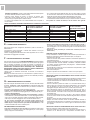
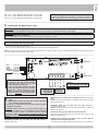
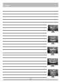
SELF-TEST-ENABLED RIB ELECTRONIC BOARD CHART
RIB ELECTRONIC BOARD
CONNECT A/D+ TEST TERMINAL
TO TERMINAL
ENABLE SELF-TEST FUNCTION
THROUGH
K2007 / K2007 CRX
S1
T2 - T2 CRX
T2 24V - T2 24V CRX
J - J CRX
BOSS 24V CRX
BOSS 230V CRX
A+ TEST
A+ TEST
D+ TEST
A+ TEST
D+ TEST
Terminal 8
Terminal 8
DIP 10
DIP 12
DIP 13
DIP 12
DIP 7
DIP 6
DIP 6
E - MASTER Wi-Fi POWER
After having made all of the connections, provide power to the control panel with
MASTER Wi-Fi.
The yellow LED DL6 should come on and the buzzer will emit a sound indicating
correct power.
The LED DL7 will alternately flash red and green indicating that no remote controls
or blinkers have been memorized.
F - IDENTIFICATION OF SAFETY DEVICES
Every Wi-Fi safety device must OBLIGATORILY be identified placing only one
of the 6 micro-switches present on its circuit (different for each of the 6 safety
devices) in the ON position. Obviously one pair of photocells is considered one
safety device and must therefore have a receiver and transmitter with the same
DIP in the ON position.
IDENTIFY THE CONTAINERS OF THE SAFETY DEVICES WITH THE NUMBER
OF THE ACTIVATED MICRO-SWITCH AND ATTACH THE NUMBERED
ADHESIVE STRIP SUPPLIED TO THE OUTSIDE OF EACH CONTAINER.
The adhesive strip serves as a means of quickly identifying the safety device when
it needs maintenance.
Note: Each safety device is supplied with the micro-switches in the OFF position
so that battery power is not consumed when not in use (if inserted).
Insert the batteries in the Wi-Fi safety devices.
G - MEMORIZATION OF THE SAFETY DEVICES
After having performed the identification of the safety devices, and provided power
with the batteries, place the micro-switches with the same number of the safety
devices on the MASTER Wi-Fi in the ON position to activate the safety devices
to be memorized.
Use the following procedure for memorization:
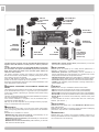
- Push the button PROG RX on the MASTER Wi-Fi => dual-color LED EDGE
PHOT 1 flashes red for 1 minute (the time needed for memorization).
- Push the button PROG TX on the safety device with micro-switch 1 in
the ON position => on the MASTER Wi-Fi the dual-color LED EDGE PHOT 1
flashing red turns green and a sound from the buzzer indicates that the safety
device has been memorized correctly, immediately the dual-color LED EDGE
PHOT 2 begins flashing red.
- If there are no other safety devices to be memorized after one minute the
dual-color LED EDGE PHOT 2 will turn off or, push the button PROG. RX 4
times to end the memorization procedure => all of the dual-color LED EDGE
PHOT should be off.
MEMORIZATION OF OTHER SAFETY DEVICES
- After having memorized the first safety device, the dual-color LED EDGE
PHOT 2 automatically begins flashing red for 1 minute (the time needed for
memorization).
- Push the button PROG. TX on the safety device with micro-switch 2 in the ON
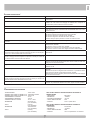
PLACE JUMPER JP1 ON
THE MASTER WI-FI CARD IN
POSITION:
+/~
+/~
+/~
+/~
+/~
JP1
+/~
+/~
+/~
osition => on the MASTER Wi-Fi the dual-color LED EDGE PHOT 2 flashing
p
red turns green and a sound from the buzzer indicates that the safety device has
been memorized correctly.
- Follow the same procedure for any other safety devices (up to a maximum of 6).
ADDING OTHER SAFETY DEVICES (UP TO 6 TOTAL)
If after installation the use of further safety devices (PHOTOCELLS OR STRIPS)
is desired, to increase door safety, it is recommended to:
- Turn off power to the door.
- Place the safety device in the desired position and identify it by moving the
internal micro-switch.
- Perform the programming by setting to ON a micro-switch different from that of
the other safety devices installed and identify it with the corresponding numbered
adhesive strip (see paragraph F - IDENTIFICATION OF Wi-Fi SAFETY
DEVICES).
- Enable the micro-switch of the safety device just added on the MASTER Wi-Fi
card.
- Return power to the door.
- Follow the memorization procedure and system check as indicated previously.
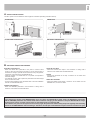
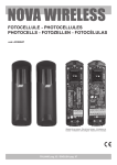
NOVA Wi-Fi AND VERTIGO PHOTOCELLS SYSTEM CHECK
- Check that the micro-switch selected on the transmitter TX NOVA Wi-Fi is the
same as that selected on the receiver RX NOVA Wi-Fi (example 1 ON).
- Proper function of the TX NOVA Wi-Fi is shown by the green LED which comes
on for 10 seconds.
- Push and release the button S3 “PROG. TX” on the NOVA Wi-Fi receiver (it
activates for 3 minutes to perform the alignment procedure). If the photocells are
already aligned the red LED emits a constant light. If the red LED is off or emits
a flashing light, perform the alignment until it emits a constant light.
- After the alignment check by placing an obstacle that the red LED turns off and
that at the same time the dual-color LED EDGE PHOT associated with it during
memorization shines green on the MASTER Wi-Fi for the time that the obstacle
is present.
- On the MASTER Wi-Fi card, LED DL3 should also be off indicating a proper
exchange of the dedicated input with the PHOT on the control panel.
- Repeat the procedure on the other installed NOVA Wi-Fi photocells.
- Perform a function check of all the installed photocells, activating the movement
of the automation and checking that by placing an obstacle the automation stops/
reverses when closing, or stops/continues to open when opening.
TOUCH Wi-Fi STRIP SYSTEM CHECK
After having calibrated the TOUCH Wi-Fi strip correctly:
- Push the contact of a TOUCH Wi-Fi strip (for example: safety device number 3).
- On the MASTER Wi-Fi check that the corresponding LED EDGE PHOT 3 flashes
green and that the paired LED DL2 momentarily turns off and then turns on.
ATTENTION: after receiving the first signal, other signals are ignored for 2
seconds. If there is a signal in these 2 seconds it will be from the LED EDGE
PHOT 3 which turns green.
14