1
Options a and b: the diameter of the spigot housing the
fresh air flow controller is 125 mm.
The 16.6 1/s (60 m3/h) fresh air controller may be modified
on site by relocating or removing two plastic restrictors in
order to increase the maximum constant fresh air flow
capacity to 44.4 1/s (160 m3/h). A label on the 42EM shows
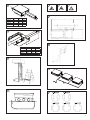
how to adjust the two plastic restrictors (Fig. 11).
Modification procedure
•Disconnect the fresh air duct from the spigot on the
Atmosphera.
•Remove or reposition the two plastic restrictors,
following the fresh air flow controller.
•Reconnect the fresh air duct to the spigot.
IMPORTANT: If the Atmosphera is fitted with a return
air temperature sensor, the constant fresh air flow rate
must not exceed 50% of the supply air flow delivered by
the unit at minimum speed.
NOTE: To operate correctly, the 8.3 l/s (30 m3/h) constant
fresh air flow controller requires a differential pressure in
the range 50 Pa to 200 Pa. The 16.6 l/s (60 m3/h) constant
fresh air controller requires a differential pressure in the
range 70 to 200 Pa.
4.5.2 - Fresh air controller with variable air volume
The 42EM Atmosphera can be equipped with an optional
variable fresh air flow controller from 0 to 55 l/s (0 to 200
m3/h).
This is connected to the numeric Carrier controller and
can regulate the fresh air intake in two ways:
• either using a fixed rate set by the installer that can be
reconfigured as required
• or based on the CO2 level; in this case it is connected
to a CO2 sensor via the Carrier numeric controller
(the CO2 sensor is located opposite the fresh air inlet).
NOTE: With the variable fresh air flow controller the
upstream pressure in the fresh air duct must be 180 Pa.
4.6 - Optional water flow control valves
These valves are two-way or four-way type, with a body
designed to withstand a 16 bar operating pressure.
4.6.1 - Electrothermal actuator (on/off)
The actuator is a 230 V a.c. on/off type.
To enable the installation to be filled with water, the
water circuits to be equalised and the units to be purged,
the actuators must be connected to the power supply to
open the valves via a command from the wall thermostats
or from the BMS.
4.6.2 - Actuator replacement procedure
The actuators on both the chilled water and the hot water
valves may be replaced if either develops a fault.
• Disconnect the power supply to the unit before carrying
out any work on a unit.
• Disconnect the actuator power supply cable.
-230 V on/off type actuator used with the Carrier
numeric controller: Disconnect the actuator
power supply cable fitted with a quick connector.
-230 V on/off actuator used with an electronic
thermostat: Remove the plastic protection cover
held in place with two screws. Disconnect the
actuator power supply cable connected to the
quick connector. This can be done by pressing
down the spring tongue using a screwdriver and
pulling out the wire from the appropriate terminal.
• Uncouple the faulty actuator. Refitting is by the reversal
of the procedure described above.
WARNING: Ensure that the actuator is firmly screwed to
the valve body (maximum torque 15 N·m).
4.6.3 - Valve body replacement procedure
•Disconnect the power supply before carrying out any
work on a unit.
• Close the isolating valves on the manifolds.
•Unscrew the union nuts to disconnect the flexible water
pipes.
•Remove the valve actuators taking care to identify the
cooling and heating valves.
•Disconnect the flexible condensate drain pipe which is
held in place by a collar (the collar is not supplied by
Carrier).
•Remove the two-way or four-way water flow control
valve bodies. Depending how the Atmosphera is configured, the four-way valve coupling may be fitted with
a heating/cooling changeover switch, if so do not
remove it.
•Remove the 4 torx screws (T20) and slide out the coil
and drain pan assembly.
•Fit the new valve body to the coil (fit new gaskets).
• Refit the coil and condensate assembly.
•Reconnect the flexible condensate drain pipe which is
held in place by a collar (the collar is not supplied by
Carrier).
•Refit the valve actuators taking care to ensure that
they are correctly fixed to the valve body.
•Reconnect the flexible water pipes by tightening the
union nuts. Retighten all the water connections and
ensure that all gaskets have been changed and correctly
fitted (maximum torque 15 N·m).
•Open the isolating valves on the manifolds and purge
all air from the system.
• Check that there are no leaks and reconnect the power
to the Atmosphera.
WARNING: When replacing a valve always ensure that
the direction of flow through the valve is as shown by the
arrow on the valve body. If the direction of flow is wrong,
the valve body will deteriorate rapidly.
11