1
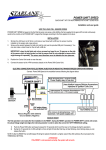
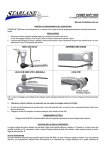
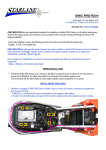
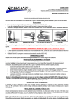
POWER SHIFT-VX
QUICK SHIFT KIT FOR DIRECT SHIFT LEVER MOTORBIKES
Installation and user guide
HOW THE VX SENSOR WORKS
POWER SHIFT VX is based on the fact that its patented sensor can sense, while shifting, the deformation of the lever on the point where it’s
locked to the shaft.
The sensor replaces the fixing bolt of the lever and continuously sends to the control unit of POWER SHIFT a signal that changes according to
the force applied on the lever.
LEVER PREPARATION
To allow a correct working of the sensor it’s necessary to prepare the factory
lever following the operations as below:
1.
Perforate the lever with a 6,5mm drill to remove
the thread completely and to widen the part without
any thread.
2.
Verify that the in and out surfaces are flat, often you need to flatten
the out surface of the factory bolt (black area in the picture) with a
file, because both the head of the sensor and the nut have to be on
a flat surface with no bumps.
SENSOR ORIENTATION
Sensor orientation is the most important parameter for the correct working of the system. As for your parabolic aerial, a correctly oriented sensor
allows to get a high signal that will produce consistent working and much setting accuracy while a sensor which is not well oriented can give a so
low signal that the system becomes unusable.
In most bikes the VX sensor must be installed so that the axis of the cable is perfectly aligned with the longitudinal one of the bike. In the
ATTACHED SCHEME are listed the mountig modes for the most common bike models.
NOTE: The ideal sensor orientation can change due to the installed lever and its material, it’s possibile to find out the best orientation for your
lever executing completely the settings below indicated (from RESET to SENSITIVITY SETTING) with the sensor oriented in different directions;
the best orientation will be the one for which you can set the highest value on the selector to reach the correct working.
SENSOR MOUNTING
1)
2)
3)
4)
5)
6)
Insert the previously prepared lever on the shaft.
Insert the sensor following the instructions above.
Apply the supplied nut with integrated washer.
Screw the sensor to the normal torque for 6mm bolts. (About 10 Nm.), don’t hesitate in screwing the sensor for a good tightening will
produce a high quality signal while a not enough tightened sensor can output a low and not good signal.
Don’t insert any washer between the sensor or the nut and the lever because they could highly decrease the signal.
Verify that the head of the sensor touches the lever only through the round face and not through other points or edges of the head, if
that happens remove the exceeding material on the lever to completely eliminate the wrong contact.
ELECTRIC CONNECTION
Connect Power Shift VX to the motorbike harness choosing, on the attached diagram, the A or B connection mode for your motorbike type.
SENSOR RESET
The first operation to be made after the installation and every time the sensor is removed and reinstalled, or its locking torque is
changed, is the RESET. During the RESET operation the POWER SHIFT control unit senses the actual screwing torque value and
aligns the internal parameter in order to allow the correct CUT OFF THRESHOLD setting.
1)
2)
Move a little bit the lever by hand in an oscillating repeated mode Up and Down ( never reaching the engage level) in order to clear
some possible forces in the lever metal after the sensor mounting and in order to allow the pairing to be mechanically relaxed.
Push the Power Shift button and keep it pressed for 10 seconds.
3)
During the 10 seconds the 2 LEDs will light on than will light off and after that they will start blinking, when blinking stops you can
release the button.
NOTE: If after the RESET the red LED keeps ON bring the selector threshold to a higher value till the LED switches off and proceed to the
THRESHOLD SETTING .
ATTENTION!
If the RESET is not executed correctly each time the sensor is thightened on the lever, the system will not work.
SETTING THE CUT OFF THRESHOLD
The force at which you wish the system to cut off is set by the 16 steps selector on which the minimum value (high sensitivity) is indicated by ”0”,
setting a higher value will result in a stickly behaviour of the lever till the maximum value reached on the ”F” position.
Working direction
Power Shift can sense the force in both the lever directions, so Power Shift will work in upshifting like in downshifting, anyway it’s possible to limit
the intervention in just one direction executing the following operations:
1.
2.
3.
Switch off Power Shift.
Press the pushbutton and keep it pressed meanwhile you power on the unit, the 2 LEDs will light on for 1 second, don’t release the
pushbutton.
Always keeping pressed the pushbutton, after 10 seconds one LED will light on (ex. GREEN) to show the system has been set to
work in just one direction afterwords, when the LED turns off release the pushbutton. Repeating the same steps, the next time the
other LED (ex. RED) will light on, in this case the system will work in the opposite direction, if you ulteriorly redo the operation both the
LEDs will light on to show the system has been set to work bidirectionally, the direction setting can be repeated at will without any limit.
The sensitivity setting explained below must be executed only for the upshifting and not the downshifting direction.
Setting the Sensitivity
While the engine is off move by hand the gearshift lever, in upshift direction, till you feel the gear “sticking”, the red LED must light on just while
you are feeling the “stickness”, if the red LED keeps off move the selector anticlockwise, if it lights on before the gear is engaged move it in
cloclwise direction.The correct setting is reached when the red LED lights on at the moment of the gear engaging, the green LED lighting on
means the cut off has happened.
It’s suggested to optimize the setting after a drive test; in order to void the intervention being influenced by possibile dumps, vibrations or
unwanted actions by the rider, the optimal setting is always reached looking for the highest value on the selector, set the selector to increasing
values till the force on the lever during the ride is too high, then lower the slector value by 1 step. So its always necessary to opt for a higher
threshold if you notice undesired cuts or possibile gears coming out after a shifting, if the correct threshold setting on your motorbike is equal or
higher than 4-5 it means the sensor installation is outputting a good signal, in the case you had to set te selector to lower values we suggest you
to find out a different sensor orientation because the signal could be not optimal, once you change the sensor orientation you must make the
sensor reset again.
SETTING THE CUT OFF TIME
The Cut Off time is preset at an optimal value for the most part of the engines at 5 hundreths of second (50 milliseconds), anyway it’s possible to
set it at will between 3 and 15 hundreths of second.Keeping the button pressed for at least 3 seconds you enter the Cut Off setting mode,
realease the button as soon as both the LEDs light on. The LEDs will blink as many times as the hundreths of second actually set, after a 1
second pause they repeat the same sequence.
During the blinking sequence push the button as many times as the desired hundreths to be set.
Ex: with the factory setting of 5 hundreths of second the LEDs execute 2 sequences of 5 blinks separated by a 1 second pause. In order to set
the Cut Off time of 4 hundreths, during the blinking, press the button 4 times, the LEDs will execute two sequences of 4 blinks and the procedure
will be completed.
INVERTING THE ELECTRIC CONTACT TYPE (normally opened-normally closed)
Note: In the case it should be necessary, for particular applications, to invert the cut contact, follow the steps below:
(Attention: before making this operation verify the electrical connections because the contact inversion could damage the motorbike
electronics, harness or some fuses).
1.
2.
3.
4.
5.
Power on Power Shift.
Move the selector to the “F” position.
Press and keep pressed the button for 30 seconds, during this time the 2 LEDs will light on, light off and in a while just one will light on
(Green or Red depending on the contact type just set).
Release the button.
Position the selector on the previous value you found out for the correct threshold setting.
Power Shift is covered by a 12 month warranty against manufacturing defects.- not homologated for pubblic road use
Starlane s.r.l. Via Madonna delle Rose, 70 - 24061 Albano S. Alessandro (BG) - Italia - Tel. +39 035-4521007 Fax +39 035-4528208
e-mail:[email protected]
http://www.starlane.com
POWER SHIFT-VX
KIT CAMBIO ELETTRONICO PER MOTO CON LEVA DIRETTA
Manuale d’installazione ed uso
PRINCIPIO DI FUNZIONAMENTO DEL SENSORE VX
POWER SHIFT VX basa il suo funzionamento sul suo sensore coperto da brevetto che è in grado di rilevare la deformazione della leva del
cambio nel punto di fissaggio sull’albero millerighe durante l’azionamento da parte del pilota.
Il sensore sostituisce il bullone di fissaggio della leva e invia continuamente alla centralina POWER SHIFT un segnale che varia in funzione della
forza applicata sulla leva.
PREPARAZIONE DELLA LEVA
Per consentire al sensore di funzionare correttamente è necessario preparare appositamente la leva del cambio originale eseguendo le
operazioni illustrate di seguito:
1.
Forare in modo passante la leva del cambio
con una punta da 6,5mm in modo
da eliminare completamente il filetto e portare
a diametro maggiorato la parte di foro non filettata.
2.
Verificare che sulla leva le zone di entrata e uscita del foro
presentino una superficie piana, spesso può essere necessario
spianare con una lima la faccia di uscita del bullone originale
(indicata in nero nell’immagine) per far sì che sia la testa del
sensore che il dado di bloccaggio appoggino su una superficie
piana e priva di bombature.
ORIENTAMENTO DEL SENSORE
L’ orientamento del sensore è il parametro più importante per il funzionamento del sistema. Come per un’antenna parabolica, un sensore
orientato correttamente consente il rilevamento di un forte segnale che darà un’ottima costanza di funzionamento e molta precisione nella
regolazione mentre un sensore orientato in modo scorretto può dare un segnale talmente basso da rendere il sistema inutilizzabile.
Nella maggior parte dei modelli di moto il sensore VX deve essere installato in modo che l’asse di uscita del cavo sia perfettamente in linea con
l’asse longitudinale della moto, nella TABELLA ALLEGATA sono elencate le modalità di montaggio per i modelli più diffusi.
N.B.: L’ orientamento ideale del sensore può variare in funzione della leva installata e del suo materiale, è possibile individuare
sperimentalmente il miglior orientamento per la vostra leva eseguendo completamente le tarature sotto indicate (da RESET a REGOLAZIONE
DELLA SENSIBILITÀ) con il sensore orientato in sensi diversi; la soluzione migliore sarà quella per la quale sarà stato impostato il valore più
alto sul selettore per il corretto inserimento della marcia.
MONTAGGIO DEL SENSORE
1)
2)
3)
4)
5)
6)
Inserire sull’alberino del cambio la leva precedentemente preparata.
Inserire il sensore seguendo le indicazioni sopra riportate.
Applicare il dado con rondella integrata fornito in dotazione.
Serrare il sensore alla normale coppia di serraggio per bulloni da 6mm. (Circa 1,2 Kgm.), non esitare a serrare il sensore in quanto un
buon serraggio si tradurrà in un segnale di buona qualità mentre un sensore non sufficientemente serrato può dare un segnale scarso
e poco affidabile.
Evitare di inserire rondelle tra il sensore o il dado e la leva in quanto potrebbero ridurre nettamente il segnale rilevato.
Verificare che la testa del sensore sia a contatto con la leva solo attraverso la corona circolare e non ci siano altri punti o spigoli della
testa in contatto, in tal caso asportare leggermente il materiale in eccesso sulla leva finchè il contatto indesiderato non sia
completamente eliminato.
CONNESSIONE ELETTRICA
Collegare Power Shift VX all’impianto elettrico della moto scegliendo attentamente sullo schema allegato la modalità di connessione A o B in
funzione del tipo di moto.
RESET DEL SENSORE
La prima operazione da effettuare dopo l’installazione ed ogni volta che il sensore viene rimosso e rimontato, o ne viene variata la
coppia di serraggio, è il RESET. Durante l’operazione di RESET la centralina POWER SHIFT rileva il valore a cui è stato serrato il
sensore e azzera i parametri in modo da consentire la corretta regolazione della soglia d’intervento.
1)
2)
3)
Muovere leggermente la leva con la mano in modo ripetuto verso l’alto e il basso (senza mai arrivare all’inserimento delle marce) per
eliminare eventuali tensioni del metallo della leva dopo il serraggio e far sì che si assesti l’accoppiamento sull’alberino.
Premere il pulsante di Power Shift e mantenerlo premuto per 10 secondi.
Durante i 10 secondi i due LED si accendono poi si spengono e successivamente iniziano a lampeggiare velocemente, al termine del
lampeggio rilasciare il pulsante.
N.B.: Se dopo il Reset resta acceso il LED rosso portare la soglia del selettore ad un valore maggiore finchè il LED non sarà spento e procedere
con la Taratura Della Soglia.
ATTENZIONE!
Se il RESET non è eseguito adeguatamente ogni volta che il sensore viene serrato sulla leva, il sistema non funzionerà correttamente.
TARATURA DELLA SOGLIA D’INTERVENTO
La forza alla quale si desidera che intervenga il taglio viene impostata attraverso il selettore a 16 posizioni la cui soglia minima (più sensibile) è
indicata con ”0”, aumentando il valore si aumenta la durezza il cui valore massimo è raggiunto con la lettera ”F”.
Verso di funzionamento
Power Shift Speed è in grado di rilevare la forza in entrambi i versi di azionamento della leva, con l’impostazione di fabbrica Power Shift interverrà sia in
inserimento che in scalata, è comunque possibile limitare l’intervento a una delle due direzioni eseguendo le operazioni di seguito riportate:
1.
2.
3.
Togliere alimentazione a Power Shift.
Premere il pulsante e mantenerlo premuto mentre si da alimentazione, si accenderanno i 2 LED per un secondo, non rilasciare il
pulsante.
Mantenendo sempre premuto il pulsante, dopo circa 10 secondi si accenderà un solo LED (es. VERDE) a indicare che il sistema è
stato impostato per intervenire solo in un verso dopodiché, allo spegnimento del LED rilasciare il pulsante.Ripetendo la stessa
operazione, la volta successiva si accenderà l’altro LED (es. ROSSO), in tal caso il sistema interverrà nel verso opposto, se
l’operazione viene eseguita ulteriormente si accenderanno entrambi i LED ad indicare che il sistema è stato impostato in modo
bidirezionale, l’operazione di impostazione del verso può essere ripetuta a piacere senza limiti.
La regolazione della sensibilità di seguito specificata dovrà essere comunque eseguita per il verso di inserimento e non di scalata.
Regolazione della sensibilità
A motore spento azionare con la mano la leva del cambio, nel senso di inserimento, fino a che si sente “puntare” la marcia, il LED rosso deve
attivarsi non appena raggiunto tale “puntamento”, se il LED rosso resta spento ruotare il selettore in senso antiorario, se invece si attiva prima
che la marcia punti ruotarlo in senso orario. La taratura è corretta se il LED rosso si attiva nell’esatto istante del “puntamento”, l’accensione del
LED verde indica l’avvenuto taglio di corrente.
E’ consigliabile ottimizzare la taratura dopo una prova su strada; per evitare che l’intervento sia influenzato da eventuali sobbalzi, vibrazioni o
azioni involontarie del pilota, la taratura ottimale si ottiene cercando sempre il valore di durezza maggiore, impostare il selettore a valori crescenti
finchè lo sforzo sulla leva durante la cambiata diventa eccessivo, dopodiché riabbassare il valore del selettore di un 1 punto. E’ quindi
necessario optare sempre per una soglia più alta se si notano tagli di corrente indesiderati o l’eventuale accidentale uscita di una marcia dopo la
cambiata, se l’impostazione della sensibilità corretta per la vostra moto è di valore uguale o superiore alla posizione 4-5 del selettore significa
che il montaggio del sensore sta dando un buon segnale, nel caso in cui dobbiate regolare il selettore su posizioni più basse è consigliabile
provare a installare il sensore con un orientamento diverso da quello scelto in quanto il segnale può non essere ottimale, una volta variato
l’orientamento effettuare nuovamente il RESET.
REGOLAZIONE DEL TEMPO DI TAGLIO (CUT OFF)
Il tempo di Cut Off è pre-impostato ad un valore ottimale per la maggior parte dei motori pari a 5 centesimi di secondo (50 millisecondi), in ogni
caso è possibile impostarlo a piacere da 3 a 15 centesimi di secondo. Tenendo premuto il pulsante per almeno 3 secondi si entra in modalità
programmazione del tempo di Cut Off, rilasciare il tasto appena si illuminano entrambi i LED. I LED lampeggiano tante volte quanti sono i
centesimi di secondo impostati, dopo una pausa di 1 secondo ripetono tale sequenza.
Durante la sequenza di lampeggi premere il pulsante tante volte quanti sono i centesimi di secondo che si vogliono impostare.
Es: con l’impostazione di fabbrica di 5 centesimi di secondo i LED eseguono 2 sequenze di 5 lampeggi separate dalla pausa di 1 secondo. Per
impostare il tempo a 4 centesimi , durante i lampeggi, premere quattro volte il pulsante, i LED eseguiranno quindi due sequenze di 4 lampeggi e
la procedura sarà terminata.
INVERSIONE DEL CONTATTO DI AZIONAMENTO (normalmente aperto-normalmente chiuso)
N.B: Nel caso in cui fosse necessario, per applicazioni particolari, invertire il contatto di azionamento, eseguire le operazioni di
seguito riportate:
(Attenzione: prima di effettuare tale operazione verificare le connessioni elettriche perché l’inversione del contatto potrebbe
danneggiare l’impianto o i fusibili)
1.
2.
3.
4.
5.
Alimentare Power Shift.
Posizionare il selettore sulla lettera “F”.
Premere e mantenere premuto il pulsante per circa 30 secondi, durante tale tempo i 2 LED si accendono, si spengono e successivamente
se ne riaccenderà solo uno (Verde o Rosso a seconda del tipo di azionamento appena impostato).
Rilasciare il pulsante.
Riposizionare il selettore sul valore precedentemente individuato nella fase di taratura.
Power Shift è coperto da garanzia 12 mesi su difetti di fabbricazione – non omologato per uso stradale
Starlane s.r.l. Via Madonna delle Rose, 70 - 24061 Albano S. Alessandro (BG) - Italia - Tel. +39 035-4521007 Fax +39 035-4528208
e-mail:[email protected]
http://www.starlane.com
POWER SHIFT-VX
KIT CAMBIO ELETTRONICO PER MOTO CON LEVA DIRETTA
QUICK SHIFT KIT FOR DIRECT LEVER MOTORBIKES
SCHEMA DI MONTAGGIO DEL SENSORE VX
VX SENSOR MOUNTING DIAGRAM
A
B
C
YAMAHA YZF
HONDA CRF
SUZUKI DRZ
HUSKVARNA
APRILIA SXV-RXV *
* Sulle moto con leva del
cambio in ferro il sensore
non deve essere serrato
eccessivamente ma
solamente il necessario
affinché la leva non abbia
gioco sull’alberino, un
eccesso di serraggio
risulterà in un segnale di
bassa qualità.
*On the bikes with iron
lever the sensor must not
be tightened excessively
but only the minimum
necessary to void
the lever sliding on the
shaft, tightening it too
much will result in a bad
quality signal.
D
E
SCHEMA DI COLLEGAMENTO ELETTRICO
ELECTRIC CONNECTION DIAGRAM