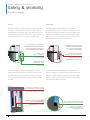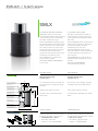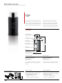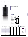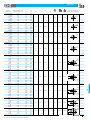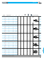
1
pantone 312 U
pantone 7545 U
Cilindri all’azoto per stampi
RUN-tech and X-tech series
ma
ly
True quality lives in time
La vera qualità si esprime nel tempo
100%
Nitrogen gas springs for dies
a
de in it
Nitrogen gas springs for dies / Cilindri all’azoto per stampi
1
L’azienda Bordignon
Bordignon company
2
Active since 1958, Bordignon was the first company producing
Attiva dal 1958, Bordignon è stata la prima realtà produttrice
springs for molds and nitrogen gas springs to have obtained the
di molle per stampi e cilindri all’azoto ad aver ottenuto
UNI EN ISO 9002 certificate for the implementation of the Quality
la Certificazione UNI-EN ISO 9002 per l’applicazione del Sistema
System to its production process, totally inside the company and
Qualità al suo processo produttivo, totalmente interno e controllato
controlled at every stage, from the acceptance of raw materials to
in ogni fase, dall’accettazione delle materie prime sino allo
the storage of the finished product.
stoccaggio del prodotto finito.
Besides commitment to quality, the company adds the constant
All’impegno sulla qualità l’azienda aggiunge la costante ricerca di
search for innovative solutions to provide specific answers to the
soluzioni innovative per fornire risposte specifiche alle più diverse
most diverse use conditions.
condizioni di utilizzo.
pantone 312 U
pantone 7545 U
Service and technological creativity:
Bordignon makes the difference
Servizio e creatività tecnologica:
così Bordignon fa la differenza
Taking care of the customer needs is the starting point for
Dal confronto con le esigenze dei propri clienti, Bordignon trae
Bordignon research, which is aimed at offering customized nitrogen
i motivi della sua ricerca, tesa a proporre cilindri personalizzati
gas springs in a market characterized by standard solutions. That’s
in un mercato caratterizzato da soluzioni standard. Nascono
how dedicated products, perfect blends of nano-technologies
così prodotti ad hoc, perfetti insiemi di nano-tecnologie e nuovi
and new materials synthesis, are designed to ensure safety and
materiali di sintesi, pensati per assicurare sicurezza nelle
reliability over time, generating quality in the production processes
prestazioni e affidabilità nel tempo, generatori di qualità nei
in which they are involved.
processi produttivi in cui vengono coinvolti.
Safety, research and development, production with no outsourcing,
Sicurezza, ricerca e sviluppo, produzione senza outsourcing,
quality, big stock for quick delivery, have always been the points of
qualità, grande disponibilità a magazzino per consegne veloci,
strength of the Bordignon company.
contraddistinguono da sempre l’azienda Bordignon.
Nitrogen gas springs for dies / Cilindri all’azoto per stampi
3
4
Cilindri all’azoto per stampi, programma di produzione
Nitrogen gas springs for dies
Production program
pantone 312 U
pantone 7545 U
CILINDRI ALL’azoto per stampi:
» 2 series of self-contained gas springs with nano-technology: CSX, SMLX;
» 2 serie di cilindri autonomi con nano-tecnologia: CSX, SMLX;
» 5 series of self-contained gas springs: C, CSM, TOP, CISO, CVDI;
» 5 serie di cilindri autonomi: C, CSM, TOP, CISO, CVDI;
» not self-contained gas springs for connection to an open system;
» cilindri non autonomi per collegamento a sistema;
» gas springs without valve for connection to plate (OV);
» cilindri senza valvola per collegamento a piastra (OV);
» gas springs for MANIFOLD systems;
» cilindri non autonomi per piastra forata (MANIFOLD);
» high temperature gas springs (up to 200°C / 392°F);
» cilindri per alta temperatura (fino a 200°C / 392°F);
» slow-return gas springs on request;
» cilindri rallentati a richiesta;
» timed gas springs on request;
» cilindri temporizzati a richiesta;
» special gas springs on request;
» cilindri speciali a richiesta;
» lifters charged with nitrogen (EG).
» espulsori caricati con azoto (EG).
» lifters with wire spring (EM).
» espulsori a molla (EM).
RUN-tech and X-tech series
ma
ly
100%
Nitrogen gas springs for dies:
a
de in it
Nitrogen gas springs for dies / Cilindri all’azoto per stampi
5
Sicurezza e affidabilità, i nostri punti di forza
Safety & reliability
Our points of strength
Safety
Sicurezza
Bordignon nitrogen gas springs have always been built with single
Da sempre i cilindri all’azoto Bordignon sono costruiti con
(‘monolithic’) thick mechanical components, in order to ensure
componenti meccanici singoli (“monolitici”) di elevato spessore,
product integrity and maximum user’s safety even under the most
per garantire l’integrità del prodotto e la massima sicurezza per
extreme wrong use conditions (collisions, etc.). The piston rod is
l’utilizzatore anche nelle più estreme condizioni di errato utilizzo
blocked by a thick mechanical stop inside the cylinder body.
(collisioni, ecc.). Lo stelo è bloccato da un fermo meccanico di
elevato spessore all’interno del corpo del cilindro.
SINGLE ‘MONOLITHIC’ COMPONENTS
BORDIGNON CONSTRUCTION
SEVERAL ASSEMBLED COMPONENTS
OTHER CONSTRUCTIONS
SINGOLI COMPONENTI “MONOLITICI”
VARI COMPONENTI ASSEMBLATI
COSTRUZIONE BORDIGNON
ALTRE COSTRUZIONI
MORE THAN
DOUBLE THICKNESS
GROOVE FOR LOCK RING
SENSIBLY REDUCES THICKNESS
SPESSORE
PIU’ CHE DOPPIO
LA SEDE PER L’ANELLO
DI BLOCCAGGIO RIDUCE
SENSIBILMENTE LO SPESSORE
PISTON ROD THICK
MECHANICAL STOP
SPESSO FERMO MECCANICO
DELLO STELO
Bordignon nitrogen gas springs have always been built with a
Da sempre i cilindri all’azoto Bordignon sono realizzati con un
safety system for both internal over-pressure and over-stroke:
sistema di sicurezza in caso di extra-corsa o di pressione interna
the cylinder body metal wall is thinner at the bottom and gets
eccessiva: la parete metallica del corpo del cilindro è più sottile
deformed in such critical conditions, allowing a safe gas spring
alla base e si deforma in tali condizioni critiche, consentendo lo
discharge.
scaricamento del cilindro in sicurezza.
PROBLEM 1: EXCESSIVE STROKE
COLLISION AGAINST THE GAS SPRING
PROBLEMA 1: CORSA ECCESSIVA
COLLISIONE CONTRO IL CILINDRO
PROBLEM 2: EXCESSIVE PRESSURE
INSIDE THE GAS SPRING
PROBLEMA 2: PRESSIONE ECCESSIVA
ALL’INTERNO DEL CILINDRO
6
METAL WALL DEFORMATION LEADS
TO SAFE DISCHARGE IN BOTH CASES
LA DEFORMAZIONE DELLA PARETE
METALLICA PORTA ALLO
SCARICAMENTO IN SICUREZZA
IN ENTRAMBI I CASI
pantone 312 U
pantone 7545 U
Bordignon gas spring components are coupled through thread
I componenti dei cilindri Bordignon sono assemblati tramite filetti,
connections, for the highest possible safety. Thread connections
per assicurare la massima sicurezza possibile. Accoppiamenti
are standard in high pressure equipment around the world, such as
tramite filetti sono uno standard su apparecchiature ad alta
waterjet cutting nozzles and ultra high pressure vessels (~10000
pressione in tutto il mondo, come ad esempio ugelli per il taglio ad
bar).
acqua e recipienti a pressione ultra-elevata (~10000 bar).
GAS SPRING CYLINDER BODY
CORPO DEL CILINDRO
THREAD CONNECTION
ACCOPPIAMENTO CON FILETTO
GAS SPRING BOTTOM CAP
TAPPO DEL CLINDRO
performance
prestazioni
All Bordignon nitrogen gas springs (except for the TOP series) are
Tutti i cilindri all’azoto Bordignon (tranne la serie TOP) sono
self-lubricated, thanks to a solid lubricant (PATENT PENDING).
autolubrificati, grazie a un lubrificante solido (PATENT PENDING).
SOLID LUBRICANT
LUBRIFICANTE SOLIDO
Nitrogen gas springs for dies / Cilindri all’azoto per stampi
7
Potenza e compattezza, i nostri punti di forza
Power & compactness
Our points of strength
POWER & COMPACTNESS
POTENZA E COMPATTEZZA
Bordignon produces various series of nitrogen gas springs, for
Bordignon produce diverse serie di cilindri all’azoto, per qualsiasi
every dimensional demand. Other than our ISO 11901 nitrogen gas
esigenza dimensionale. Oltre alla nostra serie di cilindri all’azoto
spring line (Bordignon CISO series), we offer many other higher-
a norma ISO 11901 (serie Bordignon CISO), offriamo molti altri
performance models, with forces up to +300% higher and with
modelli dalle prestazioni più elevate, con forze fino al +300%
much more compact dimensions.
maggiori e con dimensioni molto più compatte.
WIRE SPRINGS (LOW POWER)
MOLLE A FILO (FORZA CONTENUTA)
Reduction of die size translates into cost reduction and higher
La riduzione delle dimensioni dello stampo si traduce in riduzione
productivity, with advantages for both the die-maker and the
dei costi e migliore produttività, con vantaggi sia per lo stampista
die-user.
che per lo stampatore.
ISO 11901 GAS SPRINGS (BIG SIZE, LOW POWER)
CILINDRI ISO 11901 (INGOMBRO ELEVATO, FORZA CONTENUTA)
8
GAS SPRINGS (HIGH POWER)
CILINDRI ALL’AZOTO (FORZA ELEVATA)
BORDIGNON HIGHER-POWER GAS SPRINGS
(COMPACT SIZE, HIGH POWER)
CILINDRI BORDIGNON CON FORZA INCREMENTATA
(DIMENSIONI COMPATTE, FORZA ELEVATA)
Qualità certificata
Certified quality
pantone 312 U
pantone 7545 U
I cilindri Bordignon sono affidabili e durano a lungo poiché
guarantee the longest service life: they are the end result of many
sono il risultato di anni d’esperienza, ricerca e innovazione,
years of experience, research and innovative technology rewarded by
premiate dalla CERTIFICAZIONE UNI-EN ISO 9001.
the UNI EN ISO 9001 CERTIFICATION. More than 600 nitrogen gas
Il catalogo presenta oltre 600 cilindri autonomi già
springs have been standardized and listed in this catalogue: they’re in
caricati e pronti all’uso, normalmente a magazzino per una
stock for immediate delivery, charged and ready for use.
rapida consegna.
Bordignon also produces tailor made nitrogen gas springs on
A richiesta vengono forniti cilindri e sistemi di cilindri
request.
non standard.
THE BORDIGNON NITROGEN GAS SPRINGS, IF PROPERLY USED, WILL
SE CORRETTAMENTE USATI, I CILINDRI BORDIGNON HANNO UNA
LAST MORE THAN 100.000.000 mm OF TOTAL STROKE.
DURATA DI OLTRE 100.000.000 mm DI CORSA TOTALE.
SYSTEM CERTIFICATION
RUN-tech and X-tech series
ma
ly
100%
The Bordignon nitrogen gas springs are designed and built to
a
de in it
Nitrogen gas springs for dies / Cilindri all’azoto per stampi
9
Istruzioni per l’uso
Use instructions
no
No side forces. Work stroke always perpendicular to
No forze laterali. Corsa di lavoro perpendicolare alla
the base of the nitrogen gas spring.
base del cilindro.
Avoid scratching and scoring on the piston rod.
Non scalfire o rigare lo stelo.
N2
Do not make mechanical work on the nitrogen gas
Non eseguire lavorazioni meccaniche sul cilindro.
spring.
10
Do not disassemble the nitrogen gas spring.
Non smontare il cilindro. Manutenzione solo da
Maintenance only by authorized people.
personale autorizzato.
Max impact and max release speed: 1 m/s
Massima velocità d’impatto e di rilascio: 1 m/s
(TOP series: 0.5 m/s).
(serie TOP: 0,5 m/s).
Do not freely release the piston rod. The piston rod
Non rilasciare liberamente lo stelo. Accompagnarlo
goes up together with the press.
con la pressa.
Protect against liquid or solid contaminants.
Proteggere da emulsioni di stampaggio, detergenti,
The nitrogen gas springs are protected against
acqua e polveri. I cilindri sono protetti da contaminanti
contaminants by scraper ring (except for the TOP
con raschiastelo di protezione (tranne le serie TOP e
series, EG series, CISO19 and CISO25 models).
EG e i modelli CISO19 e CISO25).
Do not use chemical products with low flash point
Non usare prodotti chimici con basso flash point
(petrol, solvents, alcohol, etc.).
(benzine, solventi, alcool, ecc.).
Clean only with a dry cloth.
Pulire solo con un panno asciutto.
pantone 312 U
pantone 7545 U
yes
N2
N
N22
N
2
N
N22
Always fasten the nitrogen gas spring at the base to a flat
Fissare sempre il cilindro alla base con viti ad alta
and clean support surface with high resistance screws.
resistenza su superficie piana e pulita.
Gas springs with more than one threaded hole at the
Cilindri con più di un foro filettato alla base: il foro
base: the center hole is for charging/discharging only.
centrale è adibito al solo caricamento/scaricamento.
Use all the other holes at the base for fixing.
Usare tutti gli altri fori alla base per il fissaggio.
Charge only with NITROGEN (N2).
Caricare solo con AZOTO (N2 ).
Hole for cylinder body Ø + 1mm.
Foro per cilindro Ø +1 mm.
Draining hole for liquids.
Foro di scarico per liquidi.
Lubricate the piston rod with grease with disulfide
Lubrificare lo stelo con grasso con bisolfuro di
molybdenum (MoS2).
molibdeno (MoS2 ).
Operating temperature:
Temperatura di lavoro:
MIN 0°C (32°F) - MAX 80°C (176°F)
MIN 0°C (32°F) - MAX 80°C (176°F)
Do not heat.
Non riscaldare.
Protect against liquid contaminants by a polimeric
Proteggere da emulsioni di stampaggio, detergenti e
bellow, solid contaminants by a metal bellow.
acqua con soffietto polimerico, da polveri con soffietto
metallico.
Information
» Stroke available at 100%
» You might adjust the initial force with the charging and
discharging set (model COMPL)
» Charging pressure: MIN 30 bar - MAX see table
» How to calculate the charging pressure (bar) for initial forces
(daN) lower than Finitial in table:
Charging pressure (bar) =
F (daN) × max charging pressure (bar)
Finitial in table
» How to calculate the force (daN) at intermediate strokes:
F = Finitial +
intermediate stroke
× (Ffinal - Finitial)
max stroke
» Corsa utilizzabile al 100%
»Forza iniziale regolabile con il set di carico e scarico
(modello COMPL)
»Pressione di carico: MIN 30 bar - MAX vedere tabella
» Calcolo della pressione di carico (bar) per forze iniziali (daN)
minori della Finiziale in tabella:
Pressione di carico (bar) =
F (daN) × pressione massima di carico (bar)
Finiziale in tabella
» Calcolo della forza (daN) a corse intermedie:
F = Finiziale +
corsa intermedia
× (Ffinale - Finiziale)
corsa massima
Nitrogen gas springs for dies / Cilindri all’azoto per stampi
11
Nano-tecnologia
Nano-technology
RUN-tech and X-tech
Patent pending
RUN-tech and X-tech series
Both nano-technologies RUN-tech and X-tech are present on the
Entrambe le nano-tecnologie RUN-tech e X-tech sono presenti sui
models CSX and SMLX. The nano-technology RUN-tech allows to
modelli CSX e SMLX. La nano-tecnologia RUN-tech permette di
double the self-lubrificated SPM. The advantage for the die-user
raddoppiare gli SPM senza lubrificazione. Il vantaggio per l’utilizzatore
is to halve the time of each batch production and of the work-in-
è il dimezzamento del tempo di ogni lotto di produzione e di impegno
press time. The nano-technology X-tech allows to increase, in a
pressa. La nano-tecnologia X-tech permette di incrementare,
considerable way, the nitrogen gas springs durability in case of
in modo notevole, la durata dei cilindri in caso di corsa dello stelo
piston rod stroke not perpendicular to the base*. The tests were
non perpendicolare alla base*. Sono stati testati cilindri con corse fino
performed with strokes up to 80 mm. The advantage for the
a 80 mm. Il vantaggio per l’utilizzatore e lo stampista è l’eliminazione
die-user and for the die-maker is the elimination of production-
dei fermi di produzione dovuti ad anomalie costruttive o di utilizzo
stops because of press-die manufacture anomalies or use
dello stampo.
anomalies.
* The nitrogen gas springs with the nano-technology X-tech passed the
durability test of 1 Million shots with piston rod eccentricity of 1° (1.76 mm
/ 100 mm). The nitrogen gas springs proper use is with piston rod stroke
perpendicular to the base and with the nitrogen gas springs fixed at the base.
The durability is longer with piston rod stroke perpendicular to the base.
* Con la nano-tecnologia X-tech i cilindri hanno superato il test di 1 milione
di colpi con inclinazione dello stelo pari a 1° (1,76 mm / 100 mm). L’utilizzo
corretto dei cilindri è con corsa dello stelo perpendicolare alla base e con i
cilindri fissati alla base. La durata è maggiore con corsa perpendicolare alla
base.
INITIAL FORCE DECREASE (%)
CALO FORZA INIZIALE (%)
20
INCLINATION
INCLINAZIONE
SHOTS NUMBER
NUMERO DI COLPI
STROKE
CORSA
MODEL
MODELLO
Durability test result / Risultato dei test di durata
CSX 19-25
25 mm 200 spm
0°
SMLX 25-25
25 mm 200 spm
0°
0
-20
-40
-60
-80
-100
0 0,51,01,52,0
SHOTS NUMBER (MILLIONS)
NUMERO DI COLPI (MILIONI)
50 spm
35 mm
70 spm
INCLINATION
INCLINAZIONE
48 mm
20
1°
(1,76 mm / 100 mm)
1°
(1,76 mm / 100 mm)
[The graphs show reference values / I grafici mostrano valori di riferimento]
12
INITIAL FORCE DECREASE (%)
CALO FORZA INIZIALE (%)
SMLX 38-38
SHOTS NUMBER
NUMERO DI COLPI
CSX 32-50
STROKE
CORSA
MODEL
MODELLO
Durability test result / Risultato dei test di durata
0
-20
-40
-60
-80
-100
0
0,25
0,5
SHOTS NUMBER (MILLIONS)
NUMERO DI COLPI (MILIONI)
0,75
1,0
Product range
RUN-tech / X-tech series
Nitrogen gas springs for dies / Cilindri all’azoto per stampi
RUN-tech and X-tech series
Ø
CSX
STROKE / CORSA mm
mm
daN
daN
19
150
240
25
300
480
32
500
800
38
1000
1600
50
2000
3200
63
3000
4800
75
5000
8000
95
8000
12800
5
Max. strokes number per min. without lubrication
Colpi max/min. senza lubrificazione
SMLX
CSX
10
13
15
25
38
50
63
•
•
•
•
•
•
•
•
•
•
•
•
•
•
•
•
•
•
•
•
•
•
•
•
•
•
•
•
•
•
•
•
•
•
•
•
•
•
•
•
•
•
•
•
•
•
•
•
•
•
•
•
•
•
•
•
500
335
200
130
100
80
65
C
CSM
TOP
Ø
smlx
EG
80
100
125
TOP 12 20
160
200
CVDI
CIS
STROKE / CORSA mm
mm
daN
daN
5
10
25
300
600
32
500
1000
38
750
1500
50
1500
3000
63
????
????
75
3000
6000
95
5000
10000
•
•
•
•
•
•
•
•
•
•
•
•
•
•
Max. strokes number per min. without lubrication
Colpi max/min. senza lubrificazione
MIC
SMLX
75
CSMF
C
1000 500
CSM
EM
13
15
•
•
•
•
•
•
•
CF
335
TOP
25
38
50
63
75
80
• • •
•
• • •
•
• • •
•
• • •
•
Product
• in •development
• / Prodotto in sviluppo
•
• • •
•
• • •
•
200
130
100
CT 38
TOP 12 20
65
100
125
160
200
•
•
•
•
50
CSMT 38
CVDI
CSM HT
CISO
OV
Nitrogen gas springs for dies / Cilindri all’azoto per stampi
13
X
CSMF
Product range
STANDARD series
Nitrogen gas springs for dies / Cilindri all’azoto per stampi
Ø
C
STROKE / CORSA mm
mm
daN
daN
19
150
240
25
300
480
32
500
800
38
750
1200
50
1500
2400
63
2000
3200
75
3000
4800
95
5000
8000
120
9000
14400
Max. strokes number per min. with lubrication
Colpi max/min. con lubrificazione
Max. strokes number per min. without lubrication
Colpi max/min. senza lubrificazione
C
CSM
5
10
15
25
38
50
•
•
•
•
•
•
•
•
•
•
•
•
•
•
•
•
•
•
•
•
•
•
•
•
•
•
•
•
•
•
•
•
•
•
•
•
•
•
500
335
200
130
100
200 120 80
TOP
12 20
60
TOP
300
5
10
13
Ø
CSM
daN
daN
19
150
240
25
300
480
32
500
800
38
750
1200
50
1500
2400
63
2000
3200
75
3000
4800
95
5000
8000
120
9000
14400
•
•
•
•
•
•
•
CT 38
Colpi max/min. con lubrificazione
Max. strokes number per min. without lubrication
Colpi max/min. senza lubrificazione
500
TOP 12 20300
TOP
13
15
EM
14
80
100
125
160
200
•
•
•
•
•
•
•
•
•
•
•
•
•
•
•
•
•
•
•
•
•
•
•
•
•
•
•
•
•
•
•
•
•
•
80
65
50
40
30
25
50
CVDI
40
CISO30
25
20
15
125
160
200
•
•
•
•
•
•
•
•
•
•
25
38
50
•
•
•
•
•
•
•
•
•
CSMT 38
•
•
•
•
•
•
•
•
•
•
•
•
•
• •
• •
• •
• •
•CSM•HT
•
•
•
•
335
200
130
200
CVDI
120
80
Ø
TOP
75
STROKE / CORSA mm
mm
CF
Max. strokes number per min. with lubrication
CSM
63
63
75
80
•
•
•
•
•
•
•
•
•
100
• •
• •
• •
• •
•C HT•
100
80
65
50
40
30
25
60
CISO
50
40
30
25
20
15
80
100
125
160
200
STROKE / CORSA mm
mm
daN
daN
12
50
80
14
75
120
16
100
160
20
200
320
Max. strokes number
per min. with lubrication
Colpi max/min.
con lubrificazione
5
OV
10
13
15
•
•
•
•
•
•
•
•
250
165
25
38
50
63
75
pantone 312 U
pantone 7545 U
Ø
TOP
VDI
mm
daN
daN
5
25
400
640
32
700
1120
38
1000
1600
50
2000
3200
63
3000
4800
75
4000
6400
95
7000
11200
120
10000
16000
Max. strokes number per min. with lubrication
Colpi max/min. con lubrificazione
TOP
VDI 3003
CVDI
12 20 ISO CVDI
11901
8
STROKE / CORSA mm
CISO
CT 38
TOP 12 20
CISO
15
25
•
•
•
•
•
•
•
•
•
•
•
•
•
•
•
•
•
•
•
•
•
•
•
•
•
•
•
•
•
•
•
•
250
165
100
50
CVDI
13
38
50
63
75
80
100
125
160
200
80
100
125
160
200
200
CISO
Ø
STROKE / CORSA mm
mm
daN
daN
15
25
38
50
63
19
90
144
•
•
•
•
•
•
•
•
•
•
•
•
25
200
320
•
•
Max. strokes number
per min. with lubrication
Colpi max/min.
con lubrificazione
335
200
130
100
80
65
50
40
Max. strokes number
per min. without lubrication
Colpi max/min.
senza lubrificazione
200
120
80
60
50
40
30
25
5
10
13
80
100
125
160
•
•
•
•
•
•
•
•
•
•
•
•
•
•
•
Ø
CISO
mm
75
STROKE / CORSA mm
daN
19 38100
CSMT
daN
5
10
160 CSM
HT
•
•
•
•
25
200
320
32
150
195
38
250
325
45
500
650
50
750
1125
75
1500
2250
95
3000
4500
120
5000
7500
150
7500
11250
Max. strokes
CSMnumber
HT per min. with lubrication
C HT
Colpi max/min. con lubrificazione
Max. strokes number per min. without lubrication
Colpi max/min. senza lubrificazione
OV
10
13
•
16
25
38
50
63
C• HT•
•
•
•
•
•
•
•
•
•
•
•
•
•
•
•
•
•
•
•
•
•
•
•
•
•
•
•
•
•
•
•
•
•
•
•
•
•
•
•
•
•
•
•
•
•
•
•
•
•
•
•
•
•
•
•
•
•
•
•
75
500
385
315
200
130
100
80
70
65
50
40
30
300
230
190
120
80
60
50
40
40
30
25
20
Nitrogen gas springs for dies / Cilindri all’azoto per stampi
15
LX
Product range
OTHER series
CSX
Nitrogen gas springs, nitrogen gas ejectors, spring ejectors
Cilindri all’azoto, espulsori a gas azoto, espulsori a molla
DESCRIPTION / DESCRIZIONE
MIC
SMLX
CSX
C
CSX
C
SMLXCSM
Flanged gas springs
Cilindri flangiati
CT
Threaded-body gas springs
CSMF
Cilindri con corpo filettato
MIC
CSX
TOP 12 20
TOP
TOP
C TOP
DESCRIPTION / DESCRIZIONE
CF
SM
CSM
CSM
TOP 12 20
CSMF
SMLX
CVDI
CISO
CHT
High temperature gas springs
Cilindri per alta temperatura
EG
CF
200°C
392°F
CSMF
SMLX
CRAL
200°C
OV 392°F
Slow-return gas springs
CSMF
C HT
MIC
OV
Nitrogen gas ejectors
Espulsori a gas
OV
EM OV
EM
EM
TOP
C HT
CSMF
CVDI
CSM
SMLX
High temperature
compact gas springs
CT 38 CSM
Cilindri compatti
per alta temperatura
HT CSMT 38C HT
EM
CT 38
Valveless gas springs
CSMF
EM Wire spring ejectors
Espulsori a molla
CSMT 38
CSM HT
CT 38
OV
OV
OV
16
EG
EG EM
CISO
EG
CF
CF
TOP 12
CTOP
CT 38 Cilindri senzaCSMT
valvola 38
CSMF MIC
EG
EG
CF
MIC
EG
MAX TEMPERATURE
MIC
CSMT Cilindri
38 a ritorno
CSM
HT
MIC
CSMF
rallentato
EGEG
EM
CSX C
CSMHT
CF
CSMT 38
EM
MAX TEMPERATURE
CT 38
CT 38
compact gas springs
Cilindri compatti
TOP
TOP 12 20
con corpo filettato
CSM
C
TOP
CISO
12 20
C Threaded-body CSM
CSMT 38 MIC
CSM HT
SMLX
CT 38
C
TOP
CVDI
Flanged compact gas springs
Cilindri flangiati compatti
CSMT
CSX
CF
CSX
CSMFMIC
Ready-to-use ø 25 mm
gas springs with different
initial forces
Cilindri
all’usoCVDI
ø 25 mm SMLX
TOP 12pronti
20CSX
CISO
con diverse forze iniziali
EMOV
CF CS
Uso del catalogo
Catalogue help
HOW TO ORDER
COME ORDINARE
You order (example): No. 8 CSX38-25
Ordinate (esempio): N° 8 CSX38-25
You receive: 8 pieces CSX series nitrogen gas springs, ready
for use, diameter Ø 38 mm, stroke 25 mm, initial force
1000daN (other specifications on CSX series page).
Ricevete: 8 cilindri ad azoto serie CSX, pronti per l’uso,
diametro Ø 38 mm, corsa 25 mm, forza iniziale 1000daN
(altre specifiche sulla pagina della serie CSX).
ATTENTION: we have enhanced the force of the C- and CSMtype gas springs (C, CSM, CF, CSMF, CT, CSMT). Whenever
ordering these gas springs, always specify the required initial
force!
ATTENZIONE: abbiamo aumentato la forza dei cilindri tipo C e
CSM (C, CSM, CF, CSMF, CT, CSMT) Quando ordinate questi
cilindri specificate sempre la forza richiesta!
Examples:
No. 8 CSM50-25 1500daN
if you want the new higher-force CSM.
No. 8 CSM50-25 1000daN
if you want the old lower-force CSM.
Esempi:
N° 8 CSM50-25 1500daN
se volete i nuovi CSM con forza incrementata.
N° 8 CSM50-25 1000daN
se volete i vecchi CSM con forza minore.
Special solutions: different forces and strokes (not on
catalogue) are available on request.
Soluzioni speciali: forze e corse diverse da quelle a catalogo
sono disponibili a richiesta.
Gas spring accessories
Accessori per cilindri
Accessories for fixing, charging/discharging, linking to open
system, etc. can be found in our ‘Accessories for nitrogen gas
springs’ catalogue.
Accessori per fissaggio, carico/scarico, collegamento
a sistema, ecc. sul nostro catalogo ‘Accessori per cilindri
all’azoto’.
ATTENTION: use Bordignon nitrogen gas springs with
Bordignon accessories only.
ATTENZIONE: usare i cilindri all’azoto Bordignon solamente con
accessori Bordignon.
2D & 3D Technical drawings
Disegni tecnici 2D e 3D
download various 2D & 3D file formats from
www.bordignon.com
vari formati 2D e 3D scaricabili dal sito
www.bordignon.com
Nitrogen gas springs for dies / Cilindri all’azoto per stampi
17
RUN-tech / X-tech series
Nitrogen gas springs for dies / Cilindri all’azoto per stampi
CSX
RUN-tech and X-tech series
The compactpower: forces up to
4 times the ones of the corresponding
ISO 11901 standard gas springs and up
to 50% more than the corresponding gas
springs of our series “C” and “CSM” (old
models). Therefore you may save a lot of
space and money by manufacturing more
compact press-dies!
Self-lubricated: by activated solid
lubricant (patent pending).
Protected against contaminants:
by rod scraper.
I COMPATTOPOTENTI: a pari dimensioni
hanno forza fino a 4 volte quella dei
corrispondenti standard ISO 11901
e circa 50% in più dei corrispondenti della
serie “C” e “CSM” (vecchi modelli). Pertanto
consentono un RISPARMIO DI SPAZIO E
COSTI costruendo stampi più compatti!
AUTOLUBRIFICATI: per milioni di cicli con
lubrificante solido energizzato (in corso
di brevetto).
PROTETTI DA CONTAMINANTI:
con raschiastelo di protezione.
TECHNICAL NOTES
NOTE TECNICHE
Important use instructions
on pages 10 & 11
Importanti istruzioni d’uso
alle pagine 10 e 11
For accessories
and other mountings,dsee
Thread for maintenance
Filetto per manutenzione
the ‘Accessories
for nitrogen gas springs’
M
Scraper ring
catalogue.
Per accessori e altri montaggi,
consultare
Lubrificante
solido
il catalogo ‘Accessori per cilindri
all’azoto’
.
Piston
rod guides
CSX
N
Gas holding seal
Guarnizione di tenuta
L
Mechanical stop
Fermo meccanico
Mechanical stop
CSX model.
Holding valve
Valvola di tenuta
O-ring
Guarnizione OR
Nitrogen feeding hole
Foro alimentazione azoto
O-ring
Guarnizione OR
Nitrogen feeding hole
Foro alimentazione azoto
D
Gas holding seal
Guarnizione di tenuta
Corse di lavoro diverse a richiesta
stop
(ad esempio corsa 125 mm).Mechanical
Fermo meccanico
Holding valve
Il modello CS è sostituibile con
il
Valvola di tenuta
modello CSX.
L
Fermo meccanico
Holding valve
Valvola di tenuta
Guide dello stelo
N
Piston rod guides
Guide dello stelo
Anello raschiastelo
Solid lubricant
Lubrificante
solido on request
Different
work strokes
Piston rod guides
(for example
125
mm stroke).
Guide dello stelo
Gas holding seal
tenuta
The CS Guarnizione
model isdireplaceable
with the
H
2mm
Solid lubricant
Lubrificante solido
Scraper ring
Anello raschiastelo
Solid lubricant
Stroke
Corsa
Stroke
Corsa
Scraper ring
Anello raschiastelo
Thread for maintenance
Filetto per manutenzione
1mm
H
Thread for maintenance
Filetto per manutenzione
d
M
O-ring
Guarnizione OR
G1/8 side hole
Foro laterale G1/8
Nitrogen feeding hole
Foro alimentazione azoto
D
SPECIAL VERSION
VERSIONE SPECIALE
Special cap with groove and G1/8 side hole,
linkable to open system, from ø 50 mm.
» L and N dimensions: + 20 mm
»Add an -S to order them
Example: no. 8 pcs CSX50-50-S
Da ø 50 mm tappo speciale con scanalatura e
foro laterale G1/8, per collegamento a sistema.
» Quote L e N: + 20 mm
» Per ordinarli, aggiungere una -S
Esempio: n° 8 CSX50-50-S
20
Special version
18
d
CSX
CSX
RUN-tech / X-tech series
MODEL
MODELLO
MAX STROKE mm
CORSA MAX mm
L
mm
N
mm
D
mm
d
mm
M
19
10
M5
H
mm
bar
daN
daN
7
191
150
240
GAS SPRING BASE
BASE DEL CILINDRO
CSX19-10
10
65
75
15
15
70
85
25
25
80
105
38
38
97
135
50
50
110
160
63
63
127
190
M6
M6
M6
80
80
140
220
10
65
75
15
15
70
85
25
25
80
105
38
38
97
135
50
50
110
160
63
63
127
190
M6
M6
M6
M4
M6
M6
M6
M6
25
14
M6
8
195
300
480
M6
M6
80
80
145
225
CSX32-10
10
65
75
15
15
70
85
25
25
80
105
38
38
97
135
50
50
110
160
63
63
132
195
80
80
150
230
15
20
CSX38-10
10
65
75
15
20
15
15
70
85
25
25
80
105
38
38
97
135
15
15
20
M6
M4
2 x M6
M6
M4
2 x M6
M6
M4
2 x M6
M4M8
2 x M6
M8
M4
22 xx M6
M6
M8
M4
22 xx M6
M6
M4M8
2
x
M6
2 x M6
M8
M8
20
20
22 xx M6
M6
M8
M8
15
32
18
M8
12
197
500
800
15
15
15
20
38
25
M8
12
205
1000
1600
50
50
110
160
63
63
142
205
80
80
160
240
20
20
22xxM6
M8
M8
M8
CSX50-10
10
80
90
20
20
22 xx M6
M8
M8
20
20
22 xx M6
M8
M8
20
20
22xxM6
M8
M8
20
20
22 xx M8
M8
M8
15
15
100
115
25
110
135
38
38
127
165
50
35
M8
12
209
2000
3200
50
50
140
190
63
63
157
220
80
80
175
255
20
20
22 xx M8
M8
M8
CSX63-10
10
85
95
20
20
15
15
100
115
2
M8
2 xx M8
M8
25
25
110
135
20
40
22 xx M8
M8
M8
20
40
2 x M8
4 x M8
M8
20
40
2 x M8
M8
4 x M8
M8
38
38
127
165
50
50
140
190
63
63
157
220
80
80
175
255
20
40
2 x M8
4 x M8
M8
CSX75-10
10
90
100
15
15
110
125
40
60
2 x M8
4 x M8
M8
25
25
120
145
40
60
M8
44 xx M8
M8
38
38
137
175
40
60
44 xx M8
M8
M8
63
40
60
44 xx M8
M8
75
45
58
M8
M8
12
12
189
190
3000
5000
4800
8000
50
50
150
200
63
63
177
240
80
80
195
275
60
44 xx M8
M8
60
4 x M8
M8
60
4 x M8
M8
60
4 x M8
CSX95-10
10
100
110
15
15
120
135
25
25
130
155
38
38
147
185
50
50
165
215
63
63
192
255
80
80
210
290
pantone 7545 U
M6
CSX25-10
25
pantone 312 U
95
75
M8
12
182
8000
12800
4 x M8
Nitrogen gas springs for dies / Cilindri all’azoto per stampi
19
Nitrogen gas springs for dies / Cilindri all’azoto per stampi
SMLX
IL PIU’ BASSO E PIU’ POTENTE
DAL 2001: estremamente compatti con
minimo ingombro in altezza e forza fino a
3 volte quella dei corrispondenti standard
ISO 11901.
PER LO STAMPISTA: cilindri con diametri ed
altezza minori permettono la realizzazione
di stampi più compatti, riducendo
notevolmente tutti i vostri costi.
PER L’UTILIZZATORE: cilindri con lunga
durata permettono la drastica riduzione dei
costi di manutenzione sugli stampi e dei
fermi macchina.
AUTOLUBRIFICATI: per milioni di cicli con
lubrificante solido energizzato (in corso di
brevetto).
PROTETTI DA CONTAMINANTI:
con raschiastelo di protezione.
TECHNICAL NOTES
NOTE TECNICHE
Different work
strokes on request.
Mechanical stop
Corse di lavoro diverse a richiesta.
Piston rod guides
1mm
Per accessori e altri montaggi, consultare
Scraper ring
il catalogo ‘Accessori per cilindri all’azoto’
.
Anello raschiastelo
N
L
Solid lubricant
Lubrificante solido
N
Fermo meccanico
L
Mechanical stop
Fermo meccanico
O-ring
Guarnizione OR
Holding valve
Valvola di tenuta
G1/8 side hole
Foro laterale G1/8
Nitrogen feeding hole
Foro alimentazione azoto
D
Guide dello stelo
holding seal
Il modello SML è sostituibile con ilGasmodello
Guarnizione di tenuta
SMLX.
The SML model
is replaceable with the
Holding valve
SMLX model.Valvola di tenuta
Holding valve
Valvola di tenuta
O-ring
Guarnizione OR
Nitrogen feeding hole
Foro alimentazione azoto
Thread for maintenance
Filetto per manutenzione
Lubrificante
solido mountings, see
For accessories
and other
Pistonfor
rod nitrogen
guides
the ‘Accessories
gas springs’
Guide dello stelo
catalogue.
Gas holding seal
Guarnizione di tenuta
H
Mechanical stop
Fermo meccanico
Importanti istruzioni d’uso
alle pagine 10 e 11
H
Solid lubricant
d
M
Stroke
Corsa
Scraper ring
Anello raschiastelo
Solid lubricant
Lubrificante solido
Piston rod guides
Guide dello stelo
Gas holding seal
Guarnizione di tenuta
d
M
Stroke
Corsa
Thread for maintenance
Filetto per manutenzione
Important useScraper
instructions
ring
on pages 10 Anello
& 11 raschiastelo
Thread for maintenance
Filetto per manutenzione
RUN-tech and X-tech series
THE SHORTEST AND MOST POWERFUL
SINCE 2001: extremely compact with
minimum height clearance and with forces up
to 3 times the ones of the corresponding
ISO 11901 standard gas springs.
FOR THE DIE-MAKER: nitrogen gas springs
with reduced diameters and reduced lengths
allow to manufacture more compact pressdies, cutting in drastic way all your costs.
FOR THE DIE-USER: nitrogen gas springs
with long durability allow the drastic
cutting of the costs generated by press-die
maintenance and production stops.
SELF-LUBRICATED: by activated solid
lubricant (patent pending).
PROTECTED AGAINST CONTAMINANTS:
by rod scraper.
SMLX
1mm
O-ring
Guarnizione OR
D
Nitrogen feeding hole
Foro alimentazione azoto
SPECIAL VERSION
VERSIONE SPECIALE
Special cap with groove and G1/8 side hole,
linkable to open system, from ø 50 mm.
» L and N dimensions: + 20 mm
»Add an -S to order them
Example: no. 8 pcs SMLX50-50-S
Da ø 50 mm tappo speciale con scanalatura e
foro laterale G1/8, per collegamento a sistema.
» Quote L e N: + 20 mm
» Per ordinarli, aggiungere una -S
Esempio: n° 8 SMLX50-50-S
Special version
20
20
d
e
N
RUN-tech / X-tech series
d
SMLX
SMLX25-05
10
•
MAX STROKE mm
CORSA MAX mm
L
mm
N
mm
5
35
40
10
40
50
15
15
45
60
25
25
55
80
38
38
68
106
50
50
80
130
80
80
110
190
•
10 •
5
35
40
SMLX32-05
10
40
50
15
15
45
60
25
25
55
80
38
38
68
106
50
50
80
130
80
80
110
190
•
10 •
5
35
40
10
40
50
15
15
45
60
25
25
55
80
38
38
68
106
50
50
80
130
80
80
110
190
5
40
45
SMLX38-05
SMLX50-05
10
•
10
45
55
15
15
50
65
25
25
60
85
38
38
73
111
50
50
85
135
80
80
120
200
100
100
135
235
D
mm
d
mm
M
25
14
M6
H
mm
bar
daN
daN
8
195
300
600
GAS SPRING BASE
BASE DEL CILINDRO
M6
32
18
M6
8
196
500
1000
M6
M6
M6
M6
M8
M8
M6
M8
38
22
M6
8
197
750
1500
M6
M8
M10
M10
M8
M10
M8
M10
50
30
M8
12
212
1500
3000
M??
M??
M10
M??
M10
M??
M12
25
Product in development / Prodotto in sviluppo
38
50
M12
M??
M12
M??
M12
80
100
•
5
45
50
10
50
60
15
15
55
70
25
25
65
90
38
38
77
115
50
50
90
140
80
80
125
205
100
100
145
245
•
5
55
60
10
60
70
15
15
65
80
25
25
75
100
38
38
88
126
50
50
100
150
80
80
130
210
100
100
150
250
10
M6
M6
M6
15
SMLX95-05
pantone 7545 U
M6
10
10
pantone 312 U
M6
SMLX63-05
SMLX75-05
SMLX
MODEL
MODELLO
RUN-tech / X-tech series
M12
M12
M12
75
45
M8
12
189
3000
6000
M12
M12
M12
M12
M12
95
58
M8
12
189
5000
10000
• The piston rods don’t have the threaded hole / Gli steli non hanno il foro filettato
Nitrogen gas springs for dies / Cilindri all’azoto per stampi
21
Standard series
Nitrogen gas springs for dies / Cilindri all’azoto per stampi
C
NUOVA SERIE C POTENZIATA NELLE FORZE
DEL 50% pur conservando le stesse
dimensioni esterne della vecchia serie.
Ora con scanalatura da ø 50 mm. Tutta
la serie è autolubrificata e protetta da
contaminanti con raschiastelo di protezione.
New C series 50% more powerful
than the old one even mantaining the
same overall dimensions. Now with groove
from ø 50 mm. The complete series is
self-lubricated and protected against
contaminants by rod scraper.
C
d
M
N
L
Nitrogen feeding hole
Foro alimentazione azoto
D
Nitrogen feeding hole
Foro alimentazione azoto
D
TECHNICAL NOTES
NOTE TECNICHE
Important use instructions
on pages 10 & 11
For accessories and other mountings, see
the ‘Accessories for nitrogen gas springs’
catalogue.
Importanti istruzioni d’uso
alle pagine 10 e 11
Per accessori e altri montaggi, consultare
il catalogo ‘Accessori per cilindri all’azoto’.
How to order
Esempio d’ordine
8 C38-50 750daN
No. 8 nitrogen gas springs C ø 38 mm,
stroke 50 mm, initial force 750 daN
Solid lubricant
(new model).
Lubrificante solido
ATTENTION: specify the required force
8 dC38-50 750daN
N° 8 cilindri all’azoto C ø 38 mm,
corsa 50 mm, forza iniziale 750 daN
(nuovo modello).
ATTENZIONE: indicare la forza desiderata
STANDARD VERSION
VERSIONE STANDARD
Piston rod guides
Guide dello stelo
Gas holding seal
Guarnizione di tenuta
Ready with cap with groove
and G1/8 side
Mechanical stop
hole, linkable to open system,
from ø 50 mm.
Fermo meccanico
Holding valve
Valvola di tenuta
Stroke
Corsa
20
Stroke
Corsa
1mm
Guarnizione OR
Scraper ring
Anello raschias
Solid lubricant
Lubrificante soli
Piston rod guid
Guide dello stel
Gas holding sea
di t
Pronta da ø 50 mm con tappo con scanalaturaGuarnizione
e
Mechanical stop
con foro laterale G1/8 per collegamento a sistema.
Fermo meccani
N
Holding valve
22Valvola di tenuta
r
O-ring
L
Mechanical stop
Fermo meccanico
Holding valve
Valvola di tenuta
1mm
D
N
Gas holding seal
Guarnizione di tenuta
Mechanical stop
Fermo meccanico
G1/8 side hole
Foro laterale G1/8
L
Piston rod guides
Guide dello stelo
Gas holding seal
Guarnizione di tenuta
O-ring
Guarnizione OR
P
Solid lubricant
Standard
version
Lubrificante
solido
Piston rod guides
Guide dello stelo
L
Holding valve
Valvola di tenuta
d
Scraper ring
Anello raschiastelo
Solid lubricant
Lubrificante solido
N
Mechanical stop
Fermo meccanico
Holding valve
Valvola di tenuta
O-ring
Guarnizione OR
Nitrogen feeding hole
Foro alimentazione azoto
1mm
Gas holding seal
Guarnizione di tenuta
H
Mechanical stop
Fermo meccanico
d
M
Thread for maintenance
Filetto per manutenzione
Scraper ring
Anello raschiastelo
Piston rod guides
Guide dello stelo
Stroke
Corsa
Scraper ring
Anello raschiastelo
Solid lubricant
Lubrificante solido
Piston rod guides
Guide dello stelo
Gas holding seal
Guarnizione di tenuta
Solid lubricant
Lubrificante solido
1mm
Thread for maintenance
Filetto per manutenzione
H
Scraper ring
Anello raschiastelo
d
M
Stroke
Corsa
Thread for maintenance
Filetto per manutenzione
Holding valve
Valvola di tenuta
C
Standard series
C19-10
15
25
38
50
80
C25-10
15
25
38
50
80
C32-10
15
25
38
50
80
C38-10
15
25
38
50
80
C50-10
25
38
50
63
80
100
125
160
200
C63-10
25
38
50
63
80
100
125
160
200
C75-10
25
38
50
63
80
100
125
160
200
C95-25
38
50
63
80
100
125
160
200
C120-25
38
50
63
80
100
125
160
200
•
•
•
•
•
•
•
•
•
•
•
•
•
•
•
•
•
•
•
•
•
•
•
•
•
•
•
•
•
•
•
•
•
•
•
•
•
•
•
MAX STROKE mm
CORSA MAX mm
L
mm
N
mm
10
15
25
38
50
80
10
15
25
38
50
80
10
15
25
38
50
80
10
15
25
38
50
80
10
25
38
50
63
80
100
125
160
200
10
25
38
50
63
80
100
125
160
200
10
25
38
50
63
80
100
125
160
200
25
38
50
63
80
100
125
160
200
25
38
50
63
80
100
125
160
200
70
75
85
98
110
140
70
75
85
98
110
140
60
65
75
88
100
130
65
70
80
93
105
140
95
110
123
135
148
165
195
220
255
295
95
110
123
135
148
165
185
220
255
295
105
120
133
145
158
175
200
225
265
310
130
143
155
168
190
210
245
280
330
140
153
165
178
195
215
250
290
340
80
90
110
136
160
220
80
90
110
136
160
220
70
80
100
126
150
210
75
85
105
131
155
220
105
135
161
185
211
245
295
345
415
495
105
135
161
185
211
245
285
345
415
495
115
145
171
195
221
255
300
350
425
510
155
181
205
231
270
310
370
440
530
165
191
215
241
275
315
375
450
540
D
mm
d
mm
M
19
10
M5
25
14
M6
H
mm
bar
daN
daN
7
191
150
240
8
195
300
GAS SPRING BASE
BASE DEL CILINDRO
18
M8
12
196
500
800
38
22
M8
12
197
750
1200
pantone 7545 U
M8
M8
M8
M8
M8
M8
M8
M8
M8
M8
M8
M8
M8
480
32
pantone 312 U
C
MODEL
MODELLO
M8
M8
M8
M8
M8
M8
M8
M8
M8
M8
M8
M8
M8
M8
M8
M8
M8
50
30
M8
12
212
1500
2400
20
20
20
20
20
20
20
20
20
20
20
20
20
20
63
36
M8
12
196
2000
3200
20
20
20
40
20
40
40
40
40
80
M8
24 xxM8
M8
4 x M8
M8
4 x M8
4 xM8
M8
4 x M8
M8
M8
4 xM8
M8
M8
M8
4x
M8
4 x M8
4 xM8
M8
M8
44 xxM8
M8
4 x M8
4 xM8
M8
4 x M8
M8
M8
M8
4 xM8
M8
M8
4 x M8
4 x M8
4 x M10
M8
44xxM10
M8
4 x M10
M8
4 x M10
M8
4 x M10
M8
4 x M10
80
4 x M10
40
75
45
M8
12
189
3000
4800
40
40
60
60
40
60
60
60
60
60
95
58
M8
12
189
5000
8000
60
80
80
60
80
80
80
80
80
120
75
M8
•Without G1/8 side hole and groove / Senza foro laterale G1/8 e scanalatura
•Available on request / Disponibili a richiesta
12
204
9000
14400
M8M8
M8
M8
M8
M8M8
2 xM8
M8
2 x M8
M8
2 x M8
2 xM8
M8
2 x M8
M8
2 x M8
M8
M8
2 x M8
M8
M8
2 x M8
M8
2
x
M8
22 xxM8
M8
2 xM8
M8
2 xM8
M8
2 x M8
M8
2 x M8
M8
M8
M8
2 x M8
M8
2 x M8
M8
4 x M10
4 x M10
Nitrogen gas springs for dies / Cilindri all’azoto per stampi
23
Standard series
Nitrogen gas springs for dies / Cilindri all’azoto per stampi
CSM
NUOVA SERIE CSM POTENZIATA NELLE
FORZE DEL 50% pur conservando le stesse
dimensioni esterne della vecchia serie.
Tutta la serie è autolubrificata e protetta da
contaminanti con raschiastelo di protezione.
NEW CSM SERIES 50% MORE POWERFUL
than the old one even maintaining the same
overall dimensions. The complete series
is self-lubricated and protected against
contaminants by rod scraper.
CSM
Solid lubricant
Lubrificante solido
Thread for maintenance
Filetto per manutenzione
d
M
Solid lubricant
Lubrificante solido
O-ring
Guarnizione OR
Guarnizione OR
Nitrogen feeding hole
Foro alimentazione azoto
Importanti istruzioni d’uso
alle pagine 10 e 11
Per accessori e altri montaggi, consultare
il catalogo ‘Accessori per cilindri all’azoto’.
How to order
Esempio
d’ordine
d
8 CSM38-50 750daN
Scraper ring
No. 8 nitrogen gas springs
ø 38 mm,
AnelloCSM
raschiastelo
stroke 50 mm, initial Solid
forcelubricant
750 daN
Lubrificante solido
(new model).
Piston
rod guides
ATTENTION: specify the
required
force
8 CSM38-50 750daN
N° 8 cilindri all’azoto CSM ø 38 mm,
corsa 50 mm, forza iniziale 750 daN
(nuovo modello).
ATTENZIONE: indicare la forza desiderata
L
20
Holding valve
Valvola di tenuta
O-ring
Guarnizione OR
Gas holding seal
Guarnizione di tenuta
Mechanical stop
Fermo
meccanico
Special cap with groove
and
G1/8 side hole,
linkable to open system, from ø 50 mm.
Holding valve
» L and N dimensions:
+ 20
mm
Valvola
di tenuta
»Add an -S to order them
Example: no. 8 pcsO-ring
CSM50-50-S
Guarnizione OR
D
Nitrogen feeding hole
Foro alimentazione azoto
r
VERSIONE SPECIALE
N
SPECIAL VERSION
2mm
Important use instructions
on pages 10 & 11
For accessories and other mountings, see
the ‘Accessories for nitrogen gas springs’
catalogue.
N
Mechanical stop
Fermo meccanico
NOTE TECNICHE
Guide dello stelo
1mm
Gas holding seal
Special versionGuarnizione di tenuta
TECHNICAL NOTES
Da ø 50 mm tappo speciale con scanalatura e
foro laterale G1/8, per collegamento a sistema.
» Quote L e N: + 20 mm
» Per ordinarli, aggiungere una -S
Esempio: n° 8 CSM50-50-S
L
Piston rod guides
Guide dello stelo
Nitrogen feeding hole
Foro alimentazione azoto
D
P
Stroke
Corsa
Solid lubricant
Lubrificante solido
Nitrogen feeding hole
Foro alimentazione azoto
O-ring
4 3.5
D
d
24
Holding valve
Valvola di tenuta
Holding valve
Valvola di tenuta
G1/8 side hole
Foro laterale G1/8
Nitrogen feeding hole
Foro alimentazione azoto
L
Mechanical stop
Fermo meccanico
O-ring
Guarnizione OR
Gas holding seal
Guarnizione di tenuta
N
Gas holding seal
Guarnizione di tenuta
L
Holding valve
Valvola di tenuta
Mechanical stop
Fermo meccanico
1mm
Piston rod guides
Guide dello stelo
N
Mechanical stop
Fermo meccanico
Stroke
Corsa
1mm
Gas holding seal
Guarnizione di tenuta
d
M
Piston rod guides
Guide dello stelo
H
Scraper ring
Anello raschiastelo
Piston rod guides
Guide dello stelo
Thread for maintenance
Filetto per manutenzione
Stroke
Corsa
H
Scraper ring
Anello raschiastelo
d
M
Stroke
Corsa
Thread for maintenance
Filetto per manutenzione
D
D
CSM
CSM19-10
15
25
38
50
80
CSM25-10
15
25
38
50
80
CSM32-10
15
25
38
50
80
CSM38-10
15
25
38
50
80
CSM50-10
25
38
50
63
80
100
125
160
200
CSM63-10
25
38
50
63
80
100
125
160
200
CSM75-10
25
38
50
63
80
100
125
160
200
CSM95-25
38
50
63
80
100
125
160
200
CSM120-25
38
50
63
80
100
125
160
200
•
•
•
•
•
•
•
•
•
•
•
•
•
•
•
MAX STROKE mm
CORSA MAX mm
L
mm
N
mm
10
15
25
38
50
80
10
15
25
38
50
80
10
15
25
38
50
80
10
15
25
38
50
80
10
25
38
50
63
80
100
125
160
200
10
25
38
50
63
80
100
125
160
200
10
25
38
50
63
80
100
125
160
200
25
38
50
63
80
100
125
160
200
25
38
50
63
80
100
125
160
200
50
55
65
78
90
120
50
55
65
78
90
120
55
60
70
83
95
125
55
60
70
83
95
125
60
75
88
100
113
130
150
190
235
275
65
80
93
105
118
135
160
190
235
275
65
80
93
105
118
135
155
200
250
300
90
103
115
128
155
185
220
260
310
100
113
125
138
160
190
225
270
320
60
70
90
116
140
200
60
70
90
116
140
200
65
75
95
121
145
205
65
75
95
121
145
205
70
100
126
150
176
210
250
315
395
475
75
105
131
155
181
215
260
315
395
475
75
105
131
155
181
215
255
325
410
500
115
141
165
191
235
285
345
420
510
125
151
175
201
240
290
350
430
520
•Available on request / Disponibili a richiesta
D
mm
d
mm
M
19
10
M5
25
14
M6
H
mm
bar
daN
daN
7
191
150
240
8
195
300
GAS SPRING BASE
BASE DEL CILINDRO
18
M8
12
196
500
800
38
22
M8
12
197
750
1200
pantone 7545 U
M6
M6
M6
M6
M6
M6
M6
M6
M6
M6
M6
M6
M6
480
32
pantone 312 U
CSM
MODEL
MODELLO
Standard series
M6
M6
M6
M6
M6
M6
M6
M6
M8
M8
M6
M8
M6
M8
M8
M6
M8
50
30
M8
12
212
1500
2400
20
20
20
20
20
20
20
20
20
20
20
20
20
20
63
36
M8
12
196
2000
3200
20
20
20
40
20
40
40
40
40
40
75
45
M8
12
189
3000
4800
40
40
60
60
40
60
60
60
60
60
95
58
M8
12
189
5000
8000
60
80
80
60
80
80
80
80
80
120
75
M8
12
204
9000
14400
M8
M8
M8
M8
M8
M8
M8
2 x M8
M8
2 x M8
M8
2 x M8
2 x M8
M8
2 x M8
M8
2 x M8
M8
M8
2 x M8
M8
M8
2 x M8
M8
2
x
M8
M8
2
2 xx M8
M8
2 x M8
M8
2 x M8
M8
2 x M8
M8
2 x M8
M8
M8
M8
2 x M8
M8
2 x M8
M8
4 x M8
2
M8
4 x M8
M8
4 x M8
4 x M8
M8
4 x M8
M8
M8
4 x M8
M8
M8
M8
4 x M8
M8
4 x M8
4 x M8
M8
4
M8
4 xx M8
M8
4 x M8
4 x M8
M8
4 x M8
M8
M8
4 x M8
M8
M8
4 x M8
M8
4 x M8
M8
4 x M10
M8
4 4x xM10
M8
4 x M10
M8
4 x M10
M8
4 x M10
80
M8
4 x M10
80
4 x M10
4 x M10
4 x M10
Nitrogen gas springs for dies / Cilindri all’azoto per stampi
25
Standard series
Nitrogen gas springs for dies / Cilindri all’azoto per stampi
TOP
I cilindri della serie TOP hanno tenuta
sulla camera e quindi, fino al ø 32 mm,
forniscono massima forza. I cilindri TOP
devono essere protetti da contaminanti,
non potendo essere dotati di raschiastelo
di protezione, e devono essere lubrificati.
The gas holding seal of the TOP series gas
springs works on the body. Therefore, up to
ø 32 mm, these gas springs offer maximum
force. The TOP gas springs need protection
against contaminants and need lubrication.
TOP 25/120
L
L
Mechanical stop
Fermo meccanico
N
Gas holding seal
Guarnizione di tenuta
N
Gas holding seal
Guarnizione di tenuta
1mm
Mechanical stop
Fermo meccanico
1mm
Piston rod guides
Guide dello stelo
Stroke
Corsa
Stroke
Corsa
Solid lubricant
Lubrificante solido
d
M
Piston rod guides
Guide dello stelo
H
Scraper ring
Anello raschiastelo
Thread for maintenance
Filetto per manutenzione
H
d
M
Thread for maintenance
Filetto per manutenzione
Holding valve
Valvola di tenuta
Holding valve
Valvola di tenuta
O-ring
O-ring
Guarnizione OR
Guarnizione OR
Nitrogen feeding hole
Foro alimentazione azoto
Nitrogen feeding hole
Foro alimentazione azoto
D
D
TECHNICAL NOTES
NOTE TECNICHE
Important use instructions
on pages 10 & 11
Importanti istruzioni d’uso
alle pagine 10 e 11
For accessories and other mountings, see
the ‘Accessories for nitrogen gas springs’
catalogue.
Per accessori e altri montaggi, consultare
il catalogo ‘Accessori per cilindri all’azoto’.
20
N
L
26
Special cap with groove and G1/8 side hole,
linkable to open system, from ø 50 mm.
r » L and N dimensions: + 20 mm
»Add an -S to order them
Example: no. 8 pcs TOP50-50-S
N
Gas holding seal
Guarnizione di tenuta
Mechanical stop
Fermo meccanico
Holding valve
Valvola di tenuta
O-ring
SPECIAL VERSION
P
Piston rod guides
Guide dello stelo
Stroke
Corsa
Solid lubricant
Lubrificante solido
L
Special version
2mm
Scraper ring
Anello raschiastelo
3.5
Stroke
Corsa
d
VERSIONE SPECIALE
Da ø 50 mm tappo speciale con scanalatura e
foro laterale G1/8, per collegamento a sistema.
» Quote L e N: + 20 mm
» Per ordinarli, aggiungere una -S
Esempio: n° 8 TOP50-50-S
TOP
Standard series
pantone 312 U
TOP
pantone 7545 U
MODEL
MODELLO
MAX STROKE mm
CORSA MAX mm
L
mm
N
mm
TOP25-10
10
65
75
15
15
75
90
25
25
95
120
50
50
145
195
TOP32-10
10
65
75
15
15
75
90
25
25
95
120
50
50
145
195
TOP38-10
10
65
75
15
15
75
90
25
25
95
120
50
50
145
195
TOP50-10
10
70
80
15
15
80
95
25
25
100
125
50
50
150
200
TOP63-10
10
75
85
15
15
85
100
25
25
105
130
50
50
155
205
TOP75-10
10
75
85
15
15
85
100
25
25
105
130
50
50
155
205
TOP95-10
10
80
90
15
15
90
105
25
25
110
135
50
50
160
210
TOP120-10
10
90
100
15
15
100
115
25
25
120
145
50
50
170
220
D
mm
d
mm
M
H
mm
bar
daN
daN
25
16
M8
12
157
400
640
32
20
M8
12
154
700
1120
38
24
M8
12
162
1000
1600
50
36
M8
12
159
2000
3200
63
46
M8
12
153
3000
4800
75
56
M8
12
142
4000
6400
95
70
M8
12
154
7000
11200
120
90
M8
12
141
10000
16000
GAS SPRING BASE
BASE DEL CILINDRO
10
10
10
10
10
10
10
10
15
15
15
15
15
15
15
15
20
20
20
20
20
20
20
20
20
20
20
20
20
20
20
20
20
20
20
20
20
20
20
20
40
40
40
40
40
40
40
40
60
60
60
60
60
60
60
60
80
80
80
80
80
80
80
80
M4
M4
M4
2 M4
x M5
2 M4
x M5
2 M4
x M5
2 M4
x M5
M4
2 x M5
2 M4
x M5
2 M4
x M5
M5
2 M4
x M6
M4
2 x M6
M4
2 M4
x M6
2 x M6
M8
M4
2 x M6
M8
2 x M6
M8
2 x M6
M8
2
x
M6
M8
2 x M6
M8
2 x M6
M8
2 x M6
M8
2 x M8
M6
2 x M8
M6
2 x M8
M6
2 x M8
M6
2 x M8
M6
2 x M8
M8
2 x M8
M8
2 x M8
M8
2 x M8
M8
2 x M8
M8
2 x M8
M8
2 x M8
M8
M8
2
x
M8
2 x M8
M8
2 x M8
M8
2 x M8
M8
2 x M8
M8
2 x M8
M8
2 x M8
M8
2 x M8
M8
M8
2 x M8
4 x M8
M8
4 x M8
M8
M8
4 x M8
M8
4 x M8
4 x M8
M8
4 x M8
M8
4 x M8
M8
M8
4
x
M8
4 x M8
M8
4 x M8
M8
4 x M8
M8
M8
4 x M8
M8
4 x M8
4 x M8
M8
4 x M8
M8
4 x M8
M8
M8
4 x M10
M8
4 x M10
M8
4 x M10
4 x M10
4 x M10
4 x M10
4 x M10
4 x M10
Nitrogen gas springs for dies / Cilindri all’azoto per stampi
27
d
M
Standard series
H
Thread for maintenance
Filetto per manutenzione
Stroke
Corsa
Scraper ring
Anello raschiastelo
Nitrogen gas springs for dies / Cilindri all’azoto per stampi
Thread for maintenance
Filetto per manutenzione
Solid lubricant
Lubrificante solido
2mm
Scraper ring
Anello raschiastelo
Solid lubricant
Lubrificante solido
Piston rod guides
Guide dello stelo
Gas holding seal
Guarnizione di tenuta
Piston rod guides
Guide dello stelo
N
Gas holding seal
Guarnizione di tenuta
L
Mechanical stop
Fermo meccanico
d
M
Mechanical stop
Fermo meccanico
TOP
Holding valve
Valvola di tenuta
Holding valve
Valvola di tenuta
O-ring
Guarnizione OR
Nitrogen feeding hole
Foro alimentazione
serie
TOP con azoto
corpo
O-ring
Guarnizione OR
Nitrogen feeding hole
The
gas holding
Foro
alimentazione
azoto
seal of the TOP
D series
threaded-body gas springs works on the
body. Therefore these gas springs offer
maximum force at any given diameter.
The TOP gas springs need protection
against contaminants and need lubrication.
I cilindri della
filettato hanno tenuta sulla camera, e
quindi forniscono massima forza per ogni
diametro. I cilindri TOP devono essere
protetti da contaminanti, non potendo
essere dotati di raschiastelo di protezione,
e devono essere lubrificati.
Important use instructions on pages 10 & 11
Importanti istruzioni d’uso alle pagine 10-11
D
TOP 12/20
K
Scraper ring
Anello raschiastelo
Solid lubricant
Lubrificante solido
Stroke
Corsa
d
Piston rod guides
Guide dello stelo
Gas holding seal
Guarnizione di tenuta
4
1mm
Mechanical stop
Fermo meccanico
Mechanical stop
Fermo meccanico
Holding valve
Valvola di tenuta
L
N
Piston rod guides
Guide dello stelo
Gas holding seal
Guarnizione di tenuta
M4
O-ring
Guarnizione OR
28
M4
Holding valve
Valvola di tenuta
O-ring
Guarnizione OR
M4
Nitrogen feeding hole
Foro alimentazione azoto
M4
Nitrogen feeding hole
Foro alimentazione azoto
M
M4
M4
55
65
15
15
65
80
TOP14-10
10
55
65
15
15
65
80
TOP16-10
10
55
65
15
15
65
80
TOP20-10
10
55
65
15
15
65
80
Fastening nuts / Dadi di fissaggio
28
K
d
mm
M4
bar
daN
daN
M12 x 1.25
5
9
150
50
80
SolidM14
lubricant
x 1.5
Lubrificante solido
Piston rod guides
Guide
dell xstelo
M16
1.5
6
11
150
8
13
127
10
17
151
Thread for maintenance
Filetto per manutenzione
Scraper ring
Anello raschiastelo
Gas holding seal
Guarnizione
di tenuta
M20 x 1.5
S
M
Mechanical stop
Fermo meccanico
MODEL
Holding
valve
MODELLO
Valvola
di tenuta
M
CH
d
mm
75
120
100
160
200
320
N
10
TOP12-10
M
L
N
mm
Stroke
Corsa
L
mm
2mm
MAX STROKE mm
CORSA MAX mm
H
MODEL
MODELLO
M
S
mm
M4
M4
M4
M4
M4
M4
M4
M4
M4
M4
M4
M4
G1/8 nitrogen feeding
hole
Foro alimentazione
CHazoto G1/8
mm
M16 x 1.5
8
M20 x 1.5D
9
30
M12 x 1.25
7
14
M14 x 1.5
8
M
M
d
M4
M4
M4
M4
Hole to adjust 19
the return speed
Key: HEX 4 mm
Foro per regolare
22 la velocità
di ritorno
Chiave: HEX 4 24
mm
TOP-D-12
O-ring
Guarnizione
16OR
Nitrogen feeding hole
20 azoto
Foro alimentazione
GASM4
SPRING BASE
BASE DEL CILINDRO
D
Holding valve
Valvola di tenuta
hole
e azoto
O-ring
Guarnizione OR
The CVDI nitrogen gas springs are in
Nitrogen feeding hole
Foro alimentazione azoto
accordance with the VDI 3003 standard.
a
g hole
e azoto
1mm
H
Piston rod guides
Guide dello stelo
N
Gas holding seal
Guarnizione di tenuta
1mm
Solid lubricant
Lubrificante solido
P
Piston rod guides
Guide dello stelo
r
Holding valve
Valvola di tenuta
L
N
Gas holding seal
Guarnizione di tenuta
Mechanical stop
Fermo meccanico
L
Mechanical stop
Fermo meccanico
Holding valve
Valvola di tenuta
28
O-ring
Guarnizione OR
CVDI19-15
15
57
72
25
25
67
92
38
80
118
50
92
142
63
108
171
80
125
205
CVDI25-15
15
57
72
25
25
67
92
38
38
80
118
50
50
38
50
63
80
N
d
M
D
mm
19
P
mm
d
r
mm
bar
daN
daN
8
17
1
180
63
63
80
80
125
Key: HEX 205
4 mm
100
100
145
di ritorno 245
125
125
170
GAS SPRING BASE
BASE DEL CILINDRO
M6
90
144
M6
M6
G1/8 nitrogen feeding hole
92Foro alimentazione
142 azoto G1/8
25
108
171
D
d
mm
N
N
mm
Stroke
Corsa
L
mm
L
MAX STROKE mm
CORSA MAX mm
Nitrogen feeding hole
Foro alimentazione azoto
D
1mm
M
MODEL
MODELLO
O-ring
Guarnizione OR
Nitrogen feeding hole
Foro alimentazione azoto
L
p
co
Solid lubricant
Lubrificante solido
Stroke
Corsa
d
Stroke
Corsa
l
enuta
Scraper ring
Anello raschiastelo
2mm
do
es
d
Stroke
Corsa
K
H
elo
Importanti istruzioni d’uso alle pagine 10-11
CVDI
CVDI 19/25
a
nance
enzione
I cilindri Nitrogen
della serie
CVDI
feeding
hole sono conformi alla
Foro3003.
alimentazione azoto
norma VDI
D
Important use instructions on pages 10 & 11
es
o
l
enuta
g hole
ne azoto
G1/8 side hole
Foro laterale G1/8
D
4
p
co
Stroke
O-ring
Guarnizione OR
a
D
1mm
H
CVDI
Holding valve
Valvola di tenuta
N
Mechanical stop
Fermo meccanico
Mechanical stop
Fermo meccanico
L
N
L
p
co
Gas holding seal
Guarnizione di tenuta
Stroke
Corsa
2mm
l
enuta
Piston rod guides
Guide dello stelo
TOP
H
Filetto per manutenzione
Scraper ring
Anello raschiastelo
Solid lubricant
Lubrificante solido
Piston rod guides
Guide dello stelo
Gas holding seal
Guarnizione di tenuta
do
es
o
Solid lubricant
Lubrificante solido
d
M
Nitrogen gas springs for dies / Cilindri all’azoto
perforstampi
Thread
maintenance
1mm
elo
d
M
Scraper ring
Anello raschiastelo
VDI 3003 standard series
Stroke
Corsa
nance
nzione
Thread for maintenance
Filetto per manutenzione
d
M
M6
12
17
1
177
200
320
Hole to adjust the return speed
Foro per regolare la velocità
M6
Chiave: HEX 4 mm
295
D
Nitrogen gas springs for dies / Cilindri all’azoto per
M6stampi
29
Thread for maintenance
Filetto per manutenzione
d
M
H
Standard series
Stroke
Corsa
Thread for maintenance
Filetto per manutenzione
Nitrogen gas springs for dies / Cilindri
all’azoto
per stampi
Piston
rod guides
L
N
N
Gas holding seal
Guarnizione di tenuta
CISO 19/25
G1/8 side hole
Foro laterale G1/8
Mechanical stop
Fermo meccanico
Holding valve
Valvola di tenuta
O-ring
Guarnizione OR
Nitrogen feeding hole
Foro alimentazione azoto
The CISO D
series gas springs are in
accordance with the ISO 11901:1995
standard, which starts from ø 32 mm. This
CISO series includes the ø 19 mm and
ø 25 mm also. Flanges are in accordance
with the ISO standard too, and can be found
in the ‘Accessories for nitrogen gas springs’
catalogue.
Important use instructions on pages 10 & 11
d
I cilindri
della
Nitrogen
feeding
holeserie CISO sono conformi
Foro
alimentazione
azoto
norma
ISO 11901:1995,
che inizia dal
D
ø 32 mm. Questa serie CISO fornisce anche
i ø 19 mm e ø 25 mm. Anche le flange di
fissaggio sono realizzate in totale conformità
alla norma ISO, e possono essere trovate
nel catalogo ‘Accessori per cilindri all’azoto’.
Importanti istruzioni d’uso alle pagine 10-11
Solid lubricant
Lubrificante solido
P
Gas holding seal
Guarnizione di tenuta
r
Piston rod guides
Guide dello stelo
Gas holding seal
Guarnizione di tenuta
Mechanical stop
Fermo meccanico
L
ve
enuta
N
Mechanical stop
Fermo meccanico
L
stop
canico
Solid lubricant
Lubrificante solido
Piston rod guides
Guide dello stelo
N
g seal
e di tenuta
Scraper ring
Anello raschiastelo
1mm
guides
stelo
d
Stroke
Corsa
Stroke
Corsa
d
1mm
ant
e solido
Holding valve
Valvola di tenuta
Holding valve
Valvola di tenuta
M6
O-ring
M6
Guarnizione OR
O-ring
Guarnizione OR
e OR
Nitrogen feeding hole
Foro alimentazione azoto
D
Nitrogen feeding hole
Foro alimentazione azoto
D
M6
25
38
50
63
80
CISO25-10
16
25
38
50
63
80
•
•
•
•
•
•
•
•
•
•
•
•
•
•
N
mm
10
55
65
16
61
77
25
70
95
38
83
121
50
95
145
63
108
171
80
125
205
10
55
65
16
61
77
25
70
95
38
83
121
50
95
145
63
108
171
80
125
205
N
16
L
mm
L
CISO19-10
MAX STROKE mm
CORSA MAX mm
Stroke
Corsa
MODEL
MODELLO
1mm
d
•DWithout scraper ring / Senza raschiastelo
30
alla
CISO 19 / 25
g
hiastelo
eding hole
azione azoto
H
Piston rod guides
Guide dello stelo
L
Holding valve
Valvola di tenuta
D
Solid lubricant
Lubrificante solido
L
Stroke
Corsa
1mm
Mechanical stop
Fermo meccanico
Stroke
Corsa
1mm
Gas holding seal
Guarnizione di tenuta
O-ring
Guarnizione OR
d
M
Scraper ring
Anello raschiastelo
Guide dello stelo
H
d
M
Solid lubricant
Lubrificante solido
1mm
Scraper ring
Anello raschiastelo
M6
D
mm
d
mm
bar
daN
daN
19
10
128
100
160
GAS SPRING BASE
BASE DEL CILINDRO
M6
M6
M6
M6
25
14
129
200
320
M6
M6
D
d
M
H
Mechanical stop
Fermo meccanico
1mm
Piston rod guides
Guide dello stelo
D
N
CISO 32/38
Holding valve
Valvola di tenuta
O-ring
O-ring
Guarnizione OR
Guarnizione OR
Nitrogen feeding hole
Foro alimentazione azoto
Nitrogen feeding hole
Foro alimentazione azoto
D
CISO 32 / 38
M6
d
Solid lubricant
Lubrificante solido
L
Holding valve
Valvola di tenuta
r
L
M6
Holding valve
Valvola di tenuta
M6
4 3.5
O-ring
Guarnizione OR
O-ring
Guarnizione OR
Nitrogen feeding hole
Foro alimentazione azoto
M6
N
Gas holding seal
Guarnizione di tenuta
Mechanical stop
Fermo meccanico
N
Mechanical stop
Fermo meccanico
M6
Piston rod guides
Guide dello stelo
P
1mm
Piston rod guides
Guide dello stelo
Gas holding seal
Guarnizione di tenuta
2mm
Stroke
Corsa
Scraper ring
Anello raschiastelo
M6
Stroke
Corsa
d
Solid lubricant
Lubrificante solido
Nitrogen feeding hole
Foro alimentazione azoto
D
D
CISO
Holding valve
Valvola di tenuta
L
Mechanical stop
Fermo meccanico
Gas holding seal
Guarnizione di tenuta
L
L
Gas holding seal
Guarnizione di tenuta
N
Solid lubricant
Lubrificante solido
N
Piston rod guides
Guide dello stelo
Stroke
Corsa
1mm
Anello raschiastelo
Stroke
Corsa
Stroke
Corsa
ringper stampi
Nitrogen gas springs for dies / Cilindri Scraper
all’azoto
d
M
1mm
H
ISO 11901 standard series
Thread for maintenance
Filetto per manutenzione
H
d
M
Thread for maintenance
Filetto per manutenzione
D
M6
M6
MODEL
MODELLO
MAX STROKE mm
CORSA MAX mm
L
mm
N
mm
CISO32-10
10
60
70
16
16
66
82
25
25
75
100
50
50
100
150
80
80
130
210
CISO38-10
10
60
70
13
13
63
76
16
16
66
82
25
25
75
100
38
38
88
126
50
50
100
150
63
63
113
176
75
75
126
201
80
80
130
210
D
mm
d
mm
P
mm
r
mm
bar
daN
daN
32
11.5
10.5
1
145
150
195
GAS SPRING BASE
BASE DEL CILINDRO
M6
M6
M6
M6
38
15
10.5
1
142
250
325
Nitrogen gas springs for dies / Cilindri all’azoto per stampi
31
ISO 11901 standard series
Nitrogen gas springs for dies / Cilindri all’azoto per stampi
CISO 45/50 and 75/150
CISO 75 / 150
Gas holding seal
Guarnizione di tenuta
Mechanical stop
Fermo meccanico
Mechanical stop
Fermo meccanico
Holding valve
Valvola di tenuta
Holding valve
Valvola di tenuta
O-ring
Guarnizione OR
O-ring
Guarnizione OR
G1/8 side hole
Foro laterale G1/8
G1/8 side hole
Foro laterale G1/8
Mechanical stop
Fermo meccanico
Holding valve
Valvola di tenuta
O-ring
Guarnizione OR
Holding valve
Valvola di tenuta
O-ring
Guarnizione OR
G1/8 side hole
Foro laterale G1/8
G1/8 side hole
Foro laterale G1/8
L
8 5
D
D
I cilindri della serie CISO, dal ø 45 mm,
sono dotati di foro laterale G1/8 per
collegamento a sistema.
20
E
Ø22
Ø22
M8 thread for maintenance
Filetto per manutenzione M8
Ø30
12
M8 thread for maintenance
Filetto per manutenzione M8
Stroke
Corsa
12
Stroke
Corsa
1mm
Mechanical stop
Fermo meccanico
r
Thread for maintenance
Filetto per manutenzione
1mm
d
E
Piston rod guides
Guide dello stelo
Gas holding seal
Guarnizione di tenuta
CISO series gas springs, from ø 45 mm,
have a G1/8 side hole, linkable to open
system.
Thread for maintenance
M8
Filetto per manutenzione
12
32
Y
D
Linkable / Collegabili
M8
Piston rod guides
Guide dello stelo
Gas holding seal
Guarnizione di tenuta
Z
L
Z
Y
D
d
Solid lubricant
Lubrificante solido
L
N
r
N
P
A
P
r
Solid lubricant
Lubrificante solido
N
Gas holding seal
Guarnizione di tenuta
Scraper ring
Anello raschiastelo
Stroke
Corsa
Piston rod guides
Guide dello stelo
Filetto per manutenzione
Scraper ring
Anello raschiastelo
P
Piston rod guides
Guide dello stelo
Stroke
Corsa
Solid lubricant
Lubrificante solido
A
Solid lubricant
Lubrificante solido
12
Scraper ring
Anello raschiastelo
Thread for maintenance
Filetto per manutenzione
M8
Stroke
Corsa
Scraper ring
Anello raschiastelo
d
12
Thread for maintenance
M8
Filetto per manutenzione
d
M
3mm
d
Thread for maintenance
Filetto per manutenzione
d
M
Thread for maintenance
H
CISO 45 / 50
CISO
MAX STROKE mm L
N
D
d
P
A
r
Z
Y
CORSA MAX mm mm mm mm mm mm mm mm mm mm
CISO45-25
25
110
135
50
50
135
185
80
80
165
245
CISO50-13
13
107
120
25
25
120
145
38
38
133
171
50
50
145
195
63
63
159
222
75
75
170
245
80
80
175
255
100
100
195
295
125
220
345
160
255
415
MAX STROKE mm
CORSA MAX mm
L
mm
N
mm
CISO75-13
13
121
134
25
25
135
160
38
38
147
185
50
50
160
210
63
63
173
236
75
75
184
259
80
80
190
270
125
160
•
•
MODEL
MODELLO
100
125
160
•
•
100
210
310
125
235
360
160
270
430
CISO95-13
13
131
144
25
25
145
170
38
38
157
195
50
50
170
220
63
63
183
246
75
75
194
269
80
80
200
280
100
100
220
320
125
245
370
160
280
440
CISO120-13
13
151
164
25
25
165
190
38
38
177
215
50
50
190
240
63
63
203
266
75
75
214
289
80
80
220
300
100
100
240
340
125
265
390
160
300
460
CISO150-13
13
168
181
25
25
180
205
38
38
193
231
50
50
205
255
63
63
219
282
75
75
230
305
80
80
235
315
100
100
255
355
125
280
405
160
315
475
125
160
125
160
125
160
•
•
•
•
•
•
•Available on request / Disponibili a richiesta
45
20
14.5
2
1
3.5
4
bar
daN
daN
159
500
650
GAS SPRING BASE
BASE DEL CILINDRO
20
20
20
pantone 312 U
pantone 7545 U
2 x M8
2 x M8
2 x M8
20
50
25
14.5
3
2
5
8
153
750
1125
20
20
20
20
20
20
2 x M8
2
2 xx M8
M8
2 x M8
2 x M8
2 x M8
2 x M8
20
D
mm
d
mm
P
mm
r
mm
M
H
mm
20
bar
daN
daN
40
40
75
36
18
2.5
M10
15
148
1500
2250
40
40
40
40
60
60
60
95
50
21
2.5
M10
15
153
3000
4500
60
60
60
80
80
120
65
22.5
2.5
M12
18
151
5000
7500
2.5
M12
18
150
7500
11250
4 x M8
4 x M8
M8
44 xx M8
4 x M8
4 x M8
4 x M8
4 x M8
80
4 x M10
80
4 x M10
80
100
100
4 x M10
100
24.5
4 x M8
4 x M8
4 x M10
4 x M10
100
80
4 x M8
4 x M8
80
100
150
2 x M8
GAS SPRING BASE
BASE DEL CILINDRO
2 x M8
CISO
MODEL
MODELLO
Standard series
100
4 x M10
4 x M10
4 x M10
4 x M10
4 x M10
4 x M10
4 x M10
Nitrogen gas springs for dies / Cilindri all’azoto per stampi
33
Cilindri all’azoto per stampi
Nitrogen gas springs for dies
34
Nitrogen gas springs for dies / Cilindri all’azoto per stampi
MIC
Diameter 25 mm ready-to-use gas springs,
charged at five different initial forces:
50 daN, 100 daN, 150 daN, 200 daN and
300 daN (NEW MODEL).
d
M
12
Stroke
Corsa
3mm
M8
Thread for maintenance
Filetto per manutenzione
Ø14
M6
1mm
8
Scraper ring
Anello raschiastelo
N
Solid lubricant
Lubrificante solido
N
L
M6
D
Ø25
Important use instructions
on pages 10 & 11
d istruzioni d’uso
Importanti
M
alle pagine 10 e 11
End-stroke force is 1.6 times
Scraper ring
force.
Anello raschiastelo
La forza a fine corsa è pari a 1,6 volte
la forza iniziale.
M8 thread for maintenance
the initial
Filetto per manutenzione M8
Stroke
Corsa
L
mm
MIC25-10- ...M50x1.5
10
50
15- ...
15
55
25- ...
25
38- ...
38
M8 nitrogen feeding hole
50- ...
alimentazione azoto M8
80- ...
Ø50
N
mm
L
MAX STROKE mm
CORSA MAX mm
...F50
bar
daN
65
90
116
50
90
80
120
H
N
...F200
bar
daN
32
50
Nitrogen feeding hole
65 Foro alimentazione
100
97
azoto
Scraper ring
Anello raschiastelo
Piston rod guides
Guide dello stelo
Mechanical stop
Fermo meccanico
Holding valve
Valvola di tenuta
...F300
bar
daN
O-ring
Guarnizione OR
G1/8 side hole
Foro laterale G1/8
70
78
O-ring
...F100
...F150
bar Guarnizione
daN OR bar
daN
Thread for maintena
Filetto per manutenz
Gas holding seal
Guarnizione di tenuta
8 MIC25-25-F150
N° 8 cilindri all’azoto MIC ø 25 mm,
corsa 25 mm, forza iniziale 150 daN.
8 MIC25-25-F150 Fermo meccanico
No. 8 nitrogen gas springs MIC ø 25 mm,
Holding valve
stroke 25 mm, initial Valvola
forcedi150
tenutadaN.
60
25
MODEL
MODELLO
Esempio d’ordine
Mechanical stop
N
1mm
12
How to order
Piston rod guides
Guide dello stelo
Gas holding seal
Guarnizione di tenuta
Stroke
Corsa
NOTE TECNICHE
Thread for maintenance
Filetto per manutenzione
Ø30
N
Foro
TECHNICAL NOTES
L
D
G1/8 side hole
Foro laterale G1/8
1mm
L
8 5
Mechanical stop
Fermo meccanico
Holding valve
Valvola di tenuta
O-ring
Guarnizione OR
Nitrogen feeding hole
Foro alimentazione azoto
thread for maintenance
o per manutenzione M8
B
A
Piston rod guides
Guide dello stelo
Gas holding seal
Guarnizione di tenuta
MIC
r
Stroke
Corsa
P
MIC
Thread for maintenance
Filetto per manutenzione
a
N
Cilindri di diametro 25 mm già caricati e
pronti per l’uso in cinque diverse forze iniziali
standard:
50 daN, 100 daN, 150 daN, 200 daN e
300 daN (NUOVO MODELLO).
d
H
ance
zione
Other series
G1/8 side hole
Foro laterale G1/8
150
130
D
200
195
300
Nitrogen feeding hol
Foro alimentazione az
M8
140nitrogen feeding hole
Foro alimentazione azoto M8
200
Nitrogen gas springs for dies / Cilindri all’azoto per stampi
35
Other series
Nitrogen gas springs for dies / Cilindri all’azoto per stampi
CF
Cilindri con flangia di fissaggio, filettata sul
corpo per una maggiore sicurezza rispetto
alle flange fissate con anelli metallici.
Potenziati nelle forze, collegabili a sistema.
Nitrogen gas springs with fixing flange,
threaded on the cylinder body to ensure a
higher safety level compared with flanges
fixed with lock ring. With increased initial
force, linkable to open system.
CF
d
N
L
L
Gas holding seal
Guarnizione di tenuta
N
B
A
Piston rod guides
Guide dello stelo
Mechanical stop
Fermo meccanico
Holding valve
Valvola di tenuta
O-ring
Guarnizione OR
Nitrogen feeding hole
Foro alimentazione azoto
1mm
E
Solid lubricant
Lubrificante solido
Stroke
Corsa
M6
8
Scraper ring
Anello raschiastelo
Ø14
1mm
Thread for maintenance
Filetto per manutenzione
Stroke
Corsa
M8
12
Thread for maintenance
Filetto per manutenzione
G1/8 side hole
Foro laterale G1/8
M6
D
Ø25
Nitrogen feeding hole
Foro alimentazione azoto
N
L
M8 nitrogen feeding hole
Important use instructions
on pages 10 & 11
Nitrogen feeding hole
Foro alimentazione azoto
D
O-ring
Guarnizione OR
G1/8 side hole
Foro laterale G1/8
Nitrogen feeding hole
Foro alimentazione azoto
N
VERSIONE STANDARD
Pronta da ø 50 mm con tappo con scanalatura e
con foro laterale G1/8 per collegamento a sistema.
L
Ready with cap with groove and G1/8
Holdingside
valve
Valvola
tenuta
hole, linkable to open system, from
ø 50di mm.
Mechanical stop
Fermo meccanico
Stroke
Corsa
H
Holding valve
Valvola di tenuta
N
STANDARD VERSION
G1/8 side hole
Foro laterale G1/8
1mm
20
Mechanical stop
Fermo meccanico
O-ring
Guarnizione OR
36
Gas holding seal
Guarnizione di tenuta
L
Standard version
Scraper ring
Anello raschiastelo
Piston rod guides
Guide dello stelo
Gas holding seal
Guarnizione di tenuta
1mm
Stroke
Corsa
M8 thread for maintenance
etto per manutenzione M8
d
Thread for maintenance8 CF50-50 1500daN
M
8 CF50-50 1500daN
manutenzione
N° 8 cilindri all’azoto CF ø 50 mm,
No. 8 nitrogen gas springs CF øFiletto
50 per
mm,
Scraper
corsa 50 mm, forza iniziale 1500 daN
stroke 50 mm, initial force 1500
daNring
Anello raschiastelo
(nuovo modello), con flangia di fissaggio.
(new model), with fixing flange. Piston rod guides
ATTENZIONE: indicare la forza desiderata
ATTENTION: specify the requiredGuide
force
dello stelo
H
Thread for maintenance
Filetto per manutenzione
Esempio d’ordine
How to order
Stroke
Corsa
d
M
Importanti istruzioni d’uso
alle pagine 10 e 11
D
CF
Other series
CF50-10
25
38
50
63
80
100
125
160
200
CF63-10
25
38
50
63
80
100
125
160
200
CF75-10
25
38
50
63
80
100
125
160
200
CF95-25
38
50
63
80
100
125
160
200
CF120-25
38
50
63
80
100
125
160
200
•
•
•
•
•
•
•
•
•
•
•
•
•
•
•
•
•
•
•
•
•
•
•
•
•
•
•
•
•
•
•
•
•
•
•
•
•
•
•
•
•
•
•
•
•
•
•
•
MAX STROKE mm
CORSA MAX mm
L
mm
N
mm
10
95
105
25
110
135
38
123
161
50
135
185
63
148
211
80
165
245
100
195
295
125
220
345
160
255
415
200
295
495
10
95
105
25
110
135
38
123
161
50
135
185
63
148
211
80
165
245
100
185
285
125
220
345
160
255
415
200
295
495
10
105
115
25
120
145
38
133
171
50
145
195
63
158
221
80
175
255
100
200
300
125
225
350
160
265
425
200
310
510
25
130
155
38
143
181
50
155
205
63
168
231
80
190
270
100
210
310
125
245
370
160
280
440
200
330
530
25
140
165
38
153
191
50
165
215
63
178
241
80
195
275
100
215
315
125
250
375
160
290
450
200
340
540
D
mm
d
mm
A
mm
B
mm
E
mm
bar
daN
daN
50
30
100
75
25
212
1500
2400
FLANGES
FLANGE
pantone 312 U
pantone 7545 U
4 x M10
4 x M10
6 x M10
63
36
125
100
25
196
2000
3200
4 x M10
6 x M10
64 x M10
6 x M10
4 x M10
6 x M10
CF
MODEL
MODELLO
86 x M10
75
45
125
100
25
189
3000
4800
6 x M10
6 x M10
8 x M10
8 x M10
6 x M10
8 x M10
95
58
145
120
25
189
5000
8000
8 xx M10
M10
6
8 x M10
8 x M10
8 x M10
8 x M10
120
75
170
145
35
204
9000
14400
8 x M10
•Available on request / Disponibili a richiesta
Nitrogen gas springs for dies / Cilindri all’azoto per stampi
37
Other series
Nitrogen gas springs for dies / Cilindri all’azoto per stampi
d
Thread for maintenance
Filetto per manutenzione
M8
A
12
Scraper ring
Anello raschiastelo
Solid lubricant
Lubrificante solido
Piston rod guides
Guide dello stelo
Gas holding seal
Guarnizione di tenuta
P
Solid lubricant
Lubrificante solido
Scraper ring
Anello raschiastelo
Stroke
Corsa
Thread for maintenance
Filetto per manutenzione
Piston rod guides
Guide dello stelo
CSMF
r
Mechanical stop
Fermo meccanico
N
Gas holding seal
Guarnizione di tenuta
Foro laterale G1/8
Holding valve
Cilindri compatti con flangia di fissaggio,
Valvola di tenuta
filettata sul corpo per una maggioreO-ring
sicurezza rispetto alle flange fissateGuarnizione
con
OR
anelli metallici. Potenziati nelle forze.
G1/8 side hole
Foro laterale G1/8
Y
Holding valve
Compact
nitrogen gas springs with fixing
Valvola di tenuta
flange,
threaded on the cylinder body to
O-ring a higher safety level compared with
ensure
Guarnizione OR
flanges fixed with lock ring. With increased
initial
G1/8 force.
side hole
Z
L
Mechanical stop
Fermo meccanico
D
CSMF
d
Thread for maintenance
Filetto per manutenzione
M8 thre
Filetto pe
Stroke
Corsa
1mm
12
M8
Stroke
Corsa
N
1mm
12
E
Ø22
L
N
L
B
A
25
M38x1.5
Ø38
D
Nitrogen feeding hole
Foro alimentazione azoto
d
8 CSMF50-50 1500daN
No. 8 nitrogen gas springs CSMF ø 50 mm,
stroke 50 mm, initial force 1500 daN
(new model), with fixing flange.
ATTENTION: specify the required force
8 CSMF50-50 1500daN
N° 8 cilindri all’azoto CSMF ø 50 mm,
corsa 50 mm, forza iniziale 1500 daN
(nuovo modello), con flangia di fissaggio.
ATTENZIONE: indicare la forza desiderata
M
Important use instructions
on pages 10 & 11
Importanti istruzioni d’uso
alle pagine 10 e 11
38
L
F
C
Esempio d’ordine
4 1mm
How to order
D
M8 n
Foro alim
CSMF
CSMF50-10
25
38
50
63
80
100
125
160
200
CSMF63-10
25
38
50
63
80
100
125
160
200
CSMF75-10
25
38
50
63
80
100
125
160
200
CSMF95-25
38
50
63
80
100
125
160
200
CSMF120-25
38
50
63
80
100
125
160
200
•
•
•
•
•
•
•
•
•
•
•
•
•
•
•
•
•
•
•
•
•
•
•
•
•
•
•
•
•
•
•
•
•
•
•
•
•
•
•
•
•
•
•
•
•
•
•
•
MAX STROKE mm
CORSA MAX mm
L
mm
N
mm
10
60
70
25
75
100
38
88
126
50
100
150
63
113
176
80
130
210
100
150
250
125
190
315
160
235
395
200
275
475
10
65
75
25
80
105
38
93
131
50
105
155
63
118
181
80
135
215
100
160
260
125
190
315
160
235
395
200
275
475
10
65
75
25
80
105
38
93
131
50
105
155
63
118
181
80
135
215
100
155
255
125
200
325
160
250
410
200
300
500
25
90
115
38
103
141
50
115
165
63
128
191
80
155
235
100
185
285
125
220
345
160
260
420
200
310
510
25
100
125
38
113
151
50
125
175
63
138
201
80
160
240
100
190
290
125
225
350
160
270
430
200
320
520
D
mm
d
mm
A
mm
B
mm
E
mm
bar
daN
daN
50
30
100
75
25
212
1500
2400
FLANGES
FLANGE
pantone 312 U
pantone 7545 U
4 x M10
4 x M10
6 x M10
63
36
125
100
25
196
2000
3200
4 x M10
6 x M10
64 x M10
6 x M10
4 x M10
6 x M10
86 x M10
75
45
125
100
25
189
3000
4800
CSMF
MODEL
MODELLO
Other series
6 x M10
6 x M10
8 x M10
8 x M10
6 x M10
8 x M10
95
58
145
120
25
189
5000
8000
8 xx M10
M10
6
8 x M10
8 x M10
8 x M10
8 x M10
120
75
170
145
35
204
9000
14400
8 x M10
•Available on request / Disponibili a richiesta
Nitrogen gas springs for dies / Cilindri all’azoto per stampi
39
Foro alimentazione azoto
Nitrogen feeding hole
Foro alimentazione azoto
N
L
O-ring
Guarnizione OR
25
G1/8 side hole
Foro laterale G1/8
H
Stroke
Corsa
N
Holding valve
Valvola di tenuta
The CT series nitrogen gas springs have the
threaded body to allow a different fixing.
Nitrogen feeding hole
Foro alimentazione azoto
50
Mechanical stop
Fermo meccanico
N
CT
Gas holding seal
Guarnizione di tenuta
L
Holding valve
Valvola di tenuta
Scraper ring
Anello raschiastelo
Piston rod guides
Guide dello stelo
L
Stroke
Corsa
O-ring
I cilindri della
Guarnizione OR
serie CT hanno il corpo
filettato che permette un fissaggio
G1/8 side hole
Foroalternativo.
laterale G1/8
Nitrogen feeding hole
Foro alimentazione azoto
D
D
M8 nitrogen feeding hole
Foro alimentazione azoto M8
CT38
d
M8 thread for maintenance
Filetto per manutenzione M8
Piston rod guides
Guide dello stelo
N
B
Gas holding seal
Guarnizione di tenuta
Mechanical stop
Fermo meccanico
L
L
Identifying color
Colore identificativo
Spring
Molla
M38x1.5
D
Holding valve
Valvola di tenuta
O-ring
Guarnizione OR
Nitrogen feeding hole
Foro alimentazione azoto
Ø38
M8 nitrogen feeding hole
Foro alimentazione azoto M8
TECHNICAL NOTES
NOTE TECNICHE
Important use instructions on pages 10 & 11
ATTENTION: the CT38 model corresponds
to the old C38...S
Importanti istruzioni d’uso alle pagine 10-11
ATTENZIONE: il modello CT38 corrisponde
al vecchio C38...S
How to order
Esempio d’ordine
8 CT38-50 750daN
No. 8 nitrogen gas springs CT ø 38 mm,
stroke 50 mm, initial force 750 daN
(new model), with threaded body.
ATTENTION: specify the required force
8 CT38-50 750daN
N° 8 cilindri all’azoto CT ø 38 mm,
corsa 50 mm, forza iniziale 750 daN
(nuovo modello), con corpo filettato.
ATTENZIONE: indicare la forza desiderata
MODEL
MODELLO
• Available on request / Disponibili a richiesta
• Two fastening rings are supplied with each
gas spring / Con ogni cilindro sono fornite due
ghiere di fissaggio
CT38-10
15
25
38
50
80
40
d
M
Scraper ring
Anello raschiastelo
Stroke
Corsa
1mm
12
C
Ø22
Self-locking threading
Filetto frenato
Thread for maintenance
Filetto per manutenzione
35
1mm
Mechanical stop
Fermo meccanico
Thread for maintenance
Filetto per manutenzione
1mm
Scraper ring
Anello raschiastelo
Piston rod guides
Guide dello stelo
Gas holding seal
Guarnizione di tenuta
M8 thread for maintenance
Filetto per manutenzione M8
H
Thread for maintenance
Filetto per manutenzione
d
M
Stroke
Corsa
d
M
Nitrogen gas springs for dies / Cilindri all’azoto per stampi
1mm
Other series
30
L
D
Ø25
MAX STROKE mm
CORSA MAX mm
••
••
••
••
••
••
L
mm
N
mm
10
65
75
15
70
85
25
80
105
38
93
131
50
105
155
80
140
220
bar
daN
daN
197
750
1200
D
CSMT
N
Stroke
Corsa
1mm
Stroke
Corsa
1mm
Stroke
Corsa
1mm
Stroke
Corsa
12
L
12
Ø22
Ø30
12
Ø30
daN
60
75
25
70
95
38
83
121
50
95
145
80
125
205
L
CT
Importanti istruzioni d’uso alle pagine 10-11
daN
MODELLO
1200
mm
CORSA MAX mm
••
••
38 • •
50 • •
63 • •
80 • •
100 • •
L
mm
B
N
mm
10
60
70
25
75
100
38
D88
126
100
150
63
113
176
80
130
210
100
150
250
D
50
Identifying color
Identifying color
Colore identificativo
Colore identificativo
bar
Spring
Molla
212
daN
daN
Spring
Molla
1500
2400
D
HEX
•Available on request / Disponibili a richiesta
•Two fastening rings are supplied with each gas spring / Con ogni cilindro sono fornite due ghiere di fissaggio
HEX
d
L
Identifying color
Identifying color
Colore
identificativo
Colore identificativo
MODEL
MAX STROKE
CSMT
Important use instructions on pages 10 & 11
C
8 CSMT38-50
750daN
d
d
N° 8 cilindri all’azoto CSMT ø 38 mm, corsa
50 mm, forza iniziale 750 daN
(nuovo modello), con corpo filettato.
Self-locking threading
Self-locking threading
ATTENZIONE: indicare
la forza
desiderata
Filetto
frenato
Filetto
frenato
C
8 CSMT38-50 750daN
d
No. 8 nitrogen gas springs CSMT ø 38 mm,
stroke 50 mm, initial force 750 daN
(new model), with threaded body.
Self-locking threading
Self-locking threading
ATTENTION: specifyFiletto
the required
frenato
Filetto force
frenato
25
750
25
25
25
Esempio d’ordine
Spring
Spring
CSMT50-10
Molla
Molla
197
N
Fo
How to order
65
15
N
N
L
55
bar
G
Fo
M8 nitrogen M8
feeding
nitrogen
hole feeding hole
Foro alimentazione
Foro alimentazione
azoto M8 azoto M8
L
L
L
10
N
mm
O
G
Ø50
B
C
F
4 1mm
C
4 1mm
F
••
15 • •
25 • •
38 • •
D 50 • •D
80 • •
CSMT38-10
L
mm
Ø50
M8 nitrogen M8
feeding
nitrogen
hole feeding hole
Foro alimentazione
Foro alimentazione
azoto M8 azoto M8
d
MODEL MAX STROKE mm
MODELLO CORSA MAX mm
H
V
L
L
25
Ø38
Nitrogen feeding
Nitrogen
hole feeding hole
Foro alimentazione
Foro alimentazione
azoto
azoto
M
M
Fe
N
N
L
Ø38
D
d
S
A
P
G
G
G
M8 thread for
M8maintenance
thread for maintenance
Filetto per manutenzione
Filetto per manutenzione
M8
M8
N
12
Stroke
Corsa
3mm
T
Fi
M50x1.5 M50x1.5
M38x1.5 M38x1.5
M
8 5
Z
Y
N
L
B
A
CSMT 50
E
E
Ø22
Piston rod guides
Piston rod guides
Guide dello stelo
Guide dello stelo
alternativo.
M8 thread for
M8maintenance
thread for maintenance
Filetto per manutenzione
M8
Filetto per manutenzione
M8
Stroke
Corsa
1mm
M8
CSMT 38
Thread for maintenance
Thread for maintenance
Filetto per manutenzione
Filetto per manutenzione
Stroke
Corsa
M8
D
1mm12
d
12
d
G1/8 side hole
G1/8 side hole
The
series
compact
nitrogen gas
ForoCSMT
lateraleForo
G1/8
laterale
G1/8
springs have the threaded body to
D allow a D
different fixing.
1mm
D
Solid lubricant
Solid lubricant
Lubrificante solido
Lubrificante solido
Mechanical stop
Mechanical stop
Fermo meccanico
Fermo meccanico
Holding valveHolding valve
Valvola di tenuta
Valvola di tenuta
O-ring
O-ring
Guarnizione OR
I cilindri compatti della serie CSMTGuarnizione
hanno OR
Nitrogen
feeding
Nitrogen
il corpo filettato che permette un fissaggio hole feeding h
Foro alimentazione
Foro alimentazione
azoto
8 5
L
L
Z
Y
de hole
terale G1/8
Scraper ring Scraper ring
Anello raschiastelo
Anello raschiastel
Gas holding seal
Gas holding seal
Guarnizione diGuarnizione
tenuta di ten
Holding valveHolding valve
Valvola di tenuta
Valvola di tenuta
O-ring
O-ring
Guarnizione OR
Guarnizione OR
ione OR
D
H
Mechanical stop
Mechanical stop
Fermo meccanico
Fermo meccanico
valve
di tenuta
B
A
r
L
nical stop
meccanico
r
Thread for maintenance
Thread for mainte
Filetto per manutenzione
Filetto per manute
N
r
N
A
r
Piston rod guides
Piston rod guides
Guide dello stelo
Guide dello stelo
Gas holding seal
Gas holding seal
Guarnizione diGuarnizione
tenuta di tenuta
N
ding seal
aione di tenuta
P
A
rod guides
dello stelo
Solid lubricant
Solid lubricant
Lubrificante solido
Lubrificante solido
P
Stroke
Corsa
Stroke
Corsa
12
Scraper ring Scraper ring
Anello raschiastelo
Anello raschiastelo
gas springs for dies / Cilindri all’azoto per stampi
P
Nitrogen
bricant
ante solido
12
Other series
r ring
raschiastelo
M
Stroke
Corsa
M8
M
3mm
ance
for maintenance
M8
zione
per manutenzione
Thread for maintenance
Thread for maintenance
Filetto per manutenzione
Filetto per manutenzione
P
d
H
d
Nitrogen gas springs for dies / Cilindri all’azoto per stampi
41
D
d
M8
Thread for maintenance
Filetto per manutenzione
Thread for maintenance
Filetto per manutenzione
8 5
Mechanical stop
Fermo meccanico
Holding valve
Valvola di tenuta
O-ring
Guarnizione OR
Nitrogen feeding hole
Foro alimentazione azoto
D
MAX TEMPERATURE
L
Gas holding seal
Guarnizione di tenuta
B
A
CHT series has been developed to work up
La serie CHT è stata sviluppata per lavorare
to 200°C (392°F), for the most demanding
G1/8 side holefino a 200°C (392°F), per le più critiche
Foro laterale G1/8
high temperature applications.
applicazioni ad alta temperatura.
M6
D
Ø25
CHT
d
M
L
N
25
Stroke
Corsa
Mechanical stop
Fermo meccanico
Holding valve
Valvola di tenuta
O-ring
Guarnizione OR
O-ring
Guarnizione OR
G1/8 side hole
Foro laterale G1/8
G1/8 side hole
Foro laterale G1/8
Nitrogen feeding hole
Foro alimentazione azoto
Ø50
Gas holding seal
Guarnizione di tenuta
L
Holding valve
Valvola di tenuta
M50x1.5
Scraper ring
Anello raschiastelo
Piston rod guides
Guide dello stelo
N
Mechanical stop
Fermo meccanico
d
M
Thread for maintenance
Filetto per manutenzione
1mm
Scraper ring
Anello raschiastelo
Piston rod guides
Guide dello stelo
Gas holding seal
Guarnizione di tenuta
Stroke
Corsa
1mm
12
Ø30
Nitrogen feeding hole
Foro alimentazione azoto
H
Thread for maintenance
Filetto per manutenzione
M8 thread for maintenance
Filetto per manutenzione M8
N
8
CHT
200°C
392°F
L
L
Piston rod guides
Guide dello stelo
1mm
M6
N
N
Solid lubricant
Lubrificante solido
E
Ø14
Scraper ring
Anello raschiastelo
Stroke
Corsa
r
1mm
P
12
Stroke
Corsa
Nitrogen gas springs for dies / Cilindri all’azoto per stampi
Stroke
Corsa
Other series
3mm
H
d
M
Nitrogen feeding hole
Foro alimentazione azoto
D
D
Importanti istruzioni d’uso alle pagine 10-11
Different work strokes on request.
threaddiverse
for maintenance
Corse diM8
lavoro
a richiesta.
For accessories and other mountings, seeØ22
the ‘Accessories for nitrogen gas springs’
catalogue.
Per accessori e altri montaggi, consultare
ring
il catalogo ‘Accessori per cilindri all’azoto’Scraper
.
How to order
Esempio d’ordine
IMPORTANT: it is necessary to contact our
technical department in order to make
sure that CHT gas springs
are ok for the
M38x1.5
required application. Bordignon technical
department will send you a dedicated form
to be filled with the application data.
Ø38
IMPORTANTE: è necessario contattare ilFermo meccanico
nostro ufficio tecnico per assicurarsi che
i
Holding valve
cilindri CHT siano adatti per l’applicazione
Valvola di tenuta
richiesta. Il reparto tecnico Bordignon vi
invierà un apposito modulo da compilareO-ring
con
Guarnizione OR
i dati dell’applicazione.
Nitrogen feeding ho
D
Filetto per manutenzione M8
Thread for mainten
Filetto per manuten
Anello raschiastelo
Stroke
Corsa
Piston rod guides
Guide dello stelo
Gas holding seal
Guarnizione di tenu
Mechanical stop
L
N
1mm
12
L
L
Identifying color
Colore identificativo
Spring
Molla
D
Important use instructions on pages 10 & 11
C
Self-locking threading
Filetto frenato
B
g
NOTE TECNICHE
35
d
C
d
TECHNICAL NOTES
B
M8 nitrogen feeding hole
Foro alimentazione azoto M8
Foro alimentazione a
M8 nitrogen feeding hole
Foro alimentazione azoto M8
42
CHT
Other series
MAX STROKE mm
CORSA MAX mm
L
mm
N
mm
CHT19-10 • •
15 • •
25 • •
38 • •
50 • •
80 • •
CHT25-10 • •
15 • •
25 • •
38 • •
50 • •
80 • •
125 • •
CHT32-10 • •
15 • •
25 • •
38 • •
50 • •
80 • •
125 • •
160 • •
CHT38-10 • •
15 • •
25 • •
38 • •
50 • •
80 • •
125 • •
160 • •
200 • •
CHT50-10 •
25 •
38 •
50 •
63 •
80 •
100 •
125 •
160 •
200 •
250 •
CHT63-10 •
25 •
38 •
50 •
63 •
80 •
100 •
125 •
160 •
200 •
CHT75-10 •
25 •
38 •
50 •
63 •
80 •
100 •
125 •
160 •
200 •
CHT95-25 •
38 •
50 •
63 •
80 •
100 •
125 •
CHT120-25 •
38 •
50 •
63 •
80 •
10
15
25
38
50
80
10
15
25
38
50
80
125
10
15
25
38
50
80
125
160
10
15
25
38
50
80
125
160
200
10
25
38
50
63
80
100
125
160
200
250
10
25
38
50
63
80
100
125
160
200
10
25
38
50
63
80
100
125
160
200
25
38
50
63
80
100
125
25
38
50
63
80
70
75
85
98
110
140
70
75
85
98
110
140
185
60
65
75
88
100
130
175
210
65
70
80
93
105
140
185
220
260
95
110
123
135
148
165
195
220
255
295
345
95
110
123
135
148
165
185
220
255
295
105
120
133
145
158
175
200
225
265
310
130
143
155
168
190
210
245
140
153
165
178
195
80
90
110
136
160
220
80
90
110
136
160
220
310
70
80
100
126
150
210
300
370
75
85
105
131
155
220
310
380
460
105
135
161
185
211
245
295
345
415
495
595
105
135
161
185
211
245
285
345
415
495
115
145
171
195
221
255
300
350
425
510
155
181
205
231
270
310
370
165
191
215
241
275
D
mm
d
mm
M
19
10
M5
H
mm
bar
daN
daN
7
128
100
160
GAS SPRING BASE
BASE DEL CILINDRO
pantone 312 U
pantone 7545 U
M8
M8
M8
M8
M8
M8
25
14
M6
8
129
200
320
32
18
M8
12
137
350
560
M8
M8
M8
M8
M8
M8
M8
M8
M8
M8
M8
M8
38
22
M8
12
131
500
800
20
20
20
M8
M8
M8
M8
M8
M8
M8
2M8
x M8
2M8
x
M8M8
M8
2 x M8
20
50
30
M8
12
141
1000
1600
20
20
20
20
20
20
20
63
36
M8
12
147
1500
2400
20
40
40
20
20
20
40
40
60
60
40
75
45
M8
12
157
2500
4000
40
40
60
40
60
80
80
95
58
M8
12
151
4000
6400
60
80
60
60
60
80
80
120
75
M8
•Without G1/8 side hole and groove / Senza foro laterale G1/8 e scanalatura
•Available on request / Disponibili a richiesta
12
147
6500
10400
80
80
80
M8
M8
2 x M8
M8
M8
M8
2 x M8
M8
2 x M8
2 x M8
2 x M8
2 x M8
M8
2 x M8
M8
M8
2 x M8
M8
M8
M8
2 x M8
M8
4 x M8
2
x
4 x M8
M8
2 x M8
2 x M8
M8
4 x M8
M8
M8
4 x M8
M8
M8
M8
4 x M8
4 x M8
CHT
MODEL
MODELLO
4 x M8
M8
4 x M8
M8
4 x M8
M8
M8
4 x M8
M8
4 x M10
M8
M8
4 x M10
4 x M8
M8
4 4x xM10
M8
4 x M8
M8
4 x M8
M8
4 x M10
M8
M8
4 x M10
4 x M10
4 x M10
4 x M10
Nitrogen gas springs for dies / Cilindri all’azoto per stampi
43
Nitrogen feeding hole
Foro alimentazione azoto
Nitrogen gas springs for dies / Cilindri all’azoto per stampi
Gas holding seal
Guarnizione di tenuta
H
CSMHT
O-ring
Guarnizione OR
N
MAX TEMPERATURE
CSMHT compact series has been developed
to work up to 200°C (392°F), for the most
demanding high temperature applications.
La serie compatta CSMHT è stata
sviluppata per lavorare fino a 200°C
(392°F), per le più critiche applicazioni ad
alta temperatura.
L
L
N
Mechanical stop
Fermo meccanico
Holding valve
Valvola di tenuta
200°C
392°F
1mm
Stroke
Corsa
Scraper ring
Anello raschiastelo
Piston rod guides
Guide dello stelo
Stroke
Corsa
d
M
Thread for maintenance
Filetto per manutenzione
1mm
H
d
M
G1/8 side hole
Foro laterale G1/8
D
M8 thread for maintenance
Filetto per manutenzione M8
D
Thread for maintenance
Filetto per manutenzione
d
M
Scraper ring
Anello raschiastelo
Stroke
Corsa
Piston rod guides
Guide dello stelo
1mm
1mm
H
Ø22
CSMHT
L
Holding valve
Valvola di tenuta
O-ring
Guarnizione OR
Nitrogen feeding hole
Foro alimentazione azoto
Ø38
M8 nitrogen feeding hole
Foro alimentazione azoto M8
44
N
Mechanical stop
Fermo meccanico
L
N
Gas holding seal
Guarnizione di tenuta
M38x1.5
Stroke
Corsa
Nitrogen feeding hole
Foro alimentazione azoto
35
o
D
Other series
12
e
ne
Foro laterale G1/8
D
TECHNICAL NOTES
NOTE TECNICHE
Important use instructions on pages 10 & 11
Importanti istruzioni d’uso alle pagine 10-11
Different work strokes on request.
Corse di lavoro diverse a richiesta.
For accessories and other mountings, see
the ‘Accessories for nitrogen gas springs’
catalogue.
Per accessori e altri montaggi, consultare
il catalogo ‘Accessori per cilindri all’azoto’.
How to order
Esempio d’ordine
IMPORTANT: it is necessary to contact our
technical department in order to make sure
that CSMHT gas springs are ok for the
required application. Bordignon technical
department will send you a dedicated form
to be filled with the application data.
IMPORTANTE: è necessario contattare il
nostro ufficio tecnico per assicurarsi
che i cilindri CSMHT siano adatti per
l’applicazione richiesta. Il reparto tecnico
Bordignon vi invierà un apposito modulo da
compilare con i dati dell’applicazione.
CSMHT
Other series
MAX STROKE mm
CORSA MAX mm
L
mm
N
mm
CSMHT19-10 •
15 •
25 •
38 •
50 •
80 •
CSMHT25-10 •
15 •
25 •
38 •
50 •
80 •
125 •
CSMHT32-10 •
15 •
25 •
38 •
50 •
80 •
125 •
160 •
CSMHT38-10 •
15 •
25 •
38 •
50 •
80 •
125 •
160 •
200 •
CSMHT50-10 •
25 •
38 •
50 •
63 •
80 •
100 •
125 •
160 •
200 •
250 •
CSMHT63-10 •
25 •
38 •
50 •
63 •
80 •
100 •
125 •
160 •
200 •
CSMHT75-10 •
25 •
38 •
50 •
63 •
80 •
100 •
125 •
160 •
200 •
CSMHT95-25 •
38 •
50 •
63 •
80 •
100 •
125 •
CSMHT120-25 •
38 •
50 •
63 •
80 •
10
15
25
38
50
80
10
15
25
38
50
80
125
10
15
25
38
50
80
125
160
10
15
25
38
50
80
125
160
200
10
25
38
50
63
80
100
125
160
200
250
10
25
38
50
63
80
100
125
160
200
10
25
38
50
63
80
100
125
160
200
25
38
50
63
80
100
125
25
38
50
63
80
50
55
65
78
90
120
50
55
65
78
90
120
165
55
60
70
83
95
125
170
205
55
60
70
83
95
125
170
205
245
60
75
88
100
113
130
150
190
235
275
325
65
80
93
105
118
135
160
190
235
275
65
80
93
105
118
135
155
200
250
300
90
103
115
128
155
185
220
100
113
125
138
160
60
70
90
116
140
200
60
70
90
116
140
200
290
65
75
95
121
145
205
295
365
65
75
95
121
145
205
295
365
445
70
100
126
150
176
210
250
315
395
475
575
75
105
131
155
181
215
260
315
395
475
75
105
131
155
181
215
255
325
410
500
115
141
165
191
235
285
345
125
151
175
201
240
•Available on request / Disponibili a richiesta
D
mm
d
mm
M
19
10
M5
H
mm
bar
daN
daN
7
128
100
160
GAS SPRING BASE
BASE DEL CILINDRO
pantone 312 U
pantone 7545 U
M6
M6
M6
M6
M8
M6
25
14
M6
8
129
200
320
32
18
M8
12
137
350
560
M8
M6
M8
M6
M8
M8
M8
M6
M8
M6
M8
M8
M8
M8
M8
M8
M8
M8
M8
38
22
M8
12
131
500
800
20
20
20
M8
M8
M8
M8
M8
M8
M8
2 x M8
M8
2 M8
x M8
M8
M8
M8
2 x M8
20
50
30
M8
12
141
1000
1600
20
20
20
20
20
20
20
20
20
40
40
20
63
36
M8
12
147
1500
2400
20
40
20
20
20
40
60
60
40
75
95
45
58
M8
M8
12
12
157
151
2500
4000
4000
6400
60
40
40
40
40
60
80
80
60
80
60
60
60
60
80
80
120
75
M8
12
147
6500
10400
80
80
80
80
M8
M8
M8
2 x M8
M8
M8
2 x M8
M8
M8
22 xx M8
2 x M8
2 x M8
M8
222 xxx M8
M8
M8
M8
M8
M8
2 x M8
M8
M8
M8
4 x M8
M8
M8
42 xx M8
M8
2 x M8
2 x M8
M8
4
22 xxx M8
M8
M8
M8
M8
M8
M8
M8
44 xxM8
M8
M8
4 x M8
M8
4 x M8
44 xxM8
M8
M8
4 x M8
M8
44 xx M8
M8
M8
CSMHT
MODEL
MODELLO
M8
4 xM8
M8
4 x M10
M8
M8
M8
4 x M10
4 x M8
M8
x M8
4 4x M10
4 x M8
M8
44 xx M8
M8
M8
4 x M10
M8
M8
M8
4 x M10
4 x M10
4 x M10
4
4 xxperM10
M10
Nitrogen gas springs for dies / Cilindri all’azoto
stampi
45
Other series
d
K
Stroke
Corsa
Nitrogen gas springs for dies / Cilindri all’azoto per stampi
Solid lubricant
Lubrificante solido
Stroke
Corsa
d
1mm
Scraper ring
Anello raschiastelo
1mm
L
N
O-ring
Guarnizione OR
r
L
Mechanical stop
Fermo meccanico
28
Holding valve
Valvola di tenuta
Piston
Guide d
N
Gas holding seal
Guarnizione di tenuta
Piston rod guides
Guide dello stelo
Gas holding seal
Guarnizione di tenuta
Nitrogen feeding hole
Foro alimentazione azoto
CRAL
4
Mechanical stop
Fermo meccanico
Solid lu
Lubrific
P
Piston rod guides
Guide dello stelo
Holding valve
Valvola di tenuta
Slow-return self-contained
gas springs, with
adjustable return speed.
Cilindri autonomi a ritorno rallentato, con
velocità di ritorno regolabile.
O-ring
PATENT PENDINGGuarnizione OR
PATENT PENDING
Nitrogen feeding hole
Foro alimentazione azoto
M
d
M
Stroke
Corsa
d
L
Holding valve
PRESS
Valvola di tenuta
O-ringDIE OPEN
Guarnizione OR
Nitrogen feeding hole
Foro alimentazione azoto
DIE CLOSED
DIE OPEN
CRAL
Adjustable range
(indicative)
L
different cral types / Working examples
Mechanical stop
diversi
tipi di cral / Esempi di funzionamento
Fermo
meccanico
N
Gas holding seal
Guarnizione di tenuta
N
2mm
Solid lubricant
Lubrificante solido
Piston rod guides
Guide dell stelo
1mm
Stroke
Corsa
H
Scraper ring
Anello raschiastelo
G1/8 nitrogen feeding hole
Foro alimentazione azoto G1/8
Hole to adjust the return speed
Key: HEX 4 mm
Foro per regolare la velocità
di ritorno
Chiave: HEX 4 mm
D
D
TECHNICAL NOTES
NOTE TECNICHE
Important use instructions on pages 10 & 11
Importanti istruzioni d’uso alle pagine 10-11
The slow-return stroke length can be
adjusted with the screw at the gas spring
bottom.
La lunghezza della corsa frenata sul ritorno
è regolabile con la vite alla base del cilindro.
USE INSTRUCTIONS FOR CRAL GAS
SPRINGS ARE PROVIDED WITH THE
PRODUCT.
LE ISTRUZIONI D’USO PER I CILINDRI CRAL
SONO FORNITE CON IL PRODOTTO.
How to order
Esempio d’ordine
IMPORTANT: it is necessary to contact our
technical department in order to make
sure that CRAL gas springs can be used
in the required application. Bordignon
technical department will send you a
dedicated form to be filled with the
application data.
IMPORTANTE: è necessario contattare il
nostro ufficio tecnico per assicurarsi
che i cilindri CRAL siano adatti per
l’applicazione richiesta. Il reparto tecnico
Bordignon vi invierà un apposito modulo da
compilare con i dati dell’applicazione.
DIE CLOSED
DIE OPEN
DIE CLOSED
46
Mechan
Fermo
Holding
Valvola
O-ring
Guarniz
Nitroge
Foro alim
D
CRAL
Thread for maintenance
Filetto per manutenzione
Gas hol
Guarniz
CRAL
Other series
pantone 312 U
pantone 7545 U
CRAL50-10
25
38
50
63
80
100
CRAL63-10
25
38
50
63
80
100
CRAL75-10
25
38
50
63
80
100
CRAL95-25
38
50
63
80
100
CRAL120-25
38
50
63
80
100
•
•
•
•
•
•
•
•
•
•
•
•
•
•
•
•
•
•
•
•
•
•
•
•
•
•
•
•
•
•
•
•
•
MAX STROKE mm
CORSA MAX mm
L
mm
N
mm
D
mm
d
mm
10
95
105
25
110
135
38
123
161
50
135
185
63
148
211
80
165
245
100
195
295
10
95
105
25
110
135
38
123
161
50
135
185
63
148
211
2
4 x M8
80
165
245
100
185
285
HEX 4
HEX
HEX 4
HEX
44
10
105
115
25
120
145
38
133
171
50
145
195
63
158
221
80
175
255
100
200
300
25
130
155
38
143
181
50
155
205
63
168
231
80
190
270
100
210
310
25
140
165
38
153
191
50
165
215
63
178
241
80
195
275
100
215
315
bar
daN
daN
GAS SPRING BASE
BASE DEL CILINDRO
HEX 4
50
30
141
1000
1600
20
G1/8
2 x M8
HEX
HEX 4
4
20
20
G1/8
G1/8
2
2 xx M8
M8
HEX 4
4
HEX
63
36
147
1500
2400
40
20
20
40
60
20
20
75
45
157
2500
4000
20
80
60
40
20
40
80
60
40
95
58
151
4000
6400
60
80
G1/8
G1/8
G1/8
G1/8
2 xG1/8
M8
4
x M8
2HEX
4
HEX 44
HEX
HEX 44
HEX
G1/8
2 G1/8
x M8
G1/8
G1/8
2 xG1/8
M8
4HEX
x M8
M8
4
x
4 x M104
HEX
HEX 44
HEX
4
G1/8
2G1/8
x M8
G1/8
4 xG1/8
M8
HEX
4
4
x
M8
4 x M10
HEX
HEX 44
G1/8
4 G1/8
x M8
4 xG1/8
M8
HEX 4
4 xHEX
M10
4
60
80
120
75
147
6500
10400
G1/8
4 x M8
G1/8
4 xHEX
M104
CRAL
MODEL
MODELLO
80
G1/8
4 x M10
•Available on request / Disponibili a richiesta
Nitrogen gas springs for dies / Cilindri all’azoto per stampi
47
Other series
Nitrogen gas springs for dies / Cilindri all’azoto per stampi
OV
Valveless nitrogen gas springs for dies,
for an alternative manifold connection:
Cilindri all’azoto senza valvola per stampi,
per una connessione manifold alternativa:
» use of standard gas springs, fast delivery!
» lower manufacturing and maintenance costs than traditional
manifold plates and dedicated manifold gas springs;
» more compact plate dimensions;
» simple gas spring fixing with through-plate screws;
» OV gas springs available strokes, dimensions, and the other
specifications not listed on page 49, are the same as the
corresponding standard models (example: SMLXOV38-50
unlisted specifications as SMLX38-50).
» uso di cilindri standard, rapida consegna!
» costi di produzione e manutenzione più contenuti rispetto a piastre
manifold tradizionali e cilindri manifold dedicati;
» dimensioni delle piastre più contenute;
» semplice fissaggio dei cilindri con viti attraverso la piastra;
» corse disponibili, dimensioni, e le altre specifiche dei cilindri OV
non elencate a pagina 49, sono le stesse dei rispettivi modelli
standard (esempio: per le specifiche non elencate del modello
SMLXOV38-50, vedere il modello SMLX38-50).
USE EXAMPLES / TECHNICAL NOTES
ESEMPI D’USO / NOTE TECNICHE
A OV valveless gas springs fixed on a
single low-thickness plate, without
connection tubes.
A Cilindri senza valvola OV fissati ad una
singola piastra di spessore contenuto,
senza tubi di collegamento.
B OV valveless gas springs fixed on
smaller plates connected by tubes.
B Cilindri senza valvola OV fissati a
piastre più piccole collegate con tubi.
C For accessories see the ‘Accessories
for nitrogen gas springs’ catalogue.
C Per gli accessori consultare il
catalogo ‘Accessori per cilindri
all’azoto’.
Important use instructions
on pages 10 & 11
Importanti istruzioni d’uso
alle pagine 10 e 11
How to order
Esempio d’ordine
8 CSMOV50-10 1500daN
No. 8 valveless nitrogen gas springs
CSMOV ø 50 mm, stroke 10 mm,
max initial force 1500 daN (new model),
with OR 2021.
8 CSMOV50-10 1500daN
N° 8 cilindri all’azoto senza valvola CSMOV
ø 50 mm, corsa 10 mm, massima forza
iniziale 1500 daN (nuovo modello),
con OR 2021.
8 SMLXOV50-10
No. 8 valveless nitrogen gas springs
SMLXOV ø 50 mm, stroke 10 mm,
max initial force 1500 daN,
with OR 114 and bonded seal 764
for special screw.
8 SMLXOV50-10
N° 8 cilindri all’azoto senza valvola
SMLXOV ø 50 mm, corsa 10 mm,
massima forza iniziale 1500 daN,
con OR 114 e rondella di tenuta 764
per vite speciale.
Price on request
PREZZO A RICHIESTA
A
B
C
48
OV
Other series
Multiple-thread GAS SPRING fixing
pantone 312 U
pantone 7545 U
Fissaggio di cilindri con più fori filettati
Ø
øD
Nitrogen gas spring
Cilindro all’azoto
OR
øD
(6)
Nitrogen gas spring
Cilindro all’azoto
Plate
Piastra
(6)
B(3) MAX
mm
MODEL
MODELLO
High resistance (12.9)
OR
through-plate
screws
øB
Viti passanti ad alta
resistenza (12.9)
øD
D(4) MIN
mm
OR
90 Sh. A
2.5
32
2015
•
38- ... •
3
38
2021
3
50
2021
50- ... •
3
63
2021
63- ... •
4
75
3030
75- ... •
95- ... •
4
95
3030
CSMOV50- ... •
3
50
2021
63- ... •
3
63
2021
4
75
3030
75- ... •
4
95
3030
95- ... •
120- ... •
4
120
3030
•One OR is supplied with each nitrogen gas spring / Con ogni cilindro è fornito un OR
CSXOV32- ...
Nitrogen gas spring
Cilindro all’azoto
High resistance (12.9)
through-plate
screws
SINGOLO forO
filettatO
Viti passanti ad alta
resistenza (12.9)
OR
SINGLE-thread GAS SPRING fixing
A
øD
M
(6)
Plate
Piastra
Nitrogen gas spring
Cilindro all’azoto
M
øB
(5)
A
Bonded seal
(steel - NBR)
(5) Rondella di tenuta
(acciaio - NBR)
øE
H
(6)
OR
(6)
Plate
High resistance (12.9)
through-plate specialPiastra
screw
Vite speciale passante
ad alta resistenza (12.9)
H
øB
(5) Bonded seal
(steel - NBR)
(5) Rondella di tenuta
(acciaio - NBR)
øE
Ø
(3)
(4)
(4)
A(2) (+1
+0 ) B MAX D MIN E MIN
mm
mm
mm
mm
MODEL
MODELLO
M(1)
•
SMLXOV25- ... •
32- ... •
38- ... •
50- ... •
75- ... •
95- ... •
M6
9
6
19
M6
9
6
M6
9
6
M8
12
M10
M12
M12
CSMOV19- ...
H
mm
90 Sh. A
OR
BONDED
SEAL(5)
12
1.5
2031
864
25
12
1.5
2031
864
32
12
1.5
106
864
8
38
15
2
2043
763
15
10
50
18
2
114
764
18
12
75
21
2
2056
765
18
12
95
21
2
2056
765
• One OR and one bonded seal is supplied with each nitrogen gas spring / Con ogni cilindro
è fornito un OR e una rondella di tenuta
(6)
High resistance (12.9)
through-plate special screw
Vite speciale passante
ad alta resistenza (12.9)
TECHNICAL NOTES
NOTE TECNICHE
1)Special screw thread.
2) Special screw screwing depth inside the
gas spring.
3) Plate hole maximum diameter.
4) Minimum finished surface area
diameters for seals/plate coupling.
5) Steel - NBR bonded seals.
6) RED LINES IN THE DRAWINGS SHOW
THE SURFACES TO BE FINISHED
(GRINDED) FOR SEALS/PLATE
COUPLING.
1)Filetto della vite speciale.
2)Profondità di avvitamento della vite
speciale all’interno del cilindro.
3)Diametro massimo foro piastra.
4)Diametri minimi delle aree ad alta finitura
per l’accoppiamento guarnizioni/piastra.
5)Rondelle di tenuta in acciaio - NBR.
6)LE LINEE ROSSE NEI DISEGNI
RAPPRESENTANO LE SUPERFICI DA
RETTIFICARE PER L’ACCOPPIAMENTO
GUARNIZIONI/PIASTRA.
OV
Plate
Fissaggio
di cilindri
Piastra
øB con
Nitrogen gas springs for dies / Cilindri all’azoto per stampi
49
r
Gas holding seal
Guarnizione di tenuta
S
A
Mechanical stop
Fermo meccanico
S
L
P
G
L
N
Other series
gas ejectors for dies / Espulsori a gas per stampi
L
Mechanical stop
FermoNitrogen
meccanico
r
Guide dello stelo
Gas holding seal
Guarnizione di tenuta
N
Piston rod guides
Guide dello stelo
G
G
Holding valve
Valvola di tenuta
O-ring
Guarnizione OR
Holding valve
Valvola di tenuta
M
F
H
V
O
G
N
F
G1/8 side hole
Foro laterale G1/8
Y
D
Gli EG sono espulsori caricati con azoto.
The EG lifters are charged with nitrogen
La pressione di carico può essere compresa
gas. The charging pressure can be from the
tra un minimo di 20 bar ed un massimo di
minimum of 20 bar to the maximum of 150
150 bar, con le forze corrispondenti come
bar, with the corresponding forces
shown
M8 thread
for maintenance
M8 thread for ma
manutenzione
M8 tabella. Qualsiasi forza iniziale intermedia
Filetto per manute
da
in the table. Any intermediate Filetto
forceper
can
be
Ø30
può essere richiesta nell’ordine, avendoli
requested with the order, thus receiving
così già caricati e pronti per l’uso.
them chargedØ22
and ready-to-use.
Stroke
Corsa
NOTE TECNICHE
Importanti istruzioni d’uso alle pagine 10-11
La forza a fine corsa è pari a 1,6 volte la
forza iniziale.
Important use instructions on pages 10 & 11
End-stroke force is 1.6 the initial force.
L
L
N
L
B
A
1mm
12
N
TECHNICAL NOTES
N
12
1mm
E
12
Stroke
Corsa
Thread for maintenance
Filetto per manutenzione
M8
Stroke
Corsa
d
EG
D
1mm
G1/8 side hole
Foro laterale G1/8
8 5
Z
O-ring
Guarnizione OR
25
EsempioM50x1.5
d’ordine
25
How to order
M38x1.5
8 EG16-10 42daN
8 EG16-10 42daN
Ø38
Ø50
N° 8 espulsori a gas EG con corpo filettato
No. 8 nitrogen gas spring ejectors EG with
M4
M16 x 1.5, corsa 10 mm, forza iniziale 42M8 nitrogen fe
threaded body M16 x 1.5, strokeM810nitrogen
mm, feeding hole
M4
Foro alimentazione azoto M8
Foro alimentazione
daN
initial force 42 daN
D
Nitrogen feeding hole
Foro alimentazione azoto
M4
110
120
70
70
130
80
80
140
100
100
160
10
70
20
20
80
30
30
90 M
40
40
100
CH
S
50
50
110
60
60
120
70
70
130
80
80
140
100
100
160
C
6
40
14
d
MODEL
MODELLO
CH
50
S
13
M16x1.5
Identifying color
Colore identificativo
Spring
Molla
12
6
d
45
M
22
D
42
Identifying color
Colore identificativo
Spring
Molla
D
M24x1.5
19
23
170
D
Special key / Chiave speciale
Fastening nuts / Dadi di fissaggio
M
Self-locking threadin
Filetto frenato
L
L
HEX
50
60
EG24-10
M
D
50
60
M4
Self-locking threading
M4
Filetto frenato
B
100
C
40
M4
M4
L
90
40
daN
20bar 150bar
4
80
30
d
HEX
mm
F
20
30
M
C
20
mm
L
70
mm
4
10
d
mm
F
EG16-10
F
M
L
mm
C
4 1mm
d
C
mm
HEX 13
MODEL
MODELLO
F M4 D
M
mm
S
mmM
CH
mm
MODEL FOR
MODELLO PER
EG-D-16
M16 x 1.5
8
24
EG-CH-16
EG16
EG-D-24
M24 x 1.5
10
36
EG-CH-24
EG24
CH
S
Mechanical stop
Fermo meccanico
Holding valve
Valvola di tenuta
O-ring
Guarnizione OR
Thread
Nitrogen feeding
holefor maintenance
Filettoazoto
per manutenzioneM6
Foro alimentazione
N
L
N
L
60
15
30G
20
30
N
80
40
50G
50
150
15
60
Spring
Molla
Nitrogen feeding hole
Foro alimentazione azoto
35
125
40G
M24
Mechanical
1.0 stop
Fermo meccanico
7.5
150
1.3
Ø22
Holding1.8
valve
Valvola di tenuta
4
16
10
24
H
1.3
45
10
O-ring 1.3
Guarnizione OR
2.0
L
G1/8 side hole
Foro laterale G1/8
M38x1.5
Nitrogen feeding hole
Foro alimentazione azoto
D
D
M8 thread for maintenan
Filetto per manutenzione M
N
M16
60
12
N
10
15G
2
Stroke
Corsa
EM16-10G
0.4
Gas holding seal
1.3 di tenuta
Guarnizione
L
5.5
1mm
35
C
43
M12
Scraper ring
INITIAL
FORCE
FINAL FORCE
SPECIAL KEY
Anello
raschiastelo
FORZA INIZIALE FORZA FINALE CHIAVE SPECIALE
Piston rod guides
daN
daN
Guide dello stelo
Stroke
Corsa
Stroke
Corsa
H
10
d
EM12-10G
L
Spring
Molla
M8 nitrogen feeding hole
Foro alimentazione azoto M8
d
mm
Identifying
color
EM24-15G
Colore identificativo
G1/8 side hole
Foro laterale G1/8
25
50
B
mm
Nitrogen
Foro alim
d
M
35
L
O-ring
Guarnizione OR
Identifying color
Colore identificativo
L
mm
Self-locking threading
20G
Filetto frenato
B
N
Holding valve
Valvola di tenuta
C
mm
L
Self-locking threading
Filetto frenato
D
B
Mechanical stop
Fermo meccanico
MODEL
MODELLO
D
Thread for maintenance
Filetto per manutenzione
L
C
Stroke
Corsa
1mm
d
Piston rod guides
Guide dello stelo
Gas holding seal
Guarnizione di tenuta
1mm
Anello raschiastelo
SERIE LEGGERA
G1/8 sid
Foro late
1mm
L
25
25
Scraper ring
M8 thread for maintenance
Holding v
Valvola d
Nitrogen feeding hole
Foro alimentazione azoto
Nitrogen feeding hole
Foro alimentazione azoto
Thread for maintenance M8 nitrogen feeding hole
Foro alimentazione azoto M8
Filetto per manutenzione
Mechani
Fermo m
O-ring
Guarnizio
G1/8 side hole
Foro laterale G1/8
d
M
Gas hold
Guarnizio
D
O-ring
Guarnizione OR
12
N
G1/8 side hole
Foro laterale G1/8
Holding valve
Valvola di tenuta
Ø50
LIGHT
SeriesM8
FilettoForce
per manutenzione
1mm
N
Stroke
Corsa
1mm
Mechanical stop
Fermo meccanico
M50x1.5
Scraper
Anello ra
Piston ro
Guide de
Gli EM sono espulsori a molla. Hanno forze
inferiori agli espulsori a gas EG.
L
12
M6
Ø25
Thread f
Filetto pe
Stroke
Corsa
B
A
H
Stroke
Corsa
8
1mm
Scraper ring
Anello raschiastelo
Piston rod guides
GuideThey
dello stelo
The EM are wire spring ejectors.
have
Gas holding seal
lower force than EG lifters.
Guarnizione di tenuta
L
N
Thread for maintenance
Filetto per manutenzione
M8 thread for maintenance
Filetto per manutenzione M8
Ø30
Mechanical stop
Fermo meccanico
Holding valve
Valvola di tenuta
O-ring
Guarnizione OR
Nitrogen feeding hole
Foro alimentazione azoto
Stroke
Corsa
EM
M6
Gas holding seal
Guarnizione di tenuta
M8 nitrogen feeding hole
Foro alimentazione azoto M8
d
M
Ø14
Scraper ring
Anello raschiastelo
Solid lubricant
Lubrificante solido
M8 thread for maintenance
Filetto per manutenzione M8Piston rod guides
Guide dello stelo
D
12
Ø25
Thread for maintenance
Filetto per manutenzione
30
M8
Stroke
Corsa
D
G1/8 side hole
Foro laterale G1/8
d
1mm
8 5
de hole
erale G1/8
Wire spring ejectors for dies / Espulsori a molla per stampi
E
Other series
one OR
L
Gas holding seal
Guarnizione di tenuta
valve
di tenuta
D
D
Ø38
M8 nitrogen feeding h
43
Ø22
10
60
15R
15
60
B
30R
M16
20
80
B
mm
Spring
Molla
daN
1.5
35
7.5
1.7
125
40R
40
150
2.6
50R
50
150
2.6
15
60
EM24-15R
M24
35
Ø38
d
M
daN
Thread for maintenance
4Filetto per manutenzione
12
2.7
30
M38x1.5
D
d
mm
M8
for maintenance
35 thread5.5
0.7
Filetto per manutenzione M8
45
L
L
L
10
EM16-10R
20R
Identifying color
Colore identificativo
L
mm
FINAL FORCE
SPECIAL KEY Foro alimentazione azoto M
FORZA FINALE CHIAVE SPECIALE
10
2.0
4.0
Scraper ring
Anello raschiastelo
8Piston rod guides
16
Guide dello stelo
Gas holding seal
Guarnizione di tenuta
20Mechanical stop
24
Fermo meccanico
Holding valve
Valvola di tenuta
O-ring
Guarnizione OR
Nitrogen feeding hole
Foro alimentazione azoto
M8 nitrogen
feeding
Nitrogen
gashole
springs
Ejectors
for diesfor/ Cilindri
dies / Espulsori
all’azoto per stampi
Foro alimentazione azoto M8
EG/EM
Self-locking threading
Filetto frenato
M12
C
mm
N
C
EM12-10R
D
Stroke
Corsa
d
MODEL
MODELLO
1mm
SERIE FORTE
12
HEAVY Force Series
INITIAL FORCE
FORZA INIZIALE
D
51
Bordignon Trading Srl
Via Volta, 20
36028 Rossano Veneto (VI) Italy
T +39 0424 36157
F +39 0424 382359
[email protected]
www.bordignon.com
pantone 312 U
pantone 7545 U
www.bordignon.com
For gas spring accessories and other Bordignon high quality products,
take a look at our other catalogues.
Accessori per cilindri all’azoto
Booster per azoto
Booster
for nitrogen
Ten years of experience in the production
of tapping units / Dalla esperienza decennale
nella produzione di maschiatrici:
Evacuatore di sfrido ad aria
Particolari sagomati
Direct Drive Tapping Unit
Air scrap remover
Bent wire parts, tubular parts
ita ly
Accessories for nitrogen gas springs
Per gli accessori per cilindri e altri prodotti di alta qualità Bordignon,
consultate gli altri nostri cataloghi.
made in
Accessories for nitrogen
gas springs / Accessori
per cilindri all’azoto
SYSTEM CERTIFICATION*
52
Booster for nitrogen
Booster per azoto
In-die tapping unit, out-die
tapping unit / Maschiatrice
in e fuori stampo
WWD
WORLD WIDE
DISTRIBUTION
Air scrap remover
Evacuatore di sfrido ad aria
Bent wire parts, tubular
parts / Particolari sagomati
BORDIGNON SILVANO Srl reserves the right to make modifications to
the technical data of this catalogue, without prior notice
BORDIGNON SILVANO Srl si riserva la facoltà di apportare, senza
preavviso, eventuali modifiche tecniche ai prodotti di questo catalogo.
© 2013 Bordignon Silvano Srl / Concept & graphic design by FSA\PD
Production / technical office
Zona Industriale
38055 Grigno (TN) Italy
T +39 0461 765488
F +39 0461 775503
[email protected]
File: Bordignon 0413
*
Bordignon Silvano Srl
Via Volta, 2
36028 Rossano Veneto (VI) Italy
T +39 0424 219701
F +39 0424 541173
[email protected]