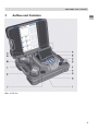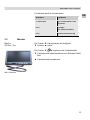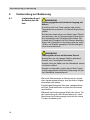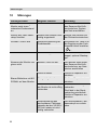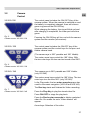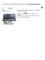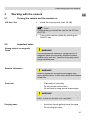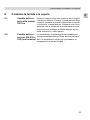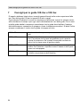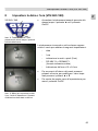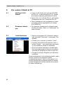
1
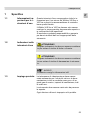
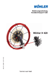
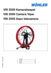
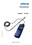
Bedienungsanleitung
Videoinspektion
Operating manual
EN
Service Camera
Istruzioni d‘uso
Videoispezione IT
Best.- Nr. 22357 2010-05-18
Wöhler VIS 2xx
Wöhler VIS 3xx
Technik nach Maß
Inhalt
Inhalt
1
Allgemeines...........................................4
1.1
1.2
1.3
1.4
1.5
1.6
1.7
Informationen zur Bedienungsanleitung ........ 4
Hinweise in der Bedienungsanleitung ........... 4
Bestimmungsgemäße Verwendung .............. 4
Lieferumfang ................................................. 5
Transport....................................................... 5
Entsorgung .................................................... 6
Herstelleranschrift ......................................... 7
2
Technische Daten .................................7
2.1
2.2
2.3
2.4
2.5
2.6
Monitor .......................................................... 7
Miniatur- Kamerakopf Farbe.......................... 7
Dreh-/ Schwenkkamerakopf .......................... 8
Schubstange ................................................. 8
Digitale Meterzählung (VIS 230/240/340)..... 8
Speichermöglichkeit (VIS 240 / VIS 340) ..... 8
3
Aufbau und Funktion............................9
3.1
Ausführungen .............................................. 11
3.1.1 VIS 2xx........................................................ 11
3.1.2 VIS 3xx........................................................ 11
3.2
3.3
4
Vorbereitung zur Bedienung .............14
4.1
Ladezustand und Aufladen der Akkus......... 14
5
Bedienung ...........................................15
5.1
5.2
Einschalten von System und Monitor .......... 15
Hinweise zur Bedienung.............................. 15
6
Austausch von Kamerakopf und
Kuppel ..................................................17
6.1
Wechsel der Kuppel des Farbkamera-kopfes
VIS 3xx........................................................ 17
Austausch des Kamerakopfes bei der VIS
230 / 330 (mit Lokator) ................................ 17
6.2
2
Bedienfeld ................................................... 12
Monitor ........................................................ 13
Inhalt
7
Einstellen von Datum und Uhrzeit
(VIS 240 /340)....................................... 18
8
Abspielen von Videos am PC ............ 19
8.1
8.2
8.3
Installation des VLC-Viewer........................ 19
Standbilder erzeugen................................... 19
Ausgabeverzeichnis für Standbilder ............ 20
9
Empfehlungen zu Führungshilfen
VIS 2xx / VIS 3xx ................................. 21
10
Störungen............................................ 22
11
Wartung ............................................... 23
12
Garantie und Service.......................... 24
12.1
12.2
Garantie ....................................................... 24
Service......................................................... 24
13
Zubehör ............................................... 25
14
Konformitätserklärung....................... 26
3
DE
0BAllgemeines
1
Allgemeines
Diese Bedienungsanleitung ermöglicht Ihnen die
sichere Bedienung der Wöhler VIS 2xx und
VIS 3xx. Bewahren Sie diese Bedienungsanleitung dauerhaft auf.
Wöhler VIS 2xx und VIS 3xx dürfen grundsätzlich
nur von fachkundigem Personal für den bestimmungsgemäßen Gebrauch eingesetzt werden.
Für Schäden, die aufgrund der Nichtbeachtung
dieser Bedienungsanleitung entstehen, übernehmen wir keine Haftung.
1.1
Informationen zur
Bedienungsanleitung
1.2
Hinweise in der
WARNUNG!
BedienungsanleiKennzeichnet Hinweise, bei deren Nichtbeachtung
tung die Gefahr der Verletzung oder des Todes
besteht.
ACHTUNG!
Kennzeichnet Hinweise auf Gefahren, die Beschädigungen des Geräts zur Folge haben können.
HINWEIS!
Hebt Tipps und andere nützliche Informationen
hervor.
1.3
4
Bestimmungsgemäße Verwendung
Die Videoinspektionskamera darf ausschließlich
zur optischen Kontrolle und Dokumentation in
Rohren und Schächten, z.B. Abgasanlagen, Lüftungsanlagen, Abwasserrohren etc., eingesetzt
werden.
Die Anwendung des Geräts darf nur durch fachkundiges Personal erfolgen.
Jede weitere Verwendung gilt als nicht bestimmungsgemäß und ist untersagt.
0BAllgemeines
1.4
Lieferumfang
Gerät
Lieferumfang
VIS 2xx / 3xx
Koffer
DE
Schubstange
Monitor
2 Wechselakkus
NiMH
1 Antirutsch- Matte
Netzgerät
2 GB SD-Karte
(VIS 240 / VIS 340)
Mini USB-Kabel
(VIS 240 / VIS 340)
VIS 2xx
MiniaturFarbkamerakopf
VIS 3xx
Dreh-/ schwenkbarer
Farbkamerakopf
5 Ersatzkunststoffkuppeln
1.5
Transport
ACHTUNG!
Durch unsachgemäßen Transport kann das Gerät
beschädigt werden!
Um Transportschäden zu vermeiden, muss das
Gerät stets in dem dafür vorgesehenen Koffer
transportiert werden.
Der Koffer wird mit dem Gerät im Set erworben.
5
0BAllgemeines
1.6
Entsorgung
Elektronische Geräte dürfen nicht im Hausmüll
entsorgt werden, sondern müssen gemäß den
geltenden Umweltvorschriften entsorgt werden.
Schadhafte Akkus gelten als Sondermüll und
müssen zur Entsorgung in den vorgesehenen
Sammelstellen abgegeben werden.
6
1BTechnische Daten
1.7
2
Herstelleranschrift
DE
Technische Daten
2.1
Monitor
Abb. 1: Monitor
2.2
Wöhler Messgeräte Kehrgeräte GmbH
Schützenstr. 41
33181 Bad Wünnenberg
Tel.: +49 2953 73-100
Fax: +49 2953 73-250
E-Mail: [email protected]
Service-Hotline:
+49 2953 73-200
Miniatur- Kamerakopf Farbe
Abb. 2: Miniatur-Kamerakopf
Beschreibung
Angabe
TFT - Display
7“ / 16:9
Gewicht
400 g
Maße Gehäuse
176 x 114 x 32 mm
Videoausgang
FBAS-Signal
Stromversorgung
1 x Akku NiMH
Stromaufnahme
Netzteil
Spannung
12 V
Beschreibung
Angabe
Typ
1/3“ Color CCD
Lichtempfindlichkeit
0,5 Lux
Objektiv
f = 2,31 mm, F = 2,4
Bilderfassungswinkel
120°
Lichtquellen
12 weiße LEDs
Schutz
Wasserdicht nach
IP 68
Maße
26 mm x 38 mm
7
1BTechnische Daten
2.3
Dreh-/
Schwenkkamerakopf
Beschreibung
Angabe
Typ
1/3“ Color CCD
Lichtempfindlichkeit
0,5 Lux
Objektiv
f = 2,31 mm, F = 2,4
Bilderfassungswinkel
120°
Lichtquellen
12 weiße LEDs
Schutz
wasserdicht nach IP
67
Abb. 3:
Dreh-/Schwenkkamerakopf
Maße
40 mm x 60 mm
2.4
Beschreibung
Angabe
Länge
20 m
Optional auch mit
30 m erhältlich
Durchmesser
6,5 mm (VIS 3xx)
6 mm (VIS 2xx)
2.5
Schubstange
Digitale Meterzäh- Beschreibung
lung
(VIS 230/240/340) Auflösung
Max. Abweichung
2.6
8
Speichermöglich- Beschreibung
keit
(VIS 240 / VIS 340) Speicherkarte
Angabe
0,04 m
10% vom Messwert
Angabe
max. 32 GB (Karte
muss mit dem PC
entsprechend formatiert werden FAT 32)
Aufnahmekapazität
ca. 1h / GB
Auflösung der Aufnahme
640 x 480 (VGA)/
max. 30 fps
Aufnahmeformat
ASF (MPEG4)
2BAufbau und Funktion
3
Aufbau und Funktion
DE
Abb. 4: VIS 3xx
9
2BAufbau und Funktion
Legende:
F
Monitor
Bedienungstasten Monitor
- Helligkeit / Kontrast
- Farbregler
Bedienungstasten und Kamerasteuerung (nur bei VIS 3xx)
mit Aufnahme- und Playfunktion (VIS 240 / VIS 340)
Kamerakopf, wasserdicht:
VIS 3xx: dreh- und schwenkbarer
Farbkamerakopf 40 mm Ø
VIS 2xx: Miniatur- Farbkamerakopf 26 mm Ø
Systemschalter mit folgenden Funktionen:
- Ein-/ Aus (System)
- Geräte- und Akkuzustandsanzeige
- Reset Meterzählung
- Escape
Kartenslot für Speicherkarte (VIS 240 / VIS 340)
G
H
I
J
K
L
M
N
O
Mini-USB-Anschluss (VIS 240 / VIS 340)
Netzteilanschluss (18V/1,6A)
Video-Ausgang
Ablagefach 1 für Zubehör
Reserveakku
Netzteil
Aktiver Akku
Ablagefach 2 für Zubehör
Ablagefach 3 für Zubehör
A
B
C
D
E
10
2BAufbau und Funktion
3.1
DE
Ausführungen
Die Ausführungen unterscheiden sich wie folgt:
3.1.1
VIS 2xx
Ausstattung
-
Anwendungsbereich
3.1.2
-
Miniaturkamerakopf: 26 mm Ø
VIS 220: Metrierung auf der GFKSchubstange
VIS 230: elektronische Meterzählung, optional auch mit Lokator Wöhler L 24
VIS 240: zusätzlich mit Speichermöglichkeit
für Videoaufnahmen
Abgasleitungen
Lüftungsanlagen
Schadstellenanalyse in Abwasserrohren
bei dem Lokator L 24, erst ab 50 mm Ø
VIS 3xx
Ausstattung
-
-
Anwendungsbereich
-
-
Dreh- und schwenkbarer Kamerakopf
(Optik drehbar um 360° und schwenkbar
um 180° ) mit 40 mm Ø
VIS 330: elektronische Meterzählung, optional auch mit Lokator Wöhler L 24
VIS 340: zusätzlich mit Speichermöglichkeit
für Videoaufnahmen
Abgasleitungen, aber nicht in Abgasleitungen mit weniger als 50 mm Ø und einem
87°Bogen verwenden
Schornsteine
Lüftungsanlagen
Schadstellenanalyse in Abwasserrohren ab
70 mm Ø
11
2BAufbau und Funktion
3.2
Bedienfeld
VIS 220 /230
Auf dem Bedienfeld befindet sich der Ein- und Ausschalter für das Kamerasystem. Bei eingeschalteter
Kamera und vollständig geladenem Akku ist der Einschaltknopf grün umleuchtet.
Während des Aufladens des Akkus blinkt die Umrandung rot und nach dem Aufladen leuchtet der untere
Teil rot.
Abb. 5:
Bedienfeld der VIS 220 / 230
Der Ein- und Ausschalter schaltet sowohl die Kamera
als auch den Monitor an. (Gilt für alle Versionen)
VIS 320 / 330
Auf dem Bedienfeld befinden sich der Ein- und Ausschalter für das Kamerasystem sowie die Bedienknöpfe für den dreh- und schwenkbaren Kamerakopf.
Die Optik ist um 360° drehbar und um 180° schwenkbar.
Abb. 6:
Bedienfeld der VIS 320 / 330
VIS 240 / 340
Abb. 7:
Bedienfeld VIS 240 / 340
12
Über die mittleren Pfeiltasten lässt sich das Schwenken um 180° steuern. Mit den beiden äußeren Drehpfeiltaste lässt sich die Linse insgesamt um 360°
drehen.
Nur bei der VIS 340 ist die Optik um 360° drehbar
und um 180° schwenkbar. Über die mittleren Pfeiltasten lässt sich das Schwenken um 180° steuern.
Mit den beiden äußeren Drehpfeiltaste lässt sich die
Linse insgesamt um 360° drehen (nicht VIS 240).
Äußeren Drehpfeiltasten: Im Abspielmodus Navigieren im Menü
(VIS 240 / VIS 340).
Rec-Taste: Videoaufnahme starten und beenden.
Play-Taste: Abspielen eines aufgezeichneten Videos
Ein-/Ausschalter: Wiedergabe stoppen
REC-Taste 2 Sekunden gedrückt halten: Löschen
einer Videodatei. Es erscheint ein Fenster mit der
Anzeige „Video gelöscht“.
Pfeiltasten: Auswahl der abzuspielenden Aufnahme.
2BAufbau und Funktion
Funktionen des Ein-/Ausschalters
3.3
Monitor
VIS 2xx / 3xx
Drücken
Funktion
2 Sekunden
Ein-/Ausschalten des
Systems
kurz
Escape
(im Abspielmodus)
kurz
Reset Meterzählung
DE
Monitor
Die Tasten ▼☼▲ regulieren die Helligkeit
▼: dunkler ▲: heller
Die Tasten ▼
▲ regulieren die Farbintensität
▼: Farbintensität abnehmend bis zum Schwarz/ Weiß
Bild
▲: Farbintensität zunehmend
Abb. 8: Monitor
13
3BVorbereitung zur Bedienung
4
4.1
Vorbereitung zur Bedienung
Ladezustand und
Aufladen der Akkus
WARNUNG!
Verletzungsgefahr bei falschem Umgang mit
Akkus!
Die Akkus nicht ins Feuer werfen oder hohen
Temperaturen aussetzen. Es besteht Explosionsgefahr!
Bei falscher Anwendung von Akkus kann Flüssigkeit austreten, die zu Hautreizungen führen kann.
Den Kontakt mit der Flüssigkeit vermeiden. Bei
Kontakt die Flüssigkeit mit viel Wasser abspülen.
Wenn die Flüssigkeit in die Augen gelangt, sofort
10 Min. mit Wasser ausspülen und unverzüglich
einen Arzt aufsuchen!
WARNUNG!
Lebensgefahr durch elektrischen Strom!
Netzstecker nie mit nassen Händen anfassen!
Netzteil von Feuchtigkeit fernhalten!
Netzteil nicht am Kabel aus der Steckdose ziehen,
es könnte reißen!
Netzteil nur betreiben, wenn die auf dem Typenschild angegebene elektrische Spannung mit der
der Steckdose übereinstimmt!
Wenn die Akkuanzeige im Monitor einen schwachen Ladezustand anzeigt, sind die Akkus folgendermaßen aufzuladen:
Zugehöriges Netzgerät über den Ladeanschluss
mit dem Gerät verbinden und an das Stromnetz
anschließen.
Während des Ladevorgangs blinkt der untere Teil
der Umrandung des Ein-/Ausschalters rot, nach
Abschluss des Ladevorgangs leuchtet der untere
Teil der Umrandung rot.
14
4BBedienung
5
Bedienung
5.1
DE
Einschalten von System und Monitor
•
VIS 2xx / 3xx
Einlegen der Speicherkarte (max. 32 GB)
HINWEIS!
Die Karte muss vorher mit dem PC formatiert werden (FAT 32).
•
5.2
Einschalten des Gerätes mit dem Ein-/ Ausschaltknopf auf dem Bedienfeld
Hinweise zur Bedienung
Starke magnetische oder elektrische Felder
ACHTUNG!
Die Kamera nicht in der Nähe von Fernsehtürmen,
mobilen Funkgeräten und anderen Quellen von
magnetischen oder elektrischen Feldern verwenden, da dies Bildstörungen zur Folge haben kann
Äußere Einflüsse
ACHTUNG!
Äußere Einflüsse wie statische Entladungen können Funktionsstörungen verursachen. In diesem
Fall sollte die Kamera aus- und anschließend wieder eingeschaltet werden.
15
4BBedienung
Schubstange
-
gleichmäßig, nicht ruckartig und ohne
Gewalt langsam ziehen und schieben
nicht über das Stangenende hinausziehen
nicht knicken oder über scharfe Kanten
ziehen
ACHTUNG!
Vor dem Einschieben die Schubstange mit einem
Tuch trocken wischen, damit keine Schmutz- /
Rußpartikel in den Haspelkorb ins Innere des Koffers gelangen können!
Koffer
-
Kofferinhalt vor Wasser schützen
Koffer nicht werfen
Kamerakopf
-
die Linse des Kamerakopfes vor Verkratzen schützen
HINWEIS!
Im Auslieferungszustand ist der Kamerakopf der
VIS 3xx mit einer Kunststoffkuppel geschützt, die
bei Bedarf, z.B. bei Kratzspuren, ersetzt werden
kann. Alternativ gibt es eine Glaskugel, die dort
aufgeschraubt werden kann!
16
5BAustausch von Kamerakopf und Kuppel
6
6.1
Austausch von Kamerakopf und Kuppel
Wechsel der Kuppel des
Farbkamerakopfes VIS 3xx
DE
Vor dem Einsetzen der neuen Kuppel muss das
Gewinde mit Silikon eingeschmiert werden. Bei
dem Austausch der Kuppel ist zu beachten, dass
die Kuppel bis zum letzten Gewindegang festgedreht sein muss. Ansonsten ist nicht gewährleistet, dass der Kamerakopf dicht ist, und es kann
durch Eindringen von Wasser und Schmutz zu
Funktionsstörungen kommen.
Abb. 9: Installieren der Kamerakuppel
6.2
Austausch des
Kamerakopfes
bei der VIS 230 /
330 (mit Lokator)
Der Miniatur- bzw. dreh-/ schwenkbare Kamerakopf kann durch ein Gewinde am Ende der
Schubstange auf -und abgeschraubt werden.
Erst eine feste Verschraubung sorgt für eine wasserdichte Verbindung.
ACHTUNG!
Der Kamerakopf soll mit der Hand fest verschraubt werden, keinesfalls mit einer Zange!
Abb. 10: Kamerakopf mit Lokator
17
6BEinstellen von Datum und Uhrzeit (VIS 240 /340)
7
Einstellen von Datum und Uhrzeit (VIS 240 /340)
VIS 240 / 340
•
Bei ausgeschalteter Kamera die Taste ▲ gedrückt halten und dabei die Kamera einschalten.
Abb. 11: Bedienfeld VIS 240 / 340:
Mit Pfeil markierte Tasten gleichzeitig drücken
Die Kamera schaltet sich ein und im Display erscheint
ein Menü, in dem folgende Einstellungen vorgenommen werden können:
Abb. 12: Menü zum Einstellen von
Datum, Zeit, Entfernungseinheit und
Format für die Datums- und Zeitangabe
18
-
Datum
-
Uhrzeit
-
Angabe in Metern oder Fuß (Feet)
-
DD.MM.YY oder DD/MM/YY
(Format der Datumsanzeige)
-
12 h oder 24 h Zeitanzeige
•
Sie bewegen sich im Menü mit den Pfeiltasten
und verändern einen Wert mit den Auf- und Abtasten.
•
Zum Verlassen des Menüs drücken Sie die An/Austaste
7BAbspielen von Videos am PC
8
8.1
Abspielen von Videos am PC
Installation des
VLC-Viewer
DE
• Legen Sie die mitgelieferte CD in das CDLaufwerk vom PC ein. (Der VLC-Viewer ist
auch im Internet kostenlos herunterzuladen.)
• Klicken Sie auf „vlc-1.0.2-win32.exe“, um den
VLC-Viewer auf Ihrem PC zu installieren.
• Nach erfolgter Installation können die Videoaufnahmen im AFS(MPEG 4)-Format direkt
wiedergegeben werden.
8.2
Standbilder erzeugen
• Um Standbilder von einem Video zu erzeugen, klicken Sie im Menü während des Abspielens auf Video – Schnappschuss.
Abb. 13: Standbilder erzeugen
19
8.3
Ausgabeverzeichnis für
Standbilder
• Klicken Sie nach dem Start des VLC-Viewers
auf "Extras" und anschließend auf "Einstellungen".
• Wählen Sie links das Symbol "Video".
• Klicken Sie im Feld "Videoschnappschüsse"
auf den Button "Durchsuchen..." und wählen
Sie einen Ordner aus, in dem Standbilder
gespeichert werden sollen.
• Sie können hier das Ausgabeformat der erzeugten Dateien auswählen (png oder jpg)
sowie ein eigenes Präfix angeben, das dem
Dateinamen vorangestellt wird.
• Mit dem Button "Speichern" werden die Einstellungen übernommen.
Da es sich bei dem Programm um kostenlose
Software ("Open Source") handelt, können wir
keinen technischen Support leisten. Weitere Informationen zu dem Programm sowie die aktuellste Version finden Sie auf der Webseite des Herstellers unter www.videolan.org
20
8BEmpfehlungen zu Führungshilfen VIS 2xx / VIS 3xx
9
Empfehlungen zu Führungshilfen VIS 2xx / VIS 3xx
DE
Im Folgenden sollen einige allgemeine Empfehlungen zum Einsatz von Führungshilfen
bei der Inspektion von Rohren und Schächten gegeben werden, die wir aus unserer
bisherigen Erfahrung gewonnen haben.
Da jedes Rohr- und Schachtsystem individuell verschieden ist, muss in jedem Einzelfall
vor Ort über die Benutzung der Hilfen entschieden werden. Bei der Auswahl der geeigneten Führungshilfe ist zu beachten, dass diese neben einer guten Führung ein problemloses Hineinschieben wie Hinausziehen des Kamerakopfes gewährleisten muss.
Die Gefahr eines möglichen Verklemmens oder Verhakens der Führungshilfe im Rohr
ist zu berücksichtigen.
Ø 40 - 50 mm
Das Videoinspektionssystem kann ohne Zubehör genutzt
werden
Ø 50 – 70 mm
Das Videoinspektionssystem kann ohne Zubehör genutzt
werden. Gegen das Zerkratzen der Linse kann der Objektivschutz verwendet werden. Wenn Wasser und Schlick im
waagerechten Teil vorhanden sind, verwenden Sie die
Rollenführung
Ø 70 – 100 mm
Die Inspektion ist problemlos mit und ohne Rollenführung
möglich. Für Fallrohre oder für die vertikale Inspektion ist
ein Führungsgewicht zu nutzen
Ø 100 – 154 mm
Es kann eine Zentrierhilfe, mit oder ohne eine Rollenführung mit Objektivschutz genutzt werden
21
9BStörungen
10
Störungen
Störungshinweis
Mögliche Ursache
Behebung
Batteriestandsanzeige im
Monitor zeigt einen
schwachen Ladezustand
an.
Akkus sind leer.
Den aktiven Akku gegen
den Reserve-Akku auswechseln bzw. System
ans Netz anschließen
Monitor aus, aber Kamerakopf leuchtet.
Stecker vom Monitor nicht
richtig eingesteckt.
Stecker vom Monitor auf
der Rückseite einstecken.
Schwarz / Weiß- Bild
Minimale Einstellung der
Farbintensität
Am Monitor die Taste 4 für
die Regulierung der Farbintensität höher einstellen
▲:
VIS 3xx: schlechte Sicht
Kunststoffkuppel verkratzt.
Austausch der Kunststoffkuppel, optional Glaskuppel.
Kamera oder Monitor reagieren nicht
Batterie / Akku ist leer.
Den aktiven Akku gegen
den Reserve-Akku auswechseln bzw. am Netzstecker anschließen
Gerät ist defekt.
Gerät zur Reparatur einschicken.
Stange ist gebrochen.
Gerät zur Reparatur einschicken.
Kabel-Steckverbindung
am Monitor ist nicht richtig
verbunden.
Die Steckverbindung neu
verbinden.
Die Kabel in der Steckverbindung sind defekt.
Gerät zur Reparatur einschicken.
Steckverbindung des
wechselbaren Farbkamerakopfes bei der VIS 230 /
330 mit Lokator ist nicht
richtig verbunden
Den wechselbaren Farbkamerakopf neu aufstecken .
Blauer Bildschirm mit NO
SIGNAL auf dem Monitor
22
10BWartung
11
Wartung
DE
Hinweise zu Wartung und Pflege
Um das einwandfreie Funktionieren der VIS 2xx /
3xx gewährleisten zu können, muss das Gerät
regelmäßiger Wartung unterzogen werden. Die
Wartung umfasst Tätigkeiten, die von dem Bediener selbst ausgeführt werden können.
Kamerakopf
Reinigen Sie das Objektiv nur mit einem sauberen, weichen und feuchten Tuch ohne Einsatz von
Reinigungsmitteln.
Schubstange
Regelmäßig die Schubstange komplett aus dem
Koffer ziehen und dann mit einem weichen feuchten Tuch säubern.
Monitor
Reinigen Sie den Monitor mit einem weichen Tuch.
23
11BGarantie und Service
12
12.1
Garantie und Service
Garantie
Jedes Videoinspektionssystem Wöhler VIS 2xx /
3xx wird im Werk in allen Funktionen geprüft und
verlässt unser Werk erst nach einer ausführlichen
Qualitätskontrolle.
Bei sachgemäßem Gebrauch beträgt die Garantiezeit bei den Wöhler VIS 2xx / 3xx zwölf Monate
ab Verkaufsdatum, ausgenommen sind alle Akkus
und die Kunststoffkuppel der VIS 3xx.
Die Kosten für den Transport und die Verpackung
des Geräts im Reparaturfall werden von dieser
Garantie nicht abgedeckt.
Diese Garantie erlischt, wenn Reparaturen und
Abänderungen von dritter, nicht autorisierter Stelle
an dem Gerät vorgenommen wurden.
12.2
24
Service
Der SERVICE wird bei uns sehr groß geschrieben. Deshalb sind wir auch selbstverständlich
nach der Garantiezeit für Sie da.
•
Sie schicken die Viedeoinspektionskamera zu
uns, wir reparieren es innerhalb weniger Tage
und schicken es Ihnen mit unserem Paketdienst zurück.
•
Sofortige Hilfe erhalten Sie durch unsere
Techniker am Telefon.
12BZubehör
13
Zubehör
DE
Wöhler VIS Führungshilfeset 110 für die VIS 3xx
Best.-Nr. 3884 J
Wöhler VIS Führungshilfeset 70 für die VIS 2xx
Best.-Nr. 3883 J
Erweiterungselement Wöhler VIS Führungssystem
Best.-Nr. 3853 J
Stangenelement Wöhler VIS Führungssystem
Best.-Nr. 3854 J
Wöhler Rollenführung für die VIS 3xx
Best.-Nr. 3681 J
Verlängerungsstück Wöhler VIS Führungssystem
Best.-Nr. 21736 J
Führungsgewicht Edelstahl
Best.-Nr. 3857 J
Stabilisierungskugel
Best.-Nr. 3634 J
Schnellladegerät 2,5 A / 230 V / 50 HZ
Best.-Nr. 56102 J
Ersatzwechselakku NiMH
Best.-Nr. 3715 J
Kuppelschutz für VIS 3xx
Best.-Nr. 3682 J
Glaskuppel
Best.-Nr. 3674 J
Ersatzkunststoffkuppeln (10 Stück)
Best.-Nr. 3675 J
Antirutschmatte
Best.-Nr. 56037 L
Zusatzbeleuchtung mit weißen LEDs für die VIS 220
Best.-Nr. 9377 P
Seitsichtspiegel Minikamerakopf Wöhler VIS 2xx
Best.-Nr. 7923 J
Bürstenset Wöhler VIS (24teilig)
Best.-Nr. 3858 J
Schubhülse für VIS 2xx
Best.-Nr. 3827 J
Schubhülse und Objektivschutz für VIS 2xx
Best.-Nr. 3847 J
25
13BKonformitätserklärung
14
Konformitätserklärung
Der Hersteller:
WÖHLER Messgeräte Kehrgeräte GmbH
Schützenstr. 41, D-33181 Bad Wünnenberg
erklärt, dass die Produkte:
Produktname: Videoinspektionssystem
Modellnummer: Wöhler VIS 2xx / 3xx
den wesentlichen Schutzanforderungen entsprechen, die in den Richtlinien des Rates
zur Angleichung der Rechtsvorschriften der Mitgliedsstaaten über die elektromagnetische Verträglichkeit (2004/108/EG) und über die Niederspannung (2006/95/EG) festgelegt sind.
Zur Beurteilung des Produkts hinsichtlich der elektromagnetischen Verträglichkeit wurden folgende Normen herangezogen:
EN 55024
EN 55022 Klasse B
26
Contents
Contents
EN
1
General Information ........................... 29
1.1
1.2
1.3
1.4
1.5
1.6
1.7
Operation Manual Information ..................... 29
Notes ........................................................... 29
Intended Use ............................................... 29
Components ................................................ 30
Transport ..................................................... 30
Information on disposal................................ 31
Manufacturer................................................ 32
2
Specifications ..................................... 32
2.1
2.2
2.3
2.4
2.5
Monitor......................................................... 32
Color Camera Head..................................... 32
Camera head, pan and tiltable..................... 33
Rod .............................................................. 33
Storage (VIS 240 / VIS 340) ....................... 33
3
Component explanation..................... 34
3.1
Versions....................................................... 36
3.1.1 VIS 2xx ........................................................ 36
3.1.2 VIS 3xx ........................................................ 36
3.2
3.3
Camera Control ........................................... 37
Monitor......................................................... 39
4
Getting started .................................... 40
4.1
Check battery status .................................... 40
5
Working with the camera ................... 41
5.1
5.2
Turning the camera and the monitor on....... 41
Important notes............................................ 41
6
Changing the camera head and the
dome..................................................... 42
6.1
Changing the dome of the colour camera head
VIS 3xx ........................................................ 42
Exchanging the camera head VIS 230 / 330
(with locator) ................................................ 42
6.2
7
Setting Date and Time (VIS 240 /340)43
8
Play videos at PC................................ 44
27
Contents
28
8.1
8.2
8.3
Installation VLC-Viewer ............................... 44
Create frames.............................................. 44
Snapshotlist................................................. 44
9
Guide conducts VIS 2xx / VIS 3xx .....45
10
Troubleshooting..................................46
11
Maintenance ........................................47
12
Warranty and service .........................48
12.1
12.2
Warranty...................................................... 48
Service ........................................................ 48
13
Accessories.........................................49
14
Declaration of conformity EC ............50
14BGeneral Information
1
General Information
1.1
Operation Manual Information
1.2
Notes
EN
This operation manual allows you to safely work
with the Wöhler VIS 2xx / 3xx service camera.
Please keep this manual for your information.
The Wöhler VIS 2xx / 3xx service camera should
be used by trained professionals for its intended
use only.
Liability is void for any damages caused by not
following this manual.
WARNING!
Not following this warning can cause injury or
death.
ATTENTION!
Not following this note can cause permanent
damage to the analyzer.
NOTE!
Usefull information
1.3
Intended Use
Do not use the Wöhler VIS 3xx / 2xx for any other
use than set out in this manual.
Use the Wöhler VIS 3xx / VIS 2xx Service Camera for the inspection of pipeworks, drains and
sinks, such as exhaust systems, ductworks etc.
and for the documentation of damages.
29
14BGeneral Information
1.4
Components
Model
Components
VIS 2xx / 3xx
Heavy duty carrying
case
Push rod
Monitor
2 Replacement batteries NiMH
1 Anti slide mat
Power supply
2 GB CF-Card
(VIS 240 / VIS 340)
Mini USB-cable
(VIS 240 / VIS 340)
VIS 2xx
Color camera head
VIS 3xx
Pan & tilt color camera head
5 Replacement glass
domes, extra
1.5
Transport
ATTENTION!
The camera should be transported in the original
carrying case only!
30
14BGeneral Information
1.6
EN
Information on disposal
Electronic equipment does not belong into domestic waste, but must be disposed in accordance
with the applicable statutory provisions.
You may hand in any defective batteries taken out
of the unit to our company as well as to recycling
places of public disposal systems or to selling
points of new batteries or storage batteries.
31
15BSpecifications
1.7
2
Manufacturer
Specifications
2.1
Monitor
Fig. 1: Monitor
2.2
Color Camera
Head
Fig. 2: Miniature camera head color
32
Wöhler Messgeräte Kehrgeräte GmbH
Schützenstr. 41
33181 Bad Wünnenberg
Tel.: +49 2953 73-100
Fax: +49 2953 73-250
E-Mail: [email protected]
Service-Hotline:
+49 2953 73-200
Description
Date
TFT - Display
7“ / 16:9
Weight
400 g
Casing size
176 x 114 x 32 mm
Video out
FBAS
Power Supply
1 x rechargeable battery NiMh
Power
Power supply unit
Voltage
12 V
Description
Date
Type
1/3“ Color CCD
Sensitivity
0.5 Lux
Lens system
f = 2.31 mm, F = 2.4
Field of view
120°
Light source
12 white LEDs
Protection
Waterproof acc. to
IP 68
Size
26 mm x 38 mm
15BSpecifications
2.3
Camera head, pan Description
and tiltable
Date
Typ
1/3“ Color CCD
Sensitivity
0.5 Lux
Lens system
f = 2.31 mm, F = 2.4
Field of view
120°
Light source
12 white LEDs
Protection
Waterproof acc. to
IP 67
Size
40 mm x 60 mm
Description
Date
Length
20 m
(Optional 30 m)
Diameter
6.5 mm (VIS 3xx)
6 mm (VIS 2xx)
Description
Date
Resolution
0.04 m
Max. discrepancy
10% of reading
EN
Fig. 3: Camera head, pan- and tiltable
2.4
2.5
2.6
Rod
Digital distance
measurement
(VIS 230/240/340)
Storage
Description
(VIS 240 / VIS 340)
Date
Memory card
max. 32 GB
(You must format the
card on the PC,
FAT 32.)
Capacity
App. 1h / GB
Resolution
640 x 480 (VGA)/
max. 30 fps
Format
ASF (MPEG4)
33
16BComponent explanation
3
Component explanation
Fig. 4: VIS 3xx
34
16BComponent explanation
Component explanation:
F
Monitor
Monitor controls
- Brightness / contrast
- Color
Camera control (only VIS 3xx)
with record and play-function (VIS 240 / VIS 340)
Camera head, waterproof:
VIS 3xx: pan- and tiltable
Color camera head 40 mm Ø
VIS 2xx: Miniature color camera head 26 mm Ø
Main power switch with the following functions:
- ON / OFF (System)
- Battery and system status
- Reset distance measurement (press shortly)
- Escape
Cardslot for memory card (VIS 240 / VIS 340)
G
H
I
J
K
L
M
N
O
Mini-USB-port (VIS 240 / VIS 340)
Power supply socket (18V/1,6A)
Video out
Accessory compartment 1
Rechargeable battery, extra
Power supply
Rechargeable battery, in use
Accessory compartment 2
Accessory compartment 3
A
B
C
D
E
EN
35
16BComponent explanation
3.1
Versions
Ther differences between the versions are as follows:
3.1.1
VIS 2xx
Equipment
Application area
-
3.1.2
VIS 3xx
Equipment
-
Application area
-
36
Miniature Camera head: 26 mm Ø
VIS 220: Metric marked push rod cable
VIS 230: digital meter counter (optional also
with Locator Wöhler LT 24
VIS 240: Video file memory
Flue gas lines
Air conditioning and heating lines
Analysis of defects in waste water pipes (40
mm Ø and bigger)
With the Lokator: 50 mm Ø and bigger
Camera head, pan- and tiltable
(360° panable and 180° tiltable camera eye)
40 mm Ø
VIS 330: digital meter counter (optional also
with Locator Wöhler LT 24)
VIS 340: Video file memory
Flue gas lines with a diameter greater than
50 mm Ø and bows of 87° and more.
Chinmeys
Exhaust systems
Detection of problems in waste pipes with
70 mm Ø or bigger
16BComponent explanation
3.2
Camera
Control
VIS 220 /230
EN
The control panel includes the ON-/OFF-Key of the
camera system. When the camera is switched on and
the battery is completely charged, there will shine a
green ring around the ON-Off-Key.
While charging the battery, the ring will blink red and
after charging is completed, the lower part will shine
green.
Fig. 5:
Camera control VIS 220 / 230
Pressing the ON-/Off-key will turn on both the camera
system and the monitor (all versions).
VIS 320 / 330
The control panel includes the ON-OFF key of the
camera system and the control keys for the pan- and
tiltable camera head.
(The camera eye is 360° panable and 180° tiltable).
The center arrow keys control the 180° tilting. With
the two outer keys the lens can be turned round 360°.
Fig. 6:
Camera control VIS 320 / 330
VIS 240 / 340
The camera eye is 360° panable and 180° tiltable.
(only VIS 340)
The center arrow keys control the 180° tilting. The two
outer keys turn the lens 360° (only VIS 240).
In the Play-mode, the two outer arrow keys are also
used for the menu navigation (VIS 240 and VIS 340).
Fig. 7:
Camera control VIS 240 / 340
The Rec-key starts and finishes the Video recording.
Press the Play-Key to play the stored video file.
Press ON-/OFF to stopp the play back.
Press the Rec-key two seconds to delete a selected
video file. On screen the note “Video deleted” will
appear.
Arrow keys: Selection of the video
37
16BComponent explanation
Functions of the ON-/OFF-key
38
Press
Functions
2 seconds
System ON/OFF
shortly
Escape (play mode)
shortly
Reset digital meter
counter
16BComponent explanation
3.3
EN
Monitor
Monitor
VIS 2xx / VIS 3xx
With the keys ▼☼▲ the brightness can be adjusted.
▼: darker ▲: brighter
▲ the color intensity can be
With the keys ▼
adjusted
▼: decreasing color intensity up to black and white
▲: increasing color intensity
Fig. 8: Monitor
39
17BGetting started
4
4.1
Getting started
Check battery
status
WARNING!
Incorrect use of batteries can cause injury!
Do not expose batteries to fire or high temperatures, that will cause danger of explosion!
Liquids can pore out of the batteries due to mistreatment. Never touch the liquid. If you got in
contact to the liquid remove it with water and see
your doctor as soon as possible.
WARNING!
Risk of electrical shock!
Never touch the recharger with wet hands!
Protect the recharger against water and moisture!
Do not unplug the recharger by pulling the cable!
Do not use the recharger when the voltage requirements of the recharger and the supply do not
match!
When the monitor indicates a low battery status,
charge the batteries as follows:
Before you plug the power supply unit into the
outlet, connect it with the camera system.
During the charging process the lower part of the
border around the ON-/Off-key will blink red. After
the charging process has finished it is highlighted
red.
40
18BWorking with the camera
5
Working with the camera
5.1
EN
Turning the camera and the monitor on
•
VIS 2xx / 3xx
Install the memory card (max. 32 GB)
Note!
It is necessary to format the card on the PC first
(FAT 32).
•
5.2
Turn on the camera system by pressing the
ON/OFF-key.
Important notes
Strong electric or magnetic
fields
WARNING!
Do not expose the camera to strong electric or
magnetic fields as caused by television towers,
mobile radio units etc., because they may cause
image interferences.
Exterior influences
WARNING!
Exterior influences as statical discharges may
cause dysfunctions. In this case switch the camera
off and on.
Push rod
-
Push and pull smoothly
Do not exceed rod end limit
Do not bend or drag across sharp edges
WARNING!
Dry and clean the rod with a cloth, before pulling it
back, so that no dirt and soot can enter!
Carrying case
-
Avoid any liquids getting inside the case.
Do not drop the case.
41
19BChanging the camera head and the dome
-
Camera head
Protect the lens of the camera head
against scratches.
NOTE!
Originally the camera head VIS 3xx is protected
by a plastic dome, which can be substituted by a
glass dome if necessary. Alternatively a glass
dome can be purchased that must be screwed
onto the camera head!
6
6.1
Changing the camera head and the dome
Changing the
dome of the colour camera head
VIS 3xx
Before installing the new dome, grease the screw
thread slightly with silicone. Take care that the
dome is screwed firmly up to the last thread. Otherwise the camera head will not be tight, and water and dust can get inside.
Fig. 9: Installing the dome
6.2
Exchanging the
camera head VIS
230 / 330 (with locator)
Fig. 10: Camera head with locator
42
The rod end has a screw thread, so that the miniature camera head and the pan- and tiltable camera head can be fixed and removed by screwing.
Take care to screw the rod and the camera head
firmly together, otherwise the assembly will not be
waterproof.
ATTENTION!
Only use your hands to screw the camera head,
but never a tong!
20BSetting Date and Time (VIS 240 /340)
7
Setting Date and Time (VIS 240 /340)
VIS 240 / 340
•
EN
With the camera switched off, press the ▲ button and the ON-/OFF-button simultaneously for
two seconds.
Fig. 11: Control panel VIS 240 / 340:
Press marked buttons simultaneously
The camera switches on and the display will show a
menu where the following setups can be done.
-
Date
-
Time
-
Distance in Meter or Feet
-
DD.MM.YY or DD/MM/YY
-
12 h or 24 h clock
•
Move from one parameter to the other with the
arrow keys and change the values with the
▲/▼-keys.
•
Press the ON-OFF-button to escape the menu.
Fig. 12: Setup Menu
43
21BPlay videos at PC
8
8.1
Play videos at PC
Installation VLCViewer
• Insert CD. (The VLC Viewer is available as
freeware in the internet.)
• Click on „vlc-1.0.2-win32.exe“ and install the
VLC-Viewer onto your PC.
• After the installation, the video files can be replayed in the AFS/MPEG4 format.
8.2
Create frames
• To create a single frame of a video, click on
video > snapshot while running the video.
8.3
Snapshotlist
• Click on Tools > Preferences for storing.
• The window shown on the left will open.
• Select the Icon Video.
• Click on “Browse” and select the path where
you want to store your snapshot. You can select the file format (png or jpg) and add your
own prefix to the filename.
• Click on “Save”.
As the programm is a freeware (“Open Source”)
Wöhler cannot provide any technical support. You
will find more information as well as the current
version on the Website of the softwaremanufactor
www.videolan.org
44
22BGuide conducts VIS 2xx / VIS 3xx
9
Guide conducts VIS 2xx / VIS 3xx
EN
This chapter contains some recommendations based on our experience about the selection of guide conducts for the inspection in tubes and ducts.
As all tubes and chimney systems are different, the user has to decide about the guide
conducts in every single case. For the selection of the correct tool it is important to
consider that the guide conduct has to facilitate the introduction and the extraction of
the camera head, as well as an adequate guidance. The danger of jamming or getting
stuck in the tube has to be avoided.
Ø 40 - 50 mm
Use the service camera without accessories.
Ø 50 – 70 mm
You can use the service camera without accessories. The
lens can be protected by the guidance sleeve. If there is
water and mud in the horizontal part, we recommend to use
the roller guide.
Ø 70 – 100 mm
The inspection is possible with the roller guide and without
it. Use the guidance weight for the vertical inspection or for
the inspection of downpipes.
Ø 100 – 154 mm
A centering brush can be used with the roller guide or without it and with the lens protection.
45
23BTroubleshooting
10
Troubleshooting
Problem
Possible reason
Solution
The battery level indicator
shown in the display indicates a low battery status.
Rechargeable batteries
are empty.
Replace or recharge batteries.
The monitor is off, but the
LEDs of the camera head
are shining.
The monitor is not connected correctly.
Plug in the monitor plug.
Monitor displays black and
white.
Minimal color intensity is
set.
Adjust the color intensity
of the monitor (see chapter 3.3)
▲:
VIS 3xx: Bad image
Plastic dome is scratched.
Change the plastic dome
(Option: Glass dome).
Camera or monitor do not
react.
Disposable or rechargeable batteries are empty.
Replace or recharge batteries.
The camera system is
damaged.
Send the device in for
repair.
The rod is broken.
Send the device in for
repair.
The monitor is not connected correctly.
Connect the monitor correctly.
The connection cable is
broken. Send the device
in for repair.
VIS 230 / 330: The color
camera head is not connected correctly to the
locator.
Attach the changeable
color camera head again.
The monitor display is
blue and the message NO
SIGNAL appears.
46
24BMaintenance
11
Maintenance
EN
Regular maintenance
Proper operation of the VIS 2xx / 3xx requires
regular maintenance. The following maintenance
works can be done by the user himself.
Camera head
Only use soft, damp cloth to clean the lens. Never
use any cleanser.
Push rod
Regularly pull the rod out of the case and clean it
with a soft, damp cloth.
Monitor
Use soft, dry cloth to clean the monitor.
47
25BWarranty and service
12
Warranty and service
12.1
Warranty
Each Wöhler VIS 2xx / 3xx will be tested in all
functions and will leave our factory only after extensive quality control testing.
If used properly, the warranty period for the VIS
2xx / 3xx will be 12 month from the date of sale.
Not covered by the warranty are the batteries and
the plastic dome VIS 3xx.
Service by non authorized personnel or making
modifications on the service camera voids any
warranty.
12.2
Service
Wöhler has built our reputation on excellence in
customer service. Therefore, of course, we are
readily available to assist you after the guarantee
period ends.
48
•
Send us the device, and we will repair it and
return it to you with our package service.
•
Immediate help is provided by our technical
staff over the telephone.
26BAccessories
13
Accessories
EN
Wöhler VIS Guidance Set 110 for VIS 3xx
Order No. 3884 J
Wöhler VIS Guidance Set 70 for VIS 2xx
Order No. 3883 J
Wöhler VIS Centering Brush Extension
Order No. 3853 J
Wöhler VIS Centering Brush
Order No. 3854 J
Camera Roller Guide VIS 3xx
Order No. 3681 J
Wöhler VIS Stabilisation Tube
Order No. 21736 J
Guidance Weight, stainless steel
Order No. 3857 J
Guidance Ball
Order No. 3634 J
Wöhler Quick Charger 2,5 A / 230 V / 50 HZ
Order No. 56102 J
Spare Battery NiMh tested
Order No. 3715 J
Protection Sleeve for Wöhler VIS 3xx
Order No. 3682 J
Glass Dome
Order No. 3674 J
Replacement Plastic Domes (10 pcs.)
Order No. 3675 J
Anti Slide Mat
Order No. 56037 L
Wöhler Supplementary Light Ring with white LEDs
Order No. 9377 P
Wöhler Side View Mirror for the VIS 2xx
Order No. 7923 J
Pocket Multimediarecorder with AV- IN
Order No. 3726 L
Wöhler VIS Centering System (24 pcs.)
Order No. 3858 J
Guidance Sleeve for VIS 2xx
Order No. 3827 J
Guidance Sleeve with Protection Cage for VIS 2xx
Order No. 3847 J
49
27BDeclaration of conformity EC
14
Declaration of conformity EC
WÖHLER Messgeräte Kehrgeräte GmbH
Schützenstr. 41, D-33181 Bad Wünnenberg
Declares that the following product:
Name: Wöhler Service Camera
Model: Wöhler VIS 2xx / 3xx
Complies with the safety requirements set out in the directives of the European parliament and council on the approximation of laws of the Member States relating to electromagnetic compatibility (204/108/EC) and low voltage (2006/95/EC).
The following standards were used to access the products in terms of electromagnetic
compatibility.
EN 55024
EN 55022 Class B
50
Indice
Indice
IT
1
Specifica .............................................. 53
1.1
1.2
1.3
1.4
1.5
1.6
1.7
Informazioni importanti per le istruzioni d‘uso ..
.................................................................... 53
Indicazioni nelle istruzioni d‘uso................... 53
Impiego previsto .......................................... 53
Fornitura ...................................................... 54
Trasporto ..................................................... 54
Smalitmento................................................. 54
Indirizzo venditore........................................ 55
2
Dati tecnici........................................... 55
2.1
2.2
2.3
2.4
2.5
Monitor......................................................... 55
Minitestata a colori....................................... 55
Testata girevole 360°x180°.......................... 56
Metratura digitale (VIS 230/240/340) .......... 56
Cavo semirigido ........................................... 56
3
Struttura e funzione............................ 57
3.1
Versioni........................................................ 59
3.1.1 VIS 2xx ........................................................ 59
3.1.2 VIS 3xx ........................................................ 59
3.2
3.3
Tastiera di comando .................................... 60
Monitor......................................................... 60
4
Preparazioni per l‘uso ........................ 61
4.1
Stato e caricamento delle batterie ............... 61
5
Comandi .............................................. 62
5.1
5.2
Accendere il sistema ed il monitor ............... 62
Indicazione per l‘utilizzo ............................... 62
6
Cambiare la testata e la cupola ......... 63
6.1
6.2
Cambio della cupola della testata VIS 3xx... 63
Cambio della cupola del VIS 230 e 330 (con
locatore)....................................................... 63
7
Consigli per le guide VIS 2xx e VIS 3xx
.............................................................. 64
51
Indice
52
8
Impostare la data e l‘ora (VIS 240 /340)
..............................................................65
9
Per vedere i filmati al PC ....................66
9.1
9.2
9.3
Istallare il VLC-Viewer ................................. 66
Generare istantanee.................................... 66
Lista istantanee ........................................... 66
10
Rapporto errori....................................67
11
Manutenzione ......................................68
12
Garanzia e servizio .............................69
12.1
12.2
Garanzia...................................................... 69
Servizio ....................................................... 69
13
Accessori.............................................70
14
Dichiarazione di conformità...............71
15
Points of sale and service..................72
28BSpecifica
1
Specifica
1.1
Informazioni importanti per le istruzioni d‘uso
1.2
Indicazioni nelle
istruzioni d‘uso
IT
Queste istruzioni d’uso comprendono tutte le informazioni per l’uso sicuro del Wöhler VIS 2xx e
VIS 3xx e perciò le raccomandiamo di custodire
bene questo libretto.
Il Wöhler VIS 2xx e VIS 3xx devono solo essere
usati per lo scopo previsto da personale esperto e
in conformità ai dati specificati.
Si escludono qualsiasi responsabilità o garanzia
per danni risultanti dall’uso inappropriato dello
strumento.
ATTENZIONE!
Segnala indicazioni che devono essere considerate per evitare il rischio di ferite o di morte.
ATTENZIONE!
Segnala indicazioni che devono essere considerate per evitare il rischio di danneggiare lo strumento.
AVVISO!
Evidenzia consigli e informazioni utili.
1.3
Impiego previsto
La telecamera di videoispezione deve essere
usata solamente per il controllo visivo e la documentazione in tubi e condotte come p.es. di impianti gas di scarico, impianti di ventilazione, tubi
di scalo ecc.
Lo strumento deve essere usato solo da personale esperto.
Ogni ulteriore utilizzo è improprio ed è proibito.
53
28BSpecifica
1.4
Fornitura
Strumento
Fornitura
VIS 2xx / 3xx
Valigia sintetica
Cavo semirigido
Monitor TFT
2 batterie ricaricabili
NiMH
1 materassino antiscivolo
Alimentatore di rete
VIS 2xx
Minitestata a colori
VIS 3xx
Testata a colori girevole 360°x180°
5 Cupole di ricambio
1.5
Trasporto
ATTENZIONE!
Un trasporto improprio può provocare danni allo
strumento!
Per evitare danni di trasporto si deve trasportare
lo strumento sempre nell’apposita valigia.
La telecamera è fornita in una valigia sintetica.
1.6
Smalitmento
Le apparecchiature elettroniche non vanno collocate insieme ai rifiuti domestici, ma, ai sensi della
direttiva, vanno condotte ad un centro di smaltimento qualificato sito nell’Unione europea.
Batterie danneggiate sono rifiuti speciali e devono
perciò essere portate in un centro di raccolta apposito per rifiuti pericolosi.
54
29BDati tecnici
1.7
Indirizzo vendito- Wöhler Italia Srl
Corso della Libertà 93
re
IT
39100 Bozen
Tel.: +39 0471 402422
Fax: +39 0471 406099
E-Mail: [email protected]
2
2.1
Dati tecnici
Monitor
Descrizione
Indicazioni
Monitor a colori TFT
7“ / 16:9
Peso
400 g
Dimensioni
176 x 114 x 32 mm
Uscita video
FBAS-segnale
Funzionamento
1 x batteria NiMH
Alimentazione
Alimentatore di rete
Imm. 1: Monitor TFT
Alimentazione
12 V
2.2
Descrizione
Indicazione
Tipo
1/3“ Color CCD
Luminosità
0,5 Lux
Obiettivo
f = 2,31 mm, F = 2,4
Angolo visivo
120°
Illuminazione
12 LED bianchi
Protezione
IP 68 a tenuta stagna
Dimensioni
26 mm x 38 mm
Minitestata a colori
Imm. 2: Minitestata a colori
55
2.3
Testata girevole
360°x180°
Descrizione
Indicazione
Tipo
1/3“ color CCD
Luminosità
0,5 Lux
Obiettivo
f = 2,31 mm, F = 2,4
Angolo visivo
120°
Illuminazione
12 LED bianchi
Protezione
IP 67 a tenuta stagna
Dimensioni
40 mm x 60 mm
Imm. 3: Testata girevole 360°x180°
2.4
2.5
56
Metratura digitale Descrizione
(VIS 230/240/340)
Cavo semirigido
Indicazione
Risoluzione
0,04 m
Deviazione maxima
10% di valore
Descrizione
Indicazione
Lunghezza
20 m
disponibile anche 30
m (opzione)
Diametro
6,5 mm (VIS 3xx)
6 mm (VIS 2xx)
30BStruttura e funzione
3
Struttura e funzione
IT
Imm. 4: VIS 3xx
57
30BStruttura e funzione
Leggenda:
A
B
C
D
E
F
G
H
I
J
K
L
M
58
Monitor
Tastiera dell’unità monitor
- Comando del menu
- Luminosità/ contrasto
- regolatore di colori
Tastiera e comando della testata
(solo per VIS 3xx)
Testata, a tenuta d‘acqua:
VIS 3xx: testata a colori girevole 360°x180° 40 mm Ø
VIS 2xx: minitestata a colori 26 mm Ø
Interruttore principale con le seguenti funzioni:
- ON/ OFF
- Indicazione di stato dello strumento e delle batterie
- Reset Metratura (VIS 2xx e VIS 3xx)
Presa per alimentatore (18 V/ 1,6 A)
Uscita video per Notebook, Video o Multimediarecorder (FBAS)
Vano 1 per accessorio
Batteria di ricambio
Alimentatore di rete
Batteria attiva
Vano 2 per accessorio (nella foto p.es.: contrappeso, ottenibile come accessorio)
Vano 3 per accessorio
30BStruttura e funzione
3.1
IT
Versioni
Le due versioni dello strumento si distinguono come appresso:
3.1.1
VIS 2xx
Fornitura
-
Campo d’impiego
-
3.1.2
Minitestata telecamera: 26 mm Ø
VIS 220: Metratura sul cavo semirigdo GFK
VIS 230: metratura digitale, come opzione
anche con Locatore Wöhler LT 24
Condotte di scarico
Impianti di ventilazione
Analisi di rotture in tubi di scarico
con il locatore, solo a partire da 50 mm Ø
VIS 3xx
Fornitura
-
Campo d’impiego
-
-
Testata telecamera girevole 360° e ruotabile 180°a colori con 40 mm Ø
VIS 330: metratura elettronica, come opzione anche con il locatore Wöhler LT 24
Condotte di scarico, non usare però in condotte con un diametro sotto 50 mm e con
curve di 87°
Canne fumarie
Impianti di ventilazione
Analisi di rotture in tubi di scarico a partire
da 70 mm Ø
59
30BStruttura e funzione
3.2
Tastiera di
comando
Sulla tastiera di comando c’è un interruttore per spegnere ed accendere il sistema camera. Se la camera
è accesa con la batteria completamente caricata, il
contorno del pulsante s’illumina in verde.
Imm. 5:
Tastiera di comando del VIS 2xx
Durante la ricarica delle batterie invece il contorno del
pulsante ON/OFF lampeggia in rosso. Dopo aver
caricato la batteria la parte bassa del contorno è
illuminata in rosso.
L’interruttore ON/OFF accende e spegne sia la camera sia il monitor.
Sulla tastiera si trovano sia l’interuttore principale per
il sistema della camera che anche i pulsanti di comando per la testata girevole 360° e ruotabile 180°.
I pulsanti a freccia in mezzo comandano la rotazione
a 180°, con i pulsanti esteriori invece è possibile
girare la lente a 360°.
Imm. 6:
Tastiera di comando del VIS 3xx
3.3
Monitor
VIS 2xx/3xx
Monitor
I pulsanti ▼☼▲ regolano la luminosità dello schermo
▼: abbuiare▲: chiarire
I pulsanti ▼
▲ regolano l’intensità di colore
▼: riduce l’intensità di colore fino ad un’immagine in
bianco/nero
▲: aumenta l’intensità di colore
Imm. 7: Monitor
60
31BPreparazioni per l‘uso
4
4.1
Preparazioni per l‘uso
IT
Stato e caricaATTENZIONE!
mento delle batteRischio di ferite durante l’uso sbagliato delle
rie
batterie!
Mai gettare le batterie nel fuoco o esporre a temperature alte. C’è pericolo di esplosione!
Durante un impiego errato delle batterie può fuoriuscire il loro liquido che può causare irritazioni
alla pelle. Per questo si deve evitare ogni contatto
con il liquido e per il caso che succeda è importante sciacquare immediatamente con molta acqua. Se gli occhi vengono in contatto con il liquido
è necessario sciacquarli per ben 10 minuti e
chiamare subito un medico!
ATTENZIONE!
Corrente elettrica: pericolo di vita!
Mai toccare la spina con mani bagnate!
Tenere l’alimentatore lontano dall’umidità!
Non estrarre la spina dalla presa tirando il cavo,
potrebbe strapparsi!
Usare l’alimentatore solo se la tensione elettrica
corrisponde a quella della presa!
Se l’indicazione batterie sul monitor segnala uno
stato basso di caricamento si devono caricare le
batterie nel modo seguente:
Collegare l’alimentatore corrispondente allo strumento ed allacciarlo poi alla corrente elettrica.
Während des Ladevorgangs blinkt der untere Teil
der Umrandung des Ein-/Ausschalters rot, nach
Abschluss des Ladevorgangs leuchtet der untere
Teil der Umrandung rot.
61
32BComandi
5
5.1
Comandi
Accendere il sistema ed il monitor
VIS 2xx / VIS 3xx
5.2
Per accendere lo strumento premere l’interruttore
ON/OFF sulla tastiera.
Indicazione per l‘utilizzo
Cavo semirigido
-
Tirare e spingere lentamente, non bruscamente e senza violenza
nicht über das Stangenende hinausziehen
non piegare o tirare sopra spigoli affilati
ATTENZIONE!
Prima di inserire il cavo nell’aspo pulirlo con un
panno asciutto per evitare che la fuliggine sporchi
l‘interno dell’aspo e della valigia!
Valigia
Testata telecamera
-
proteggere il contenuto della valigia
dall’acqua
non gettare la valigia
-
proteggere la lente della testata da graffi
AVVISO!
La fornitura della testata telecamera VIS 3xx
contiene anche una cupola di protezione di plastica che può essere cambiato in caso p.es. di graffiature. Come alternativa è possibile anche avvitare una cupola di vetro.
62
33BCambiare la testata e la cupola
6
Cambiare la testata e la cupola
IT
Prima di inserire una nuova cupola si deve ungere
il filetto con silicone. Durante il cambiamento della
cupola è necessario prestare attenzione ac avvitare la cupola completamente. Altrimenti non si può
garantire che la testata sia a tenuta d’acqua cosa
può provocare problemi di funzionamento se penetra dell’acqua o dello sporco.
6.1
Cambio della cupola della testata
VIS 3xx
6.2
Cambio della cu- La minitestata e la testata girevole/ruotabile può
pola del VIS 230 e essere avvitata/svitata sul filetto alla fine del cavo.
330 (con locatore) Solo un avvitamento solido può provvedere un
collegamento a tenuta d’acqua.
63
34BConsigli per le guide VIS 2xx e VIS 3xx
7
Consigli per le guide VIS 2xx e VIS 3xx
Di seguito abbiamo listato alcuni consigli generali basati sulle nostre esperienze fatte
per l’uso delle guide VIS per le ispezioni di tubi e canali.
Ogni sistema di tubazioni e canali è complesso ed differente e perciò è sempre necessario decidere sul campo e per ogni caso individualmente l’uso delle guide. Per la scelta della guida adatta è necessario considerare che la guida deve facilitare l’impiego
della telecamera e consentire di spingere e tirare la testata senza sforzi. Si deve inoltre
sempre considerare il rischio che la guida s’inceppa nel tubo.
Ø 40 - 50 mm
Il sistema di videoispezione può essere usato senza accessori.
Ø 50 – 70 mm
Il sistema di videoispezione può essere usato senza accessori. Per evitare che la lente sia graffiata si può usare la
cupola di protezione. Se la parte orizzontale contiene acqua e limo si deve usare la guida a rotelle.
Ø 70 – 100 mm
L’ispezione può essere eseguita facilmente e senza guida a
rotelle. Per Fallrohre o ispezioni verso il basso si deve però
usare un contrappeso.
Ø 100 – 154 mm
Si possono usare un centratore con o anche senza la guida
a rotelle con protezione dell’obiettivo.
64
35BImpostare la data e l‘ora (VIS 240 /340)
8
Impostare la data e l‘ora (VIS 240 /340)
VIS 240 / 340
•
IT
Accendere la telecamera tenendo premuto allo
stesso tempo il pulsante ▲ ed il pulsante
On/Off.
Imm. 8: Tastiera VIS 240 / 340:
premere allo stesso tempo i pulsanti
indicati dalle frecce.
La telecamera si accende e sullo schermo appare
subito il menù per adattare le seguenti impostazioni:
-
data
-
l‘ora
-
indicazione in metri o piedi (Feet)
-
DD.MM.YY o DD/MM/YY
(formato indicazione data)
-
Indicazione dell’ora a 12 o 24 ore
•
Per muoversi all’interno del menù premere i
pulsanti a freccia, per modificare i valori impostati premere i pulsanti ▲ e ▼.
•
Per uscire da questo menu d’impostazione premere il pulsante On/Off.
Imm. 9: Menu per impostare la data,
l’ora, l’unità di distanza ed il formato
d’indicazione della data e dell’ora
65
36BPer vedere i filmati al PC
9
9.1
Per vedere i filmati al PC
Istallare il VLCViewer
• Inserire il CD fornito nell’unità per CD-ROM
del Suo PC. Come alternativa il VLC-Viewer
può essere scaricato gratuitamente online.
• Aprire il file „vlc-1.0.2-win32.exe“, per iniziare
l’installazione del VLC-Viewer sul Suo PC.
• Dopo l’installazione del programma si possono vedere tutte le registrazioni nel formato
AFS (MPEG 4).
9.2
Generare istantanee
9.3
Lista istantanee
• Per generare istantanee di un filmato basta
cliccare nel menù “Video” su “Schermata” durante il filmato.
• Aprire il programma VLC-Viewers e selezionare nel menù "Strumenti" il sottomenù "Preferenze".
• Cliccare poi a sinistra sul simbolo "Video".
• Premere nella sezione“Schermate Video“ il
button „Sfoglia…“ per selezionare una cartella, dove saranno salvate le istantanee.
• Qui si può anche impostare il formato delle
foto (png oppure jpg) ed inserire un prefisso
che sarà poi anteposto al nome di ogni foto.
Imm. 10: Programa VLC-Viewers
66
• Cliccare il pulsante “Registra“ per salvare le
modifiche.
Questo programma è una software gratuita („open
source“) e perciò non possiamo offrire
un’assistenza tecnica. Ulteriori informazioni e la
versione attuale del programma possono essere
trovate direttamente sul sito Internet del produttore: www.videolan.org.
37BRapporto errori
10
Rapporto errori
IT
Difetti
Causa potenziale
Rimedi
L’indicazione delle batterie
nel monitor segnala uno
stato di alimentazione
bassa.
Le batterie sono vuote.
Sostituire la batteria attiva
con la batteria di riserva o
collegare il sistema alla
corrente.
Lo schermo è spento ma
la testata è illuminata.
Spina dello schermo non
è inserito bene.
Innestare la spina del
monitor.
Immagine in bianco/nero
Intensità di colore
all’impostazione minima.
Aumentare al monitor con
il pulsante 4 l’intensità di
colore
▲:
VIS 3xx: visibilità bassa
Cupola sgraffiata.
Sostituire la cupola sintetica, come opzione usare
una cupola di vetro.
Testata o schermo non
reagiscono
Batterie sono vuote.
Cambiare la batteria usata
con quella di riserva oppure collegare la telecamera
alla rete.
Strumento è difettoso.
Mandare lo strumento in
riparazione.
Il cavo è rotto.
Mandare lo strumento in
riparazione.
Il cavo non è collegato
correttamente allo schermo.
Collegare nuovamente il
cavo.
I cavi dello spinotto sono
difettosi, mandare lo strumento in riparazione.
Spinotto della testata della
VIS 230/ VIS 330 con
locatore non è collegato
correttamente.
Inserire nuovamente la
testata a colori.
Schermo blu con
l’indicazione NO SIGNAL.
67
38BManutenzione
11
Manutenzione
Indicazioni per la manutenzione
Testata
Per poter assicurare il funzionamento del Wöhler
VIS 2xx e VIS 3xx è necessario eseguire lavori di
manutenzioni ad intervalli regolari. Questa manutenzione include lavori che possono essere eseguiti
dall’operatore.
Pulire l’obiettivo solo con un panno morbido, pulito
e umido senza usare detergenti.
Cavo semirigido
Estrarre regolarmente il cavo semirigido dalla
valigia per pulirla con un panno umido.
Monitor
Pulire il monitor con un panno morbido.
68
39BGaranzia e servizio
12
Garanzia e servizio
IT
12.1
Garanzia
Ogni strumento Wöhler VIS 2xx e VIS 3xx è controllato in tutte le sue funzioni nel nostro stabilimento e viene spedito solo dopo un monitoraggio
dettagliato.
I Wöhler VIS 2xx e VIS 3xx sono coperti da una
garanzia di 12 mesi a partire dalla data di vendita,
esclusi sono solo le batterie e le cupole sintetiche
per il Wöhler VIS 3xx.
I costi per il trasporto e l’imballaggio dello strumento inviato per la riparazione sono sempre a
carico del cliente e non coperti dalla garanzia.
La garanzia decade immediatamente se lo strumento viene aperto, riparato o trasformato da ditte
o persone non espressamente autorizzate dalla
ditta Wöhler
12.2
Servizio
L’assistenza tecnica è per noi un servizio di massima importanza e anche dopo scadenza della
garanzia le Le offriamo le seguenti possibilità
d’aiuto:
chiamando il ns. Servizio Assistenza Tecnica è possibile avere l’assistenza tecnica
rapidissima.
-
mandando lo strumento direttamente al
nostro Servizio Assistenza Tecnica, noi lo
ripariamo entro pochi giorni e lo spediamo
subito indietro.
-
Portando lo strumento personalmente al
SAT per una riparazione immediata (previo appuntamento).
69
40BAccessori
13
Accessori
Wöhler VIS set guida 100 per VIS 3xx
Cod. 3884 J
Wöhler VIS set guida 70 per VIS 2xx
Cod. 3883 J
Wöhler Guida aggiuntiva per guida VIS
Cod. 3853 J
Wöhler Centratore per VIS
Cod. 3854 J
Wöhler Guida a rotelle per VIS 3xx
Cod. 3681 J
Wöhler VIS tubo prolunga per guida
Cod. 21736 J
Contrapeso acciaio inox
Cod. 3857 J
Wöhler Sfera di stabilizzazione
Cod. 3634 J
Wöhler Alimentatore rapido 2,5 A / 230 V / 50 HZ
Cod. 56102 J
Batteria di ricambio NiMH
Cod. 3715 J
Cestello protezione per VIS 3xx
Cod. 3682 J
Cupola di vetro
Cod. 3674 J
Cupole sintetiche di ricambio (10 pezzi)
Cod. 3675 J
Materassino antiscivolo
Cod. 56037 L
Luci supplementari con led bianchi per VIS 220
Cod. 9377 P
Specchietto minitestata Wöhler VIS 2xx
Cod. 7923 J
Wöhler VIS set 24 spazzole
Cod. 3858 J
Distanziatore minitestata per VIS 2xx
Cod. 3827 J
Distanziatore minitestata con cestello protezione per VIS 2xx
Cod. 3847 J
70
41BDichiarazione di conformità
14
Dichiarazione di conformità
IT
Il produttore:
WÖHLER Messgeräte Kehrgeräte GmbH
Schützenstr. 41, D-33181 Bad Wünnenberg
dichiara che il prodotto:
Nome del prodotto:
Numero di modello:
Sistema di videoispezione
Wöhler VIS 2xx/VIS 3xx
risponde alle prescrizioni essenziali fissati nelle direttive del consiglio per
l’assimilazione delle norme degli stati membri relative alla compatibilità elettromagnetica (2004/108/EG) e alla bassa tensione (2006/95/EG).
Per la valutazione del prodotto riguardante la compatibilità elettromagnetica sono state
consultate le seguenti norme:
EN 55024
EN 55022 Klasse B
71
42BPoints of sale and service
15
Points of sale and service
Germany
Wöhler Messgeräte Kehrgeräte
GmbH
Schützenstr. 41
33181 Bad Wünnenberg
Tel.: +49 2953 73-100
Fax: +49 2953 73-250
[email protected]
http://mgkg.woehler.de
Verkaufs- u. Servicestelle
Rhein/Ruhr
Wöhler Messgeräte Kehrgeräte
GmbH
Castroper Str. 105
44791 Bochum
Tel.: +49 234 516993-0
Fax: +49 234 516993-99
[email protected]
Verkaufs- u. Servicestelle Süd
Wöhler Messgeräte Kehrgeräte
GmbH
Gneisenaustr.12
80992 München
Tel.: +49 89 1589223-0
Fax: +49 89 1589223-99
[email protected]
International
USA
Wohler USA Inc.
20 Locust Street, Suite 205
Danvers, MA 01923
Tel.:
+1 978 750 9876
Fax.: +1 978 750 9799
www.wohlerusa.com
Italy
Wöhler Italia srl
Corso Libertà 9
39100 Bolzano
Tel.: +390471402422
Fax: +39 0471
72
Czech Republic
Wöhler Bohemia s.r.o.
Za Naspern 1993
393 01 Pelhrimov
Tel.: +420 5653 49019
Fax: +420 5653 23078
[email protected]
Your contact: