1
ISTRUZIONI PER IL MONTAGGIO
ASSEMBLING INSTRUCTIONS
OPERATION DE MONTAGE
MONTAGEANLEITUNG
INSTRUCCIONES PARA EL MONTAJE
FORMA B3/B9 MONOSUPPORTO
B3/B9 FORM SINGLE-BEARING
FORME B3/B9 MONOPALIER
FORM B3/B9 EINZELAUFHÄNGUNG
FORMA B3/B9 MONOSOPORTE
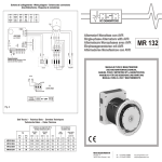
5) Collegare l'alternatore al quadro elettrico
P4/P6 unendo i connettori C e C1; effettuare
la messa a terra e l'eventuale collegamento
del carica batterie (vedi schema elettrico
Fig.2); bloccare il gruppo connettori allo
scudo, mediante innesto nella apposita sede
predisposta C2
5) Connect the alternator to the electric control
panel P4/P6 by joining the C and C1
connectors; after making the ground
connection and the connection to the batterycharger (see wiring diagram Fig.2); fasten the
connector unit to the shield by fitting it into the
C2 housing provided
5) Connectez l'alternateur au tableau électrique
P4/P6 en associant les connecteurs C et C1.
Mettez à la terre et connectez éventuellement
le chargeur de batteries (voir le schéma
électrique Fig.2). Solidarisez le groupe de
connecteurs à la flasque par emboîtement
dans le siège C2 prévu à cet effet
5) Den Wechselstromgenerator durch Verbinden
der Verbinder C und C1 an der Schalttafel
P4/P6 anschließen. Die Erdung und ggf. den
Anschluss des Batterieladegeräts ausführen
(siehe Schaltplan Fig.2); den Verbindersatz
durch Einrasten der entsprechenden,
vorbereiteten Aufnahme C2 am Lagerschild
blockieren
5) Conectar el alternador al cuadro eléctrico
P4/P6 uniendo los conectores C y C1;
efectuar la toma de tierra y la eventual
conexión del cargador de baterías (véase
esquema eléctrico Fig.2); fijar el grupo
conectores a la caja, acoplándolo en el
específico alojamiento predispuesto C2
6) Fissare il quadro elettrico all'alternatore,
utilizzando le 5 viti V4 (automaschianti M5×16)
in dotazione (4 viti nel caso di cuffia senza
prese o con P6)
6) Fasten the electric control panel to the
alternator using the 5 V4 screws (self-tapping
M5×16 screws) provided (or 4 screws for the
protection casing without sockets or with P6)
6) Solidarisez le tableau électrique et l'alternateur
à l'aide des 5 vis V4 (vis autotaraudeuses
M5×16) fournies en dotation (4 vis si le
protecteur n'a pas de prise ou avec P6)
6) Die Schalttafel mit Hilfe der 5 im Lieferumfang
enthaltenen, (selbsteinschneidenden M5×16)
Schrauben V4 (4 Schrauben im Falle der
Abdeckplatte ohne Steckdosen oder mit P6)
am Wechselstromgenerator befestigen
6) Fijar el cuadro eléctrico al alternador, utilizando
los 5 tornillos V4 (de rosca cortante M5×16)
incluidos en el suministro (4 tornillos si el
resguardo no tiene tomas o con P6)
7) chiudere il foro presente sul quadro elettrico P4
con il tappo in plastica P5, e quelli sul lato
posteriore dello scudo (se non utilizzati)
mediante i passacavi a membrana P1
7) close the hole on the electric control panel P4
using the P5 plastic plug; close the holes on the
shield (if not used) using the P1 membranetype cable glands
7) fermez le trou qui se trouve sur le tableau
électrique P4 à l'aide du bouchon en plastique
P5. Fermez les trous qui se trouvent sur la
flasque arrière (s'ils ne sont pas utilisés) à l'aide
des passe-câbles à membrane P1
7) die an der Schalttafel P4 vorhandene Bohrung
mit dem Kunststoffstopfen P5 und die
Bohrungen am hinteren Lagerschild (sofern sie
nicht genutzt werden) mit Hilfe von
Kabeldurchführungen mit Membrane P1
verschließen
7) cerrar el agujero que hay en el cuadro eléctrico
P4 con el tapón de plástico P5, y los que hay en
la caja trasera (si no se utilizan) mediante los
aisladores pasapanel de membrana P1
8) optional IP23: montare le due protezioni P2,
inserendole a scatto sullo scudo anteriore e
fissando ognuna con apposita vite V2
automaschiante M5×16
8) optional IP23: assemble the two P2
protections by snapping them into the front
shield and then fastening each one in place
using the appropriate V2 self-tapping M5x16
screw
8) option IP23: montez les deux dispositifs de
protection P2 en les encastrant sur la flasque
avant, puis fixez chacun d'eux à l'aide de la
vis V2 autotaraudeuse M5×16 prévue à cet
effet
8) Wahlweise IP23: Die beiden
Schutzeinrichtungen P2 durch Einrasten in
den vorderen Lagerschild und Befestigung
jeweils mit der entsprechenden,
selbsteinschneidenden V2 Schraube M5×16
einbauen
8) opcional IP23: montar las dos protecciones
P2, introduciéndolas a presión en la caja
delantera y fijando cada una con el relativo
tornillo de rosca cortante M5×16 V2
9) fissare l'alternatore al telaio utilizzando
supporti antivibranti adeguati
9) fasten the alternator to the frame using
appropriate vibration-damping supports
9) fixez l'alternateur au cadre au moyen des
supports antivibrants adéquate
9) den Wechselstromgenerator mit Hilfe von
Schwingmetallen am Rahmen befestigen
9) fijar el alternador al bastidor utilizando
soportes antivibrantes adecuados
Fig. 1D
Fig. 1C
P1
P1
C
C1
C
P4
P6
C1
V4
V4
P5
V2
P2
P1
C2
B
V2
P2
P1
C2
B
DF