1
pump driver.
Only when the locking lever shows “CLOSED” the oxygenator is
correctly inserted in the holder.
accessory lines connected to the device must be connected
tightly in order to prevent accidental introduction of air into the
device or blood loss.
7)
- Manually verify that the arterial filter and oxygenating module
are stably connected.
3)
PRIMING THE THERMOCIRCULATOR
Connect the water tubes to the holder by means of the female
Hansen connectors (SORIN GROUP ITALIA code 09028 or
equivalent).
- Connect the water tubes coming from the thermocirculator to
the oxygenator using Sorin Group Italia female Hansen
connectors.
- The use of different connectors from those indicated may
cause resistance inside the circuit and reduce the efficiency of
the heat exchanger.
- Do not obstruct the hole in the lower cover on the heat
exchanger as it is the outlet of the safety channel which helps
prevent fluids from crossing from one compartment to
another.
4)
CHECKING THE HEAT EXCHANGER
The device is checked by recirculating water in the exchanger for a few
minutes. The integrity of the structure is guaranteed if there are absolutely
no water leaks from the compartment or from the hole of the safety
channel.
5)
DEVICE SET-UP AND CONNECTIONS
- If oxygenated blood for blood cardioplegia needs to be used,
remove the red pos lock and connect the 1/4" blood line of the
cardioplegia circuit to the arterial blood access port of
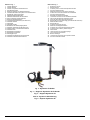
SYNTHESIS 4D (Ref. 16, Fig.1) by means of the adaptor
(provided with the product).
- If using the blood cardioplegia outlet during bypass, the line to
be connected must be open and not under pressure so that the
blood can flow into it.
6)
SAMPLING SYSTEM
a. If it is preferred to take samples from a more distant position,
remove the A/V sampling manifold (fig. 1, ref. 6) from its housing
and attach it on the dedicated holder. The tubing lines of the
sampling system allow positioning the manifold in a range of
about 1 meter. Position the stopcock handles toward the access
ports of the manifold (A/V shunt position).
b. Check the connection of the arterial sampling line to the Luer next to
the recirculation/purge Luer at the top of the arterial filter.
- The arterial sampling site connector Luer does not include a
one-way valve. Verify that there is a one-way valve in the
sampling line to prevent accidental air introduction into the
arterial line.
c. Check the connect ion of the venous sampling line to a Luer port
provided on the venous side of the device.
- Check that all the Luer connections are secure. All the
8)
VENTILATING GAS SUPPLY
Remove the green cap from the connector marked "GAS INLET" (Fig.
1, Ref. 14) and connect the 1/4" gas line. The gas must be supplied
through a suitable air/oxygen mixer. The connection for a capnograph
is obtained on the central axis of the "GAS ESCAPE" connector (Fig.
1, Ref. 15).
- The "gas escape" system was designed to prevent any
potential risk of occlusion of the gas outlet; such occlusion
would cause immediate passage of air to the blood
compartment.
9)
- All connections downstream of the pump must be secured by
means of ties.
Once the SYNTHESIS 4D has been positioned in the holder and the
centrifugal pump driver is put in place, complete the setup of the
remaining extracorporeal circuit components.
a. VENOUS RETURN. A 1/2" (12.7 mm) venous line can be attached
to the connector marked on the venous reservoir as "VENOUS
RETURN LINE" (Ref.2, Fig.1). The venous return connector can
be rotated 360° as needed.
b. SUCTION LINES. After removing the protective caps from the
"filtered" inlets on the top of the venous reservoir (four 1/4" / 6.35
mm inlets, two 3/8" / 9.53 mm inlets), connect the ends of the
suction tubes (Ref. 8, Fig.1) and rotate the turret orienting the
filtered inlets towards the suction pumps as desired.
c. ARTERIAL LINE: Verify that the 3/8" (9.5 mm) arterial line is
connected to the arterial filter outlet port. Connect the centrifugal
pump flow probe to circuit where desired.(Ref. 13 , Fig.1)
d. Remove the yellow cap from the vent connector marked
"VENT/VACUUM PORT" (Ref. 7, Fig.1) of the venous reservoir.
e. Verify that the arterial recirculation/purge line (Ref. 21, Fig.1)is
connected to the recirculation/purge Luer of the arterial filter, and
connect the opposite end of the recirculation/purge line to the
reservoir.
TEMPERATURE AND PRESSURE MONITORING
Use SORIN GROUP ITALIA temperature probes (code 09026) or
equivalent.
a. Connect the arterial temperature probe to the temperature probe
fitting (Ref. 17, Fig. 1), and connect the venous temperature probe to
the temperature probe fitting provided on the venous side of the
device (Ref. 3, Fig. 1).
b. To measure the oxygenator inlet pressure, connect a pressure
measurement line to the venous Luer close to the heat exchanger
inlet.
c. To measure oxygenator outlet pressure, connect a pressure
measurement line to the Luer port (Ref. 23, Fig. 1) close to the
arterial blood access port.
VAPOROUS ANAESTHETICS
The oxygenator is suitable for single use with volatile anaesthetic
isofluorane and sevofluorane, by means of a suitable narcosis gas
evaporator.
If these vaporous anaesthetics
are used, some method of
scavenging the gas from the oxygenator should be considered. The
protocol, the concentration and monitoring of the anaesthetic gases
administered to the patient is under the sole responsibility of the
physician performing the treatment.
An integral 3/8” (9.5 mm) gas scavenging fitting is available for this
purpose. It is located in the centre of the gas escape system. Connect a
piece of 3/8 x 3/32” (9.5 x 2.4 mm) tubing to this fitting and to a negative
pressure source with a flow rate in excess of the ventilating gas flow rate.
- The only volatile anaesthetics suitable for this use are
isofluorane and sevofluorane.
- The methods adopted for vaporous anaesthetic gas
scavenging should not in any way increase or reduce the
pressure level at the oxygenator fibres.
F. PRIMING AND RECIRCULATION
PROCEDURE
- Do not use alcohol based priming solutions as they can
compromise the structural integrity and functionality of the
device.
1)
CHECK THE HEAT EXCHANGER
Circulate water through the heat exchanger prior to priming the
oxygenator. Check the water system for leaks, proper water temperature
range, and adequate water flow. If a water to blood leak exists, water will
collect in the tubing connected to the oxygenator inlet/centrifugal pump
outlet port or drip from the hole in the bottom of the oxygenator module
indicating the device must not be used. The maximum pressure rating of
the heat exchanger is 2275 mmHg (300 kPa/ 44psi).
2)
3)
4)
5)
KEEP THE GAS FLOW CLOSED
CHECK THAT THE RECIRCULATION/PURGE
LINE IS OPEN
OCCLUDING THE VENOUS AND ARTERIAL
LINES
VENOUS RESERVOIR PRIMING
Secure with ties all the aspiration lines connected to the venous
reservoir. Fill the venous reservoir with sufficient liquid to ensure that
the intended hematocrit is obtained, taking into account that:
- the static priming volume of the oxygenator already including the
arterial filter is 525 ml;
- the 3/8" tube contains 72 ml/m;
- the 1/2" tube contains 127 ml/m.
6)
PRIMING THE CIRCUIT
- The pressure in the blood compartment of the oxygenator
GB – ENGLISH
7