1
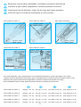
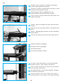
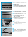
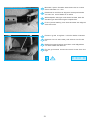
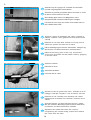
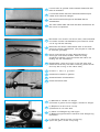
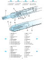
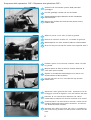
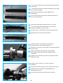
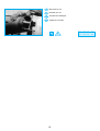
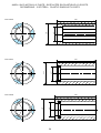
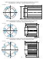
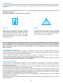
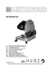
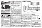
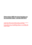
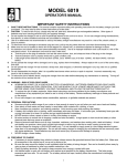
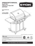
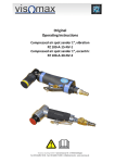
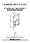
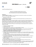
ALBERO PNEUMATICO A CHIAVETTE
ARBRE PNEUMATIQUE A TETONS
PNEUMATISCHE SPANNWELLE MIT KEILEN
AIR SHAFT WITH LUGS
ISTRUZIONI PER LA MANUTENZIONE
NOTICE D’ENTRETIEN
REPARATUR-ANWEISUNG UND ERSATZTEILLISTE
REPAIR INSTRUCTIONS AND SPARE PARTS LIST
SVECOM
SVECOM
SVECOM
SVECOM PE
I
Esaminare il tipo di albero espansibile verificando la posizione della valvola.
F
Individuer le type d’arbre expansible en vérifiant la position de la valve.
D
Untersuchen Sie die Wellenart, indem Sie die Lage des Ventils feststellen.
GB
Check the type of air shaft by checking the air valve position
TIPO-TYPE-TYP-TYPE A
TIPO-TYPE-TYP-TYPE B
TIPO-TYPE-TYP-TYPE C
VALVOLA - VALVE
VENTIL - VALVE
VALVOLA - VALVE
VENTIL - VALVE
VALVOLA - VALVE
VENTIL - VALVE
TIPO-TYPE-TYP-TYPE D
TIPO-TYPE-TYP-TYPE E
VALVOLA - VALVE
VENTIL - VALVE
VALVOLA - VALVE
VENTIL - VALVE
Una volta identificato il tipo corrispondente, per la sostituzione del tubo in gomma procedere come segue:
Lorsque vous avez individué le type d’arbre, pour la substitution de la vessie en gomme procédez comme il suit:
Haben Sie die entsprechende Art herausgefunden, ersetzen Sie das Gummischlauch wie folgt:
Once identified the type of shaft, please proceed as follows to replace the rubber tube:
I
F
D
GB
TIPO-TYPE-TYP-TYPE A
(da pag. 10 a 13)
(de pag. 10 à 13)
(von Seite 10 bis 13)
(from page 10 to 13)
TIPO-TYPE-TYP-TYPE B
(da pag. 10 a 13)
(de pag. 10 à 13)
(von Seite 10 bis 13)
(from page 10 to 13)
TIPO-TYPE-TYP-TYPE C
(da pag. 14 a 15)
(de pag. 14 à 15)
(von Seite 14 bis 15)
(from page 14 to 15)
TIPO-TYPE-TYP-TYPE D
(da pag. 17 a 19)
(de pag. 17 à 19)
(von Seite 17 bis 19)
(from page 17 to 19)
TIPO-TYPE-TYP-TYPE E
(da pag. 17 a 19)
(de pag. 17 à 19)
(von Seite 17 bis 19)
(from page 17 to 19)
9
AB
I
Sollevare il primo gruppo di chiavette e inserire dei
chiodini negli appositi foretti laterali.
F
Soulever le premier groupe de têtons et enfiler un fil de
fer dans l’orifice situé sur le côté.
D
Erste Keilgruppe heben und Nägelchen in die
entsprechenden seitlichen Bohrungen schlagen.
GB Lift the first set of lugs and insert some small rivets in the
suitable side holes.
I
Svitare i grani di fissaggio del perno dal lato della
valvola.
F
Dévisser les vis sans tête situées à l’extrémité de la
table.
D
Zapfen - Befestigungsschrauben auf der Ventilseite
abschrauben.
GB Unscrew the fixing grains of the valve side journal.
I
Svitare la valvola di gonfiaggio.
F
Dévisser la valve de gonflage.
D
Ventil abschrauben.
GB Unscrew the inflation air valve.
I
Avvitare l’asta dell’estrattore nell’apposita sede
assiale al per no. (vedi disegno estrattore).
F
Visser la tige filetée dans le trou axial du tourillon.
(voir plan de l’extracteur).
D
Auszieherstange in den entsprechenden Axialsitz
des Zapfens schrauben.
GB Screw the puller rod in the suitable seat which is
located axially to the jour nal. (see puller drawing).
10
I
Inserire la bussola, il tappo, la rondella e il dado.
(la bussola deve far battuta sul portante).
F
Positionner la bague, le couvercle, la rondelle l’écrou.
(la bague doit bûter sur la table).
D
Buchse, Deckel und Unterlegscheibe einsetzen.
GB
Insert the sleeve, the plug, the washer and the nut (the
sleeve must touch the shaft body).
I
Avvitare il dado in modo tale da estrarre il perno, e
con esso il tubo di gomma.
F
Visser l’écrou de façon à enlever le tourillon et donc
la vessie en gomme.
D
Mutter einschrauben und Wellenzapfen zusammen
mit dem Gummischlauch herausziehen.
GB T i g h t e n t h e n u t s o t h a t t h e j o u r n a l i s p u l l e d o u t
together with the rubber tube.
I
Togliere il grano e sfilare il tubo in gomma dal perno.
F
Dévisser la vis sans tête pour enlever la vessie du
tourillon.
D
Befestigungsschraube abnehmen und Gummischlauch
vom Zapfen trennen.
GB Remove the grain and slide out the rubber tube from the
journal.
I
Separare il tubo di gomma dai calici, svitando le viti di
fissaggio centrali e togliere i coni all’inter no del tubo.
F
D é v i s s e r l a v i s c e n t r a l e p o u r d é s s e re r l e s c ô n e s
d’étancheité et enlever les cônes à l’intérieur de la
vessie.
D
G u m m i s c h l a u c h v o n d e n K e l c h e n t re n n e n , i n d e m
Sie die mittleren Befestigungsschrauben und Konen
aus Gummischlauch nehmen.
GB S e p a r a t e t h e r u b b e r t u b e f r o m t h e c u p s b y
untightening the central fixing screws and remove
the cones from the tube.
11
I
Il nuovo tubo in gomma avrà le stesse dimensioni del tubo
da sostituire.
F
La nouvelle véssie aura les mêmes dimensions que celle
de la véssie à changer.
D
Das neue Gummischlauch hat die Maße des zu ersetzendes.
GB The new rubber tube will have the same dimensions as
the one to be replaced.
I
Rimontare coni e calici nel nuovo tubo, assicurandosi
che siano montati correttamente (vite forata e calice
con O-ring dal lato valvola).
F
Remonter les cônes d’étancheité dans la nouvelle
véssie et verifier l’étaucheité. (vis perçée du côte de
la valve de gonflage.
D
Konen und Kelche im neuen Gummischlauch
anbringen und darauf achten, daß sie richtig
angebracht werden. (Lochschraube und Kelch mit
O-Ring auf der Ventilseite).
GB Reassemble cones and cups in the new tube and
make sure that they are fitted correctly (bored screw
and cup with O-ring on the valve side).
I
Reinserire il tubo gomma nel perno fissandolo con
l’apposito grano.
F
Remettre la véssie en gomme à l’intérieur du tourillon et
revisser la vis sans tête.
D
Gummischlauch im Wellenzapfen wieder hineinstecken
und Befestigungsschraube anziehen
GB Insert the rubber tube in the journal and fix it with the
suitable grain.
I
Infilare il tubo in gomma nell’albero.
F
Introduire la véssie en gomme dans l’arbre.
D
Gummischlauch im Wellen-Körper hineinstecken.
GB Insert the rubber tube in the shaft.
12
I
Montare il perno facendo attenzione che le nicchie
siano allineate con i fori.
F
Remonter le tourillon en alignant les empreintes de
vis avec les trous filetés de la table.
D
Wellenzapfen anbrigen und darauf achten, daß die
Vertiefungen den Bohrungen entsprechen.
GB Fit the journal making sure that the seats are aligned
with the bores.
I
Fissare i grani e togliere i chiodini dalle chiavette.
F
Revisser les vis sans tête puis enlever les fils de
fer.
D
Befestigungsschrauben anziehen und Nägelchen
von den Keilen abnehmen.
GB Fix the grains and remove the small rivets from the
lugs.
!
13
M 8
M10
M12
Ms = 20
Ms = 40
Ms = 65
Nm
Nm
Nm
C
I
Sollevare il primo gruppo di chiavette e inserire dei
chiodini negli appositi foretti laterali.
F
Soulever le premier groupe de têtons et enfiler un fil de
fer dans l’orifice situé sur le côté.
D
Erste Keilgruppe heben und Nägelchen in die
entsprechenden seitlichen Bohrungen schlagen.
Lift the first set of lugs and insert some small rivets in
GB the suitable side holes.
A
B
I
Togliere il grano di fissaggio del calice, togliere il
seeger e sfilare il tubo gomma facendo presa sulla
valvola
F
Dévisser la vis sans tête, enlever le circlip puis la
vessie en gomme en tirant sur la valve
D
Kelch-Befestigungsschraube abnehmen. Seegerring
abnehmen und Gummischlauch herausziehen.
the fixing grain of the cup, remove the
GB Remove
circlip ring and slide out the rubber tube by gripping
on the air valve.
I
Svitare la valvola .
F
Dévisser la valve.
D
Ventil abschrauben.
GB Unscrew the air valve.
I
Separare il tubo di gomma dai calici, svitando le viti di
fissaggio centrale e togliere i coni all’interno del tubo.
F
Dévisser la vis centrale pour désserer les cônes
d’étancheité et enlever les cônes à l’intérieur de la
vessie.
D
Gummischlauch von den Kelchen trennen, indem
Sie die mittleren Befestigungsschrauben abdrehen
und Konen aus Gummischlauch nehmen.
GB Separate the rubber tube from the cups by
untightening the central fixing screws and remove
the cones from the tube.
14
I
Il nuovo tubo in gomma avrà le stesse dimensioni del
tubo da sostituire.
F
La nouvelle vessie aura les mêmes dimensions que
celles de la vessie à changer.
D
Das neue Gummischlaugh hat die Maße des zu
ersetzenden.
GB The new rubber tube will have the same dimensions as
the one to be replaced.
I
F
D
Rimontare coni e calici nel nuovo tubo, assicurandosi
che siano montati correttamente (vite forata e calice
con O-rig dal lato valvola).
Remonter les cônes d’étancheité dans la nouvelle
vessie et verifier l’étancheité. (Vis perçée du côté de
la valve de gonflage).
Konen und Kelche im neuen Gummischlauch
anbringen und darauf achten, daß sie richtig
angebracht werden (Lochschraube und Kelch mit
O-Ring auf der Ventilseite).
GB Reassemble cones and cups in the new tube and
make sure that they are fitted correctly (bored screw
and cup with O-ring on the valve side)
I
Infilare il tubo in gomma.
F
Introduire la vessie en gomme.
D
Gummischlauch hineinstecken.
GB Insert the rubber tube.
I
b) Montare la valvola e il seeger
a) Fissare il grano di bloccaggio, montare il seeger.
F
b) Replacer la valve et le circlip.
a) Revisser la vis sans tête.
D
b) Ventil und Seegerring anbringen
a) Befestigungsschraube anziehen und Seegerring
montieren.
b) Fit the air valve and the circlip ring
GB a) Fix the grain, fit the circlip ring.
15
I
F
VALIDO PER A-B
VALABLE POUR A-B
VALIDO PER A-B
VALID FOR TYPE A-B
C NON NECESSITA
DI ESTRATTORE
C L’EXTRACTEUR
NE SERT PAS
C NON NECESSITA
DI ESTRATTORE
TYPE C DOES NOT
NEED ANY PULLER
D
GB
2
5
4
3
1
12
11
13
14
4
8
7
6
9
10
I
1
2
3
4
5
6
7
8
9
10
11
12
13
14
Tubo di gomma
Chiavetta
Chiodino
Valvola
Grani di fissaggio
Estrattore
Dado
Tirante filettato
Perno dell’albero
Tubo portante
Grano bloccaggio calice
Vite bloccaggio gomma
Calice bloccaggio gomma
Cono bloccaggio gomma
1
2
3
4
5
6
7
8
9
10
11
12
13
14
Vessie eu gomme
Têton
Fil de fer
Valve
Vis sans tête
Extracteur
Ecrou
Tige filetée
Tourillon (axe)
Table
Vis sans tête
Vis centrale
Cône d’etancheité
Cône int. d’etancheité
D
1
2
3
4
5
6
7
8
9
10
11
12
13
14
Gummischlauch
Keil
Nägel
Ventil
Befestigungsstifte
Abzieher
Mutter
Gewindespindel
Wellenzapfen
Wellnkoerper
Becher-Befestigungsstift
Gummi-Befestigungsschraube
Gummi-Befestigungsbecher
Gummi-Befestigungskegel
1
2
3
4
5
6
7
8
9
10
11
12
13
14
Rubber tube
Expanding lug
Small rivet
Air valve
Fixing grain
Puller
Nut
Threaded rod
Shaft journal
Shaft body
Cup grain
Rubber fixing screw
Cup
Cone
16
F
GB
Sequenza delle operazioni D/E • Séquence des opérations D/E •
I
Svitare le viti che fissano il perno dalla parte del
gonfiaggio.
F
Du côté gonflage, enlever les vis de fixation.
D
Zapfen-Befestigungsschrauben auf der Ventilseite
ausschrauben.
GB Remove the screws which secure the journal on the
inflation side.
I
Sfilare il perno e con esso il tubo di gomma.
F
Enlever le tourillon et avec lui, la vessie en gomme.
D
Wellenzapfen mit dem Gummischlauch herausziehen.
GB Slide out the journal and the rubber tube together with it.
I
Fissare il perno in una morsa, svitare il calice e il tubo
in gomma.
F
Bloquer dans un étau le tourillon ensuite dévisser le
cône ainsi que la vessie.
D
Zapfen in Schraubstock befestigen und Kelch und
Gummischlauch abschrauben.
GB Put the journal in a vice, unscrew the cup and the
rubber tube.
I
Separare il tubo gomma dai calici, svitando le viti di
fissaggio centrali e togliere i coni all’inter no del tubo.
F
Dévisser la vis centrale pour déserrer les cônes
d’étancheité et enlever les cônes à l’intérieur de la vessie.
D
Gummischlauch von den Kelchen trennen, indem sie die
mittleren Befestigungsschrauben abdrehen, und Konen
aus Gummischlauch nehmen.
GB Separate the rubber tube from the cups by untightening
the central fixing screws and remove the cones from the
tube.
17
I
Il nuovo tubo in gomma avrà le stesse dimensioni del tubo
da sostituire.
F
La nouvelle vessie aura les mêmes dimensions que celles
de la vessie à changer.
D
Das neue Gummischlauch hat die Maße des zu
ersetzendes.
GB The new rubber tube will have the same dimensions as
the one to be replaced.
A
I
Assicurarsi dell’esatto montaggio dei coni. (foto B)
F
Les cônes d’étancheité doivent être correctement
montés et paralléles. (voir photo B).
D
Versichern Sie sich, daß die Konen korrekt montiert werden
GB Make sure the cones are fitted properly.
B
I
Avvitare il calice con vite forata nel lato valvola,
assicurandosi di aver montato l’anello OR
F
Revisser le cône avec vis perçée du côté valve et remettre
le joint torique.
D
Kelch mit gebohrter Schraube auf der Ventilseite
einschrauben. Versichern Sie sich, daß der O-Ring
montiert ist.
GB Tighten the cup with bored screw on the valve side after
fitting the O-ring.
I
Inserire il tubo in gomma, con il perno montato,
nell’albero.
F
Introduire la vessie en gomme et le tourillon dans l’arbre.
D
Gummischlauch, zusammen mit Wellenzapfen, im
Wellenkörper stecken.
GB Insert the rubber tube with the journal in the shaft.
18
I
Riavvitare le viti.
F
Revisser les vis.
D
Schrauben befestigen.
GB Tighten the screws.
!
19
M 8
M10
M12
Ms = 20
Ms = 40
Ms = 65
Nm
Nm
Nm
LATO COMANDO • COTE VALVE
VENTILSEITE • DRIVE SIDE
50
M10
M10
ø30
50
ø30
OR 4093
LATO NON COMANDO • COTE OPPOSÉ
GEGENÜBERLIEGENOE SEITE • NON DRIVE SIDE
VITE/VIS
SCHRAUBE/SCREW
CALICE/CÔNE
KELCH/CUP
CONO/CÔNE INT.
KONUS/CONE
CONO/CÔNE INT.
KONUS/CONE
CALICE/CÔNE
KELCH/CUP
VITE/VIS
SCHRAUBE/SCREW
COD./CODE
317020100
COD./CODE
3040001
COD./CODE
3050001
COD./CODE
3050001
COD./CODE
3040001
COD./CODE
317020100
50
M10
M10
ø35
50
ø35
OR 4112
VITE/VIS
SCHRAUBE/SCREW
CALICE/CÔNE
KELCH/CUP
CONO/CÔNE INT.
KONUS/CONE
CONO/CÔNE INT.
KONUS/CONE
CALICE/CÔNE
KELCH/CUP
VITE/VIS
SCHRAUBE/SCREW
COD./CODE
317020100
COD./CODE
3040001
COD./CODE
3050001
COD./CODE
3050001
COD./CODE
3040001
COD./CODE
317020100
50
50
M10
M10
ø40
ø40
OR 4131
VITE/VIS
SCHRAUBE/SCREW
CALICE/CÔNE
KELCH/CUP
CONO/CÔNE INT.
KONUS/CONE
CONO/CÔNE INT.
KONUS/CONE
CALICE/CÔNE
KELCH/CUP
VITE/VIS
SCHRAUBE/SCREW
COD./CODE
317020100
COD./CODE
3040001
COD./CODE
3050001
COD./CODE
3050001
COD./CODE
3040001
COD./CODE
317020100
50
ø45
50
M10
M10
ø45
OR 4150
VITE/VIS
SCHRAUBE/SCREW
CALICE/CÔNE
KELCH/CUP
CONO/CÔNE INT.
KONUS/CONE
CONO/CÔNE INT.
KONUS/CONE
CALICE/CÔNE
KELCH/CUP
VITE/VIS
SCHRAUBE/SCREW
COD./CODE
317020100
COD./CODE
3040001
COD./CODE
3050001
COD./CODE
3050001
COD./CODE
3040001
COD./CODE
317020100
20
LATO COMANDO • COTE VALVE
VENTILSEITE • DRIVE SIDE
LATO NON COMANDO • COTE OPPOSÉ
GEGENÜBERLIEGENOE SEITE • NON DRIVE SIDE
60
50
50
M12
M10
ø45
ø45
ø33,5
OR 4131
VITE/VIS
SCHRAUBE/SCREW
CALICE/CÔNE
KELCH/CUP
CONO/CÔNE INT.
KONUS/CONE
CONO/CÔNE INT.
KONUS/CONE
CALICE/CÔNE
KELCH/CUP
VITE/VIS
SCHRAUBE/SCREW
COD./CODE
317010120
COD./CODE
3040005
COD./CODE
3050005
COD./CONE
3100005
COD./CODE
3080005
COD./CODE
317010120
66
66
55
55
ø40
ø67
M16
M16
ø40
ø67
OR 6150
VITE/VIS
SCHRAUBE/SCREW
CALICE/CÔNE
KELCH/CUP
CONO/CÔNE INT.
KONUS/CONE
CONO/CÔNE INT.
KONUS/CONE
CALICE/CÔNE
KELCH/CUP
VITE/VIS
SCHRAUBE/SCREW
COD./CODE
317010160
COD./CODE
3040006
COD.
3050006
COD./CODE
3100006
COD.
3080006
COD./CODE
317010160
66
ø77
M16
M16
ø40
55
ø77
ø40
OR 6150
66
55
VITE/VIS
SCHRAUBE/SCREW
CALICE/CÔNE
KELCH/CUP
CONO/CÔNE INT
KONUS/CONE
CONO/CÔNO INT
KONUS/CONE
CALICE/CÔNE
KELCH/CUP
VITE/VIS
SCHRAUBE/SCREW
COD./CODE
317020100
COD./CODE
3040001
COD./CODE
3050001
COD./CODE
3050001
COD./CODE
3040001
COD./CODE
317020100
21
TUBO IN GOMMA • VESSIE EN GOMME • GUMMISCHLAÜCHE • RUBBER TUBE
ø10
ø15
ø40
20146030040
ø30
20146010015
201460150022
201460350045
ø22
ø45
ø35
ø15
201460190027
201460450060
ø19
201460280029
ø20
ø60
ø45
ø27
201460550070
ø28,5
ø25
ø35
22
ø70
ø55
201460250035
DISTANZIALI IN PLASTICA • INTERCALAIRES EN PLASTIQUE • DISTANZSTÜCK • PLASTIC
ø33
ANELLI IN PLASTICA A 3 PUNTE - SATELLITE EN PLASTIQUE A 3
DOIGTSDISTANZRING-3 SPITZEN - PLASTIC RING WITH 3 BITS
ø85
ø31
ø48
COD. 3030004
ø79
ø31
ø49
COD. 3030005
23
ø39
COD. 3030003
ø60
COD. 3030002
ø53
ø33
ø47
COD. 3030001
ANELLI IN PLASTICA A 3 PUNTE • SATELLITES EN PLASTIQUE A 3 DOIGTS
DISTANZRING - 3 SPITZEN • PLASTIC RINGS WITH 3 BITS
ø80
ø31
ø49
COD. 3030005
ø84
ø31
ø53
COD. 3030007
ø80
ø31
ø53
COD. 3030008
24
ANELLI IN PLASTICA A 3 PUNTE • SATELLITES EN PLASTIQUE A 3 DOIGTS
DISTANZRING - 3 SPITZEN • PLASTIC RINGS WITH 3 BITS
ø84
ø42
ø62
COD. 3030009
ANELLI IN PLASTICA A 4 PUNTE • SATELLITES EN PLASTIQUE A 4 DOIGTS
DISTANZRING - 4 SPITZEN • PLASTIC RINGS WITH 4 BITS
ø90
ø98
COD. 3030010
ANELLI IN PLASTICA A 6 PUNTE • SATELLITES EN PLASTIQUE A 6 DOIGTS
DISTANZRING - 6 SPITZEN • PLASTIC RINGS WITH 6 BITS
COD. 3030008
ø132
ø92
25
LATO COMANDO • VENTIL SEITE • COTE VALVE • DRIVE SIDE
COD. 311510029000000
COD. 311262621000145
OR 2025
G 3/8
G 1/8
Valvola tipo A (GD/29) - Esagono 17
Valve A (GD/29) - Exagone 17
Lufventil A (GD/29) - Sechskant 17
Air valve A (GD) - Exagone 17
14,5
29
OR 3056
Valvola tipo B (VI/145) - Esagono 11
Valve B (VI/145) - Exagone 11
Lufventil B (VI/145) - Sechskant 11
Air valve B (VI/145) - Exagone 11
COD. 311512614000000
COD. 311262620000017
OR 2025
17
14
OR 2025
G 1/8
G 1/8
Valvola tipo C (PD/14) - Esagono 12
Valve C (PD/14) - Exagone 12
Lufventil C (PD/14) - Sechskant 12
Air valve C (PD/14) - Exagone 12
Valvola tipo D (TR/17) - Esagono 11
Valve D (TR/17) - Exagone 11
Lufventil D (TR/17) - Sechskant 11
Air valve D (TR/17) - Exagone 11
OR 2025
23,5
COD. 311262619000235
G 1/8
Valvola tipo E (PT/235) - Esagono 11
Valve E (PT/235) - Exagone 11
Lufventil E (PT/235) - Sechskant 11
Air valve E (PT/235) - Exagone 11
26
CHIAVETTE • TETONS • KEILEN • EXPANDING LUGS
(H) Variabile a seconda dello spessore del tubo portante. • (H) Hauteur suivant l’epaisseur du tube de la table.
(H) Abhängig von der Tragrohr-Wandstärke • (H) Different depending on the body wall thickness
~ 99
H
~ 99
H
~ 99
H
27
AGENTS & DISTRIBUTORS
GENERAL DRIVE DE VENEZUELA, S.A.
SPAGNA
Centro comerolal Bello monte,
Piso 2 Caracas 1050 - Venezuela
Tel. 7527208 - Fax 7511579
Telex 28176 GEDRI VC
HERREKOR SL
Zamoka Lantegialdea
Oialume Bidea, 25 - Barrio Ergobia
20115 ASTIGARRAGA - Gipuzkoa
Tel. 943 55 64 50
Fax 943 55 28 09
AUSTRALIA
WEB DYNAMICS (SALES)
4/30 Lilian Fowler Place
Marrickville NSW 2204
Tel. 02 516 5533
Fax 02 516 5328
BELGIO
GERMANIA DEL NORD
GRECIA
G.M.E. SA
Gob Machinery Equipments
Chaussée de Stockel, 239
B - 1200 Bruxelles
Tel. 02 770 46 01
Fax 02 770 00 38
PETER A. KARANDINOS
P.O. Box 3551
10210 Athens - Greece
Tel. 1 322 9760
Fax 1 324 9275
ENGEL INDUSTRIEVERTRETUNG
Gaußstrasse 5
D - 31787 Hameln
Tel. 05151 67453
Fax 05151 67463
BRASILE
REGNO UNITO
MACCO Josè F Bianchi
Rua Fragária Rosea, 28
02945 - 000 - SÃO PAULO
Tel. 0055 011 85 48 222
Fax 0055 011 26 33 936
JARSHIRE LTD.
Levels House, Stoke Gardens
Slough SLI 3QE
Tel. 01753 825122
Fax 01753 694653
FRANCIA
GERMANIA DEL SUD
LAFORET DELAYE IND.
‘Le Futeau’
F - 38690 Colombe
Tel. 04 76 55 99 90
Fax 04 76 55 99 91
HAMANN INDUSTRIETECHNIK
Sonnenstrasse 6
D - 73230 Kirchhein/Teck
Tel. 07021 3085
Fax 07021 71393
ISRAELE
FINLANDIA
P.B.A. WIESNER LTD.
17, Bergman St.
Industrial Zone Sgula
Petach Tikva 49277
Israele
Tel. 03 905 21 11
Fax. 03 934 85 60
GRAAFINEN KONE OY
Läkkisepantie 20 B
SF - 00620 Helsinki
Tel. 9 799 655
Fax 9 796 066
SVIZZERA
STIREX AG
Kirchbergstrasse, 107
CH - 3400 Burgdorf
Tel. 0041 344 227 646
Fax 0041 344 233 894
Italy
LOMBARDIA/PIEMONTE/LIGURIA
CARELLI VALTER
Via Luigi Einaudi,10
20013 Magenta - MILANO
Tel 02 97297379
Fax 02 97950328
VENETO/FRIULI/VENEZIA GIULIA
TRENTINO ALTO ADIGE
DOTT. LUCIO MAZZAROL
Via S. Matteo, 14
36061 Bassano Del Grappa - VICENZA
Tel. e Fax 0424 30175
EMILIA ROMAGNA
MAURIZIO NERI
Via Parmeggiani 2/2
40131 BOLOGNA
Tel. e Fax 051 522282
ITALIA CENTRALE
B.F.G.& C. srl
Via Pesciatina, 599
55010 Gragnano - LUCCA
Tel. 0583 975878
Fax 0583 975879
ITALIA MERIDIONALE
MARIO TOMMASO TANI
Via Mimose ,2
00019 Tivoli
ROMA
Tel. 0774 330391
4- NIVEAUX DE DANGER
On conseille de lire très attentivement ce manuel et en particulier cette section concernant les normes de sécurité, afin
d’éviter des conduites inadéquates ou en contraste avec les instructions contenues dans le présent manuel.
Faire attention au signal de danger, là où il apparaît dans ce manuel, et se tenir aux dispositions de sécurité.
Les signaux de danger ici utilisés sont de deux niveaux:
!
AVERTISSEMENT
DANGER
Ce symbole signale que si les opérations décrites ne
sont pas correctement exécutées, elles risquent
d’endommager l’Arbre ou les matériaux enroulés. Ce
signal est valable pour toutes les opérations décrites
ci-après, même s’il n’est pas indiqué pour chacune
d’entre elles.
Ce signal indique que si les opérations décrites ne
sont pas correctement exécutées, elles risquent de
causer de graves lésions, la mort ou des risques à
long terme pour la santé.
La firme SVECOM - P.E. décline toute responsabilité pour les dommages directs ou indirects causés par
l’inobser vation de normes de sécurité et de prévention des accidents décrites ci-après.
5- UTILISATION SURE
• Il est absolument interdit d’utiliser ou de faire utiliser l’Arbre à quiconque n’aurait pas complètement lu, compris et
assimilé parfaitement les instructions du présent manuel et du manuel d’emploi et de maintenance de la machine dont
l’Arbre est un composant.
• Il est absolument interdit de toucher ou de s’appuyer sur l’arbre pendant la rotation.
• L’Arbre est construit exclusivement pour l’enroulement et le déroulement de matériau en bobine.
• Il est obligatoire de positionner la/les bobines de matériau enroulé sur l’Arbre suivant le schéma de chargement de
projet, communiqué à SVECOM - P.E. par document écrit et avalisé par celle-ci.
6- MAINTENANCE SURE
Pour garantir la maintenance sûre de l’Arbre, il est indispensable d’observer les prescriptions suivantes:
• La maintenance de l’Arbre ne doit être effectuée que par le personnel qualifié et spécialisé, suivant les instructions
fournies dans le présent manuel.
• La maintenance doit être scrupuleusement exécutée, conformément aux instructions contenues dans le présent manuel,
et en faisant remplacer les pièces endommagées ou usées.
• Toutes les opérations de levage de l’Arbre doivent être exécutées manuellement si la masse de l’Arbre est inférieure à la
limite établie ou à l’aide d’élingues adéquates et conformes aux Lois du Pays où les susdites opérations sont exécutées.
• Ne pas effectuer de soudures, ni de découpages au chalumeau ou avec un outil, ni de trous sur la structure de l’Arbre.
* Utiliser toujours des pièces détachées originales en cas d’interventions de dépannage et de maintenance.
• Pour les opérations de vissage de goujons et de vis, se servir de la clé dynamométrique étalonnée sur les valeurs
indiquées dans le texte.
• Mémoriser et conser ver, pendant toute la durée de vie de l’Arbre, le présent manuel d’emploi.
4
4- LEVELS OF DANGER
We recommend giving your full attention to this manual and to this section on safety standards in particular. This will help
to avoid actions that are undesirable or are in contrast with the instructions contained in this manual.
Pay attention to the danger signal when it is illustrated in this manual. Comply with safety regulations.
Danger signals used in this manual have two different meanings:
!
WARNING
DANGER
This symbol warns that if the operations described
are not correctly performed this can cause damage to
the Shaft or to the materials being reeled. This signal
is applicable for all the procedures described below
even if it is not specifically indicated for each of them.
This signal warns that the operations that are
described, if they are not correctly performed, can
cause severe harm, death or long term health risks.
SVECOM - P.E. declines all responsibility for direct or indirect damage caused by failure to comply with the safety
and accident prevention regulations described in the following paragraphs.
SVECOM - P.E. also declines all responsibility for damage caused by improper use of the Shaft and/or following
modifications to it that were not authorized by the manufacturer.
5- SAFE USE OF THE SHAFT
• It is prohibited to use or have the Shaft used by anyone who has not fully read, understood and perfectly assimilated the
contents of this manual and of the operating and maintenance manual for the machine where the Shaft is fitted.
• It is absolutely prohibited to touch or rest against the Shaft during rotation.
• The Shaft is built exclusively for reeling and unreeling materials in reels.
• It is mandatory to position the reel(s) of material wrapped on the Shaft according to the project loading schema
communicated to SVECOM - P.E. in a wr itten document and approved by this latter company.
6- SAFE MAINTENANCE
It is necessary to comply with the following regulations in order to guarantee safe maintenance of the Shaft:
• Maintenance on the Shaft must only be done by qualified and specialized personnel according to the instructions given
in this manual.
• Maintenance must be done with care, following the instructions contained in this manual and replacing damaged or worn
components.
• Any Shaft hoisting procedure must be done by hand if the mass of the Shaft is below the preset limit, or by suitable slings
that conform to the Laws of the Country where hoisting takes place.
• Never make weldings, flame or tool cuts or holes in or on the Shaft structure.
• Always use genuine spare parts when performing maintenance and repair.
• Use a torque wrench and the torque values indicated in the text when tightening dowels and screws.
• Memorize the contents of this Instruction Manual and preserve it for the entire working life of the Shaft.
8
4- LIVELLI DI PERICOLO
Si consiglia di leggere molto attentamente questo manuale ed in particolare questa sezione, che riguarda le norme di
sicurezza, evitando comportamenti inopportuni o in contrasto con le istruzioni contenute nel presente manuale.
Fare attenzione al segnale di pericolo, dove riportato, in questo manuale ed attenersi alle disposizioni di
sicurezza.
I segnali di pericolo qui impiegati sono di due livelli:
!
AVVERTENZA
PERICOLO
Questo simbolo avverte che se le operazioni descritte
non sono correttamente eseguite, si possono causare
danni all’Albero o ai materiali avvolti. Questo segnale
vale per tutte le operazioni descritte di seguito anche
se non riportato per ognuna di esse.
Questo segnale avverte che se le operazioni descritte
non sono correttamente eseguite, possono causare
gravi lesioni, morte o rischi a lungo termine per la
salute.
La SVECOM - P.E. declina ogni responsabilità per danni diretti o indiretti causati dalla mancata osservanza delle
norme di sicurezza e di prevenzione infortuni di seguito descritte.
La SVECOM - P.E. declina inoltre ogni responsabilità per danni causati da un uso improprio dell’Albero e/o a
seguito di modifiche eseguite senza autorizzazione del costruttore.
5- USO IN SICUREZZA
• È assolutamente vietato usare o fare usare l’Albero a chiunque non abbia letto completamente, compreso ed assimilato
perfettamente quanto riportato nel presente manuale, e nel manuale d’uso e manutenzione della macchina di cui l’Albero
è un componente.
• È assolutamente vietato toccare o appoggiarsi all’albero durante la rotazione.
• L’Albero è costruito esclusivamente per l’avvolgimento e lo svolgimento di materiale in bobina.
• È obbligatorio posizionare la/le bobine di materiale avvolto sull’Albero secondo lo schema di carico di progetto,
comunicato alla SVECOM - P.E. con documento scritto e da questa avvallato.
6- MANUTENZIONE IN SICUREZZA
Per garantire la manutenzione in sicurezza dell’Albero è indispensabile rispettare le seguenti prescrizioni:
• La manutenzione dell’Albero deve essere effettuata solamente da personale qualificato e specializzato, seguendo le
istruzioni riportate nel presente manuale.
• La manutenzione va eseguita scrupolosamente, seguendo le istruzioni contenute nel presente manuale e facendo
sostituire le parti danneggiate o usurate.
• Eventuali operazioni di sollevamento dell’Albero vanno eseguite manualmente se la massa dell’Albero è inferiore al limite
stabilito, o con imbracature idonee e conformi alle Leggi del Paese dove avvengono le suddette operazioni.
• Non effettuare saldature, tagli alla fiamma o con utensile o fori sulla struttura dell’Albero.
• Usare sempre negli interventi di riparazione e manutenzione ricambi originali.
• Per le operazioni di avvitamento di grani e viti fare uso della chiave dinamometrica tarata ai valori richiamati nel testo.
• Memorizzare e conservare per tutta la durata di vita dell’Albero il presente Manuale istruzioni d’uso.
2
4- GEFAHRSTUFEN
Es wird empfohlen, dieses Handbuch und insbesondere den Abschnitt, der die Sicherheitsvorschriften betrifft, aufmerksam zu lesen um
so ein unangebrachtes oder nicht den Anweisungen, die im vorliegenden Handbuch enthalten sind, entsprechendes Verhalten zu
vermeiden.
Beachten Sie das Gefahrenzeichen, wo es in diesem Handbuch aufscheint und halten Sie sich an die
Sicherheitsvorschriften.
Hier werden zwei Stufen von Gefahrenzeichen verwendet:
!
VORSICHT
GEFAHR
Dieses Zeichen warnt davor, daß eine unkorrekte
Ausführung der beschriebenen Tätigkeiten die Welle
oder das umwickelte Material beschädigen werden kann.
Dieses Zeichen gilt auch für alle in der Folge
beschriebenen Tätigkeiten, auch wenn es nicht jedesmal
wiedergegeben wird.
Dieses Zeichen warnt davor, daß eine unkorrekte
Ausführung der beschriebenen Tätigkeit schwere
Verletzungen, Tod oder eine lang anhaltende Gefahren
für die Gesundheit zur Folge haben kann.
Die Firma SVECOM - P.E. weist jede Verantwortung für direkte oder indirekte Schäden zurück, die durch Nichtbeachtung
der in der Folge angegebenen Sicherheitsvorschriften sowie der Vorschriften zur Vorbeugung von Unfällen entstehen.
Die Firma SVECOM - P.E. weist außerdem jede Verantwortung für Schäden zurück, die durch einen nicht sachgerechten
Gebrauch der Welle und/oder in der Folge von Veränderungen, die ohne die Bewilligung des Herstellers ausgeführt
wurden, entstehen.
5- ANWENDUNG IN SICHERHEIT
• Es ist strengstens verboten, die Welle zu betätigen oder betätigen zu lassen, wenn das vorliegende Handbuch sowie die
Gebrauchsanweisungen und Instandhaltungsvorschriften der Maschine, von der die Welle ein Bestandteil ist, vorher nicht ausführlich
gelesen und der Inhalt völlig verstanden und aufgenommen wurde.
• Es ist strengstens verboten, während der Rotation die Welle zu berühren oder sich auf sie zu stützen.
• Die Welle wurde ausschließlich für das Auf- und Abwickeln von Materialien auf Spulen konstruiert.
• Es ist Pflicht, die mit Material umwickelte/n Spule/n nach dem Belastungsschema des Plans zu positionieren, der der Firma SVECOM
- P.E. mit einem schriftlichen Dokument mitgeteilt und von ihr bestätigt wird.
6- WARTUNG IN SICHERHEIT
Um eine sichere Wellenwar tung zu garantieren, ist es unerläßlich, die folgenden Vorschriften zu beachten:
• Die Welle darf nur von qualifiziertem und Fachpersonal gewartet werden, wobei die Anweisungen, die im vorliegenden Handbuch
stehen, befolgt werden müssen.
• Die Wartung der Welle muß gewissenhaft ausgeführt werden, wobei die im vorliegenden Handbuch stehenden Anweisungen befolgt
sowie die beschädigten oder abgenutzten Teile ersetzt werden müssen.
• Das eventuelle Aufheben der Welle muß manuell erfolgen, wenn das Gewicht der Welle unter der festgesetzten Grenze liegt oder mit
Schlingen, die geeignet sind und den Gesetzen des Landes entsprechen, in dem die obengenannten Tätigkeiten durchgeführt werden.
• Auf der Struktur der Welle nicht schweißen, brennschneiden, mit Werkzeug schneiden oder Löcher bohren.
• Bei den Reparatur- und Wartungsarbeiten immer originale Ersatzteile verwenden.
• Beim Einschrauben von Dübeln und Schrauben muß ein Drehmomentenschlüssel verwendet werden, der auf die im Handbuch
angegebenen Werte eingestellt ist.
• Das vorliegende Handbuch mit den Gebrauchsanweisungen für die ganze Lebensdauer der Welle aufbewahren und den Inhalt im
Gedächtnis festhalten.
6