1
4. Route the 2-pole connecting cable (6) with insulating
tape parallel to the system
regulator (7) and gas pipe (8).
5. Route cable to the inside, to the place where the
control panel is to be installed. Lengthen using a 2 x
0.75 mm² cable, if necessary.
The electrical connection or the connection to a cable extension must not be effected
in the cylinder container.
For passing cables through
a cylinder container (9), use
rubber grommets or bodywork sealing material. Establish the cable run at least
50 cm above the base of the
cylinder container, or lay it
inside a protective tube.
Electrical connection
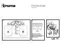
1. Fig. C: Choose a place for
the control panel (10) in a position which is easy to view.
If it is not possible to
install the control panel
flush with the surface, Truma
can provide a surface-mounting frame (11) on request, as
a special accessory (part no.
40000-52600).
2. Drill two holes of 55 mm
diameter. Guide the connection cable for the pressure
switch (6) and the 12 V feed
cable (17) from the rear
through the drillhole in the
wall and connect it to the
control panel in accordance
with the connecting diagram.
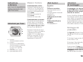
Fig. B: Connecting diagram
1 = Feed cable, 12 V positive
2 = Feed cable, negative
3 = Eis-Ex ice preventer
4 = Eis-Ex ice preventer
5 = Negative lead (black)
from pressure switch
6 = Positive lead (red) from
pressure switch
The terminals 3 and 4 are
intended for the connection
of one or two Eis-Ex ice preventers. These connection
6
cables can be connected
wherever convenient.
3. Fig. C: Fit the rear cover
cap (14) as a stress-relieving
device, then secure the control panel (10) with 4 screws
(12) and fit the cover frame
(15).
Truma can supply side
pieces (16) as special
accessories to round off the
cover frame.
4. Connect appliance to fused
vehicle power supply (central
electrical system 5 – 10 A)
using a cable 2 x 0.75 mm².
The negative lead is to be
connected to the central
ground. When connecting
directly to the battery, always
fuse the positive and negative
lead.
When power supplies
are being used, it must
be noted that the output
voltage is between 11 V and
15 V and the alternating
current ripple is < 1.2 Vpp.
With the Truma transformer
connector (part no. 53110-01)
the remote indicator can also
be operated with 230 V. The
transformer connector
supplies a 12 V alternating
current with low power. The
two cables on the transformer connector can be connected in any order. With the
transformer connector it is
only possible to operate one
defroster (Eis-Ex – it is not
possible to connect any other
12 V appliances).
Function test
After installation the sealing tightness of the gas pipe
must be tested, by using the
pressure drop method; thereafter, check all functions in
accordance with the
Operating instructions.
The Operating Instructions
are to be handed over to the
user.