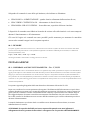
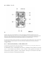
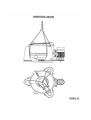
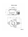
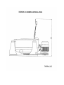
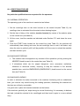
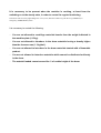
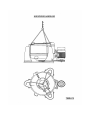
1
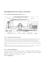
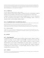
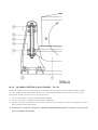
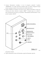
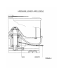
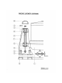
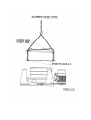
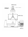
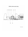
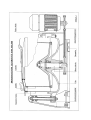
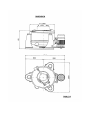
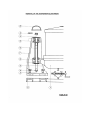
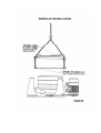
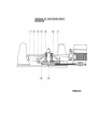
E090405X 02/04/09 ISTRUZIONI D’USO MANUTENZIONE E INSTALLAZIONE INSTALLATION MAINTINANCE AND USE MANUAL ZP 900SEL IMESA S.p.A. Via degli Olmi 22 31040 Cessalto (TV), Italia tel. +39.0421.468011 fax +39.0421.468000 www.imesa.it INDICE GENERALE Pag. 01 RIEPILOGO DATI MARCATURA MACCHINA 3 02 USO DEL MANUALE DI ISTRUZIONE 4 03 USO PREVISTO – GENERALITA’ 4 03.1 Uso previsto 03.2 Caratteristiche generali 03.3 Natura del rischio 4 4 5 DESCRIZIONE TECNICA DELLA MACCHINA 6 04.1 Parti strutturali ed organi 6 04 04.1.1 04.1.2 04.1.3 04.1.4 04.1.5 04.1.6 Fondo/Vasca di raccolta Fasciame esterno Basamento Cestello Coperchio bocca di apertura (oblò) Albero centrale 04.2 Gruppi 04.2.1 04.2.2 04.2.3 04.2.4 05 06 Trasmissione Freno Gruppo sospensione Quadro elettrico di comando 6 6 7 7 7 7 7 7 8 8 9 04.3 Rumore 11 INSTALLAZIONE 11 05.1 Disimballaggio e livellamento 05.2 Scarico acqua 05.3 Collegamenti elettrici 11 12 12 PROCEDURA DI AVVIAMENTO 13 06.1 Dare energia 06.2 Controllo senso di rotazione 13 13 13 07 DISPOSITIVI DI SICUREZZA: FUNZIONAMENTO E CONTROLLO 08 09 07.1 Dispositivo antioscillazione 07.2 Dispositivo di sicurezza apertura coperchio 13 14 ISTRUZIONI PER L’USO 16 08.1 Operazione normale 08.2 Arresto macchina 08.3 Caricamento macchina 16 17 17 MANUTENZIONE 18 09.1 Lubrificazione 09.2 Cuscinetti 09.3 Freno 09.3.1 Regolazione traferro 09.3.2 Regolazione coppia frenante 18 18 18 19 19 19 10 ISTRUZIONI PER LO SMONTAGGIO 10.1 10.2 10.3 10.4 10.5 11 Rimozione cestello Rimozione fasciame esterno Rimozione cestello Rimozione cuscinetti albero centrale Rimozione cinghie di trasmissione RIEPILOGO DATI MACCHINA 19 19 20 20 21 21 INDICE DELLE TAVOLE TAVOLA I TAVOLA II TAVOLA III 6-31 9 10 22 TAVOLA IV 23 TAVOLA V 24 TAVOLA VI 25 TAVOLA VII 14 TAVOLA VIII 16 TAVOLA IX 26 TAVOLA X 18 TAVOLA XI 27 TAVOLA XII 28 TAVOLA XIII 29 TAVOLA XIV 30 TAVOLA XV ALLEGATO: SCHEMA ELETTRICO RIEPILOGO DEI DATI DELLA MARCATURA DELLA MACCHINA • MARCHIO – LOGO – SOCIETA’: M.S.L. MECCANICA S.r.l. Via Forrenera, 2 51019 PONTE BUGGIANESE (PT) • IL FABBRICANTE: • MARCATURA: M.S.L. Meccanica S.r.l. MARCHIO • MACCHINA: IDROESTRATTORE CENTRIFUGO • MODELLO: SEL/900 • MATRICOLA:______________________________ • RPM: 1100 • CAPACITA’ DI CARICO: 57 Kg • POTENZA INSTALLATA: 7,5 Kw • ANNO DI COSTRUZIONE: ______________ USO DEL MANUALE D’ISTRUZIONE Il manuale tecnico è indirizzato al personale preposto all’uso, all’installazione, alla manutenzione e alla riparazione guasti. E’ necessario leggere attentamente i capitoli specifici per poter operare in sicurezza nell’uso, l’installazione, la manutenzione e le riparazioni dell’idroestrattore. Il costruttore si riserva il diritto di aggiornamento del manuale senza obbligo di “retrofit”. Il costruttore si ritiene sollevato da ogni responsabilità nei seguenti casi: • • • • • • • • • • Il caricamento della macchina non avvenga nei modi indicati nel manuale; Non vengono osservate le indicazioni per l’installazione; Non venga fatta la manutenzione secondo quanto previsto nel manuale; Vengano elusi o non controllati, con periodicità prevista, i dispositivi di sicurezza che impediscono la rotazione del cestello con coperchio anche parzialmente aperto; Venga eluso o non controllato con la periodicità prevista il dispositivo antivibrazione; Vengano effettuate modifiche o interventi non autorizzati; Vengano centrifugati materiali con densità superiore a quella prevista; Vengano centrifugate masse superiori a quelle indicate in targhetta; Venga introdotto nel cestello materiale che non sia possibile distribuire uniformemente; Venga introdotto nel cestello materiale trattato con sostanze infiammabili. USO PREVISTO – GENERALITA’ 03.1 – USO PREVISTO L’idroestrattore centrifugo mod. SEL/900 è impiegato principalmente per disidratare biancheria, prodotti dell’industria tessile o altri prodotti, purché la loro massa volumica non superi 1,3 Kg/dmc. Il carico massimo centrifugabile, al massimo numero di giri: 57 Kg a 1100 rpm. 03.2 – CARATTERISTICHE GENERALI L’idroestrattore centrifugo mod. SEL/900 è ad asse verticale e sospensione elastica, in esso la forza di richiamo al centro è dovuta unicamente al peso. In questo tipo di macchina il fondo/vasca di raccolta è sospeso mediante tre tiranti incernierati con snodo elastico a tre colonnini disposti a 120° tra loro; il fondo/vasca di raccolta, centralmente, porta un albero conico sul quale è calettato il cestello. Il fondo/vasca di raccolta così sospeso ai tre tiranti si comporta come una massa pendolare con un proprio periodo di oscillazione e pertanto gli spostamenti da esso subiti nella fase di avviamento, sotto l’azione della forza centrifuga generata dalla massa non equilibrata dovuta al materiale posto nel cestello, rapidamente si riducono non appena il numero di giri del cestello (ovvero il suo periodo di rotazione) supera il periodo di oscillazione del fondo/vasca di raccolta. Gli elestomeri in gomma neoprene posizionati sui tiranti (n.4 per ogni tirante) hanno la funzione: 1. di ammortizzare le sollecitazioni dovute alla coppia generata dalla forza centrifuga non equilibrata che tende a sollevare il fondo/vasca di raccolta; 2. di generare una coppia sulle cerniere in modo da ostacolare gli spostamenti del fondo/vasca di raccolta. 03.3 – NATURA DEL RISCHIO I rischi connessi all’uso dell’idroestrattore derivano principalmente dalla rotazione del cestello con coperchio oblò anche parzialmente aperto: • Apertura del coperchio oblò con cestello in rotazione; • Apertura accidentale, anche parziale, del coperchio oblò con cestello in rotazione; • Azionamento della macchina con coperchio oblò anche parzialmente aperto; • Funzionamento dell’idroestrattore con carico sbilanciato. Un carico eccessivamente sbilanciato può originare una forza centrifuga sul cestello, tale da compromettere la resistenza meccanica dell’albero centrale e dei cuscinetti e, nello stesso tempo, originare delle oscillazioni eccessive fino al collasso delle sospensioni. DESCRIZIONE TECNICA DELLA MACCHINA 04.1 – PARTI STRUTTURALI ED ORGANI – Tav. I 04.1.1 – FONDO/VASCA DI RACCOLTA Il fondo/vasca di raccolta, costruito in robusta fusione di ghisa opportunamente lavorata di macchina utensile, porta le sedi su cui sono articolati gli elastomeri in gomma, la cerniera della sospensione, l’alloggiamento dei cuscinetti dell’albero centrale, la cerniera per l’articolazione della piastra motore, la sede per l’ancoraggio del fasciame esterno, inoltre raccoglie il liquido centrifugato e attraverso una canalizzazione lo convoglia all’esterno verso lo scarico. L’azione di scarico del liquido è accelerata dal vortice di aria generato dalla rotazione del cestello che agisce in senso tangenziale con verso coincidente con la canalizzazione di scarico. La massa complessiva del fondo/vasca di raccolta, del cestello, di tutte le parti connesse e del carico posto nel cestello, originano la forza di richiamo a centro che si oppone alle sollecitazioni dovute allo sbilanciamento del carico stesso. 04.1.2 – FASCIAME ESTERNO Il fasciame esterno ha il duplice compito: provvedere al contenimento del liquido centrifugato e a proteggere il cestello. E’ costruito in lamiera di acciaio inossidabile ed è ancorato, mediante flangiatura, al fondo/vasca di raccolta con n. 6 viti M 10. 04.1.3 - BASAMENTO Il basamento realizzato in robusta fusione di ghisa, lavorato di macchina utensile, consente l’ancoraggio a terra della macchina, esso è provvisto di tre piani di appoggio disposti a 120° sui quali vengono fissati i colonnini della sospensione. Il basamento viene ancorato alla fondazione con sei arpioni di fondazione (tirafondo) opportunamente calcolati per resistere alle forti sollecitazioni dovute a un funzionamento con carico anche fortemente sbilanciato. 04.1.4 - CESTELLO I l cestello è composto essenzialmente da due parti: fondo e il mantello. Il fondo, realizzato in robusta fusione di ghisa e carpenteria di acciaio ed è interamente rivestito in lamiera di acciaio inossidabile, porta la sede conica per l’accoppiamento con l’albero motore. Il mantello è realizzato in lamiera forata di acciaio inossidabile spessore 3 mm ed è rinforzata da due fasce, una superiore ed una inferiore e da due anelli di blindaggio centrali. L’unione tra mantello e fondo è realizzata mediante saldatura elettrica. 04.1.5 – COPERCHIO BOCCA DI APERTURA (OBLO’) La macchina porta, nella parte superiore, un coperchio per impedire che il materiale da centrifugare fuoriesca dall’idroestrattore durante il funzionamento e per evitare che si possa accedere nel cestello quando questo è in movimento. Il coperchio è incernierato ad una scatola posta sulla copertura del fasciame esterno; l’apertura e la chiusura è manuale ed è regolata da dispositivi di sicurezza che ne impediscono l’azionamento quando la macchina è in funzione (cestello in rotazione). 04.1.6 – ALBERO CENTRALE L’albero centrale, costruito in acciaio speciale di adeguate dimensioni, è supportato da tre cuscinetti, due superiori (uno a rulli cilindrici e uno reggispinta) ed uno inferiore (a rulli cilindrici). La lubrificazione è effettuata con grasso tramite ingrassatore posto, in posizione opportuna, sul fondo/vasca di raccolta. 04.2 - GRUPPI 04.2.1 – TRASMISSIONE La trasmissione del moto, dal motore elettrico all’albero centrale sul quale è calettato il cestello, è effettuata con pulegge a tre gole e cinghie trapezoidali B84. La regolazione della tensione delle cinghie è realizzata con piastra motore a cerniera azionata da puntone. La messa in funzione dell’idroestrattore avviene agendo sull’alimentazione del motore elettrico. L’avviamento e la frenatura sono realizzati in maniera tale da evitare gli slittamenti delle cinghie di trasmissione. L’alimentazione del motore elettrico è in corrente alternata trifase con tensione di 380 V e frequenza 50Hz, la sua potenza è 7,5 Kw. 04.2.2 – FRENO L’idroestrattore è provvisto di un freno elettromagnetico per la frenatura di servizio e di emergenza. Il freno è a bordo del motore elettrico ed agisce direttamente sull’albero dello stesso. La frenatura avviene per diseccitazione degli elettromagneti; con questo sistema di frenatura si ha l’arresto dell’idroestrattore in caso di interruzione dell’alimentazione elettrica. La frenatura di servizio è regolata da due temporizzatori: il primo temporizzatore posto sul quadro elettrico di comando determina il ciclo di centrifugazione (scelto dall’operatore), il secondo temporizzatore, posto all’interno del quadro elettrico di comando, regola l’inizio della frenatura (tarato in fabbrica). Trascorso il tempo di centrifugazione, impostato sul temporizzatore posto sul quadro di comando (vedi Tav. III), interviene il secondo temporizzatore con la funzione specifica di ritardare (massimo 60 sec.) l’intervento del freno. Trascorso il tempo di ritardo, impostato sul secondo temporizzatore, inizia l’azione frenante del motore fino all’arresto dello stesso. Con questo artificio tecnico si ottiene una decelerazione del motore senza l’intervento del freno e, successivamente, una frenatura più dolce, di conseguenza una maggiore durata delle parti usurabili del freno stesso. La frenatura di emergenza, al contrario di quella di servizio, avviene direttamente, senza l’intervento della decelerazione, per fermare la macchina nel più breve tempo possibile. 0.4.2.3 – GRUPPO SOSPENSIONE – Tav. II Il fondo /vasca di raccolta (part. 1) con tutte le parti annesse è appeso a tre colonnini (part. 5), solidali al basamento (part. 2); il collegamento fondo/vasca di raccolta – colonnini è realizzato con tre tiranti (part. 6). Nella parte superiore dei colonnini e nelle mensole di sospensione del fondo/vasca di raccolta (part. 4) sono inseriti degli elastomeri in gomma neoprene (part. 3) che hanno la funzione di ostacolare gli spostamenti del fondo, di ammortizzare le sollecitazioni dovute alla coppia generata dalla forza centrifuga non equilibrata che tende a sollevare il fondo. 04.2.4 - QUADRO ELETTRICO DI COMANDO – Tav. III Il quadro di comando contiene tutti i dispositivi elettrici, elettromeccanici ed elettronici per il funzionamento dell’idroesttrattore, deve essere posizionato nelle vicinanze della macchina. Esso è collegato al pannello di comando con un cavo di circa tre metri. Dal quadro di comando si possono eseguire le seguenti operazioni: 1) Avviare l’idroestrattore centrifugo premendo il pulsante “MARCIA”. 2) Arrestare l’droestrattore centrifugo premendo il pulsante “ARRESTO”. 3) Impostare il tempo di centrifugazione sul temporizzatore posto sul quadro di comando, il tempo di centrifugazione è calcolato dall’avviamento all’inizio della frenatura. 4) Selezionare la velocità di rotazione (versione con inverter) mediante il selettore a tre posizioni posto sul quadro di comando. 5) Arrestare l’idroestrattore centrifugo, in caso di emergenza, premendo il pulsante “EMERGENZA”. Per rendere operativa la macchina, dopo aver attivato l’emergenza, bisogna riarmare il pulsante ruotando lo stesso nella direzione indicata dalla freccia. 6) Eseguire il RESET per oscillazioni o vibrazioni eccessive. Qualora l’idroestrattore si arresta, per l’intervento del sensore vibrazioni, il pulsante “RESET” si illumina; dopo aver verificato il motivo dell’intervento del sensore, per ripristinare il funzionamento dell’idroestrattore occorre premere il pulsante “RESET”. 7) Impostare il tempo di ritardo della frenatura, agendo sul temporizzatore, posizionato all’interno del quadro di comando. 8) Togliere alimentazione elettrica all’idroestattore, agendo sull’interruttore generale . Sul quadro di comando ci sono delle spie luminose, che indicano se illuminate: • SPIA BIANCA: ALIMENTAZIONE – quadro elettrico alimentato dalla tensione di rete; • SPIA VERDE: CENTRIFUGA ON – idroestrattore in fase di lavoro; • SPIA ROSSA: SBLOCCO FRENO – freno sbloccato, coperchio oblò non vincolato. I dispositivi di comando sono fabbricati in modo da resistere alle sollecitazioni a cui sono sottoposti durante il funzionamento e all’azionamento. Gli errori di logica nei comandi non sono possibili perché momento per momento la macchina accetta solo comandi congrui con la sequenza operativa. 04.3 - RUMORE Per quanto riguarda l’emissione di rumore aereo, l’idroestrattore non costituisce un fattore di rischio visti i modesti valori della pressione acustica al posto di lavoro. I rilievi fonometrici effettuati su un identico modello di questa macchina, in condizioni di normale funzionamento, sono: Leq(A) < 70 dB L(lin) < 70 dB Lpc < 130 dB Non bisogna installare l’idroestrattore centrifugo in zona riverberante. INSTALLAZIONE 05.1 – DISIMBALLAGGIO E LIVELLAMENTO – Tav. V,VI,VII Tutte le operazioni di scarico e movimentazione devono essere effettuate da personale specializzato in trasporti e movimentazioni di oggetti pesanti. Dopo aver tolto l’imballo esterno della macchina procedere alla movimentazione, la macchina è ancorata al pallett di legno per consentire la movimentazione con carrello elevatore. Dopo aver trasportato la macchina nel punto di installazione si deve posizionare la stessa sulla fondazione precedentemente realizzata in cemento armato come indicato dal disegno di fondazione, vedi tavola V, con i punti di ancoraggio dei tiranti in corrispondenza dei relativi pozzetti e lo scarico in corrispondenza dello scarico realizzato nella fondazione. Per quanto riguarda gli ingombri della macchina fare riferimento alla tavola VI e VII. Dopo aver verificato la corretta posizione ed eseguito il livellamento dell’idroestrattore si può colare cemento liquido nei pozzetti con i tiranti di fondazione in posizione. Solo dopo un congruo tempo (10 giorni) tale da consentire il totale consolidamento del cemento, si possono bloccare i tiranti. Dopo il bloccaggio definitivo dei tiranti controllare nuovamente il livellamento che può essere riferito alla bocca del cestello. Un livellamento non corretto dell’idroestrattore può causare vibrazioni pericolose durante il funzionamento. I tiranti di fondazione con relativo dado e rondella sono in dotazione alla macchina; si trovano imballati dentro il cestello. ATTENZIONE: il coperchio dell’oblò può essere aperto allorquando sono stati effettuati i collegamenti elettrici, pertanto la macchina è consegnata con il coperchio oblò PARZIALMENTE APERTO per poter estrarre dal cestello gli accessori in dotazione e, quindi procedere all’installazione definitiva. Non mettere in funzione l’idroestrattore centrifugo prima di aver provveduto al fissaggio definitivo. 05.2 – SCARICO ACQUA L’ idroestrattore centrifugo ha un solo punto di scarico, che deve essere posizionato sopra il pozzetto di scarico realizzato nella fondazione. Se non è predisposto il pozzetto di scarico nella fondazione occorre assicurarsi che il punto di scarico sia ad un livello più basso del collettore di scarico dell’idroestrattore. 05.3 – COLLEGAMENTI ELETTRICI I collegamenti elettrici devono essere effettuati unicamente collegando i cavi di alimentazione più il cavo di terra alla morsettiera posizionata all’interno del quadro di comando in corrispondenza dei morsetti contrassegnati dalle lettere R S T (vedi schema elettrico). Inoltre devono essere collegati tutti gli altri cavi di potenza e di servizio alla morsettiera che servono per connettere l’idroestrattore al quadro elettrico (tutti i cavi nonché la morsettiera sono univocamente identificati). E’ necessario controllare la rispondenza delle caratteristiche di erogazione dell’energia elettrica (tensione, frequenza, numero di fasi) con le caratteristiche di alimentazione dell’idroestrattore centrifugo prima di procedere al collegamento alla rete. La sezione dei cavi deve essere ampiamente dimensionata rispetto alla potenza installata e alla lunghezza del cavo di alimentazione. Tutti i collegamenti elettrici sono indicati nello schema elettrico allegato a questo manuale. Tutti i segnali di servizio sono a bassa tensione di sicurezza: 24 Volts. La macchina deve essere alimentata con corrente elettrica trifase a 380/400 volts e frequenza 50 hertz. La potenza installata: 7,5 Kw. Dopo aver effettuato le operazioni di cui ai punti 05.1; 05.2; 05.3 l’installazione è completata. PROCEDURA DI AVVIAMENTO Dopo aver effettuato l’installazione dell’idroestrattore come indicato ai punti 05.1; 05.2; 05.3 si devono eseguire operazioni prima di procedere all’avviamento della macchina. 06.1 – FORNIRE ENERGIA Fornire energia elettrica alla macchina agendo sull’interruttore generale: ruotare l’interruttore generale nella posizione “1”. 06.2 – CONTROLLO SENSO DI ROTAZIONE E’ importante controllare il senso di rotazione del cestello, che deve essere quello indicato dalla freccia disegnata sull’adesivo posto sul coperchio oblò (senso orario). Nel caso che il senso di rotazione non fosse orario, invertire le fasi elettriche di alimentazione del motore. Dopo aver effettuato le operazioni di cui ai punti 06.1; 06.2; la macchina è pronta per operare. DISPOSITIVI DI SICUREZZA: FUNZIONAMENTO E CONTROLLO 07.1 – DISPOSITIVO ANTIOSCILLAZIONI Per evitare gli inconvenienti dovuti alla forza centrifuga generata da un carico eccessivamente sbilanciato, l’idroestrattore è dotato di un dispositivo, sensibile alle oscillazioni e alle vibrazioni della macchina, il quale provvede ad arrestare la macchina qualora le oscillazioni e le vibrazioni dovessero raggiungere limiti pericolosi. Tale dispositivo è costituito essenzialmente da un sensore magnetico di prossimità, posizionato in una mensola di sospensione del fondo/vasca di raccolta. Quando, per effetto delle oscillazioni del fondo/vasca di raccolta, la distanza tra il sensore di prossimità ed un elemento metallico (vite), posizionato nel colonnino, scende sotto il valore di taratura viene attivato il sensore magnetico di prossimità il quale comanda l’arresto dell’idroestrattore. Il funzionamento di questo dispositivo è fondamentale per la sicurezza della macchina per cui è necessario controllare periodicamente la sua taratura. Al momento della messa in servizio dell’idroestrattore e successivamente con periodicità almeno mensile è necessario controllare il corretto funzionamento del dispositivo antioscillazioni. Per verificare il corretto funzionamento e l’eventuale taratura del dispositivo antioscillazione procedere nel seguente modo: applicare una massa di 3,5 Kg all’interno del cestello, sul raggio massimo e sulla metà dell’altezza utile, far partire la macchina facendole raggiungere il regime. Se la macchina si arresta, per l’intervento del dispositivo antioscillazioni causato dalle oscillazioni prodotte dalla massa applicata all’interno del cestello, il sensore è correttamente tarato. Se la macchina non si arresta ovvero si ferma molto prima di raggiungere il regime significa che il sensore magnetico non è correttamente tarato; in questo caso consultare il Servizio Tecnico del produttore. 07.2 – DISPOSITIVI DI SICUREZZA APERTURA COPERCHIO OBLO’ – Tav. VIII e IX L’idroestrattore centrifugo è stato dotato di un dispositivo elettromeccanico, posizionato all’interno di una scatola posta sul fasciame esterno (Tav. VIII), che ha il compito di impedire: • L’apertura del coperchio con cestello in rotazione; • La rotazione del cestello con coperchio anche parzialmente aperto; • L’avviamento dell’idroestrattore con coperchio aperto o anche parzialmente aperto; • L’apertura del coperchio in assenza di energia elettrica. ¾ Non è possibile aprire il coperchio con il cestello in rotazione, perché in questa fase il sensore magnetico di prossimità “ALBERO FERMO” rileva la rotazione e comanda il bloccaggio del dispositivo elettromeccanico, il quale trattiene meccanicamente l’appendice solidale al coperchio (detta appendice è omologata per sopportare sollecitazioni fino a 1000 Newton). Il sensore magnetico “ALBERO FERMO”, collegato elettronicamente alla centralina elettronica “CONTROLLO ROTAZIONE” posizionata all’interno del quadro elettrico, rileva il passaggio di un elemento metallico posto sulla puleggia centrale. Con il cestello in rotazione il sensore magnetico registra i passaggi dell’elemento metallico ed invia i segnali alla centralina la quale li elabora e a sua volta invia un segnale al dispositivo elettromeccanico provocando il bloccaggio del coperchio. ¾ Non è possibile la rotazione dell’idroestrattore centrifugo con il coperchio anche parzialmente aperto in quanto l’apertura del coperchio (anche parziale) provoca la fuoriuscita dell’appendice (solidale con il coperchio) dal dispositivo elettromeccanico con conseguente apertura dei contatti elettrici che comandano l’arresto dell’idroestrattore. ¾ Non è possibile avviare l’idroestrattore con coperchio anche parzialmente aperto, in quanto la parziale introduzione dell’appendice solidale al coperchio nel dispositivo elettromeccanico, non consente la chiusura dei contatti elettrici dello stesso con conseguente impossibilità di avviare la macchina. ¾ Non è possibile aprire il coperchio in mancanza di energia elettrica, in quanto il dispositivo elettromeccanico non essendo alimentato elettricamente trattiene l’appendice solidale al coperchio impedendone l’apertura. ¾ Oltre al dispositivo elettromeccanico (Tav. VIII), finora menzionato, esiste a bordo macchina, in corrispondenza della cerniera di apertura del coperchio, un ulteriore dispositivo di sicurezza (Tav. IX) che esplica le medesime funzioni con la logica della ridondanza. Detto dispositivo è costituito da una camma (part. 2), solidale con l’albero della cerniera del coperchio (part. 1) e da un microinterruttore (part. 3). Appena la camma ruota per effetto, anche di parziale apertura del coperchio il microinterruttore si attiva e comanda l’arresto dell’idroestrattore. In concomitanza del sensore “ALBERO FERMO” agisce anche un temporizzatore, posto all’interno del quadro elettrico, tarato in sede di collaudo che ha la funzione di ritardare l’apertura del coperchio/oblò. Questo dispositivo, ridondante, manifesta la sua efficacia qualora il sistema di rilevamento della rotazione non funzionasse, in quanto darebbe il consenso di apertura del coperchio dopo un tempo verosimilmente sufficiente alla frenatura del motore e quindi della fermata del cestello. E’ vietato diminuire il tempo impostato in sede di collaudo. E’ necessario controllare periodicamente, almeno ogni 30 giorni, l’integrità e il buon funzionamento dei dispositivi di sicurezza apertura coperchio, simulando le condizioni di intervento. ISTRUZIONI PER L’USO Non sono previsti requisiti particolari per il personale abilitato alla funzione di operatore. 08.1 – OPERAZIONE NORMALE Il ciclo normale dell’idroestrattore si effettua nel seguente modo: 1) Impostare il tempo di centrifugazione sul temporizzatore posto sul quadro di comando (vedi tav. III); il tempo di centrifugazioni è calcolato dall’avviamento all’inizio frenatura. 2) Impostare la velocità di rotazione ( versione con l’inverter) mediante il selettore posto sul quadro di comando (Tav. III). 3) Aprire il coperchio dell’oblò, caricare la macchina come indicato al successivo paragrafo 08.3, quindi chiudere il coperchio. 4) Premere il pulsante “MARCIA” del quadro di comando (Tav. III): il cestello dell’idroestrattore, automaticamente inizierà a ruotare, trascorso il tempo di centrifugazione impostato, eseguirà la frenatura, solo quando il cestello è completamente fermo (SPIA ROSSA ACCESA) sarà possibile aprire il coperchio per scaricare l’idroestrattore ed iniziare un altro ciclo. 08.2 – ARRESTO MACCHINA L’idroestrattore può essere fermato in qualunque momento del ciclo operativo attivando il pulsante “ARRESTO” posto sul quadro di comando (vedi Tav. III). Nel caso si dovessero verificare situazioni pericolose (oscillazioni eccessive, vibrazioni o rumori anomali) per cui sia necessario fermare la macchina nel minor tempo possibile, attivare il pulsante “EMERGENZA” posto sul quadro di comando (vedi Tav. III) e sul pannello a bordo macchina. 08.3 – CARICAMENTO MACCHINA Per eliminare i rischi connessi al funzionamento con carico sbilanciato occorre prestare la massima attenzione nel caricamento del cestello dell’idroestrattore. Il materiale da centrifugare deve essere posizionato, all’interno del cestello, nel modo più uniforme possibile; è buona regola posizionare i materiali più pesanti sul fondo cestello. Se durante il normale uso, l’idroestrattore, perfettamente tarato, si arresta per intervento del sensore vibrazioni, occorre procedere al bilanciamento del carico ovvero bisogna scaricare il materiale dal cestello e riposizionarlo in maniera più razionale. E’ necessario presenziare la macchina almeno dall’avviamento al regime per controllare il regolare funzionamento. Nel caso si dovessero verificare situazioni ritenute pericolose (rumori, vibrazioni ecc.) attivare il pulsante EMERGENZA. E’ importante tener presente: ¾ E’ vietato caricare nel cestello masse superiori a quelle previste in targhetta; ¾ E’ vietato caricare nel cestello materiali con densità superiore a quella prevista (1,3 Kg/dmc); ¾ E’ vietato caricare nel cestello materiali trattati con prodotti infiammabile; ¾ E’ vietato caricare nel cestello materiali che non è possibile distribuire uniformemente; ¾ Il materiale caricato non deve superare i 3/4 dell’altezza utile del cestello. 09. MANUTENZIONE 09.1 – LUBRIFICAZIONE CUSCINETTI ALBERO CENTRALE – Tav. X I cuscinetti dell’albero centrale sono lubrificati a grasso. L’attacco per l’ingrassatore è posto sul fronte macchina in corrispondenza del fondo/vasca di raccolta. La lubrificazione deve essere effettuata periodicamente riempendo completamente il supporto dell’albero centrale. L’idroestrattore viene consegnato pronta per lavorare : controllare la lubrificazione almeno ogni 500 ore di lavoro. 09.2 - CUSCINETTI E’ previsto un controllo dei cuscinetti ogni 1000 ore di funzionamento. Per effettuare tale controllo occorre togliere energia al quadro elettrico, aprire, aprire il coperchio dell’oblò e far ruotare manualmente il cestello; se si rilevano rumori o vibrazioni anomale verosimilmente i cuscinetti danneggiati dell’albero centrale devono essere sostituiti procedendo come descritto nel cap. 10. 09.3 – FRENO – Tav. XI 09.3.1 – REGOLAZIONE DEL TRAFERRO Il traferro (part. 60), ossia la distanza tra i due nuclei magnetici dell’elettromagnete (part. 25) e dell’ancora mobile (part. 24), deve essere 2‐4 decimi di millimetro. E’ opportuno non superare questa misura per evitare possibili vibrazioni dell’ancora mobile e l’eventuale bruciatura delle bobine. Controllare periodicamente il traferro, poiché per l’usura delle guarnizioni del disco freno, esso tende ad aumentare. Per riportare il traferro al valore normale occorre agire sulle coppie di dadi (part. 21‐22), che bloccano l’elettromagnete, facendolo avanzare verso l’ancora mobile. Ad operazione conclusa verificare il serraggio dei dadi. 09.3.2 – REGOLAZIONE DELLA COPPIA FRENANTE La coppia frenante è proporzionale alla compressione delle molle (part. 18) la quale può essere variata agendo sui dadi (part. 20). La compressione delle molle deve essere la più uniforme possibile. Se alimentando il freno, l’elettromagnete non riuscisse a richiamare l’ancora mobile con un colpo secco e a tenerla attratta senza vibrazioni, occorre verificare l’esatta regolazione del traferro. Se l’inconveniente continua a persistere, occorre allentare i dadi (part. 20) ciascuno di due filetti e riprovare sino ad ottenere il funzionamento desiderato. 10. ISTRUZIONI PER LO SMONTAGGIO 10.1 – RIMOZIONE ELASTOMERI/SOSPENSIONE – Tav. XII • Rimuovere le viti di fissaggio (part. 5) del colonnino (part. 7) al basamento (part. 2); • Sollevare il fondo/vasca di raccolta (part. 1) con martinetto; • Rimuovere il coperchio colonnino (part. 8); • Rimuovere la coppiglia superiore (part. 3); • Rimuovere il dado superiore (part. 4); • Disimpegnare, agendo dall’alto, il tirante (part. 9) dagli elastomeri (part. 6); • Rimuovere il colonnino (part. 7); • Rimuovere gli elastomeri (part. 6) dalle sedi del colonnino e dal fondo/vasca di raccolta. 10.2 – RIMOZIONE FASCIAME ESTERNO - Tav. XIII • Rimuovere le sei viti di bloccaggio del fasciame esterno al fondo/vasca di raccolta; • Sollevare a mano, servendosi di cunei e leve, il fasciame esterno ed applicare a 120° tre golfari ad occhio circolare con gambo filettato M10; • Agganciare ai tre golfari tre rami di catena con gancio; • Eseguire il sollevamento con opportuno paranco; Le catene, i ganci, i golfari ed i mezzi di sollevamento devono essere proporzionati al peso da sollevare. 10.3 – RIMOZIONE CESTELLO – Tav. XIV • Rimuovere il fasciame esterno, come indicato al paragrafo 10.2; • Rimuovere il cappellotto; • Sbloccare il cono cestello con estrattore (per facilitare lo sbloccaggio del cono cestello, colpire con un martello la testa dell’estrattore dopo averlo messo in trazione, se nonostante questo accorgimento il cono cestello non si sblocca è necessario mettere in trazione il cestello, agganciandolo con adeguati attrezzi, sul bordo esterno in tre punti a 120°); • Applicare un attrezzo, dotato di golfare ad occhio circolare e gambo filettato, ai due fori filettati predisposti in cima al cono del fondo cestello; • Agganciare il golfare ed eseguire il sollevamento. 10.4 – RIMOZIONE CUSCINETTI ALBERO CENTRALE – Tav. XV • Rimuovere il fasciame esterno come indicato al paragrafo 10.2; • Rimuovere il cestello come indicato al paragrafo 10.3; • Rimuovere la flangia superiore (part. 5); • Rimuovere la vita di bloccaggio puleggia (part.9); • Allentare le cinghie di trasmissione, agendo sul punto di registro della piastra motore; • Rimuovere l’albero centrale, che uscirà con le ralle interne dei cuscinetti a rulli (part. 8 e 4) – per estrarre l’albero centrale è necessario esercitare una forza dall’alto per vincere la resistenza dovuta all’interferenza dell’anello superiore del cuscinetto reggispinta sull’albero stesso, a tale scopo è sufficiente avvitare un dado sulla filettatura di testa dell’albero e colpire, dal basso verso l’alto, con un martello; • Rimuovere, con estrattore, il distanziale (part. 2) che uscirà con la ralla esterna del cuscinetto superiore (part. 4), il cuscinetto reggispinta (part. 7) e il distanziale (part. 3); • Rimuovere, con estrattore, la ralla esterna del cuscinetto inferiore (part. 8) 10.5 – RIMOZIONE DELLE CINGHIE DI TRASMISSIONE • Per rimuovere le cinghie di trasmissione è sufficiente allentare il puntone della piastra motore fino a consentire il disimpegno delle cinghie stesse. 11. RIEPILOGO DATI MACCHINA Massimo numero di giri (RPM) 1100 rpm Carico massimo centrifugabile 57 Kg Massa volumica massima centrifugabile 1,3 Kg/dmc Potenza installata 7,5 Kw Tensione 380-400 V Frequenza 50 Hz Diametro cestello 900 mm Altezza cestello 495 mm Peso complessivo 1200 Kg ca. Nella versione con INVERTER le velocità selezionabili con il selettore sono impostate a: V1 = 400 rpm pari a 20 Hz V2 = 700 rpm pari a 35Hz V3 = 1100 rpm pari a 50 Hz E’ VIETATO IMPOSTARE, SULL’INVERTER, FREQUENZE SUPERIORI A 50Hz INDEX 01 – SUMMARY OF THE MACHINE MARKINGS 02 – HOW TO USE THE MAINTENANCE MANUAL 03 – RECOMMENDED USE – GENERAL DATA 03.1 Recommended use 03.2 General specifications 03.3 Kinds of risk 04 – TECHNICAL DESCRIPTION OF THE MACHINE 04.1 Structural parts and main components of the machine 04.1.1 Shell bottom 04.1.2 Base 04.1.3 Shell plating 04.1.4 Cover 04.1.5 Driving shaft 04.1.6 Drum 04.2 Units 04.2.1 Transmission 04.2.2 Brake 04.2.3 Suspension unit 04.2.4 Control box 04.3 Noise 05 – INSTALLATION 05.1 Unpacking and levelling 05.2 Water outlet 05.3 Electrical connections 06 – SWITCHING ON PROCEDURE 06.1 Turning on 06.2 Control of the rotating direction 07 – SECURITY DEVICES: OPERATION AND CONTROL 07.1 Antioscillation device 07.2 Safety device for the cover opening 07.3 Machine stop when the cover is partially opened 08 – DIRECTIONS FOR USE 08.1 Normal running 08.2 Machine stop 08.3 Machine loading 09 – MAINTENANCE 09.1 Lubrication 09.1.1 Lubrication of the main shaft 09.1.2 Electric motor support 09.2 Bearings 09.3 Brake 09.3.1 Air gap adjustment 09.3.2 Braking torque adjustment 10 – DIRECTIONS FOR DISASSEMBLY 10.1 10.2 10.3 10.4 10.5 Removal of the suspension elastomer Removal of the shell plating Removal of the drum Removal of the central shaft bearings Removal of the transmission belts 11 – SUMMARY OF THE MACHINE DATA TABLE INDEX TABLE I TABLE II TABLE III TABLE IV TABLE V MACHINE SUSPENSION CONTROL BOX HANDLING – UNPACKING FOUNDATION DRAWING TABLE VI TABLE VII TABLE VIII TABLE IX TABLE X TABLE XI TABLE XII TABLE XIII TABLE XIV TABLE XV DIMENSIONS DIMENSIONS WITH OPENED COVER SAFETY DEVICE FOR COVER OPENING MACHINE STOP WITH COVER PARTIALLY OPENED DRIVING SHAFT LUBRICATION BRAKE REMOVAL OF THE SUSPENSION ELASTOMERS REMOVAL OF THE SHELL PLATING REMOVAL OF THE DRUM REMOVAL OF THE CENTRAL SHAFT BEARINGS 01 - SUMMARY OF THE MACHINE • BRAND – LOGO – COMPANY: M.S.L. MECCANICA S.r.l. Via Forrenera, 2 51019 PONTE BUGGIANESE (PT) • MANUFACTURER: M.S.L. Meccanica S.r.l. • EEC MARKING: MARKING • MACHINE: CENTRIFUGAL HYDRO-EXTRACTOR • MODELLO: SEL/900 • SERIAL NUMBER: ______________________ • YEAR OF CONSTRUCTION: ______________ • RPM: • MAXIMUM CENTRIFUGABLE WET LOAD: • 1100 INSTALLED POWER: 7.5 KW 57 Kg 02 – HOW TO USE THE MAINTENANCE MANUAL This tecnical manual has been issued for the operators in charge of the use, installation, maintenance and failure repairs. It is necessary to read the specific sections very carefully, in order to use, install, and carry out the maintenance and failure repairs of the hydro-extractor under the best safety conditions. The manufacturer reserves the right to update the manual without a “retrofit” obligation. The manufacturer has no responsibility if: • the loading of the machine is not carried out according to the directions in this manual; • the direction for the installation are not followed; • the maintenance is not carried out according to the directions in this manual; • the anti-vibration device is not used or checked at the suggested intervals; • the safety devices that prevent the machine from rotating when the cover is partially or totaly opened are not used or checked at the suggested intervals; • non authorized modifications or operations are carried out; • materials having a thickness higher than the recommeded one are centrifuged; • volumes greater than the ones shown on the plate are centrifuged; • materials which cannot be distributed uniformly are introduced in the drum; • materials treated with inflammable products are introduced in the drum. 03 – RECOMMENDED USE – GENERAL DATA 03.1 RECOMMENDED USE The centrifugal hydro-extractor “SEL 900” is mainly used to dewater linen, textile fibers, products of the textile industry in general or other products, provided that their volume does not exceed 1.3 Kg/dm³. The maximun load which can be dewatered at the maximum number of revolutions is: 57 Kg at 1100 rev/min. 03.2 GENERAL SPECIFICATIONS The centrifugal hydro-extractor SEL 900 has a vertical axis and elastic suspension; the resetting to the centre is exclusively due to the weight. In this type of machine the bottom which bears the central support and the drum is hung by three hinged tension bars with elastic joint and three posts at 120°. The bottom which is thus by the three tension bars acts like a swinging mass with its own oscillating period. The shiftings undergone by the bottom during the start phase (under the action of the centrifugal force generated by the unbalanced mass due to the “load” put into the drum) reduce themselves rapidly as soon as the number of the revoltutions of the drum (i.e. its rotating period) exceeds the aforementioned oscillating periodThe rubber elastomers on the three tension bars carry out the following function: a) They dampen the stress of the torque generated by the unbalanced centrifugal force which tends to lift the bottom. b) They generate a torque on the hinges as to prevent the botom from shifting. 03.3 KINDS OF RISK The risks related to the use of the hydro-extractor are mainly due to an unbalanced load. A load which is excessively unbalanced may cause such a centrifugal force on the drum that compromises the mechanical resistance of the driving shaft and its bearings, originating at the same time excessive oscillations till the failure of the suspensions. Other risk can be caused by the rotation of the machine with its cover even partially open: • Operating the cover while the machine is in motion • accidental, even partial opening, of the cover while the machine is in motion • switching on the machine with the cover even partially open. 04 – TECHNICAL DESCRIPTION OF THE MACHINE 04.1 STRUCTURAL PARTS AND MAIN COMPONENTS OF THE MACHINE – Table I 04.1.1 BOTTOM The bottom houses the seats of the suspension rubber elastomers, the seats of the central shaft bearings, the hinge of the motor plate and the seat of the shell plating fastening. It also collects the centrifuged liquid and convey it towards the outside through a draining pipe. The draining of the liquid is accelerated by the air vortex generated by the rotation of the drum which turns clockwise pushing the liquid towards the draining pipe. The mass of the bottom, the drum and all its parts and the load originate the ressetting force which opposes the stress caused by an unbalanced load. 04.1.2 BASE The base is built in a strong cast fusion and enables you to anchor the machine to the ground. It has three bearing surfaces at 120° where the suspension post are fastened. The base is anchored to the foundation by six anchoring bolts duly calculated to withstand strong stress caused by a highly unbalanced load. 04.1.3 SHELL PLATING The shell plating has the double function of protecting the drum and containing the centrifuged liquid; is built in sheet of stainless steel and is fastened to the bottom with six M10 screws. COVER The machine has a cover that prevents the material to be centrifuged from escaping from the hydro-extractor and any operation in the drum while the machine is running. The cover is hinged to a bearing-box placed on the covering of the shell plating. The opening and closing of the cover are manual. The machine is equipped with safety devices that prevent the cover from opening when the machine is running and prevent the machine from rotating when the cover is even partially opened. DRIVING SHAFT The driving shaft is supported by two upper bearings (one cylindrimcal roller bearing and one thrust bearing) and one bottom cylindrical roller bearing. The lubrication of the bearings, forced and continuous, is carried out by the oil which is contained in the driving pulley. The oil is conveyed through a “Pilot” pipe to the central support of the base; flowing through a hole in the support it reaches the upper bearing and then is collected in the driving pulley. The driving shaft, made in special steel, is overdimensioned to guarantee the mechanical resistance even when a great stress is transmitted by particularly unbalanced loads. DRUM The drum is mainly constituted by two parts: the bottom and the shell. The bottom is made in cast iron fusion with steel circular ring. The bottom, completely coated with a sheet of stainless steel, houses the conical seat of the coupling with the driving shaft. The shell is made from a perforated stainless steel sheet and is reinforced by armouring rings and bands. The connection between shell and botom is to be riveted. UNITS 04.2.1 TRANSMISSION The transmission of the movement from the electrical motor to the driving shaft of the hydro-extractor is carried out by pulleys and trapezoidal belts B84. The tension of the belts is adjusted by a hinge motor plate operated by a jack. The machine is switched on by operating the electrical motor with “star-triangle” start. The starting time is 100 seconds; the braking time is 15 seconds. Starting and braking are carried out trying to prevent the transmission belts from shifting. The electrical motor is fed by three-phase alternating current with 380 Volts and 50 Hertz. 04.2.2 BRAKE The machine has an electromagnetic brake both for normal and emergency braking. The brake is housed in the electric motor and acts directly on its shaft. Braking is carried out by deactivation of the electromagnets. This system stops the machine when the electric current feeding is interrupted. The start of the normal braking is set by a timer. When the centrifuge time set by the timer on the control box (see Table III) is over, you can set a time, up to sixty seconds, on the timer KT3 located inside the control box in order to delay the normal braking. This delay reduces the number of revolutions of the machine before braking thus obtaining a smoother braking and a longer life of the brake parts subject to wear. The emergency braking is carried out directly, without the possibility of setting a deceleration time, to allow you to stop the machine in the shortest possible time. 04.2.3 SUSPENSIONS – TABLE II The bottom (Particular 1) and all its parts are hung by three posts (Particular 5) assembled to the base (Particular 2); the bottom is assembled to the posts by three tension bars (Particular 6). The upper part of the posts and the suspension brackets of the base (Particular 4) house some rubber elastomers (Particular 3) which allow to prevent the bottom from shifting. They also dampen the stress due to the “M” torque generated by the unblanaced centrifugal force which tends to lift the bottom. CONTROL BOX – TABLE III The control box contains all the electrical components necessary to run the machine. The control box must be located at a minimum distance away from the machine in order not to hamper loading or unloading. The machine is connected to the control box by a wire approximately three metres long. Different lengths are available on request. The following operations can be carried out by the control box: 1. Starting-up the machine by pushing the knob MARCIA (ON). 2. Switching off the machine by pushing the knob ARRESTO (STOP). 3. Setting the centrifuge time on the timer: the timer scale is in minutes and you can set times up to 15 minutes; by rotating the timer screw, you can set times up to one hour. The centrifuge time is calculated from the start to the beginning of braking. 4. Select the spin speed (version Inverter) by means of the selector to three positions place on the control box. 5. Stopping the machine by pushing the knob EMERGENZA (EMERGENCY). In order to re-start the machine after operating the emergency knob, it is necessary to pull the knob back to its original position. This can be done by rotating the knob in the direction indicated by the arrow. 6. Carrying out the RESET for excessive vibrations. When the machine stops due to excessive vibrations, the RESET light switches on. It is necessary to push this button again to re-start the machine. 7. Setting the time of delay of the braking, acting on the timer, position inside of the control box. 8. Cut the electrical feeding off by operating the main switch. On the control board there are some warning lights which, if on, indicate the following: GREEN LAMP “CENTRIFUGAL ROTATION” – that the machine is functioning WHITE LAMP “FEDDING” – that the control box is being fed RED LAMP “BRAKE TRIGGERING” – that the brake is triggered NOISE As far as the emission of aerial noise is concerned, the machine does not constitute a risk factor because the sound pressure at the working place is limited. The following data are listed here below: ⇒ List of the indicated measures ⇒ Sound emission data of the machine List of the indicated measures: Leq(A) = sound pressure level L(lin) = linear sound pressure level Lpc = peak sound pressure level Data of sound emission of a similar model of this machine under normal operating conditions: Leq(A) < 70 dB L(lin) < 70 dB Lpc < 130 dB Do not install the machine in a reverberant area. 05 – INSTALLATION 05.1 UNPACKING, HANDLING AND LEVELLING – TABLE V,VI,VII All unpacking and handling operations must be carried out by a staff specialized in transport operations. The machine is delivered in two main parts: 1. The structure of the hydroextractor 2. The control box After unpacking the parts, carry out the installation of the hydro-extractor. The machine is anchored to the wooden palette to enable the fork-lift to move and store it. In order to lift the machine and move it to its final position, you should pass a vegetable rope under the bottom in correspondence with the posts; you must create three double sections of rope, long enough to allow the fastening as shown in Table IV. It is recommended to interpose some rubber or wooden dowels between the shell plating and the rope. The lifting-machines (fork-lift, crane, hoist, etc.), the vegetable rope, the hook and the chain should have a capacity suitable to the weight of the hydro-extractor. Weight of the hydro-extractor: 1200 Kg. The hydro-extractor must be positioned on the foundation previously prepared as indicated in the foundation drawing (see Table V), with the anchoring points of its tension bars in correspondence with the relative wells and its drain in correspondence with the drain built into the foundation. Regarding the machine dimensions, please refer to Tables VI and VII. After checking that positioning is correct and levelling the hydro-extractor, you can pour liquid concrete into the wells with the foundation tension bars in position; it is better to fill the internal part of the base as well to obtain a steady support. After waiting long enough (ten days) to enable final consolidation of the concrete which formed a single body with the machine base, fasten the anchoring nuts and check the levelling again to see if there is any sagging. The machine levelling must be referred to the mouth of the drum. A uncorrect levelling of the machine can cause dangerous vibrations during the operation. The drum contains the foundation tension bars with their relative nuts and washers. It is necessary to carry out all electrical connections before installing the machine because its cover can be opened only if the machine is connected to the electrical feeding. Do not switch on the machine before carrying out its final fastening. 05.2 WATER OUTLET The machine has only one drain point which must be positioned on the outlet well built in the foundation. If the outlet well is not foreseen, connect a pipe to the machine outlet. The diametre of the pipe should not be smaller than the outlet collector. Make sure that the drain point of the connecting pipe is at a lower level than the drain collector of the machine. 05.3 ELECTRIC CONNECTIONS The electrical connections must only be carried out by connecting the feeding cables to the terminal block housed in the control box, at the points indicated with R S T. Before carrying out the connection, it is necessary to check the type of current, the tension, the frequency and the number of phases which must be suitable for the type of feeding of the machine. The section of the cables can be over-dimensioned according to the installed power and the length of the feeding cable. All electic connections are indicated in the electric diagram enclosed in the present manual. The machine must be fed with 380 volts three-phase current and 50 Hz. After carrying out all the operations described in the Sections 05.1, 05.2, 05.3, the installation is complete. 06 – SWITCHING ON PROCEDURE After finishing the installation of the machine as indicated at Points 05.1, 05.2, 05.3, you have to carry out the following operations before starting the machine. 06.1 TURNING ON To turn on, operate on the control box by switching the main switch: rotate the main switch to position “1”. 06.2 CONTROL OF THE ROTATING DIRECTION It is important to control the rotating direction of the machine. In order to control the rotating direction, just push the MARCIA knob and then the ARRESTO knob: once the braking time is over, you can open the cover. The drum, which is not yet completely still, will enable you to verify the right rotating direction, which has to be clockwise, as indicated by the arrow on the machine plate. You may control the rotating direction of the machine also checking the rotating direction of the transmission. If the rotating direction is not clockwise, reserve the feeding electric phases of the motor. After carrying out the operations under Sections 06.1 and 06.2, the machine is ready for use. 07 – SECURITY DEVICES: OPERATION AND CONTROL 07.1 ANTIOSCILLATION DEVICE In order to avoid any problem due to the centrifugal force caused by a highly unbalanced load, the machine has a device sensitive to the oscillations which stops it in case of dangerous oscillations. The aforementioned device is mainly constituted by a sensor placed on a suspension shelf of the bottom. When, due to the oscillations of the bottom, the distance of the sensor value, the sensor that controls the machine stopping is activated. The functioning of this device is essential for the safety of the machine, therefore it is necessary to check its setting at intervals. The setting of the antioscillation device can be checked as follows: apply a mass of 3,5 Kg inside the drum, at its maximim radius and at half of its height and run the machine. The device is correctly set if the machine stops because of the oscillations caused by the mass applied on the drum shell. We recommend you to carry out the control of the antioscillation device setting every thirty days, according to the aforementioned instructions. If the antioscillation device is not correctly set (the machine does not stop or stops long before reaching its normal speed), contact the manufacturing company. 07.2 SAFETY DEVICE FOR THE COVER OPENING - Table VIII The machine is supplied with an electro-mechanical device to prevent the following: 1. Opening the cover while the machine is rotating 2. Rotation of the machine with the cover even partially open 3. Switching on the machine with the cover even partially open 4. Opening the cover during a power black-out. The following functions are carried out by an electro-mechanical device located on the front part of the machine. 1. It is not possible to open the cover while the machine is rotating because during this phase the”still shaft” device that controls the blocking of the device placed on the front part of the machine is activated. The blocking device mechanically holds a pin which is assembled to the cover. It is homologated to stand a stress up to 1000 N. The “still shaft” device is costituted by a sensor and a trigger box; the sensor, located under the bottom of the machine, is activated by the rotation of the driving pulley where a metal element is placed. When the machine rotates, the sensor registers the passages of the metal element and sends the signal to the trigger box. The trigger box processes these data and sends a signal which blocks the device on the front part of the machine till the frequency of the passages of the metal element reaches the set value, i.e. when the machine is almost still. 2. The machine cannot rotate when its cover is even partially open because in this case the opening causes the deactivation of the pin device assembled to the cover; the electric contacts which control the STOPPING of the machine are instead activated. 3. It is not possible to switch on the machine when its cover is even partially open because the partial introduction of the pin assembled to the cover into the device does not allow you to make the electric contact; the machine, therefore, cannot be switched on. 4. It is not possible to open the cover when the electrical power is off because in this case the device – which is not being electrically fed – holds the pin assembled to the cover preventing, therefore, the cover from opening. It is necessary to check the integrity and the functioning of the cover opening device by simulating the operating conditions at intervals, once every thirty days. 07.3 MACHINE STOPPING WITH THE COVER EVEN PARTIALLY OPEN – Table IX Besides the device located on the front part of the machine, there is another one, in the hinge, that guarantees the machine stopping when its cover is even partially open during running; it does not allow the machine to start when its cover is even partially open. The device in the hinge is constituted by a cam (Particular 2) assembled to the axis of the hinge (Particular 1) and a micro-switch (Particular 3); as soon as the cam rotates because of the even very small openings of the cover, the micro-switch is activated and controls the stopping of the machine. 08 – DIRECTIONS FOR USE No particular qualifications are requested for the operators. 08.1 NORMAL OPERATION The operating cycle of the machine is carried out as follows: 1. Set the centrifuge time on the timer housed on the control box(see Table III); the centrifuge time is calculated from the start to when braking begins. 2. Set the time of delay of the rotation (version Inverter) by means of the selector place on the control box (see table III). 3. Lift the cover, load the machine as indicated under Section 07.3 and close the cover again. 4. Push the START knob housed on the control box (see Table III): the machine will automatically start rotating and once the set centrifuge time is over it will brake; only when the drum is perfectly still it will be possible to lift the cover to unload the machine and start another cycle. 08.2 MACHINE STOPPING • The machine can be stopped at any moment of the operative cycle by pushing the ARRESTO knob housed in the control box (see Table III). • If sistuations which can be judged dangerous occur (excessive oscilations, vibrations or abnormal noises), requiring to stop the machine in the shortest possible time, push the EMERGENZA (EMERGENCY) knob housed on the control box (see Table III). 08.3 MACHINE LOADING In order to eliminate the risks connected to the machine functioning with an unbalanced load, you must be very careful during the loading operation, distributing the material into the drum as uniformly as possible. It is good rule to place the heaviest materials on the bottom. If the machine, perfectly set, stops during its normal functioning, it is necessary to balance the load (unload the material to be centrifuged and then load it again in a more rational way). It is necessary to be present when the machine is working, at least from the switching on to the steady state, in order to control its regular functioning. If situations which can be judged dangerous occur (noise, abnormal vibrations) push the stop (ARRESTO) or emergency (EMERGENZA) knob. It is necessary to remind the following: − You are not allowed to centrifuge materials heavier than the weight indicated in the machine plate (115 kg). − You are not allowed to introduce in the drum materials having a density higher than the foreseen one (1.3 kg/dm³). − You are not allowed to introduce in the drum materials treated with a flammable product. − You are not allowed to introduce materials which cannot be distributed uniformly in the drum. − The material loaded cannot exceed the ¾ of usable height of the drum. 9 – MAINTENANCE 09.1 LUBRICATION –Table X 09.1.1 BEARINGS OF THE CENTRAL SHAFT The bearings of the central shaft are lubricated by grease. The grease dispenser (UNI 7661 type with screw cover) is placed on the front part of the machine. The machine is supplied ready to be used. The lubrication is carried out periodically screwing the cover of the grease dispenser till the support of the central shaft is filled up. Check intervals: 1000 hours. 09.1.2 ELECTRIC MOTOR SUPPORT Lubricate using the grease dispenser UNI 7661 with screw cover housed on the pin of the motor plate hinge with a grease like ROL OIL LITEX / EP2. Check intervals: 1000 hours. 09.2 BEARINGS The check of the bearings is recommended at intervals; in order to carry out this check, disconnect the electrical board and rotate the drum with its cover opened: if there are noises or abnormal vibrations, replace the damaged bearings according to the section “Disassembly”. Check intervals: 1000 Hours. 09.3 BRAKE – Table XI 09.3.1 ADJUSTMENT OF THE MAGNET GAP The magnet gap (Particular 60), i.e. the distance between the two magnetic cores of the electromagnet (Particular 25) and the mobile keeper (Particular 24), must be 2-4 tenths of millimeter. It is recommended not to exceed this distance in order to avoid the vibration of the mobile keeper and burning of the coils. It is recommended to control the magnet gap at intervals because the wear of the brakedisk gasket tends to increase it. In order to adjust the value of the magnet gap it is necessary to operate the pairs of nuts (Particular 21-22) that fasten the electromagnet, making it move towards the mobile keeper. After carrying out this operation, check the tightening of the nuts. 09.3.2 ADJUSTMENT OF THE BRAKING TORQUE The braking torque is proportional to the compression of the springs (Particular 18) and can be varied by operating the nuts (Particular 20). The compression of the springs must be as uniform as possible. When the brake is fed, if the electromagnet is unable to recall the mobile keeper in one shot and hold it without vibrations, check the exact adjustament of the magnet gap; if the problem persist, unloose the nuts (Particular 20) by two threads and try again till you obtain the required functioning. 10 – INSTRUCTIONS FOR DISASSEMBLY 10.1 REMOVAL OF THE SUSPENSION ELASTOMERS – Table XII − Remove the the screws (Particular 5) of the post (Particular 7) anchoring to the base (Particular 2) − Lift the bottom (Particular 1) using a crick − Remove the cap (Particular 8) − Remove the upper pin (Particular 3) − Remove the upper nut (Particular 4) − Operating from the top, release the tension bar (Particular 5) from the upper elastomers (Particular 6) − Remove the post (Particular 7) − Remove the elastomers (Particular 6) from the seats of the post and the 10.2 REMOVAL OF THE SHELL PLATING – Table XIII − Remove the six screws which fasten the shell plating to the bottom − Lift the shell plating by hand, using wedges and levers; apply three screw eyes with threaded shank (min. m10) at 120° − Hook three chains (with hookk) to the three bolts − Carry out the lifting WARNING All chains, hooks, screw eyes and lifting devices (crane, hoist, etc.) must be suitable for the weight to be lifted. 10.3 REMOVAL OF THE DRUM – Table XIV − Remove the shell plating as indicated in Section 10.2 − Remove the cap − Release the drum cone with the help of a puller (*) − Apply a lifting device equipped with a screw eye with threaded shank (**) − Hook the screw eye and lift (*) To make it easy, hit the head of the puller with a hammer, after stretching it. If the drum cone does not release, in spite of the aforementioned operation, it is necessary to stretch the drum hooking it to the external edge at three points at 120° with proper tools. (**) The point anchoring to the drum is carried out on the head of the cone with two threaded holes. WARNING All screw eyes with threaded shank, hooks, chains and lifting device (crane, hoist, etc.) must be suitable for the weight to be lifted. 10.4 REMOVAL OF THE DRIVING SHAFT BEARINGS – Table XV − Remove the shell plating as indicated in Section 10.2 − Remove the drum as indicated in Section 10.3 − Remove the upper collar (Particular 5) − Remove the screw which fastens the pulley (Particular 9) − Loose the trasmission belts by operating the jack of the motor plate − Remove the driving shaft which will come out with the internal center plates of the roll bearings (Particular 8 and 4) (*) − Remove with the help of a puller the spacer (Particular 2) which will come out with the external center plate of the upper bearing (Particular 4), the thrust bearing (Particular 7) and the spacer (Particular 3) − Remove with the help of a pullar the external center plate of the bottom bearing (Particular 8) which will come out with the spacer (*) In order to remove the driving shaft, it is necessary to force towards the top to overcome the resistance of the upper ring of the thrust bearing on the driving shaft; just screw a nut on the head threading of the driving shaft and hit it from the bottom towards the top with a metal mass (hammer). 10.5 REMOVAL OF THE TRANSMISSION BELTS − To remove the transmission belts it is enough to loose the jack of the motor plate till the belts release. 11 – SUMMARY OF THE MACHINE DATA : 1100 rev./min. Maximum number of revolutions : 57 Kg Maximum centrifugable wet load : 1.3 Kg/dm³ Maximum centrifugable mass : 7.5 KW Installed power : 380 Volts Tension : 50 Hz Frequency : 100 sec. Starting‐up time : 15 sec. Braking time : 900 mm Drum diametre : 495 mm Usable drum height : 1200 Kg Total weight of the machine In the version with Inverter the selectable speeds with the selector they are : V1 = 400 rpm 20 Hz V2 = 700 rpm 35 Hz V3 = 1100 rpm 50 Hz IT IS PRONIBITED TO SET UP, ON THE INVERTER, FREQUENCY > 50 Hz