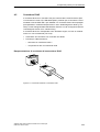
1
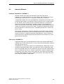
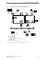
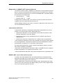
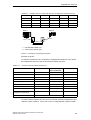
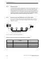
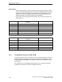
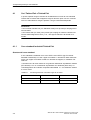
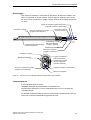
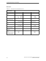
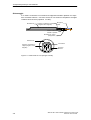
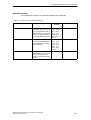
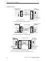
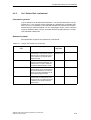
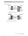
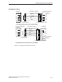
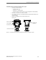
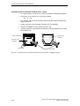
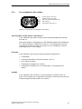
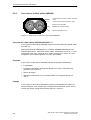
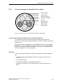
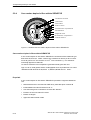
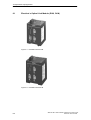
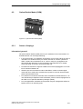
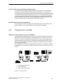
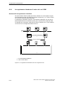
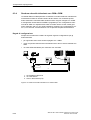
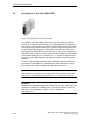
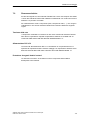
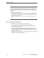
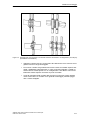
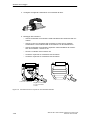
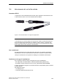
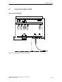
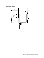
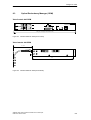
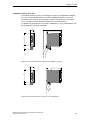
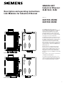
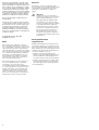
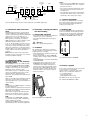
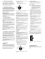
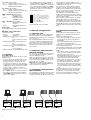
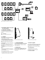
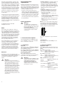
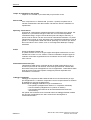
We have checked that the contents of the
technical publication agree with the hardware and software described. However, it is
not possible to rule out deviations completely, so we are unable to guarantee complete agreement. However, the details in the
technical publication are checked regularly.
Any corrections which prove necessary are
contained in subsequent editions. We are
grateful for suggestions for improvement.
We reserve the right to make technical
modifications.
Permission is not given for the circulation
or reproduction of this document, its use or
the passing on of its contents unless granted expressly. Contravention renders the
perpetrator liable for compensation for
damages. All rights reserved, in particular
in the case of patent grant or registration of
a utility or design.
Copyright © Siemens AG 1998
All Rights Reserved
Staff qualification
requirements
Qualified staff within the meaning of these
operating instructions or the warning notes
are persons familiar with setting up, assembling, starting up and operating this product
and who have appropriate qualifications to
cover their activities, such as:
– training or instruction/entitlement to
switch circuits and equipment/systems on
and off, earth them and identify them in
accordance with current safety standards;
– training or instruction in accordance with
current safety standards in looking after
and using appropriate safety equipment;
– first aid training.
Safety guidelines
v
Note
We would point out that the content of
these operating instructions is not part of,
nor is it intended to amend an earlier or existing agreement, permit or legal relationship. All obligations on Siemens arise from
the respective purchasing agreement which
also contains the full warranty conditions
which have sole applicability. These contractual warranty conditions are neither
extended nor restricted by comments in
these operating instructions.
We would furthermore point out that for
reasons of simplicity, these operating
instructions cannot describe every
conceivable problem associated with the
use of this equipment. Should you require
further information or should particular
problems occur which are not treated in
sufficient detail in the operating instructions, you can request the necessary information from your local Siemens office.
General
Electricity is used to operate this equipment. Comply in every detail with the safety
requirements specified in the operating
instructions regarding the voltages to
apply!
v
Warning!
If warning notes are ignored, it is
therefore possible for severe injuries
and/or material damage to occur.
Only appropriately qualified staff
should work on or near this equipment. Such staff must be thoroughly
acquainted with all the warnings
and maintenance measures contained in these operating instructions.
The proper and safe operation of
this equipment assumes proper
transport, appropriate storage and
assembly and careful operation and
maintenance.
2
Warning!
The ORM units are designed for
operation with safety extra-low voltage. Accordingly, only safety extralow voltages (SELV) to
IEC950/EN60950/VDE0805 may be
connected to the supply voltage
connections.
– Voltage supply: The voltage supply can
be connected to be redundant. Both
inputs are decoupled. There is no load
distribution. With redundant supply, the
power pack supplies the ORM alone with
the higher output voltage. The supply voltage is electrically isolated from the
housing.
– indicator contact: Contact interrupt
indicates the following by means of a
potential-free indicator contact (relay
contact, closed circuit):
– the failure of at least one of the two
supply voltages.
– a permanent fault in the ORM (internal
5 V DC voltage, supply voltage 1 or 2 not
in the permissible range).
– the faulty link status of at least one F/O
port.
– at least one port has auto partitioned.
– selft test error
Note: In case of the voltage supply being
routed without redundancy, the ORM indicates the failure of a supply voltage. You
can prevent this message by feeding in the
supply voltage through both inputs.
L1+
+24 V
F1
M
Fault
F2
L2+
1. Functional description
The Industrial Ethernet™ ORM has 2 F/O
ports (100 Mbit/s). A free end of an OSM
line is connected to each port.
1.1 INTERFACES
F/O ports
Two optical ports to 100BASE-FX (BFOC/2,5
(ST) sockets) enable to configure a redundant 100 Mbit/s backbone.
According to IEEE 802.3 standard 100BASEFX an ORM monitors the attached F/O lines
for open circuit conditions.
5-pin terminal block
The supply voltage and the indicator
contact are connected via a 5-pin terminal
block with screw locking mechanism.
v
Warning!
Industrial Ethernet™ ORMs are designed for operation with SELV. Only
safety extra-low voltages to
IEC950/EN60950/VDE0805 may
therefore be connected to the
supply voltage connections and to
the indicator contact.
+24 V
Fig. 1: Pin configuration of 5-pin terminal
block
V.24 Interface
This interface is intended solely for software updates.
1.2 DISPLAY ELEMENTS
Equipment status
These LEDs provide information about statuses which affect the function of the entire
ORMs.
L1 – Line 1 (green LED)
– lit:
– supply voltage 1 present
– lit not: – supply voltage 1 is less than 18 V,
– hardware fault in ORM
L2 – Line 2 (green LED)
– lit:
– supply voltage 2 present
– lit not: – supply voltage 2 is less than 18 V,
– hardware fault in ORM
CPU – System (Green/red LED)
– lit not:
– Initializing, hardware self
test
– lit red:
– Self test error
– flashes red (1 Hz):
– Loading software
– lit red with interruption:
– Writing to Flash EPROM
– lit yellow:
– The User Interface (V.24)
is occupied
– flashes yellow (0,5 Hz):
– The system is initialized
and runs fault-free.