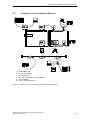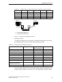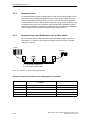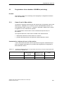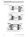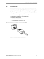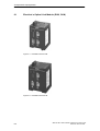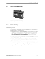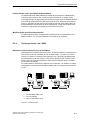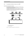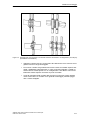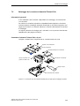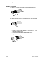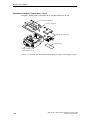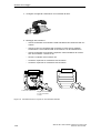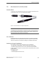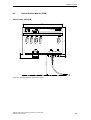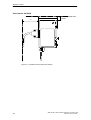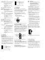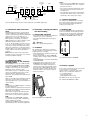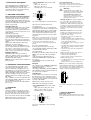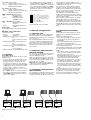
1
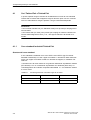
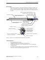
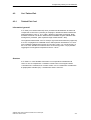
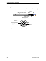
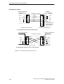
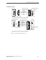
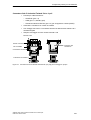
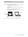
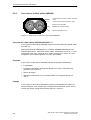
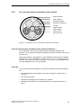
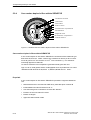
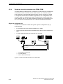
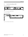
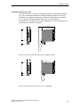
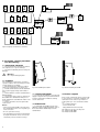
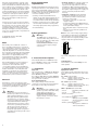
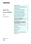
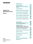
L1 – Line 1 (green LED)
– lit:
– supply voltage 1 present
– lit not: – supply voltage 1 is less than 18 V,
– hardware fault in OSM
L2 – Line 2 (green LED)
– lit:
– supply voltage 2 present
– lit not: – supply voltage 2 is less than 18 V,
– hardware fault in OSM
– the standby function can be enabled or
disabled with the switch Stby. State of
delivery: position 0 (Off), i.e. normal function. For redundant coupling of 10 MBit/s
network segments the OSM in the redundant link has to be run in the standby
mode (switch position 1).
0
FDX – Full duplex (Green LED)
– lit:
– full duplex mode
(10 MBit/s ports).
– lit not:
– half duplex mode
(10 MBit/s ports).
LA1
LA2
LA3
LA4
LA5
LA6
FDX
Stby
Stby – Standby (Green LED)
– lit:
– The standby function is
enabled.
– lit not:
– The standby function is
disabled.
Port Status
These LEDs display port-related information.
DA/STAT – Data, Link Status
(green/yellow LED)
– lit not:
– no valid link
– lit green:
– valid link
– blinking green (1 time in periodical interval)
– port is switched to standby
– blinking green (2 time in periodical interval)
– port is autopartitioned
– blinking green (3 time in periodical interval)
– port is disabled
– flashes yellow:– receiving data at this port
OSM
2. Network configurations
2.1 LINE STRUCTURE
The OSMs enable the setup of Industrial
Ethernet™ Backbones with 100 Mbit/s in
line structure. Cascading occurs via the F/O
ports (see Fig. 5).
The cascading depth and the total extension of the network are limited by the monitoring times of the communication links.
These times must be set so that they are
greater than the signal delay in the transmission link.
2.2 REDUNDANT RING STRUCTURE
WITH OSM AND ORM
The two ends of a backbone can be closed
to form a redundant optical ring with the
aid of an ORM (see Fig. 6).
With a reconfiguration time less than 0.5s,
up to 50 OSMs and an ORM can be operated in a redundant optical ring with a total
F/O length of up to 150km.
Note: With the redundant ring structure,
components other than OSMs/ORM may
not be included (e.g. switches).
2.3 REDUNDANT COUPLING OF NETWORK SEGMENTS
The standby port enables the linkage of two
Industrial Ethernet™ OSMs, one of which
operates in standby mode. By means of this
OSM
OSM
…
Abb. 5: Linienstruktur
4
Port 1
Port 2
The switch setting 0
suppresses message
Port 3
about link status
Port 4
via indicator contact
Port 5
Port 6
Full Duplex
Redundancy mode
Fig. 4: 8-pin DIP switch on OSM
1.5 CONTROLS
8-pin DIP switch
Using the 8-pin DIP switch on the top of the
OSM housing
– the message about the link status can be
suppressed by the indicator contact on a
port-by-port basis, e.g. if ports are not
connected or if a device is only switched
on from time to time. Using switches LA1
to LA6, the message about the link status
of ports 1 to 6 is suppressed. State on
delivery: switch position 1 (on), i.e. message not suppressed.
– the 10 MBit/s ports can be switched to the
full duplex or half duplex mode with the
switch FDX. State of delivery: position 0
(Off), i.e. half duplex.
OSM
1
OSM
operating mode, pairs of OSMs can be
employed for redundant switching of OSM
or OLM rings. (see Fig. 7).
The connection of two network segments
take place via two seperate paths with an
OSM each. The OSM for the redundant line
gets the redundancy function assigned by
the DIP switch setting standby.
The OSM in the redundant link and the
OSM in the main link report their operating
status via a connecting line (ITP XP line with
a max. length of 40m).
After the failure of the main line the redundant OSM enables the redundant line
immediately. If the main line is okay again,
the OSM in the main line informs the redundant OSM about this. The main line will be
enabled and the redundant line will be disabled.
2.4 COUPLING OF EXISTING NETWORKS
Each OSM can be linked with up to 4 Industrial Ethernet™ subnetworks via the ITP
ports.
The Ethernet planning rules
– Sum of the propagation equivalents and
line lengths in the worst case path less
than 4520m,
– Sum of the variability values in the worst
case path less than 50 bit times
must only – as previously – be contained in
each individual subnetwork.
The individual subnetworks can be mutually
decoupled by the switching function of the
OSM:
– The collision range of connected subnetworks ends at the OSM ports, the permitted total extension increases.
– Only valid data packets are passed on via
the OSM ports, disrupted subnetworks
cannot affect the other subnetworks.
– Data packets are only passed on to those
ports where the terminal is connected to
the destination address. The available
transmission capacity is increased since a
second network is no longer loaded with
the local data traffic from another sub-network.
Load decoupling and hence an increase in
network performance can be achieved by
the division of one network into subnetworks (segment formation) and the connection of these subnetworks to an OSM.
OSM