1
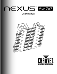
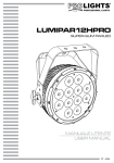
HALUROCK professional moving head ck ro MANUALE UTENTE USER MANUAL IT - EN Music & Lights S.r.l. si riserva ogni diritto di elaborazione in qualsiasi forma delle presenti istruzioni per l’uso. La riproduzione - anche parziale - per propri scopi commerciali è vietata. Al fine di migliorare la qualità dei prodotti, la Music&Lights S.r.l. si riserva la facoltà di modificare, in qualunque momento e senza preavviso, le specifiche menzionate nel presente manuale di istruzioni. Tutte le revisioni e gli aggiornamenti sono disponibili nella sezione 'Manuali' sul sito www.musiclights.it REV.006-11/14 HALUROCK INDICE Sicurezza Avvertenze generali Attenzioni e precauzioni per l’installazione Informazioni generali 4 4 5 1 Introduzione 1. 1 Descrizione 1. 2 Specifiche tecniche 1. 3 Elementi di comando e di collegamento 6 6 8 2 Installazione 2. 1 Montaggio 10 3 Funzioni e impostazioni 3. 1 Funzionamento 3. 2 Impostazione base 3. 3 Struttura menu 3. 4 Configurazioni canali DMX 3. 5 Indirizzamento DMX 3. 6 Collegamenti della linea DMX 3. 7 Costruzione del terminatore DMX 3. 8 Canali DMX 3. 9 Impostazioni dei motori 3. 10 Impostazioni protocollo 3. 11 Impostazioni ArtNet 3. 12 Impostazioni display 3. 13 Impostazioni di sistema 3. 14 Test sul dispositivo 3. 15 Funzione di reset 3. 16 Informazioni sul dispositivo 11 11 12 13 13 15 15 16 21 21 21 21 22 22 23 23 4 Manutenzione 4. 1 Manutenzione e pulizia del sistema ottico 4. 2 Sostituzione fusibile 4. 3 Risoluzione dei problemi 24 24 25 Certificato di garanzia Contenuto dell'imballo: 3 • • • • HALUROCK Cavo di alimentazione Supporti omega Manuale utente HALUROCK 4 ATTENZIONE! Prima di effettuare qualsiasi operazione con l’unità, leggere con attenzione questo manuale e conservarlo accuratamente per riferimenti futuri. Contiene informazioni importanti riguardo l’installazione, l’uso e la manutenzione dell’unità. SICUREZZA Avvertenze generali • I prodotti a cui questo manuale si riferisce sono conformi alle Direttive della Comunità Europea e pertanto recano la sigla . • Il dispositivo funziona con pericolosa tensione di rete 230V~. Non intervenire mai al suo interno al di fuori delle operazioni descritte nel presente manuale; esiste il pericolo di una scarica elettrica. • È obbligatorio effettuare il collegamento ad un impianto di alimentazione dotato di un’efficiente messa a terra (apparecchio di Classe I secondo norma EN 60598-1). Si raccomanda, inoltre, di proteggere le linee di alimentazione delle unità dai contatti indiretti e/o cortocircuiti verso massa tramite l’uso di interruttori differenziali opportunamente dimensionati. • Le operazioni di collegamento alla rete di distribuzione dell’energia elettrica devono essere effettuate da un installatore elettrico qualificato. Verificare che frequenza e tensione della rete corrispondono alla frequenza ed alla tensione per cui l’unità è predisposta, indicate sulla targhetta dei dati elettrici. • L’unità non per uso domestico, solo per uso professionale. • Evitare di utilizzare l’unità: - in luoghi soggetti a vibrazioni, o a possibili urti; - in luoghi a temperatura superiore ai 45°C. • Evitare che nell’unità penetrino liquidi infiammabili, acqua o oggetti metallici. • Non smontare e non apportare modifiche all’unità. • Tutti gli interventi devono essere sempre e solo effettuati da personale tecnico qualificato. Rivolgersi al più vicino centro di assistenza tecnica autorizzato. • Se si desidera eliminare il dispositivo definitivamente, consegnarlo per lo smaltimento ad un’istituzione locale per il riciclaggio. Attenzioni e precauzioni per l’installazione • Se il dispositivo dovesse trovarsi ad operare in condizioni differenti da quelle descritte nel presente manuale, potrebbero verificarsi dei danni; in tal caso la garanzia verrebbe a decadere. Inoltre, ogni altra operazione potrebbe provocare cortocircuiti, incendi, scosse elettriche, rotture etc. • Prima del montaggio controllare sempre le parti meccaniche ed elettriche dell’unità; non utilizzare il prodotto nel caso in cui siano danneggiate. Le parti danneggiate devono essere sostituite da un tecnico qualificato. • È assolutamente necessario proteggere l’unità per mezzo di una fune di sicurezza. Nell’eseguire qualsiasi intervento attenersi scrupolosamente a tutte le normative (in materia di sicurezza) vigenti nel paese di utilizzo. • Prima di iniziare qualsiasi operazione di manutenzione o pulizia sull’unità togliere la tensione dalla rete di alimentazione. • Installare l’unità in un luogo ben ventilato. • Assicurarsi che il dispositivo non sia esposto a temperature troppo elevate, umidità o polvere. • Mantenere i materiali infiammabili ad una distanza di sicurezza dall’unità. • I LED devono essere sostituiti se danneggiati o termicamente deformati. • Non guardare direttamente il fascio luminoso. Tenete presente che i veloci cambi di luce possono provocare attacchi d’epilessia presso persone fotosensibili o epilettiche. • Non rimuovere mai le etichette di avvertenza o informazione dall’unità. • In caso di sostituzione del fusibile, utilizzare esclusivamente un fusibile con caratteristiche identiche. HALUROCK 5 INFORMAZIONI GENERALI Spedizioni e reclami Le merci sono vendute “franco nostra sede” e viaggiano sempre a rischio e pericolo del distributore/cliente. Eventuali avarie e danni dovranno essere contestati al vettore. Ogni reclamo per imballi manomessi dovrà essere inoltrato entro 8 giorni dal ricevimento della merce. Garanzie e resi Il prodotto è coperto da garanzia in base alle vigenti normative. Sul sito www.musiclights.it è possibile consultare il testo integrale delle “Condizioni Generali di Garanzia”. Si prega, dopo l’acquisto, di procedere alla registrazione del prodotto sul sito www.musiclights.it. In alternativa il prodotto può essere registrato compilando e inviando il modulo riportato alla fine del manuale. A tutti gli effetti la validità della garanzia è avallata unicamente dalla presentazione del certificato di garanzia. Music & Lights constata tramite verifica sui resi la difettosità dichiarata, correlata all’appropriato utilizzo, e l’effettiva validità della garanzia; provvede quindi alla riparazione dei prodotti, declinando tuttavia ogni obbligo di risarcimento per danni diretti o indiretti eventualmente derivanti dalla difettosità. 6 HALUROCK - 1 - INTRODUZIONE 1.1 DESCRIZIONE HALUROCK è un proiettore altamente innovativo che ridefinisce il concetto tradizionale di testa mobile e matrici pixel, aggiungendo una nuova dimensione nei disegni luce di ogni palco. HALUROCK combina in un unico proiettore un output esplosivo, controllo pixel2pixel e movimenti, offrendo ad i light-designer uno strumento originale ed aperto alla creatività. Il gruppo ottico di HALUROCK sviluppa fasci di luce di 8°, sottili come spilli, in grado di incanalare luce in una proiezione dalla potenza senza precedenti ed altamente direttiva, creando grafiche ed effetti volumetrici nell'aria. HALUROCK ha una sorgente luminosa basata su 49 LED (matrice 7x7) CREE WarmWhite ad alta resa luminosa, con una temperatura colore di 2800K che richiama il classico effetto delle lampada alogene nei concerti rock. L'elettronica offre diverse funzioni avanzate come una gestione dimmer precisa e lineare, un'interfaccia display black-OLED ad alta risoluzione, ed il protocollo di control sia in DMX che Art-Net. Halurock impiega un avanzato sistema di dissipazione a liquido che consente una gestione ottimale della temperatura sulla scheda LED, aumentando l'output di emissione luminosa. 1.2 SPECIFICHE TECNICHE Sorgente luminosa e ottica • 49 (7x7) x 3W WarmWhite CREE LED ad alta resa luminosa • Color temperature: 2800K° • Angolo di proiezione: 6° • Angolo di campo: 8° • Luminosità: 30110 lux @3mt • Vita media sorgente LED: >50'000 h Dimmer/Strobo • Dimmer lineare 0-100% • Regolazione curva dimmer: 4 configurazioni selezionabili • Shutter indipendente ed effetti di dissolvenza a velocità variabile • Strobo: elettronico 1-20 flash/s Elettronica • Display ad alta risoluzione black-LED per accesso semplificato al menu di controllo, configurazione e assegnazione indirizzo • 5 configurazioni DMX disponibili: 13/16/55/62/65 canali per ampia flessibilità di controllo • Supporta protocolli sia DMX512 che ArtNet • Modalità Automatica: programmi automatici preimpostati con regolazione velocità • Modalità Master/Slave: per il controllo di più unità collegate in catena • Reset unità: tramite pannello di controllo o via DMX • Passaggio lineare “stepless” dei valori sui canali DMX • Frequenza dei diodi anti-flicker (>400Hz) Struttura e corpo mobile • Grado di isolamento: IP20 • Sistema di dissipazione a liquido che consente una gestione ottimale della temperatura sulla scheda LED, aumentando l'output di emissione lumnosa. • Raffreddamento ad aria filtrata forzata con ventole silenziate, non produce calore • Cavi di alimentazione (shuko) 1,5mt incluso HALUROCK 7 • • • • • Motori 3step per movimenti ultra-veloci e precisi Escursione: Pan = 540° (2,26 sec) Tilt = 270° (1,12 sec) Risoluzione Pan/Tilt: 8-bit o 16-bit Pan = 2,10° Pan Fine = 0,008° Tilt = 1,05° Tilt Fine = 0,004° Sospensione e fissaggio: qualsiasi posizione per mezzo di supporti omega (inclusi) con sistema di aggancio “quick lock” • Blocco meccanico Pan e Tilt per il trasporto e la manutenzione Alimentazione • Alimentazione: 100-240V 50/60Hz • Cablaggio IN/OUT alimentazione e segnale (DMX ed ArtNet) attraverso connessioni XLR3p-5p/ EtherCON /Powercon • Output alimentazione per connessione di più unità in serie: fino a 8 proiettori a 230V • Consumo ad emissione massima: 202W 471 Peso e dimensioni • Peso: 14 kg • Dimensioni (LxAxP): 379x471x288 mm 379 288 Disegno tecnico 9° Illuminance at a Distance 0m 3.0m 4.0m 5.0m 10.0m >40000lx 0.47m 24000lx 0.62m 16000lx 0.78m 4000lx 1.56m Lux Center Beam Angle: 9° Beam Width Diagramma di luminosità Fig.1 HALUROCK 8 1.3 ELEMENTI DI COMANDO E DI COLLEGAMENTO 1 2 B A ck ro 3 4 5 6 Up DMX Menu Enter NET Down Pannello A 7 8 9 11 13 15 Pannello B 10 12 14 16 17 Fig.2 HALUROCK 1. TESTA MOBILE 2. BRACCIO GIREVOLE 3. LEVA di blocco e sblocco testa mobile (movimento TILT) 4. LEVA di blocco e sblocco braccio girevole (movimento PAN) 5. MANIGLIA PER TRASPORTO 6. INDICATORE LED "Modalità DMX" 7. INDICATORE LED "Modalità ArtNet" 8. PANNELLO DI CONTROLLO con display LCD e 4 pulsanti per l'accesso e gestione delle diverse funzioni: -- Tasto MENU per selezionare il menu d'impostazione o tornare ad un livello del menu precedente. -- Tasto UP incrementa il valore visualizzato, oppure passa alla voce precedente di un menu. -- Tasto DOWN decrementa il valore visualizzato, oppure passa alla voce seguente di un menu. 9 -- Tasto ENTER conferma il valore visualizzato, oppure attiva la funzione visualizzata, oppure entra nel menu successivo 9. CONNETTORE RJ45 IN 10. CONNETTORE RJ45 OUT 11. DMX IN (XLR a 3 poli): 1 = massa, 2 = DMX -, 3 = DMX + 12. DMX OUT (XLR a 3 poli): 1= massa, 2 = DMX -, 3 = DMX + 13. DMX IN (XLR a 5 poli): 1 = massa, 2 = DMX -, 3 = DMX +, 4 N/C, 5 N/C 14. DMX OUT (XLR a 5 poli): 1= massa, 2 = DMX -, 3 = DMX +, 4 N/C, 5 N/C 15. PORTAFUSIBILE: sostituire un fusibile difettoso solo con uno dello stesso tipo (T3.15A/250V) 16. POWER IN ( PowerCON IN): per il collegamento ad una presa di rete (100-240V~/50-60Hz) tramite il cavo rete in dotazione. 17. POWER OUT (PowerCON OUT): collegamento per l'alimentazione all'unità successiva. HALUROCK 10 - 2 - INSTALLAZIONE 2.1 MONTAGGIO L’HALUROCK può essere collocato su un piano solido. Inoltre, grazie ai fori di fissaggio, l’unità può essere montata anche a testa in giù, su una traversa (fig.3). Per il fissaggio occorrono dei supporti robusti per il montaggio. Assicurarsi che l’unità sia saldamente fissata al fine di evitare vibrazioni e scivolamenti durante il funzionamento. L’area di collocazione deve avere una stabilità sufficiente e supportare almeno 10 volte il peso dell’unità. Inoltre assicurarsi di rispettare tutte le avvertenze in materia di sicurezza. È assolutamente necessario assicurare il proiettore contro la caduta utilizzando un cavo di sicurezza: in particolare collegare il cavo in un punto adatto in modo che la caduta del proiettore non possa superare i 20 cm. GANCIO ALISCAFF CAVO DI SICUREZZA SUPPORTI OMEGA Fig.3 HALUROCK 11 - 3 - FUNZIONI E IMPOSTAZIONI 3.1 FUNZIONAMENTO Inserire la spina del cavo di alimentazione in una presa di rete (200-240V~/50-60 Hz) per accendere l’HALUROCK solo dopo aver effettuato lo sblocco del movimento pan e tilt. La testa mobile e tutti i motori di comando si mettono in una precisa posizione di partenza. Poco dopo l’unità è pronta. Per spegnere l’HALUROCK, staccare la spina dalla presa di rete. Per maggiore comodità è consigliabile collegare l’unità con una presa comandata da un interruttore. 3.2 IMPOSTAZIONE BASE Il proiettore HALUROCK dispone di un display LCD e di 4 pulsanti per l’accesso alle funzioni del pannello di controllo e la loro gestione (fig.3). Up DMX Menu Enter NET Down MENU Per scorrere il menu principale o tornare ad una opzione del menu precedente UP Per scorrere attraverso le diverse funzioni in ordine ascendente o aumentare il valore della funzione stessa DOWN ENTER Per scorrere attraverso le diverse funzioni in ordine discendente o diminuire il valore della funzione stessa Per entrare nel menu selezionato o confermare il valore attuale della funzione o l'opzione all'interno di un menu Fig.4 - Funzione dei tasti HALUROCK 12 3.3 STRUTTURA MENU MENU 1 DMX Functions ð DMX Address DMX Channels ð ð 1 - 512 <13 CH> <16 CH> <55 CH> <62 CH> <65 CH> 2 ð Motor Setup Pan Inverse Tilt Inverse Motor Offset ð ð ð No- Yes No- Yes Pan Offset Tilt Offset 3 ð Display Setup Back Light ð On 10S 20S 30S Display Inverse ð No Yes Warn Cue ð Off On 4 ð System Setup Dimmer Mode ð Off Dimmer 1 Dimmer 2 Dimmer 3 Temperature Unit ð °C °F Fan Mode ð Auto Speed High Speed Factory Settings 5 Protocol Setup ð ð No - Yes ð <Static> Only DMX Only ArtNet ArtNet + DMX KlingNet + DMX 6 ð ArtNet Setup IP Mode <DHCP> <Manual> HALUROCK 13 Net Subnet Universe Start Channel 7 Test Setup ð Auto Test Manual Test ð ð ð ð ð ð 0 - 127 0 - 15 0 - 15 1 - 512 Auto Test... Pan Pan Fine Tilt Tilt Fine P/T Speed Dimmer Shutter 8 Reset Setup 9 Information ð ð ð ð ð ð ð ð ð 000 - 255 000 - 255 000 - 255 000 - 255 000 - 255 000 - 255 000 - 255 Auto Reset IP Address Device ID Temperature Fixture Time Software version ð ð ð ð ð 2.201.167.203 113944523 28°C 0 - 9999 A - CPU B - CPU C - CPU 3.4 CONFIGURAZIONI CANALI DMX L’HALUROCK dispone di 5 configurazioni dei canali DMX a cui si può accedere dal pannello di controllo. • Premere il tasto MENU e selezionare DMX Functions con il tasto UP/DOWN, quindi premere il tasto ENTER. • Premere il tasto UP/DOWN per selezionare DMX Channels, quindi premere il tasto ENTER. • Selezionare la configurazione dei canali DMX che si desidera (13CH - 16CH - 55CH - 62CH - 65CH) attraverso il tasto UP/DOWN. Le tabelle a pagina 16 indicano le modalità di funzionamento e i relativi valori DMX. Come interfaccia DMX, l’unità possiede dei contatti XLR a 3 e 5 poli. 3.5 INDIRIZZAMENTO DMX • Per poter entrare nella modalità DMX, premere il tasto MENU e selezionare DMX Functions con il tasto UP/ DOWN, quindi premere il tasto ENTER. • Premere il tasto UP/DOWN fino a quando sul display non appare DMX Address, quindi premere il tasto ENTER. • Selezionare il valore desiderato (001-512) attraverso il tasto UP/DOWN; tenere premuto per lo scorrimento veloce. • Al termine dell’impostazione il valore verrà salvato automaticamente. Per poter comandare l’HALUROCK con un’unità di comando luce, occorre impostare l’indirizzo di start DMX per il primo canale DMX. Se, per esempio, sull’unità di comando è previsto l’indirizzo 33 per coman- HALUROCK 14 dare la funzione del primo canale DMX, si deve impostare sull’HALUROCK l’indirizzo di start 33. Le altre funzioni del pannello saranno assegnate automaticamente agli indirizzi successivi. Segue un esempio con indirizzo 33 di start e una configurazione a 13, 16, 55, 62 e 65 canali DMX: Numero canali DMX Indirizzo di start (esempio) Indirizzo DMX occupati Prossimo indirizzo di start possibile per unità n°1 Prossimo indirizzo di start possibile per unità n°2 Prossimo indirizzo di start possibile per unità n°3 13 33 33-45 46 59 72 16 33 33-48 49 65 81 55 33 33-87 88 143 198 62 33 33-94 95 157 219 65 33 33-94 95 128 161 DMX Address: 33 DMX Address: 46 ck ro ck ro DMX Address: 59 ck ro DMX Address: 72 ck ro ............ DMX512 Controller Fig.5 - Esempio di configurazione a 13 canali DMX HALUROCK 15 3.6 COLLEGAMENTI DELLA LINEA DMX La connessione DMX è realizzata con connettori standard XLR. Utilizzare cavi schermati, 2 poli ritorti, con impedenza 120Ω e bassa capacità. Per il collegamento fare riferimento allo schema di connessione riportato di seguito: DMX - INPUT Spina XLR DMX - OUTPUT Presa XLR Pin1 : Massa - Schermo Pin2 : - Negativo Pin3 : + Positivo Pin4 : N/C Pin5 : N/C Fig.6 ATTENZIONE La parte schermata del cavo (calza) non deve mai essere collegata alla terra dell’impianto; ciò comporterebbe malfunzionamenti delle unità e dei controller. Per passaggi lunghi può essere necessario l’inserimento di un amplificatore DMX. In tal caso, è sconsigliato utilizzare nei collegamenti cavo bilanciato microfonico poiché non è in grado di trasmettere in modo affidabile i dati di controllo DMX. • Collegare l’uscita DMX del controller con l’ingresso DMX della prima unità; • Collegare, quindi, l’uscita DMX con l’ingresso DMX della successiva unità; l’uscita di quest’ultima con l’ingresso di quella successiva e via dicendo finchè tutte le unità sono collegate formando una catena. • Per installazioni in cui il cavo di segnale deve percorrere lunghe distanze è consigliato inserire sull’ultima unità una terminazione DMX. 3.7 COSTRUZIONE DEL TERMINATORE DMX La terminazione evita la probabilità che il segnale DMX 512, una volta raggiunta la fine della linea stessa venga riflesso indietro lungo il cavo, provocando, in certe condizioni e lunghezze, la sua sovrapposizione al segnale originale e la sua cancellazione. La terminazione deve essere effettuata, sull’ultima unità della catena, con connettori XLR a 3/5 pin, saldando una resistenza di 120Ω (minimo 1/4W) tra i terminali 2 e 3, così come indicato in figura. Esempio: connettore XLR a 3 pin Fig.7 HALUROCK 16 3.8 CANALI DMX 13 CANALI MODE 13 Ch FUNCTION DMX Value 1 PAN Pan movement 0° - 540° 000 - 255 2 PAN FINE 0 - 100% 000 - 255 3 TILT Tilt movement 0° - 220° 000 - 255 4 TILT FINE 0 - 100% 000 - 255 5 PAN/TILT SPEED Fast to slow 000 - 255 6 SPECIAL FUNCTION No function Reset all (hold 3 seconds) No function 000 - 199 200 - 209 210 - 255 7 DIMMER 0 - 100% 8 STROBE No Function Slow to fast 000 - 010 011 - 255 000-010 011-038 039-066 067-094 095-122 123-150 151-178 179-206 207-234 235-255 10 AUTO SPEED Slow to Fast 000 - 255 11 MOTOR SHOW No Function Motor Show 1 Motor Show 2 Motor Show 3 Motor Show 4 000-010 011-072 073-133 134-194 195-255 MOTOR SHOW SPEED Slow to Fast 000 - 255 12 13 FUNCTION DIMMER MODE Menu Setting dimmer mode dimmer mode off dimmer mode 1 dimmer mode 2 dimmer mode 3 DMX Value 000-051 052-101 102-152 153-203 204-255 16 CANALI MODE 16 Ch FUNCTION DMX Value 1 PAN Pan movement 0° - 540° 000 - 255 2 PAN FINE 0 - 100% 000 - 255 3 TILT Tilt movement 0° - 220° 000 - 255 4 TILT FINE 0 - 100% 000 - 255 5 PAN/TILT SPEED Fast to slow 000 - 255 6 SPECIAL FUNCTION No function Reset all (hold 3 seconds) No function 000 - 199 200 - 209 210 - 255 7 DIMMER 0 - 100% 000 - 255 8 STROBE No Function Slow to fast 000 - 010 011 - 255 9 FOREGROUND DIMMER 0~100% 000 - 255 10 BACKGROUND DIMMER 0~100% 000 - 255 11 ALPHANUMERIC No function Numeric characters 1 - 0 Alpha characters A - Z 000 - 000 001 - 127 128 - 255 000 - 255 AUTO PROGRAMS No Function Auto 1 Auto 2 Auto 3 Auto 4 Auto 5 Auto 6 Auto 7 Auto 8 Auto 0 9 MODE 13 Ch HALUROCK MODE 16 Ch 12 13 14 FUNCTION GOBO MAPS No Function Simple Cross Simple Box Square Imploder Square Exploder Diamond Imploder Diamond Exploder 2 Line Spinner Triangle Spinner Tri-Downer Tri-Upper Bowtie Spinner One-Liner Line Hop UP Line Hop DOWN Line Hop UP DOWN T-Spin Upside Down T-Spin Diamond Spoke Spin Line Hop LEFT Line Hop RIGHT Line Hop LEFT RIGHT Double Verticals Double Horizontals Diagonal Right Diagonal Left Moving Squares Clock GOB0 SPEED No function (stop) Gobo index No function (for later possible functions to add) Gobo speed (CW) Gobo Speed (CCW) ALPHANUMERIC ROTATION 0 degree 90 degree 180 degree 270 degree MOTOR SHOW No Function DMX Value 000-010 011-020 021-029 030-038 039-047 048-056 057-065 066-074 075-083 084-092 093-101 102-110 111-119 120-128 129-137 138-146 147-155 156-164 165-173 174-182 183-191 192-200 201-209 210-218 219-227 228-236 237-246 247-255 MODE 16 Ch 17 FUNCTION DMX Value 14 Motor Show 1 Motor Show 2 Motor Show 3 Motor Show 4 011-072 073-133 134-194 195-255 15 MOTOR SHOW SPEED Slow to Fast 000 - 255 16 DIMMER MODE Menu Setting dimmer mode dimmer mode off dimmer mode 1 dimmer mode 2 dimmer mode 3 000-051 052-101 102-152 153-203 204-255 55 CANALI MODE 55 Ch FUNCTION DMX Value 1 PAN Pan movement 0° - 540° 000 - 255 2 PAN FINE 0 - 100% 000 - 255 3 TILT Tilt movement 0° - 220° 000 - 255 4 TILT FINE 0 - 100% 000 - 255 5 PAN/TILT SPEED Fast to slow 000 - 255 000-010 011-100 6 101-149 150-202 203-255 SPECIAL FUNCTION No function Reset all (hold 3 seconds) No function 000 - 199 200 - 209 210 - 255 7 WHITE 1 0 - 100% 000 - 255 8 WHITE 2 0 - 100% 000 - 255 9 WHITE 3 0 - 100% 000 - 255 ... ... 000-063 064-127 128-191 192-255 000-010 ... HALUROCK 18 MODE 55 Ch FUNCTION DMX Value MODE 62 Ch ... ... ... 53 WHITE 47 0 - 100% 000 - 255 54 WHITE 48 0 - 100% 000 - 255 55 WHITE 49 0 - 100% 000 - 255 56 AUTO PROGRAMS No Function Auto 1 Auto 2 Auto 3 Auto 4 Auto 5 Auto 6 Auto 7 Auto 8 Auto 0 000-010 011-038 039-066 067-094 095-122 123-150 151-178 179-206 207-234 235-255 57 AUTO SPEED Slow to Fast 000 - 255 58 DIMMER 0 - 100% 000 - 255 59 STROBE No Function Slow to fast 000 - 010 011 - 255 60 MOTOR SHOW No Function Motor Show 1 Motor Show 2 Motor Show 3 Motor Show 4 000-010 011-072 073-133 134-194 195-255 61 MOTOR SHOW SPEED Slow to Fast 62 DIMMER MODE Menu Setting dimmer mode dimmer mode off dimmer mode 1 dimmer mode 2 dimmer mode 3 ... ... 53 WHITE 47 0 - 100% 000 - 255 54 WHITE 48 0 - 100% 000 - 255 55 WHITE 49 0 - 100% 000 - 255 62 CANALI MODE 62 Ch FUNCTION DMX Value 1 PAN Pan movement 0° - 540° 000 - 255 2 PAN FINE 0 - 100% 000 - 255 3 TILT Tilt movement 0° - 220° 000 - 255 4 TILT FINE 0 - 100% 000 - 255 5 PAN/TILT SPEED Fast to slow 000 - 255 6 SPECIAL FUNCTION No function Reset all (hold 3 seconds) No function 000 - 199 200 - 209 210 - 255 7 WHITE 1 0 - 100% 000 - 255 8 WHITE 2 0 - 100% 000 - 255 9 WHITE 3 0 - 100% 000 - 255 ... ... ... ... ... ... FUNCTION DMX Value ... 000 - 255 000-051 052-101 102-152 153-203 204-255 HALUROCK 19 65 CANALI MODE 65 Ch FUNCTION DMX Value 1 PAN Pan movement 0° - 540° 000 - 255 2 PAN FINE 0 - 100% 000 - 255 3 TILT Tilt movement 0° - 220° 000 - 255 4 TILT FINE 0 - 100% 000 - 255 5 PAN/TILT SPEED Fast to slow 000 - 255 6 SPECIAL FUNCTION No function Reset all (hold 3 seconds) No function 000 - 199 200 - 209 210 - 255 7 WHITE 1 0 - 100% 000 - 255 8 WHITE 2 0 - 100% 000 - 255 9 WHITE 3 0 - 100% 000 - 255 ... ... ... ... ... ... ... ... ... 53 WHITE 47 0 - 100% 000 - 255 54 WHITE 48 0 - 100% 000 - 255 55 WHITE 49 0 - 100% 000 - 255 56 FOREGROUND DIMMER 0~100% 000 - 255 57 BACKGROUND DIMMER 0~100% 000 - 255 58 ALPHANUMERIC No function 000 - 000 MODE 65 Ch FUNCTION DMX Value 58 Numeric characters 1 - 0 Alpha characters A - Z 001 - 127 128 - 255 59 GOBO MAPS No Function Simple Cross Simple Box Square Imploder Square Exploder Diamond Imploder Diamond Exploder 2 Line Spinner Triangle Spinner Tri-Downer Tri-Upper Bowtie Spinner One-Liner Line Hop UP Line Hop DOWN Line Hop UP DOWN T-Spin Upside Down T-Spin Diamond Spoke Spin Line Hop LEFT Line Hop RIGHT Line Hop LEFT RIGHT Double Verticals Double Horizontals Diagonal Right Diagonal Left Moving Squares Clock 000-010 011-020 021-029 030-038 039-047 048-056 057-065 066-074 075-083 084-092 093-101 102-110 111-119 120-128 129-137 138-146 147-155 156-164 165-173 174-182 183-191 192-200 201-209 210-218 219-227 228-236 237-246 247-255 GOB0 SPEED No function (stop) Gobo index No function (for later possible functions to add) Gobo speed (CW) Gobo Speed (CCW) 000-010 011-100 101-149 150-202 203-255 ALPHANUMERIC ROTATION 0 degree 90 degree 180 degree 270 degree 000-063 064-127 128-191 192-255 60 HALUROCK 20 MODE 65 Ch FUNCTION DMX Value 61 DIMMER 0 - 100% 000 - 255 62 STROBE No Function Slow to fast 000 - 010 011 - 255 63 MOTOR SHOW No Function Motor Show 1 Motor Show 2 Motor Show 3 Motor Show 4 000-010 011-072 073-133 134-194 195-255 64 MOTOR SHOW SPEED Slow to Fast 65 DIMMER MODE Menu Setting dimmer mode dimmer mode off dimmer mode 1 dimmer mode 2 dimmer mode 3 000 - 255 000-051 052-101 102-152 153-203 204-255 1 2 3 4 5 6 7 8 9 10 11 12 13 14 15 16 17 18 19 20 21 22 23 24 25 26 27 28 29 30 31 32 33 34 35 36 37 38 39 40 41 42 43 44 45 46 47 48 49 HALUROCK 21 3.9 IMPOSTAZIONI MOTORI • Dalla schermata iniziale, premere il tasto MENU e selezionare Motor Setup con il tasto UP/DOWN, quindi premere il tasto ENTER. • Selezionare l’opzione proposta con il tasto UP/DOWN e premere il tasto ENTER per confermare l’impostazione. -- Pan Inverse - Rotazione in senso opposto della testa mobile. No Disattiva la funzione (impostazione normale), Yes Attiva la funzione (Pan inverse). -- Tilt Inverse - Inclinazione in senso opposto della testa mobile. No Disattiva la funzione (impostazione normale), Yes Attiva la funzione (Tilt inverse). -- Motor Offset - Permette di impostare un offset per i motori di pan/tilt. Pan Offset imposta un offset per il motore del pan, Tilt Offset imposta un offset per il motore del tilt. • Premere il tasto MENU per tornare indietro o attendere qualche secondo per uscire dal menu di impostazione. 3.10 IMPOSTAZIONI PROTOCOLLO Per impostare il protocollo di comunicazione da utilizzare per l’unità far riferimento alla seguente sezione del menu. • Dalla schermata iniziale, premere il tasto MENU e selezionare Protocol Setup con il tasto UP/DOWN, quindi premere il tasto ENTER. • Selezionare l’opzione proposta con il tasto UP/DOWN e premere il tasto ENTER per confermare l’impostazione. -- Only DMX - Selezionando tale opzione si imposta il protocollo di comunicazione DMX, quindi vengono abilitati gli ingressi e le uscite DMX e viene disabilitato l’ingresso e l’uscita ArtNet. -- Only ArtNet - Selezionando tale opzione si imposta il protocollo di comunicazione ArtNet, quindi viene abilitato l’ingresso e l’uscita ArtNet e vengono disabilitati gli ingressi e le uscite DMX. -- ArtNet + DMX - Selezionando tale opzione si impostano come protocolli di comunicazione sia quello DMX che quello ArtNet, quindi tutti gli ingressi e le uscite vengono abilitate. -- KlingNet + DMX - Selezionando tale opzione si impostano come protocolli di comunicazione sia quello DMX che quello KlingNet, quindi tutti gli ingressi e le uscite vengono abilitate. • Premere il tasto MENU per tornare indietro o attendere qualche secondo per uscire dal menu di impostazione. 3.11 IMPOSTAZIONI ARTNET Per le impostazioni ArtNet da attribuire all’unità far riferimento alla seguente sezione del menu. • Dalla schermata iniziale, premere il tasto MENU e selezionare ArtNet Setup con il tasto UP/DOWN, quindi premere il tasto ENTER. • Selezionare con i tasti UP/DOWN una delle seguenti impostazioni: IP Mode, Net, Subnet, Universe, Start Channel. • Premere il tasto ENTER per confermare la scelta ed entrare nel sub menu. • Impostrare mediante i tasti UP/DOWN il valore desiderato relativo alla funzione scelta. Quindi premere il tasto ENTER. • Premere il tasto MENU per tornare indietro o attendere alcuni secondi per uscire dal menu di impostazione. 3.12 IMPOSTAZIONI DISPLAY • Dalla schermata iniziale, premere il tasto MENU e selezionare Display Setup con il tasto UP/DOWN, quindi premere il tasto ENTER. • Selezionare l’opzione proposta con il tasto UP/DOWN e premere il tasto ENTER per confermare l’impostazione. 22 HALUROCK -- Back Light - Retroilluminazione display. Usare i tasti UP/DOWN per selezionare l’impostazione display sempre acceso On oppure Off per selezionare l’impostazione display spento un minuto dopo l’uscita dal menu. -- Display Inverse - Visualizzazione inversa del display. Selezionare Yes oppure No a seconda che si voglia attivare o disattivare la funzione di inversione del display. -- Warn Cue - Avviso di errore. Usare i tasti direzionali per selezionare No oppure Yes a seconda che si voglia o meno che il display mostri avvisi di errore. • Premere il tasto MENU per tornare indietro o attendere qualche secondo per uscire dal menu di impostazione. 3.13 IMPOSTAZIONI DI SISTEMA • Dalla schermata iniziale, premere il tasto MENU e selezionare System Setup con il tasto UP/DOWN, quindi premere il tasto ENTER. • Selezionare l’opzione proposta con il tasto UP/DOWN e premere il tasto ENTER per confermare l’impostazione. -- Dimmer Mode - Funzione Dimmer. Selezionare la funzione Dimmer Mode, per entrare nella modalità dimmer e scegliere e simulare diverse curve dimming. In particolare, quando è impostato su: • Off - L’aumento dell’intensità luminosa è lineare. • Dimmer 1 - Il controllo dell’intensità luminosa è più fine a livelli bassi e grossolana a livelli alti. • Dimmer 2 - Il controllo dell’intensità luminosa è più fine a livelli alti e grossolana a livelli bassi. • Dimmer 3 - Il controllo dell’intensità luminosa è più fine a livelli bassi e alti, e grossolana a livelli medi. -- Temperature Unit - Scala di temperatura. Questa funzione permette di scegliere la scala di temperatura tra °C e °F. -- Fan Mode - Velocità di rotazione ventole. E’ possibile scegliere la velocità di rotazione delle ventole tra: lento veloce High Speed e automatico Auto Speed. -- Factory Settings - Reset di fabbrica. Selezionare la funzione Factory Settings e poi Yes per ripristinare tutti i valori all’impostazione originale di fabbrica. • Premere il tasto MENU per tornare indietro o attendere qualche secondo per uscire dal menu di impostazione. 3.14 TEST SUL DISPOSITIVO Auto Test Permette di verificare il corretto funzionamento dell’unità. Per avviare il test procedere nel seguente modo: • Dal menu iniziale selezionare Test Setup con il tasto UP/DOWN, quindi premere il tasto ENTER. • Premere il tasto UP/DOWN per selezionare Auto Test. Confermare l’impostazione con il tasto ENTER. • Per confermare e dare l’avvio al test automatico premere il tasto ENTER. Manual Test Permette di eseguire tramite pannello comandi delle regolazioni sugli effetti per ottenere una perfetta uniformità tra i proiettori. • Dal menu iniziale selezionare Test Setup con il tasto UP/DOWN, quindi premere il tasto ENTER. • Premere il tasto UP/DOWN per selezionare Manual Test. Confermare l’impostazione con il tasto ENTER. • Selezionare l’effetto sul quale si desidera eseguire la regolazione (Pan, Pan Fine, Tilt, Tilt Fine, P/T Speed, Dimmer, Shutter) e confermare premendo il tasto ENTER. • Eseguire la calibratura dell’effetto attraverso i tasti direzionali impostando un valore tra 0 - 255 e premere il tasto ENTER per confermare l’impostazione. HALUROCK 23 • Premere il tasto MENU per tornare indietro o attendere qualche secondo per uscire dal menu di impostazione. 3.15 FUNZIONE DI RESET • Dal menu iniziale selezionare Reset Setup con il tasto UP/DOWN, quindi premere il tasto ENTER per entrare nella sezione Auto Reset. • Per confermare e dare l’avvio al test automatico premere il tasto ENTER. • Premere il tasto MENU per tornare indietro o attendere qualche secondo per uscire dal menu di impostazione. 3.16 INFORMAZIONI SUL DISPOSITIVO • Dalla schermata iniziale, premere il tasto MENU e selezionare Information con il tasto UP/DOWN, quindi premere il tasto ENTER. • Selezionare l’opzione proposta con il tasto UP/DOWN e premere il tasto ENTER per confermare l’impostazione. -- IP Address - Attraverso la funzione IP Address è possibile visualizzare sul display l'indirizzo IP dell'unità. -- Device ID - Attraverso la funzione Device ID è possibile visualizzare sul display l’ID dell’unità. -- Temperature - Attraverso la funzione Temperature è possibile visualizzare sul display la temperatura relativa al dispositivo in °C. Quando la temperatura è sotto i 60°C il dispositivo funziona normalmente, quando la temperatura è tra i 65°C e 75°C il dispositivo riduce la potenza e quando si raggiungono i 75°C o superiore, il display LED sarà spento. -- Fixture Time - Attraverso la funzione Fixture Time è possibile visualizzare sul display il tempo di funzionamento del proiettore. -- Software Version - Attraverso la funzione Software Version è possibile visualizzare sul display la versione del software installata. • Premere il tasto MENU per tornare indietro o attendere qualche secondo per uscire dal menu di impostazione. 24 HALUROCK - 4 - MANUTENZIONE 4.1 MANUTENZIONE E PULIZIA DEL SISTEMA OTTICO • Durante gli interventi, assicurarsi che l’area sotto il luogo di installazione sia libera da personale non qualificato. • Spegnere l’unità, scollegare il cavo di alimentazione ed aspettare finché l’unità non si sia raffreddata. • Tutte le viti utilizzate per l’installazione dell’unità e le sue parti dovrebbero essere assicurate saldamente e non dovrebbero essere corrose. • Alloggiamenti, elementi di fissaggio e di installazione (soffitto, truss, sospensioni) dovrebbero essere totalmente esenti da qualsiasi deformazione. • Quando una lente ottica è visibilmente danneggiata a causa di rotture o graffi profondi, deve essere sostituita. • I cavi di alimentazione devono essere in condizione impeccabile e dovrebbero essere sostituiti immediatamente nel momento in cui anche un piccolo problema viene rilevato. • Al fine di proteggere l’unità da surriscaldamento, le ventole di raffreddamento (e nel caso) le aperture di ventilazione, devono essere pulite mensilmente. Per mantenere funzionalità e rendimento ottimali per lungo tempo è indispensabile effettuare una pulizia periodica delle parti soggette all’accumulo di polveri e grassi. La frequenza con la quale effettuare le operazioni sotto indicate dipende da diversi fattori, quali la quantità di movimenti degli effetti e la qualità dell’ambiente di lavoro (umidità dell’aria, presenza di polvere, salsedine, ecc.). Per rimuovere lo sporco dal riflettore, dalle lenti e dai filtri usare un panno morbido inumidito di un qualsiasi liquido detergente per la pulizia del vetro. Annualmente si consiglia di sottoporre il proiettore a personale tecnico qualificato per una manutenzione straordinaria consistente almeno nelle seguenti operazioni: -- Pulizia generale delle parti interne. -- Ripristino della lubrificazione di tutte le parti soggette ad attrito tramite l’utilizzo di lubrificanti appropriati. -- Controllo visivo generale di componenti interni, cablaggio, parti meccaniche, ecc. -- Controlli elettrici, fotometrici e funzionali; eventuali riparazioni. Attenzione: consigliamo che la pulizia interna sia eseguita da personale qualificato! 4.2 SOSTITUZIONE FUSIBILE 1. Assicurarsi di scollegare il cavo di alimentazione del proiettore prima di sostituire un fusibile bruciato. 2. Con un cacciavite, rimuovere il portafusibile dalla sua sede e il fusibile bruciato dal suo supporto; sostituire il fusibile con uno identico per tipologia e valore (T3.15A/250V). 3. Inserire il portafusibile al suo posto e ricollegare l’alimentazione. Fig.8 HALUROCK 25 4.3 RISOLUZIONE DEI PROBLEMI Anomalie Possibili cause Il proiettore non illumina • • • • • Bassa intensità di luce generale Il proiettore non è alimentato Il proiettore non risponde al DMX Controlli e rimedi • • • • • • • Mancanza di alimentazione di rete Dimmer impostato a 0 Tutti i colori impostati a 0 LED difettoso/i Scheda LED difettosa Lenti sporche Lente disallineata • • Verificare la presenza della tensione alimentazione Incrementare i valori del canale dimmer Incrementare i valori dei canali colori Sostituire scheda LED Sostituire scheda LED Pulire il dispositivo regolarmente Installare il gruppo ottico correttamente • • • Mancanza di alimentazione di rete Cavo di alimentazione danneggiato Alimentatore interno difettoso • • • Verificare la presenza della tensione alimentazione Controllare il cavo di alimentazione Sostituire l'alimentatore interno • Indirizzamento DMX errato • • • Cavo di segnale DMX difettoso Rimbalzo segnale DMX • • Controllare il pannello di controllo e l'indirizzamento delle unità Controllare il cavo di segnale DMX Installare una terminazione DMX come suggerito Rivolgersi a un centro di assistenza tecnico autorizzato nel caso in cui il problema non sia riportato in tabella. All rights reserved by Music & Lights S.r.l. No part of this instruction manual may be reproduced in any form or by any means for any commercial use. In order to improve the quality of products, Music&Lights S.r.l. reserves the right to modify the characteristics stated in this instruction manual at any time and without prior notice. All revisions and updates are available in the ‘manuals’ section on site www.musiclights.it HALUROCK TABLE OF CONTENTS Safety General instructions Warnings and installation precautions General information 2 2 3 1 Introduction 1. 1 Description 1. 2 Technical specifications 1. 3 Operating elements and connections 4 4 6 2 Installation 2. 1 Mounting 8 3 Functions and settings 3. 1 Operation 3. 2 Basic 3. 3 Menu structure 3. 4 DMX configuration 3. 5 DMX addressing 3. 6 Connection of the DMX line 3. 7 Construction of the DMX termination 3. 8 DMX control 3. 9 Motor setting 3. 10 Protocol setting 3. 11 ArtNet setting 3. 12 Display setting 3. 13 System setting 3. 14 Fixture test 3. 15 Reset function 3. 16 Fixture information 9 9 10 11 11 13 13 14 19 19 19 19 20 20 21 21 4 Maintenance 4. 1 Maintenance and cleaning the unit 4. 2 Fuse replacement 4. 3 Trouble shooting 22 22 23 Warranty Packing content 1 • • • • HALUROCK Power cable Omega holder User manual HALUROCK 2 WARNING! Before carrying out any operations with the unit, carefully read this instruction manual and keep it with cure for future reference. It contains important information about the installation, usage and maintenance of the unit. SAFETY General instruction • The products referred to in this manual conform to the European Community Directives and are therefore marked with . • The unit is supplied with hazardous network voltage (230V~). Leave servicing to skilled personnel only. Never make any modifications on the unit not described in this instruction manual, otherwise you will risk an electric shock. • Connection must be made to a power supply system fitted with efficient earthing (Class I appliance according to standard EN 60598-1). It is, moreover, recommended to protect the supply lines of the units from indirect contact and/or shorting to earth by using appropriately sized residual current devices. • The connection to the main network of electric distribution must be carried out by a qualified electrical installer. Check that the main frequency and voltage correspond to those for which the unit is designed as given on the electrical data label. • This unit is not for home use, only professional applications. • Never use the fixture under the following conditions: - in places subject to vibrations or bumps; - in places with an ambient temperature of over 45°C. • Make certain that no inflammable liquids, water or metal objects enter the fixture. • Do not dismantle or modify the fixture. • All work must always be carried out by qualified technical personnel. Contact the nearest sales point for an inspection or contact the manufacturer directly. • If the unit is to be put out of operation definitively, take it to a local recycling plant for a disposal which is not harmful to the environment. Warnings and installation precautions • If this device will be operated in any way different to the one described in this manual, it may suffer damage and the guarantee becomes void. Furthermore, any other operation may lead to dangers like short circuit, burns, electric shock, etc. • Always inspect the mechanical and electrical parts of the unit before fitting to check they are not damaged. Do not operate the product if you see damage. If the part is damaged, it has to be replaced by a qualified technician. • When hanging the product, always use a safety cable. When carrying out any work, always comply scrupulously with all the regulations (particularly regarding safety) currently in force in the country in which the fixture’s being used. • Before starting any maintenance work or cleaning the fixture, cut off power from the main supply. • Install the fixture in a well ventilated place. • Make sure that the device is not exposed to extreme heat, moisture or dust. • Keep any inflammable material at a safe distance from the fixture. • The lamp (LED) shall be changed if it has become damaged or thermally deformed. • Never look directly at the light beam. Please note that fast changes in lighting, e. g. flashing light, may trigger epileptic seizures in photosensitive persons or persons with epilepsy. • Never remove warning or informative labels from the unit. • For replacement use fuses of same type and rating only. HALUROCK 3 GENERAL INFORMATION Shipments and claims The goods are sold “ex works” and always travel at the risk and danger of the distributor. Eventual damage will have to be claimed to the freight forwarder. Any claim for broken packs will have to be forwarded within 8 days from the reception of the goods. Warranty and returns The guarantee covers the fixture in compliance with existing regulations. You can find the full version of the “General Guarantee Conditions” on our web site www.musiclights.it. Please remember to register the piece of equipment soon after you purchase it, logging on www.musiclights.it. The product can be also registered filling in and sending the form available on your guarantee certificate. For all purposes, the validity of the guarantee is endorsed solely on presentation of the guarantee certificate. Music & Lights will verify the validity of the claim through examination of the defect in relation to proper use and the actual validity of the guarantee. Music & Lights will eventually provide replacement or repair of the products declining, however, any obligation of compensation for direct or indirect damage resulting from faultiness. 4 HALUROCK - 1 - INTRODUCTION 1.1 DESCRIPTION HALUROCK is a highly innovative projector that redefines the traditional concept of moving head and pixel matrix, adding a new dimension in the light design of every stage. HALUROCK combines in a single projector an explosive output, pixel2pixel control and movements, providing a new and original tool to the light-designers to freely open the creativity. The optical group of HALUROCK develops light beams of 8 °, thin as pins, capable of channeling light in a projection with unprecedent brightness and highly directive, creating volumetric effects and graphics in the air. The HALUROCK light source is based on 49 (7x7 matrix) high-lumen CREE Warm White LEDs, with a 2800K° color temperature which recalls the classic effect of the halogen lamp in rock concerts.The electronics offers several advanced features such as a precise and linear management of dimmer, high resolution black-OLED display, and both DMX and Art-Net control protocol on board. Halurock employs the new cutting-edge liquid cooling system, which allows a better temperature management of LED board to deliver higher output. 1.2 TECHNICAL SPECIFICATIONS Light source and optics • 49 (7x7) x 3W CREE high-efficiency WarmWhite LEDs • Color temperature: 2800K° • Beam angle: 6° • Field angle: 8° • Brightness: 30110 lux @3mt • LEDs average life span: >50’000 h Dimmer/Shutter/Strobe/Colors • 0-100% linear dimmer • 4 different dimming curves available • Independent shutter and fading effects with adjustable speed • Strobe: Electronic, 1-20 flash per second Electronics • High resolution black-OLED display for simplified access to control menu, configuration and DMX addressing • 5 DMX configurations available: 13/16/55/62/65 channels for full flexibility and control • Both DMX and Art-Net control protocol supported • Auto mode: built-in programs with execution speed adjustment • Master/Slave mode: for synchronized operation of more units linked in a chain • Unit reset: through control panel or via DMX • Linear and “stepless” transition between DMX values • Flicker-free operations (>400Hz) Structure and moving body • Internal protection: IP20 • New cutting-edge liquid cooling system, which allows a better temperature management of LED board to deliver higher output • Cooling: forced ventilation with low-noise fans, no heat generation • Power cable (shuko 1,5mt) included HALUROCK • • • • • • 5 3phase motor for precise and ultra-fast moves Motion Angle: Pan = 540° (2,26 sec) Tilt = 270° (1,12 sec) Pan/Tilt resolution: 8-bit or 16-bit: Pan = 2,10° Pan Fine = 0,008° Tilt = 1,05° Tilt Fine = 0,004° Suspension and fixing: any possible working position through “quick lock” omega brackets (included) Pan and Tilt locking for transportation and maintenance Power supply • Power supply: 100-240V 50/60Hz • IN/OUT power wiring and signal (DMX and ArtNet) through connections XLR3p-5p/ EtherCON /Powercon • Power output allowing up to 8 units to be connected on a single power line (at 230V) • Max power consumption: 202W 471 Weight and dimensions • Weight: 14 kg • Dimensions (WxHxD): 379x471x288 mm 379 288 Technical drawing 9° Illuminance at a Distance 0m 3.0m 4.0m 5.0m 10.0m >40000lx 0.47m 24000lx 0.62m 16000lx 0.78m 4000lx 1.56m Lux Center Beam Angle: 9° Beam Width Photometric data Fig.1 HALUROCK 6 1.3 OPERATING ELEMENTS AND CONNECTIONS 1 2 B A ck ro 3 4 5 6 Up DMX Menu Enter NET Down View A 7 8 9 11 13 15 View B 10 12 14 16 17 Fig.2 HALUROCK 1. MOVING HEAD 2. ROTARY ARM 3. LEVEL for locking and unlocking the moving head (TILT movement) 4. LEVEL for locking and unlocking the folding arms (PAN movement) 5. HANDLE 6. LED INDICATOR "DMX mode" 7. LED INDICATOR "ArtNet mode" 8. CONTROL PANEL with LCD display and 4 button used to access the control panel functions and manage them: -- MENU button: scroll through the main menu or exits from the current submenu. -- UP button: increases the value displayed or passes to the next item in a menu. -- DOWN button: decreases the value displayed or passes to the next item in the menu. 7 -- ENTER button: enter the currently selected menu or confirm the current function value. 9. RJ45 IN CONNECTOR 10. RJ45 OUT CONNECTOR 11. DMX IN (3-pole XLR): 1 = ground, 2 = DMX -, 3 = DMX + 12. DMX OUT ( 3-pole XLR): 1 = ground, 2 = DMX -, 3 = DMX + 13. DMX IN (5-pole XLR): 1 = ground, 2 = DMX-, 3 = DMX+, 4 N/C, 5 N/C 14. DMX OUT (5-pole XLR): 1 = ground, 2 = DMX-, 3 = DMX+, 4 N/C, 5 N/C 15. MAIN FUSE HOLDER: replace a burnt-out fuse by one of the same type only (T3.15A/250V). 16. POWER IN (PowerCON IN): for connection to a socket (100-240V~/50-60Hz) via the supplied mains cable. 17. POWER OUT (PowerCON OUT): power output for connection of multiple units in series. HALUROCK 8 - 2 - INSTALLATION 2.1 MOUNTING The HALUROCK may be set up on a solid and even surface. By means of the fixing facilities of the baseplate, the unit can also be mounted upside down to a cross arm (fig.3). For fixing, stable mounting clips are required. Always ensure that the unit is firmly fixed to avoid vibration and slipping while operating. The mounting place must be of sufficient stability and be able to support a weight of 10 times of the unit’s weight. When carrying out any installation, always comply scrupulously with all the regulations (particularly regarding safety) currently in force in the country in which the fixture’s being used. Always additionally secure the projector with the safety rope from falling down. For this purpose, fasten the safety rope at a suitable position so that the maximum fall of the projector will be 20 cm. CLAMP SAFETY CABLE OMEGA BRACKETS Fig.3 HALUROCK 9 - 3 - FUNCTIONS AND SETTINGS 3.1 OPERATION Unlock the PAN and TILT mechanism. Connect the supplied main cable to a socket (230V~/50-60Hz). Shortly after that the HALUROCK is ready for operation. To switch off, disconnect the mains plug from the socket. For a more convenient operation it is recommended to connect the unit to a socket which can be switched on and off via a light switch. 3.2 BASIC The HALUROCK has a LCD display and 4 button used to access the control panel functions and manage them (fig.4). Up DMX Menu Enter NET Down MENU Used to access the menu or to return a previous menu option UP Navigates upwards through the menu list and increases the numeric value when in a function DOWN ENTER Navigates downwards through the menu list and decreases the numeric value when in a function Used to select and store the current menu or confirm the current function value or option within a menu Fig.4 - Functions of the buttons HALUROCK 10 3.3 MENU STRUCTURE MENU 1 DMX Functions ð DMX Address DMX Channels ð ð 1 - 512 <13 CH> <16 CH> <55 CH> <62 CH> <65 CH> 2 ð Motor Setup Pan Inverse Tilt Inverse Motor Offset ð ð ð No- Yes No- Yes Pan Offset Tilt Offset 3 ð Display Setup Back Light ð On 10S 20S 30S Display Inverse ð No Yes Warn Cue ð Off On 4 ð System Setup Dimmer Mode ð Off Dimmer 1 Dimmer 2 Dimmer 3 Temperature Unit ð °C °F Fan Mode ð Auto Speed High Speed Factory Settings 5 Protocol Setup ð ð No - Yes ð <Static> Only DMX Only ArtNet ArtNet + DMX KlingNet + DMX 6 ð ArtNet Setup IP Mode <DHCP> <Manual> HALUROCK 11 Net Subnet Universe Start Channel 7 Test Setup ð Auto Test Manual Test ð ð ð ð ð ð 0 - 127 0 - 15 0 - 15 1 - 512 Auto Test... Pan Pan Fine Tilt Tilt Fine P/T Speed Dimmer Shutter 8 Reset Setup 9 Information ð ð ð ð ð ð ð ð ð 000 - 255 000 - 255 000 - 255 000 - 255 000 - 255 000 - 255 000 - 255 Auto Reset IP Address Device ID Temperature Fixture Time Software version ð ð ð ð ð 2.201.167.203 113944523 28°C 0 - 9999 A - CPU B - CPU C - CPU 3.4 DMX CONFIGURATION HALUROCK is equipped with 5 DMX configuration. • Press the button MENU to enter the menu mode. Use the buttons UP/DOWN to select the DMX Functions item. Press the button ENTER to confirm. • Press the buttons UP/DOWN to select the DMX Channels item. Then press the button ENTER. • Select the desired DMX configuration (13CH - 16CH - 55CH - 62CH - 65CH) through the buttons UP/DOWN. The tables on page 14 indicate the operating mode and DMX value. The HALUROCK is equipped with 3 and 5 -pole XLR connections. 3.5 DMX ADDRESSING • Press the button MENU to enter the menu mode. Use the buttons UP/DOWN to select the DMX Functions item. Press the button ENTER to confirm. • Press the buttons UP/DOWN to select the DMX Address item. Then press the button ENTER. • Press the buttons UP/DOWN to select the desired value (001-512); press and hold to scroll faster. • After the setting value is automatically saved. To able to operate the HALUROCK with a light controller, adjust the DMX start address for the first a DMX channel. If e. g. address 33 on the controller is provided for controlling the function of the first DMX channel, adjust the start address 33 on the HALUROCK. The other functions of the light effect panel are then automatically assigned to the following addresses. HALUROCK 12 An example with the start address 33 is shown below: Number of DMX channels Start address (example) DMX Address occupied Next possible start address for unit No. 1 Next possible start address for unit No. 2 Next possible start address for unit No. 3 13 33 33-45 46 59 72 16 33 33-48 49 65 81 55 33 33-87 88 143 198 62 33 33-94 95 157 219 65 33 33-94 95 128 161 DMX Address: 33 DMX Address: 46 ck ro ck ro DMX Address: 59 ck ro DMX Address: 72 ck ro ............ DMX512 Controller Fig.5 - Example 13 DMX channels configuration HALUROCK 13 3.6 CONNECTION OF THE DMX LINE DMX connection employs standard XLR connectors. Use shielded pair-twisted cables with 120Ω impedance and low capacity. The following diagram shows the connection mode: DMX - INPUT XLR plug DMX - OUTPUT XLR socket Pin1 : GND - Shield Pin2 : - Negative Pin3 : + Positive Pin4 : N/C Pin5 : N/C Fig.6 ATTENTION The screened parts of the cable (sleeve) must never be connected to the system’s earth, as this would cause faulty fixture and controller operation. Over long runs can be necessary to insert a DMX level matching amplifier. For those connections the use of balanced microphone cable is not recommended because it cannot transmit control DMX data reliably. • Connect the controller DMX input to the DMX output of the first unit. • Connect the DMX output to the DMX input of the following unit. Connect again the output to the input of the following unit until all the units are connected in chain. • When the signal cable has to run longer distance is recommended to insert a DMX termination on the last unit. 3.7 CONSTRUCTION OF THE DMX TERMINATION The termination avoids the risk of DMX 512 signals being reflected back along the cable when they reaches the end of the line: under certain conditions and with certain cable lengths, this could cause them to cancel the original signals. The termination is prepared by soldering a 120Ω 1/4 W resistor between pins 2 and 3 of the 5-pin male XLR connector, as shown in figure. Example: 3 pin XLR connector Fig.7 HALUROCK 14 3.8 DMX CONTROL 13 CHANNELS MODE 13 Ch FUNCTION DMX Value 1 PAN Pan movement 0° - 540° 000 - 255 2 PAN FINE 0 - 100% 000 - 255 3 TILT Tilt movement 0° - 220° 000 - 255 4 TILT FINE 0 - 100% 000 - 255 5 PAN/TILT SPEED Fast to slow 000 - 255 6 SPECIAL FUNCTION No function Reset all (hold 3 seconds) No function 000 - 199 200 - 209 210 - 255 7 DIMMER 0 - 100% 8 STROBE No Function Slow to fast 000 - 010 011 - 255 000-010 011-038 039-066 067-094 095-122 123-150 151-178 179-206 207-234 235-255 10 AUTO SPEED Slow to Fast 000 - 255 11 MOTOR SHOW No Function Motor Show 1 Motor Show 2 Motor Show 3 Motor Show 4 000-010 011-072 073-133 134-194 195-255 MOTOR SHOW SPEED Slow to Fast 000 - 255 12 13 FUNCTION DIMMER MODE Menu Setting dimmer mode dimmer mode off dimmer mode 1 dimmer mode 2 dimmer mode 3 DMX Value 000-051 052-101 102-152 153-203 204-255 16 CHANNELS MODE 16 Ch FUNCTION DMX Value 1 PAN Pan movement 0° - 540° 000 - 255 2 PAN FINE 0 - 100% 000 - 255 3 TILT Tilt movement 0° - 220° 000 - 255 4 TILT FINE 0 - 100% 000 - 255 5 PAN/TILT SPEED Fast to slow 000 - 255 6 SPECIAL FUNCTION No function Reset all (hold 3 seconds) No function 000 - 199 200 - 209 210 - 255 7 DIMMER 0 - 100% 000 - 255 8 STROBE No Function Slow to fast 000 - 010 011 - 255 9 FOREGROUND DIMMER 0~100% 000 - 255 10 BACKGROUND DIMMER 0~100% 000 - 255 11 ALPHANUMERIC No function Numeric characters 1 - 0 Alpha characters A - Z 000 - 000 001 - 127 128 - 255 000 - 255 AUTO PROGRAMS No Function Auto 1 Auto 2 Auto 3 Auto 4 Auto 5 Auto 6 Auto 7 Auto 8 Auto 0 9 MODE 13 Ch HALUROCK MODE 16 Ch 12 13 14 FUNCTION GOBO MAPS No Function Simple Cross Simple Box Square Imploder Square Exploder Diamond Imploder Diamond Exploder 2 Line Spinner Triangle Spinner Tri-Downer Tri-Upper Bowtie Spinner One-Liner Line Hop UP Line Hop DOWN Line Hop UP DOWN T-Spin Upside Down T-Spin Diamond Spoke Spin Line Hop LEFT Line Hop RIGHT Line Hop LEFT RIGHT Double Verticals Double Horizontals Diagonal Right Diagonal Left Moving Squares Clock GOB0 SPEED No function (stop) Gobo index No function (for later possible functions to add) Gobo speed (CW) Gobo Speed (CCW) ALPHANUMERIC ROTATION 0 degree 90 degree 180 degree 270 degree MOTOR SHOW No Function DMX Value 000-010 011-020 021-029 030-038 039-047 048-056 057-065 066-074 075-083 084-092 093-101 102-110 111-119 120-128 129-137 138-146 147-155 156-164 165-173 174-182 183-191 192-200 201-209 210-218 219-227 228-236 237-246 247-255 MODE 16 Ch 15 FUNCTION DMX Value 14 Motor Show 1 Motor Show 2 Motor Show 3 Motor Show 4 011-072 073-133 134-194 195-255 15 MOTOR SHOW SPEED Slow to Fast 000 - 255 16 DIMMER MODE Menu Setting dimmer mode dimmer mode off dimmer mode 1 dimmer mode 2 dimmer mode 3 000-051 052-101 102-152 153-203 204-255 55 CHANNELS MODE 55 Ch FUNCTION DMX Value 1 PAN Pan movement 0° - 540° 000 - 255 2 PAN FINE 0 - 100% 000 - 255 3 TILT Tilt movement 0° - 220° 000 - 255 4 TILT FINE 0 - 100% 000 - 255 5 PAN/TILT SPEED Fast to slow 000 - 255 000-010 011-100 6 101-149 150-202 203-255 SPECIAL FUNCTION No function Reset all (hold 3 seconds) No function 000 - 199 200 - 209 210 - 255 7 WHITE 1 0 - 100% 000 - 255 8 WHITE 2 0 - 100% 000 - 255 9 WHITE 3 0 - 100% 000 - 255 ... ... 000-063 064-127 128-191 192-255 000-010 ... HALUROCK 16 MODE 55 Ch FUNCTION DMX Value MODE 62 Ch ... ... ... 53 WHITE 47 0 - 100% 000 - 255 54 WHITE 48 0 - 100% 000 - 255 55 WHITE 49 0 - 100% 000 - 255 56 AUTO PROGRAMS No Function Auto 1 Auto 2 Auto 3 Auto 4 Auto 5 Auto 6 Auto 7 Auto 8 Auto 0 000-010 011-038 039-066 067-094 095-122 123-150 151-178 179-206 207-234 235-255 57 AUTO SPEED Slow to Fast 000 - 255 58 DIMMER 0 - 100% 000 - 255 59 STROBE No Function Slow to fast 000 - 010 011 - 255 60 MOTOR SHOW No Function Motor Show 1 Motor Show 2 Motor Show 3 Motor Show 4 000-010 011-072 073-133 134-194 195-255 61 MOTOR SHOW SPEED Slow to Fast 62 DIMMER MODE Menu Setting dimmer mode dimmer mode off dimmer mode 1 dimmer mode 2 dimmer mode 3 ... ... 53 WHITE 47 0 - 100% 000 - 255 54 WHITE 48 0 - 100% 000 - 255 55 WHITE 49 0 - 100% 000 - 255 62 CHANNELS MODE 62 Ch FUNCTION DMX Value 1 PAN Pan movement 0° - 540° 000 - 255 2 PAN FINE 0 - 100% 000 - 255 3 TILT Tilt movement 0° - 220° 000 - 255 4 TILT FINE 0 - 100% 000 - 255 5 PAN/TILT SPEED Fast to slow 000 - 255 6 SPECIAL FUNCTION No function Reset all (hold 3 seconds) No function 000 - 199 200 - 209 210 - 255 7 WHITE 1 0 - 100% 000 - 255 8 WHITE 2 0 - 100% 000 - 255 9 WHITE 3 0 - 100% 000 - 255 ... ... ... ... ... ... FUNCTION DMX Value ... 000 - 255 000-051 052-101 102-152 153-203 204-255 HALUROCK 17 65 CHANNELS MODE 65 Ch FUNCTION DMX Value 1 PAN Pan movement 0° - 540° 000 - 255 2 PAN FINE 0 - 100% 000 - 255 3 TILT Tilt movement 0° - 220° 000 - 255 4 TILT FINE 0 - 100% 000 - 255 5 PAN/TILT SPEED Fast to slow 000 - 255 6 SPECIAL FUNCTION No function Reset all (hold 3 seconds) No function 000 - 199 200 - 209 210 - 255 7 WHITE 1 0 - 100% 000 - 255 8 WHITE 2 0 - 100% 000 - 255 9 WHITE 3 0 - 100% 000 - 255 ... ... ... ... ... ... ... ... ... 53 WHITE 47 0 - 100% 000 - 255 54 WHITE 48 0 - 100% 000 - 255 55 WHITE 49 0 - 100% 000 - 255 56 FOREGROUND DIMMER 0~100% 000 - 255 57 BACKGROUND DIMMER 0~100% 000 - 255 58 ALPHANUMERIC No function 000 - 000 MODE 65 Ch FUNCTION DMX Value 58 Numeric characters 1 - 0 Alpha characters A - Z 001 - 127 128 - 255 59 GOBO MAPS No Function Simple Cross Simple Box Square Imploder Square Exploder Diamond Imploder Diamond Exploder 2 Line Spinner Triangle Spinner Tri-Downer Tri-Upper Bowtie Spinner One-Liner Line Hop UP Line Hop DOWN Line Hop UP DOWN T-Spin Upside Down T-Spin Diamond Spoke Spin Line Hop LEFT Line Hop RIGHT Line Hop LEFT RIGHT Double Verticals Double Horizontals Diagonal Right Diagonal Left Moving Squares Clock 000-010 011-020 021-029 030-038 039-047 048-056 057-065 066-074 075-083 084-092 093-101 102-110 111-119 120-128 129-137 138-146 147-155 156-164 165-173 174-182 183-191 192-200 201-209 210-218 219-227 228-236 237-246 247-255 GOB0 SPEED No function (stop) Gobo index No function (for later possible functions to add) Gobo speed (CW) Gobo Speed (CCW) 000-010 011-100 101-149 150-202 203-255 ALPHANUMERIC ROTATION 0 degree 90 degree 180 degree 270 degree 000-063 064-127 128-191 192-255 60 HALUROCK 18 MODE 65 Ch FUNCTION DMX Value 61 DIMMER 0 - 100% 000 - 255 62 STROBE No Function Slow to fast 000 - 010 011 - 255 63 MOTOR SHOW No Function Motor Show 1 Motor Show 2 Motor Show 3 Motor Show 4 000-010 011-072 073-133 134-194 195-255 64 MOTOR SHOW SPEED Slow to Fast 65 DIMMER MODE Menu Setting dimmer mode dimmer mode off dimmer mode 1 dimmer mode 2 dimmer mode 3 000 - 255 000-051 052-101 102-152 153-203 204-255 1 2 3 4 5 6 7 8 9 10 11 12 13 14 15 16 17 18 19 20 21 22 23 24 25 26 27 28 29 30 31 32 33 34 35 36 37 38 39 40 41 42 43 44 45 46 47 48 49 HALUROCK 19 3.9 MOTOR Setting • Press the button MENU to enter the menu mode. Use the buttons UP/DOWN to select the Motor Setup item. Press the button ENTER to confirm. • Select the desired parameter using the UP/DOWN button and press the ENTER button to confirm the setting. -- Pan Inverse - Used for reversing Pan movement. Select Pan Inverse, press ENTER button to confirm, present mode will blink on the display, use UP/DOWN button to select No (normal) or Yes (pan inverse), press ENTER button to store. -- Tilt Inverse - Used for reversing tilt movement. Select Tilt Inverse, press ENTER button to confirm, present mode will blink on the display, use UP/DOWN button to select No (normal) or Yes (tilt inverse), press ENTER button to store. -- Motor Offset - Allows you to set an offset for the pan/tilt motor. Pan Offset set an offset for the pan motor, Tilt Offset set an offset for the tilt motor. • Press MENU button back to the last menu or let the unit idle one minute to exit menu mode. 3.10 PROTOCOL Setting To set the protocol to be used for the unit refer to the following section of the menu. • Press the button MENU to enter the menu mode. Use the buttons UP/DOWN to select the Protocol Setup item. Press the button ENTER to confirm. • Select the desired parameter using the UP/DOWN button and press the ENTER button to confirm the setting. -- Only DMX - Selecting this option is set the DMX as communication protocol. So DMX inputs and outputs will be enabled and ArtNet inputs and outputs will be disabled. -- Only ArtNet - Selecting this option is set the ArtNet as communication protocol. So ArtNet inputs and outputs will be enabled and DMX inputs and outputs will be disabled. -- ArtNet + DMX - Selecting this option are set ArtNet and DMX as communication protocols. So all inputs and outputs are enabled. -- KlingNet + DMX - Selecting this option are set KlingNet and DMX as communication protocols. So all inputs and outputs are enabled. • Press MENU button back to the last menu or let the unit idle one minute to exit menu mode. 3.11 ARTNET SETTING It is possible to change the ArtNet setting in the following way: • Press the button MENU to enter the menu mode. Use the buttons UP/DOWN to select the ArtNet Setup item. Press the button ENTER to confirm. • Press the button UP/DOWN to select IP Mode, Net, Subnet, Universe, Start Channel. Then press the button ENTER. • Set the value of parameter, through the button UP/DOWN and press the button ENTER to confirm. • Press MENU button back to the last menu or let the unit idle one minute to exit menu mode. 3.12 DISPLAY SETTING • Press the button MENU to enter the menu mode. Use the buttons UP/DOWN to select the Display Setup item. Press the button ENTER to confirm. • Select the desired parameter using the UP/DOWN button and press the ENTER button to confirm the setting. -- Back Light - Display backlight. Select Back Light, press ENTER button to confirm. Use the UP/DOWN keys to select On for display always on or Off for setting display off one minute after the exit from the 20 HALUROCK menu. -- Display Inverse - Used for reversing display. Select Display Inverse, press ENTER button to confirm, present mode will blink on the display, use UP/DOWN button to select No (normal display) or Yes (inverse display), press ENTER button to store. -- Warn Cue - Select Warn Cue, press ENTER button to confirm, present mode will blink on the display, use UP/DOWN button to select No (Normal) or Yes (display will show the error warning when the unit went wrong). • Press MENU button back to the last menu or let the unit idle one minute to exit menu mode. 3.13 SYSTEM SETTING • Press the button MENU to enter the menu mode. Use the buttons UP/DOWN to select the System Setup item. Press the button ENTER to confirm. • Select the desired parameter using the UP/DOWN button and press the ENTER button to confirm the setting. -- Dimmer Mode - Adjusting the dimmer. Enter in Dimmer Mode to select specific dimming curve. Particularly when set: • Off: The increase in light intensity is linear • Dimmer 1: Light intensity control is finger at low levels and coarse at high levels. • Dimmer 2: Light intensity control is finger at high levels and coarse at low levels. • Dimmer 3: Light intensity control is finger at low levels and high levels and coarse at medium levels. -- Temperature Unit - Select Temperature Unit, press ENTER button to confirm, present mode will blink on the display, use UP/DOWN button to select °C or °F, press ENTER button to store. -- Fan Mode - Fan speed. Select the desired fan speed High Speed or Auto Speed through the button UP/ DOWN. -- Factory Settings - Factory reset. Select Factory Settings function and then Yes to restore all values to the original factory settings. • Press MENU button back to the last menu or let the unit idle one minute to exit menu mode. 3.14 Fixture Test Auto Test Allow checking the proper functioning of the unit. Start the automatic test in the following way: • Press the button MENU to enter the menu mode. Use the buttons UP/DOWN to select the Test Setup item. Press the button ENTER to confirm. • Press the buttons UP/DOWN to select the Auto Test item. • To confirm and start the automatic test press the ENTER button. Manual Test Allows you to adjust effects from the control panel to obtain perfect uniformity between the projectors. • Press the button MENU to enter the menu mode. Use the buttons UP/DOWN to select the Test Setup item. Press the button ENTER to confirm. • Press the buttons UP/DOWN to select the Manual Test item. Then press the button ENTER. • Select the parameter to be changed between (Pan, Pan Fine, Tilt, Tilt Fine, P/T Speed, Dimmer, Shutter) and press the ENTER button to confirm the choice. • Set the desired parameter value between the 0 - 255 range using the UP/DOWN buttons and press the ENTER button to confirm the setting. • Press MENU button back to the last menu or let the unit idle one minute to exit menu mode. HALUROCK 21 3.15 RESET FUNCTION • Press the button MENU to enter the menu mode. Use the buttons UP/DOWN to select the Reset Setup item. Press the button ENTER to reset the projector. 3.16 FIXTURE INFORMATION • Press the button MENU to enter the menu mode. Use the buttons UP/DOWN to select the Information item. Press the button ENTER to confirm. • Select the desired parameter using the UP/DOWN button and press the ENTER button to confirm the setting. -- IP Address - Through the function IP Address can be displayed on the display the IP address of the unit. -- Device ID - Through the function Device ID can be displayed on the display the ID of the unit. -- Temperature - Through the function Temperature can be displayed on the display the temperature of the device in ° C. When the temperature is under 60°C, the fixture will work normally; when it’s between 65°C and 75°C, the fixture will reduce the power output; when it reach 75°C or higher, the LED display will be OFF. -- Fixture Time - Through the Fixture Time function you can display the operating time of the projector. -- Software Version - Select Software Version, press ENTER button to confirm, firmware version will show on the display. • Press MENU button back to the last menu or let the unit idle one minute to exit menu mode. 22 HALUROCK - 4 - MAINTENANCE 4.1 MAINTENANCE AND CLEANING THE UNIT • Make sure the area below the installation place is free from unwanted persons during setup. • Switch off the unit, unplug the main cable and wait until the unit has cooled down. • All screws used for installing the device and any of its parts should be tightly fastened and should not be corroded. • Housings, fixations and installation spots (ceiling, trusses, suspensions) should be totally free from any deformation. • When the lens is visibly damaged due to cracks or deep scratches, it must be replaced. • The main cables must be in impeccable condition and should be replaced immediately even when a small problem is detected. • In order to protect the device from overheating the cooling fans (if any), and ventilation openings should be cleaned monthly. To ensure optimal operation and performance for a long time it is essential to periodically clean the parts subject to dust and grease deposits. The frequency with which the following operations are to be carried out depends on various factors, such as the amount of the effects and the quality of the working environment (air humidity, presence of dust, salinity, etc.). Use a soft cloth dampened with any detergent liquid for cleaning glass to remove the dirt from the reflectors, from the lenses and filters. It is recommended that the projector undergoes an annual service by a qualified technician for special maintenance involving at least the following operations: -- General cleaning of internal parts.. -- Restoring lubrication of all parts subject to friction, using lubricants specifically. -- General visual check of the internal components, cabling, mechanical parts, etc. -- Electrical, photometric and functional checks; eventual repairs. Warning: we strongly recommend internal cleaning to be carried out by qualified personnel! 4.2 FUSE REPLACEMENT 1. Disconnect this product from the power outlet. 2. Using a screwdriver, unscrew the fuse holder cap from the housing. 3. Remove the blown fuse and replace with a good fuse of the same type and rating (T3.15A/250V). 4. Screw the fuse holder cap back in place and reconnect power. Fig.8 HALUROCK 23 4.3 TROUBLESHOOTING Problems Possible causes Checks and remedies Fixture does not light up • • • • • No mains supply Dimmer fader set to 0 All color faders set to 0 Faulty LED Faulty LED board • • • • • Check the power supply voltage Increase the value of the dimmer channels Increase the value of the color channels Replace the LED board Replace the LED board General low light intensity • • Dirty lens assembly Misaligned lens assembly • • Clean the fixture regularly Install lens assembly properly Fixture does not power up • • • No power Loose or damaged power cord Faulty internal power supply • • • Check for power on power outlet Check power cord Replace internal power supply Fixture does not respond to DMX • • • Wrong DMX addressing Damaged DMX cables Bouncing signals • • • Check control panel and unit addressing Check DMX cables Install terminator as suggested Contact an authorized service center in case of technical problems or not reported in the table can not be resolved by the procedure given in the table. • Si prega, dopo l’acquisto, di procedere alla registrazione del prodotto sul sito www.musiclights.it. In alternativa il prodotto può essere registrato compilando e inviando il modulo riportato sul retro. • Sono esclusi i guasti causati da imperizia e da uso non appropriato dell’apparecchio. • La garanzia non ha più alcun effetto qualora l’apparecchio sia stato manomesso. • La garanzia non prevede la sostituzione dell’apparecchio. • Sono escluse dalla garanzia le parti esterne, le lampade, le manopole, gli interruttori e le parti asportabili. • Le spese di trasporto e i rischi conseguenti sono a carico del possessore dell’apparecchio. • A tutti gli effetti la validità della garanzia è avallata unicamente dalla presentazione del certificato di garanzia. Estratto dalle Condizioni Generali di Garanzia Il prodotto è coperto da garanzia in base alle vigenti normative. Sul sito www.musiclights.it è possibile consultare il testo integrale delle “Condizioni Generali di Garanzia”. • Please remember to register the piece of equipment soon after you purchase it, logging on www.musiclights.it. The product can be also registered filling in and sending the form available on your guarantee certificate. • Defects caused by inexperience and incorrect handling of the equipment are excluded. • The guarantee will no longer be effective if the equipment has been tampered. • The guarantee makes no provision for the replacement of the equipment. • External parts, lamps, handles, switches and removable parts are not included in the guarantee. • Transport costs and subsequent risks are responsibility of the owner of the equipment. • For all purposes, the validity of the guarantee is endorsed solely on presentation of the guarantee certificate. Abstract General Guarantee Conditions The guarantee covers the unit in compliance with existing regulations. You can find the full version of the “General Guarantee Conditions” on our web site www.musiclights.it. CERTIFICATO DI GARANZIA GUARANTEE CERTIFICATE " Place Stamp Here Affrancare Spett.le Music&Lights S.r.l. Via Appia Km 136.200 04020 Itri (LT) Italy " " SURNAME / COGNOME Purchased by / Acquistato da SERIAL N° / SERIE N° MODEL / MODELLO SURNAME / COGNOME Purchased by / Acquistato da SERIAL N° / SERIE N° MODEL / MODELLO CITY / CITTà ADDRESS / VIA NAME / NOME N. NAME / NOME ADDRESS / VIA CITY / CITTA’ Dealer’s stamp and signature Timbro e firma del Rivenditore Dealer’s stamp and signature ZIP CODE / C.A.P. Timbro e firma del Rivenditore Purchasing date Data acquisto PROV. Purchasing date Data acquisto FORM TO BE FILLED IN AND KEPT / CEDOLA DA COMPILARE E CONSERVARE ZIP CODE / C.A.P. FORM TO BE FILLED IN AND MAILED / CEDOLA DA COMPILARE E SPEDIRE N. PROV. ©2014 Music & Lights S.r.l. PROLIGHTS is a brand of Music & Lights S.r.l .company. Via Appia, km 136,200 - 04020 Itri (LT) - ITALY Phone +39 0771 72190 - Fax +39 0771 721955 www.musiclights.it - email: [email protected] ISO 9001:2008 Certified Company PROLIGHTS è un brand di proprietà della Music & Lights S.r.l. MUSIC & LIGHTS S.r.l.