1
S e r v i c e Man u a l
MODEL: GVA60AH-M3NNA5A
(Refrigerant R410A)
GREE ELECTRIC APPLIANCES,INC.OF ZHUHAI
6CDNGQH%QPVGPVU
7DEOHRI&RQWHQWV
6XPPDU\DQG)HDWXUHV 6DIHW\3UHFDXWLRQV 6SHFL¿FDWLRQV 8QLW6SHFL¿FDWLRQV &DSDFLW\9DULDWLRQ5DWLR$FFRUGLQJWR7HPSHUDWXUH 2SHUDWLRQ'DWD &RQVWUXFWLRQ9LHZV ,QGRRU8QLW 2XWGRRU8QLW 5HIULJHUDQW6\VWHP'LDJUDP 6FKHPDWLF'LDJUDP (OHFWULFDO'DWD (OHFWULFDO:LULQJ 3ULQWHG&LUFXLW%RDUG )XQFWLRQDQG&RQWURO 5HPRWH&RQWURO2SHUDWLRQV )XQFWLRQ%XWWRQVRI$LU&RQGLWLRQHU 'HVFULSWLRQRIeDFK&RQWURO2SHUDWLRQ ,QVWDOODWLRQ0DQXDO ,PSRUWDQW1RWLFHV ,QVWDOODWLRQ'LPHQVLRQ'LDJUDP ,QVWDOODWLRQRI,QGRRU8QLW ,QVWDOODWLRQRI2XWGRRU8QLW 7HVW2SHUDWLRQDQG&KHFNDIWHU,QVWDOODWLRQ ([SORGHG9LHZVDQG3DUWV/LVW ,QGRRU8QLW 2XWGRRU8QLW 6CDNGQH%QPVGPVU
7URXEOHVKRRWLQJ 3UHFDXWLRQVEHIRUH3HUIRUPLQJ,QVSHFWLRQRU5HSDLU &RQ¿UPDWLRQ -XGJHPHQWE\)ODVKLQJ/('RI,QGRRU2XWGRRU8QLW +RZWR&KHFN6LPSO\WKH0DLQ3DUW 5HPRYDO3URFHGXUH 5HPRYDO3URFHGXUHRI,QGRRU8QLW 5HPRYDO3URFHGXUHRI2XWGRRU8QLW 5WOOCT[CPF(GCVWTGU
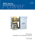
6XPPDU\DQG)HDWXUHV
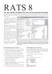
,QGRRU8QLW
*9$$+011$$,
2XWGRRU8QLW
*9$$+011$$2
5HPRWH&RQWUROOHU
<%)
FAN AUTO
OPER
AIR HEALTH X-FAN
HUMIDITY
FILTER
TURBO
HOUR
ON/OFF
ON/OFF
MODE
FAN
X-FAN
TEMP
TIMER
TURBO
SLEEP
LIGHT
5CHGV[2TGECWVKQPU
6DIHW\3UHFDXWLRQV
Installing, starting up, and servicing air conditioner can be
hazardous due to system pressure, electrical components,
and equipment location, etc.
Only trained, qualified installers and service personnel are
allowed to install, start-up, and service this equipment.
Untrained personnel can perform basic maintenance functions such as cleaning coils. All other operations should
be performed by trained service personnel.
Make sure the outdoor unit is installed on a stable, level
surface with no accumulation of snow, leaves, or trash
beside.
When handling the equipment, observe precautions in the
manual and on tags, stickers, and labels attached to the
equipment. Follow all safety codes. Wear safety glasses
andwork gloves. Keep quenching cloth and fire extinguisher
nearby when brazing.
Follow all the installation instructions to minimize the risk
of damage from earthquakes, typhoons or strong winds.
Read the instructions thoroughly and follow all warnings or
cautions in literature and attached to the unit. Consult local
building codes and current editions of national as well as
local electrical codes.
Recognize the following safety information:
Warning
Incorrect handling could result in
personal injury or death.
Caution
Incorrect handling may result in
minor injury,or damage to product
or property.
Warning
All electric work must be performed by a licensed technician
according to local regulations and the instructions given in
this manual.
Before installing, modifying, or servicing system, main
electrical disconnect switch must be in the OFF position.
There may be more than 1 disconnect switch. Lock out
and tag switch with a suitable warning label.
Never supply power to the unit unless all wiring and tubing are completed, reconnected and checked.
This system adopts highly dangerous electrical voltage.
Incorrect connection or inadequate grounding can cause
personal injury or death. Stick to the wiring diagram and
all the instructions when wiring.
Have the unit adequately grounded in accordance with
local electrical codes.
Have all wiring connected tightly. Loose connection may
lead to overheating and a possible fire hazard.
All installation or repair work shall be performed by your dealer or a specialized subcontractor as there is the risk of fire,
electric shock, explosion or injury.
Make sure the ceiling/wall is strong enough to bear the
weight of the unit.
Make sure the noise of the outdoor unit does not disturb
neighbors.
Avoid contact between refrigerant and fire as it generates
poisonous gas.
Apply specified refrigerant only. Never have it mixed with
any other refrigerant. Never have air remain in the
refrigerant line as it may lead to rupture and other hazards.
Make sure no refrigerant gas is leaking out when installation is completed.
Should there be refrigerant leakage, the density of refrigerant in the air shall in no way exceed its limited value,
or it may lead to explosion.
Keep your fingers and clothing away from any moving
parts.
Clear the site after installation. Make sure no foreign objects are left in the unit.
Always ensure effective grounding for the unit.
Caution
Never install the unit in a place where a combustible gas
might leak, or it may lead to fire or explosion.
Make a proper provision against noise when the unit is
installed at a telecommunication center or hospital.
Provide an electric leak breaker when it is installed in a
watery place.
Never wash the unit with water.
Handle unit transportation with care. The unit should not
be carried by only one person if it is more than 20kg.
Never touch the heat exchanger fins with bare hands.
Never touch the compressor or refrigerant piping without
wearing glove.
Do not have the unit operate without air filter.
Should any emergency occur, stop the unit and disconnect the power immediately.
Properly insulate any tubing running inside the room to
prevent the water from damaging the wall.
5RGEKſECVKQPU
6SHFL¿FDWLRQV
8QLW6SHFL¿FDWLRQV
3DUDPHWHU
8QLW
0RGHO
*9$$+011$$
3URGXFW&RGH
3RZHU
6XSSO\
9DOXH
9ROWDJH
)UHTXHQF\
&*
9̚
+]
3KDVHV
3RZHU6XSSO\0RGH
2XWGRRU
&RROLQJ&DSDFLW\
:
+HDWLQJ&DSDFLW\
:
&RROLQJ3RZHU,QSXW
:
+HDWLQJ3RZHU,QSXW
:
&RROLQJ&XUUHQW
$
+HDWLQJ&XUUHQW
$
5DWHG3RZHU,QSXW
:
5DWHG&XUUHQW
$
((5
::
&23
::
6((5
::
+63)
::
$LU)ORZ9ROXPH
PK
'HKXPLGLI\LQJ9ROXPH
/K
6HW7HPSHUDWXUH5DQJH
ć
̚ &RROLQJ2SHUDWLRQ$PELHQW7HPSHUDWXUH5DQJH
ć
̚ +HDWLQJ2SHUDWLRQ$PELHQW7HPSHUDWXUH5DQJH
ć
̚ $SSOLFDWLRQ$UHD
P
,QGRRU8QLW0RGHO
*9$$+011$$,
)DQ7\SH
&HQWULIXJDO
'LDPHWHU/HQJWK';/
PP
ĭ;
)DQ0RWRU6SHHG&RROLQJ6++0/6/
UPLQ
)DQ0RWRU6SHHG+HDWLQJ6++0/6/
UPLQ
)DQ0RWRU3RZHU2XWSXW
:
)DQ0RWRU5/$
$
)DQ0RWRU&DSDFLWRU
ȝ)
+HDWHU3RZHU,QSXW
:
(YDSRUDWRU)RUP
(YDSRUDWRU3LSH'LDPHWHU
,QGRRU8QLW (YDSRUDWRU5RZ¿Q*DS
(YDSRUDWRU&RLO/HQJWK/;';:
$OXPLQXP)LQFRSSHU7XEH
PP
PP
PP
;;
6ZLQJ0RWRU0RGHO
6ZLQJ0RWRU3RZHU2XWSXW
)XVH
ĭ
03$$03$%
:
$
6RXQG3UHVVXUH/HYHO6++0/6/
G%$
6RXQG3RZHU/HYHO6++0/6/
G%$
2XWOLQH'LPHQVLRQ:;+;'
PP
;;
3DFNDJH&DUWRQ'LPHQVLRQ/:+
PP
;;
3DFNDJH'LPHQVLRQ/:+
PP
;;
1HW:HLJKW
NJ
*URVV:HLJKW
NJ
5RGEKſECVKQPU
2XWGRRU8QLW0RGHO
*9$$+011$$2
&RPSUHVVRU0DQXIDFWXUHU7UDGHPDUN
'$/,$16$1<2&2035(6625&'/7'6$1<2
&RPSUHVVRU0RGHO
&6%1+'
&RPSUHVVRU2LO
'$3+1()96
&RPSUHVVRU7\SH
6FUROO
&RPSUHVVRU/5$
$
&RPSUHVVRU5/$
$
&RPSUHVVRU3RZHU,QSXW
:
2YHUORDG3URWHFWRU
,QWHUQDO
7KURWWOLQJ0HWKRG
&DSLOODU\
&RQGHQVHU)RUP
$OXPLQXP)LQFRSSHU7XEH
&RQGHQVHU3LSH'LDPHWHU
PP
ĭ
&RQGHQVHU5RZV¿Q*DS
PP
&RQGHQVHU&RLO/HQJWK/;';:
PP
;;
)DQ0RWRU6SHHG
USP
2XWSXWRI)DQ0RWRU
:
)DQ0RWRU5/$
$
)DQ0RWRU&DSDFLWRU
2XWGRRU8QLW$LU)ORZ9ROXPHRI2XWGRRU8QLW
ȝ)
PK
)DQ7\SH
)DQ'LDPHWHU
$[LDOÀRZ
PP
'HIURVWLQJ0HWKRG
$XWRPDWLF'HIURVWLQJ
&OLPDWH7\SH
7
,VRODWLRQ
,
0RLVWXUH3URWHFWLRQ
3HUPLVVLEOH([FHVVLYH2SHUDWLQJ3UHVVXUH
IRUWKH'LVFKDUJH6LGH
3HUPLVVLEOH([FHVVLYH2SHUDWLQJ3UHVVXUH
IRUWKH6XFWLRQ6LGH
,3
03D
03D
6RXQG3UHVVXUH/HYHO+0/
G%$
6RXQG3RZHU/HYHO+0/
G%$
PP
;;
'LPHQVLRQRI&DUWRQ%R[/:+
PP
;;
'LPHQVLRQRI3DFNDJH/:+
PP
;;
'LPHQVLRQ:;+;'
1HW:HLJKW
NJ
*URVV:HLJKW
NJ
5HIULJHUDQW
5HIULJHUDQW&KDUJH
/HQJWK
*DV$GGLWLRQDO&KDUJH
/LTXLG3LSH2XWHU'LDPHWHU
&RQQHFWLRQ /LTXLG3LSH7KLFNQHVV
3LSH
*DV3LSH2XWHU'LDPHWHU
5$
NJ
P
JP
PP
ĭ
PP
PP
ĭ
PP
0D[+HLJKW'LVWDQFH
P
0D[/HQJWK'LVWDQFH
P
*DV3LSH7KLFNQHVV
7KHDERYHGDWDLVVXEMHFWWRFKDQJHZLWKRXWQRWLFH3OHDVHUHIHUWRWKHQDPHSODWHRIWKHXQLW
ĭ
5RGEKſECVKQPU
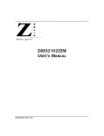
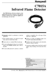
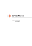
&DSDFLW\9DULDWLRQ5DWLRaFFRUGLQJWR7HPSHUDWXUH
&RROLQJ
+HDWLQJ
140
120
120
100
100
Capacity ratio (%)
Capacity ratio (%)
110
90
80
70
Condition Indoor: DB29 ,WB19
Indoor air flow: Super High
Pipe length: 5m.
60
;
50
80
60
40
Condition Indoor: DB20 ;
Indoor air flow: Super High
Pipe length: 5m.
20
32
34
36
38
40
42
44
46
48
50
52
54
Outdoor temp.( )
0
-15
-10
-5
0
5
10
15
Outdoor temp.( )
2SHUDWLRQ'DWD
&RROLQJ
7HPSHUDWXUHFRQGLWLRQ&
,QGRRU
2XWGRRU
0RGHOQDPH
*9$$+011$$
6WDQGDUG
SUHVVXUH
+HDWH[FKDQJHUSLSHWHPS
303D
7&
7&
a
aWRa
aWRa
,QGRRUIDQ 2XWGRRUIDQ
PRGHUSP PRGHUSP
+HDWLQJ
7HPSHUDWXUHFRQGLWLRQ&
,QGRRU
2XWGRRU
0RGHOQDPH
6WDQGDUG
SUHVVXUH
303D
*9$$+011$$
a
+HDWH[FKDQJHUSLSHWHPS
7&
7&
aWRa aWRa
,QGRRUIDQ 2XWGRRUIDQ
PRGHUSP PRGHUSP
127(6
0HDVXUHVXUIDFHWHPSHUDWXUHRIKHDWH[FKDQJHUSLSHDURXQGFHQWHURIKHDWH[FKDQJHUSDWK8EHQW
7KHUPLVWRUWKHPRPHWHU
&RQQHFWLQJSLSLQJFRQGLWLRQP
7,QOHWDQGRXWOHWSLSHWHPSHUDWXUHRIHYDSRUDWRU
7,QOHWDQGRXWOHWSLSHWHPSHUDWXUHRIFRQGHQVHU
33UHVVXUHRIDLUSLSHFRQQHFWLQJLQGRRUDQGRXWGRRUXQLWV
%QPUVTWEVKQP8KGYU
&RQVWUXFWLRQ9LHZV
,QGRRU8QLW
8QLWPP
%QPUVTWEVKQP8KGYU
2XWGRRU8QLW
8QLWPP
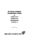
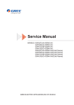
4GHTKIGTCPV5[UVGO&KCITCO
5HIULJHUDQW6\VWHP'LDJUDP
INDOOR UNIT
OUTDOOR UNIT
GAS SIDE
3-WAY VALVE
4-Way valve
Muffler
Discharge
HEAT
EXCHANGE
(EVAPORATOR)
Suction
Accumlator
COMPRESSOR
HEAT
EXCHANGE
(CONDENSER)
LIQUID SIDE
2-WAY VALVE
Strainer
Capillary
Strainer
COOLING
HEATING
5HIULJHUDQWSLSHGLDPHWHU
/LTXLGPP
*DVPP
5EJGOCVKE&KCITCO
6FKHPDWLF'LDJUDP
(OHFWULFDO'DWD
0HDQLQJRIPDUNV
Symbol
SAT
COMP
Parts name
Symbol
Color symbol
Symbol
Color symbol
BU
BLUE
VT
VIOLET
COMPRESSOR
YE
YELLOW
OG
ORANGE
PROTECTIVE EARTH
RD
RED
BK
BLACK
YELLOW GREEN
BN
BROWN
OVERLOAD
C1
CBB65
C2
CBB61
YEGN
(OHFWULFDO:LULQJ
,QGRRU8QLW
0RGHO*9$$+011$$,
5EJGOCVKE&KCITCO
2XWGRRU8QLW
0RGHO*9$$+011$$2
XT1
BN
L1
BK
L2
VT
L3
BU
N
YEGN
L1
L2
L3
N
1YEGN
PE 13BN
L1
14BK
L2
15VT
L3
VT
BU
N
YEGN
28YEGN
PROTECTOR
X1
XT2
35BN
7BU
36BK
37VT
B
1
17BU
12BU
2
38BU
T
S
R
16WH
FU
5
3
21
2
4
6
X2
1
2
3
OVERLOAD
PROTECTOR
4
1
20BU
A1
C1
8BN 9BK 10VT
(V)
(U)
COMPRESSOR
(W)
T2
BU
T1 COMP T3
3~
1
C2
OG
OG
(WH)
11BN
BN BN
(WH)
BU BN BN
(BK)
(BK)
M2
~
M1
~
E
YEGN
PE
PE
E
YEGN
FAN MOTOR
E
2
X3
XT4
0
P
HIGH PRESSURE
SWITCH
EH
18YEGN
5
FA
A
REVERSAL DEFENSIBLE RELAY
A2
22
3
4
2
KM
CONTACTOR
2
19BU
PM
29WH
5BN
1
XT3
C
1
21YE
39VT
23OG
24WH
22BK
26BU
34YE
A
OVERLOAD
33WH
27BU
BK
32BU
FA
BN
30RD
31WH
2BN 3BK 4VT
6BN
POWER
4YV
HP
LP
P
X4
DISCHARGE GAS
TEMP. SENSOR
LOW PRESSURE
SWITCH
X5
0
RT1
0
ROOM
TEMP. SENSOR
RT2
TUBE
TEMP. SENSOR
RT3
25BU
PE
7KHVHFLUFXLWGLDJUDPVDUHVXEMHFWWRFKDQJHZLWKRXWQRWLFH.POHDVHUHIHUWRWKHRQHVXSSOLHGZLWKWKHXQLW
5EJGOCVKE&KCITCO
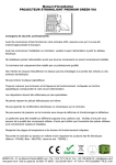
3ULQWHG&LUFXLW%RDUG
Ɣ7239,(:
1
2
3
4
5
6
7
8
1
2
3
4
5
6
9
7
8
9
10
11
12
13
13
12
11
Copper insert of live wire
Protective tube
Copper insert of wire of
compressor
Control relay of compressor
Copper insert of wire of
outdoor fan
Copper insert of wire of
4-way valve
Copper insert of neutral wire
Wiring terminal of indoor fan
Relay of auxiliary heater
Terminals of DISP1 and
DISP2
Control relay for 4-speed of
indoor fan
Control relay of 4-way valve
Control relay of outdoor fan
10
Ɣ%277209,(:
(WPEVKQPCPF%QPVTQN
)XQFWLRQDQG&RQWURO
5HPRWH&RQWURO2SHUDWLRQV
1
)$1
$87 2
ON/OFF
Press it to start or stop operation.
23(5
2
$,5 +($/ 7+ ;)$1
+80,',7<
MODE
Press it to select operation mode (AUTO/COOL/DRY/FAN/HEAT).
),/7(5
3
785%2
Press it to decrease temperature setting.
+285
212))
4
+
Press it to increase temperature setting.
1
212))
2
02'(
3
5
Press it to set fan speed.
6
4
Press it to set swing angle.
7
5
6
)$1
7
9
;)$1
10
12 785%2 13
7(03
6/((3
7,0(5
/,*+7
FAN
HEALTH SAVE
Press it to turn on or off health function.
8
8
11
9
Press it to set left & right swing angle.
X-FAN(X-FAN is the alternative expression of BLOW for the
purpose of understanding.)
14
TEMP
11 TIMER
10
Press it to set timer ON/ timer OFF.
12
13
14
TURBO
SLEEP
LIGHT
Press it to turn on/off the light.
24
FAN
AUTO
OPER
AIR HEALTH X-FAN
HUMIDITY
15
16
17
18
15
MODE icon:
If MODE button is pressed, current operation mode icon
FILTER
23
TURBO
HOUR
ON/OFF
22
21
19
20
(AUTO),
( COOL),
(DRY),
(FAN) or
(HEAT is only for heat
pump models) will show.
16
LOCK icon:
17
LIGHT icon:
is displayed by pressing "+" and “-” buttons simultaneously. Press them again to clear the display.
is displayed by pressing the LIGHT button. Press LIGHT button again to clear the display.
18
SLEEP icon :
is displayed by pressing the SLEEP button. Press this button again to clear the display.
19
TEMP icon:
Pressing TEMP button,
circularly.
(set temperature),
(ambient temperature) ,
(outdoor ambient temperature) and blank is displayed
(WPEVKQPCPF%QPVTQN
20
Up & down swing icon:
21
Left & right swing icon:
22
SET TIME display:
is displayed when pressing the up & down swing button. Press this button again to clear the display.
is displayed when pressing the left & right swing button.Press this button again to clear the display.
After pressing TIMER button, ON or OFF will blink.This area will show the set time.
23
DIGITAL display:
This area will show the set temperature. In SAVE mode,"SE" will be displayed. During defrosting operation, “H1” will be displayed.
24
FAN SPEED display:
Press FAN button to select the desired fan speed setting(AUTOLow-Med-High).Your selection will be displayed in the LCD windows,
except the AUTO fan speed.
Remote controller description
1
ON/OFF:
Press this button to turn on the unit. Press this button again to turn off the unit.
2
MODE:
Each time you press this button,a mode is selected in a sequence that goes from AUTO, COOL,DRY, FAN, and HEAT *, as the
following:
AUTO COOL
DRY FAN
HEAT*
*Note: Only for models with heating function.
After energization, AUTO mode is defaulted. In AUTO mode, the set temperature will not be displayed on the LCD, and the unit will
automatically select the suitable operation mode in accordance with the room temperature to make indoor room comfortable.
3
+:
Press this button to increase set temperature. Hold it down for above 2 seconds to rapidly increase set temperature. In AUTO mode,
set temperature is not adjustable.
4
-:
Press this button to decrease set temperature. Hold it down for above . 2 seconds to rapidly decrease set temperature. In AUTO
mode, set temperature is not adjustable.
5
FAN :
This button is used for setting fan speed in the sequence that goes from AUTO,
,
,
to then back to Auto.
AUTO
Low speed
Medium speed
High speed
6
●Press
button to start or stop up & down swing function.The remote controller defaults to simple swing condition.
●Press + button and
button at the same time at unit OFF to switch between simple swing and static swing;
blinks for 2
seconds.
●In static swing condition, pressing
button, the swing angle of up & down louver changes as below:
OFF
●If the unit is turned off during swing operation,the louver will stop at present position.
7
HEALTH SAVE:
Press HEALTH part of this button to turn on or off HEALTH function.Pressing SAVE part of this button,"SE" is displayed and the unit
goes into SAVE operation mode. Press SAVE part of the button again to cancel SAVE function. During SAVE operation, the temperature and fan speed is not adjustable.
8
●Press
button to start or stop left & right swing function.The remote controller defaults to simple swing condition.
●Press + button and
button at the same time at unit OFF to switch between simple swing and static swing;
blinks for 2
seconds.
(WPEVKQPCPF%QPVTQN
●In static swing condition, pressing
button, the swing angle of left & right louver changes as below:
OFF
●If the unit is turned off during swing operation,the louver will stop at present position.
9
X-FAN:
Pressing X -FAN button in COOL or DRY mode,the icon "X-FAN" is displayed and the indoor fan will continue operation for 10
minutes in order to dry the indoor unit even though you have turned off the unit. After energization, X-FAN OFF is defaulted. X-FAN
is not available in AUTO, FAN and HEAT mode.
10
TEMP:
Press this button, could select displaying the indoor setting temperature or indoor ambient temperature.When the indoor unit firstly
power on it will display the setting temperature, if the temperature's displaying status is changed from other status to"
",displays
the ambient temperature, 5s later or within 5s, it receives other remote control signal that will return to display the setting temperature. if the users haven't set up the temperature displaying status,that will display the setting temperature.
11
TIMER:
Press TIMER button at unit ON to set TIMER OFF; HOUR OFF blinks. Press TIMER button at unit OFF to set TIMER ON; HOUR
ON blinks. In this case, pressing + or - button changes time setting. Holding down either button rapidly changes time setting (time
setting range 0.5-24hours). Press TIMER button again to confirm setting; HOUR ON/OFF stops blinking. If there is not any operation
of button within 5 seconds during HOUR ON/OFF blinking, TIMER setting will be cancelled.
12
TURBO:
Press this button to activate / deactivate the Turbo function which enables the unit to reach the preset temperature in shortest time.
In COOL mode, the unit will blow strong cooling air at super high fan speed. In HEAT mode, the unit will blow strong heating air
at super high fan speed.
13
SLEEP :
Press this button to go into the SLEEP operation mode. Press it again to cancel this function. This function is available in COOL ,
HEAT (Only for models with heating function) or DRY mode to maintain the most comfortable temperature for you.
14
LIGHT:
Press LIGHT button to turn on the display's light and press this button again to turn off the display's light. If the light is turned on ,
is displayed. If the light is tunrned off,
disappears.
15 Combination of "+" and "-" buttons: About lock
Press "+ " and " " buttons simultaneously to lock or unlock the keypad. If the remote controller is locked,
case, pressing any button,
is displayed. In this
blinks three times.
16 Combination of "MODE" and "-" buttons:About switch between Fahrenheit and Centigrade.At unit OFF, press "MODE" and "- "
buttons simultaneously to switch between ℃ and ℉ .
Replacement of Batteries
1.Remove the battery cover plate from the rear of the remote controller.
(As shown in the figure)
2.Take out the old batteries.
3.Insert two new AAA1.5V dry batteries, and pay attention to the polarity.
4. Reinstall the battery cover plate.
★Notes:
●When replacing the batteries, do not use old or different batteries,
otherwise, it may cause malfunction.
●If the wireless remote controller will not be used for a long time, please
remove batteries to prevent damage from leaking batteries.
●The operation should be performed in its receiving range.
●It should be kept 1m away from the TV set or stereo sound sets.
●If the wireless remote controller does not operate normally, please take
the batteries out and reinsert them after 30 seconds. If it still can't operate
properly, replace the batteries.
Sketch map for
replacing batteries
(WPEVKQPCPF%QPVTQN
)XQFWLRQ%XWWRQVRI$LU&RQGLWLRQHU
Buttons function and displayer
E-HEATER
Speed
ON/OFF
●
●
Function
AMB.
and
and
ON/OFF Button
Press this button, to turn on the unit.
When unit is turned on, the original
setting like Timer, Sleep function will
be canceled.Note: When the unit is
running in Dry mode, press ON/OFF
button that can turn on the unit directly.
●
●
When the unit start up running,
the status light will display in red
indicated as power turn-on and free-duty.
Mode
●
Mode Button
Press the button, the circulating changes
of mode are shown as below:
AUTO
COOL
DRY
HEAT
FAN
AUTO: the controller will determine its
operation mode according to changes
of room temperatures under this mode.
COOL: display cooling state.
DRY: reduce temperature
and keep the setting room temperature
without any change.
FAN: The compressor doesn't on
work and only the indoor blower is on
running under this mode.
HEAT: Display the state of heating .
(Note: Single-cooling machine is not
equipped with heating mode)
Mode
●
ON/OFF
Button
Under the situation without setting
the function, press and buttons,
the setting temperature goes up
and down 1 , the regulating range
is from 16 to 30 .
Under the conditions of setting the
functions, can proceed with the
round-trip option of this function (set
and opposite direction of
circulation).
Keep pressing and buttons
for 3 seconds continuously, functions
of all buttons on the display panel
will be conductively-closed, and then
press any button, the buzzer will
ring once while "LC" is flashing for
three times on the location of double
8 and resume to normal display so
as to prompt users that the buttons
have been locked up.When keep
pressing again the two buttons for
another 3 seconds continuously,
the function of lockup will be removed
and resume to display in normal state.
(WPEVKQPCPF%QPVTQN
Buttons function and displayer
E-HEATER
and
●
Function
Speed
and
Buttons (Continued)
After switch-on at first time, if without
any button input:1. consecutively press
twice of
buttons in 20 seconds and
soon access to the running of forced
heating.After the blades of blowing up
and down opens to the minimum position,
start up running of all loads, indoor and
outdoor high-speed blowers. All characters
will be displayed when the non-inductive
thermometer bulb is broken down. The
fault codes of breakdown will be displayed
when the inductive thermometer bulb is
broken down and then the buzzer rings.
After shutdown for five minutes or
receiving shutdown signal within 5
minutes, it enter the status of normal
standby. 2. consecutively press twice
of
buttons in 20 seconds and soon
access to the running of forced cooling.
After the blades of blowing up and down
opens to the minimum position,start up
running of all loads, indoor and outdoor
high-speed blowers besides the fourway valve and then the buzzer rings.
After shutdown for five minutes or
receiving shutdown signal within 5
minutes,it enter the status of normal
standby.
The 1 and 2 Functions are for trial use
only.
AMB.
Speed
Mode
ON/OFF
Speed Button
Press this button, the speed can
shift in the circulation among of
“ Auto → Low → Medium →High
→Super →Auto”
Note: the function of forced low
speed under operation of dehumidification is not available.
●
AMB.
●
AMB. Button
Press this button, AMB. circulating
changes set forth below:
Energy saving
Normal
●
Restaurant
Living Room
Conference/Office
Adjustable method of AMB.
Button:The switch-on of AMB. mode
at first time is the default of normal
mode,when shutting down and
starting up again,the AMB. mod will
keep the setting status before last
shutting down. Under the modes of
energy-saving, conference/office
and restaurant,the sleep function
will be automatically cancelled.
And the sleep function is not
adjustable: sleep function is only
available on service for cooling,
dehumidification and heating under
normal mode.
(WPEVKQPCPF%QPVTQN
Buttons function and displayer
E-HEATER
Speed
AMB.
●
●
●
AMB.
Function
AMB.
AMB. Buttons (Continued)
Mode
ON/OFF
AMB.Buttons (Continued)
● The modes of living room, restaurant,
Under the modes of living room,
conference/office can only be called
restaurant, conference/office,The
out by pressing buttons of air consetting temperature, speed, blowing
ditioner panel. If receiving the signal from remote control when the
up and down as well as left and right
air
conditioner is running the modes
can be adjustable. If users change
of
living
room, restaurant, conferethe setting temperature, speed,
nce/office,
it will exit from the aboblowing up and down as well as
vementioned modes and run accleft and right, the operation will run
ording to the modes of remote control.
in accordance with the status of setting
Function
adjustment. The services setting of
Function Button
blowing up and down as well as left
● Under the status of switch-on, Every
and right of next time start-up will be
time press the function button, the
remained before last shutdown while
settings of up and down, left and right,
the setting temperature and speed
drying, concurrent heating, timing, air
will run with the default.
renewal, setting and room temperature
Under the energy-saving mode, while
can
be shifted in sequence. When a
the heating service is on running, the
certain
character is flashing, it insetting temperature, speed, blowing
dicates
can proceed its setting and
up and down as well as left and
go
on
setting
by press buttons.
right can be adjustable. If users
The
action
will
be confirmed if
change the setting speed, blowing
without
receiving
other operating
up and down as well as left and right,
order
in
5
seconds.
Or press the
it will run according the status of users'
function
button
to
leave
for the confirm.
setting adjustment. But the setting
● Press the function button under the
temperature under the energy-saving
status of running drying service
cooling function can not be adjusted.
can directly proceed shutdown.
Press the function button under
the status of shutdown and nondrying can proceed timing setting.
(WPEVKQPCPF%QPVTQN
Buttons function and displayer
E-HEATER
Speed
AMB.
Function
Swing
Mode
ON/OFF
Status of swing
●
Display status of swing.
Setting
●
Display setting temperature.
Swing
Room temperature
●
Indicate temperature of indoor
circumstances.
●
BLOW
Supper strong
●
SAVE
When the typeface light is on, it
indicates setting the super strong
function.
Status of swing
BLOW Function
●
When the typeface light is on, it
indicates setting the BLOW function.
E-HEATER
E-HEATER Function
Mode of save
●
●
ROOM
Indicate mode of save.
Mode of room
●
TIMER Function
Office mode
●
RESTAURANT
COMMON
Indicate mode of restaurant.
Common mode
●
●
Indicate mode of office.
Mode of restaurant
●
This icon on the displayer turns
on,indicates that the E-HEATER
function turned on,the electrical
heating, according to a certain
condition, it can put into use.
Indicate mode of room.
TIMER
OFFICE
Display status of swing.
Indicate common mode.
SLEEP
When the typeface light is on, it
indicates setting the timer function.
SLEEP Function
●
When the typeface light is on, it
indicates setting the sleep function.
(WPEVKQPCPF%QPVTQN
'HVFULSWLRQRI(DFK&RQWURO2SHUDWLRQ
1. Running Mode
1. cooling;
2. dry;
3. fan;
4: heating;
5. AUTO;
6. others (Freon recovery mode).
2. Temperature Para meter
1. Indoor ambient temperature Tamb. (adopt 15K temperature sensor, external connect 15K partial resistance);
2. Outdoor ambient temperature Toutdoor amb. (adopt 15K temperature sensor, external connect 15K partial resistance);
3. Discharge temperature (Tdischarge)
4. Indoor evaporator tube temperature Tevaporator (adopt 20K temperature sensor, external connect 20K partial resistance);
5. Outdoor condenser tube temperature Tcondenser (adopt 20K temperature sensor, external connect 20K partial resistance).
3. Basic Functions of System
In all modes, once the compressor is started up, it will run within 6mins all the time; once the compressor is stopped, it can only be started
up after 3mins delayed.
( 1 ) Cooli ng Mode
1. Working conditions and process of cooling
When Tamb.≥ Tpreset+1ć, the unit will run in cooling mode. Meanwhile, compressor, outdoor fan will start running, and indoor will run at
setting fan speed;
When Tamb.̰Tpreset-1ć, the unit is at OFF status in cooling mode. Meanwhile, compressor, outdoor fan will all stop running, while
indoor fan will run at setting fan speed;
When Tpreset-1ć<Tamb.<Tpreset+1ć, the unit will keep previous running status.
In this mode, the temperature setting range is 16ć~30ć and the initial value is 25ć.
Tamb.
start cooling
Tpreset+1℃
original running status
Tpreset-1℃
stop cooling
mins
mins
mins
compressor
outdoor fan
setting fan speed
indoor fan
stop
run
( 2 ) Dry Mode
1. Working conditions and process of dry
When Tamb.>Tpreset+2ć, the unit will run in cooling mode. Meanwhile, compressor and outdoor fan will start running, and indoor fan will
run at low fan speed;
When Tpreset-2̰Tamb.̰Tpreset+2ć, compressor and outdoor fan will run for 6mins and then stop for 4 mins, and they will run like that
circularly. Indoor fan will run at low fan speed;
When Tamb.<Tpreset-2ć, compressor and outdoor fan will stop running, while indoor fan will run at low fan speed.
In this mode, the temperature setting range is 16ć~30ć and the initial value is 25ć.
Tamb.
cooling
Tpreset+2℃
drying
Tpreset-2℃
6mins
stop running
6mins
4mins
4mins
compressor
outdoor fan
indoor fan
low fan speed
run
low fan speed
low fan speed
stop
(WPEVKQPCPF%QPVTQN
( 3 ) Heating Mode ( this mode is not available for c ooling only un it)
1. Working condition and process for heating
When Tamb.̰Tpreset-1ć, the unit will run in heating mode. Meanwhile, compressor and outdoor fan will start running. Indoor fan may
be start running after delayed for a period of time to prevent blowing out cold air. If the unit turns to heating mode for the first time or
switches to heating mode from other modes, the four-way valve will be energized after compressor was started up for the first time for 20s.
When Tamb.≥ Tpreset+1ć, compressor and outdoor fan will stop running. The four-way valve is energized all the same and indoor fan
will stop running after running at low fan speed for 10s;
When Tpreset-1ć<Tamb.<Tpreset+1ć, the unit will keep original running status;
In this mode, the temperature setting range is 16ć~30ć and the initial value is 25ć. When tuning off the unit in heating mode or
switching to other modes from heating mode, the four-way valve will be de-energized after 2mins delayed.
When turning off the unit, if the complete unit is at running status in heating mode, the unit will stop running when reaching the
setting temperature and the unit will be turned off after lowing residual heat for 10s. If the unit is at the status of blowing residual
heat when the unit is stopped after reaching the temperature point, the unit will continue to blow residual heat and then it will be
turned off; if the unit is stopped after reaching the temperature and indoor fan is stopped, the unit will be turned off directly without
blowing residual heat.
stop heating
Tpreset
original running status
Tpreset
Tamb
start heating
mins
mins
mins
setting fan speed
compressor
outdoor fan
indoor fan
anti cold air
low fan speed
anti cold air
low fan speed
reversing valve
run
stop
2. Defrosting condition and process
System will defrost intelligently and automatically. When it’s detected that the system is reached the defrosting condition, the system will
turn to defrosting status;
After defrosting is started up, H1 will be displayed. If there’s auxiliary heating, auxiliary heating will be stopped and then compressor,
indoor fan and outdoor fan will stop running after 1min delayed. 3mins later, the four-way valve will be closed. After four-way valve has
closed for 30s, compressor will be started up.
After defrosting is finished, compressor will stop running, while the four-way valve will be start up. 30s later, compressor and outdoor fan
will be restarted up and turn to the next periods. Indoor fan is running at anti cold air status.
Defrosting time can’t exceeds 12mins at the most.
3. Working condition for auxiliary heating
Auxiliary heating can be turned on/off by buttons.
If auxiliary heating is at ON status, when indoor fan is running, and indoor ambient temperature and air discharge temperature are low,
auxiliary heater will start running;
When indoor fan isn’ t running, or indoor ambient temperature is high, or air discharge temperature is high, auxiliary heater will stop
running. Once the auxiliary heater is stopped, it can only be restarted up after 2mins delayed.
If auxiliary heating is set OFF, the auxiliary heating will be turned off directly.
˄ 4 ˅Fan Mo de
Indoor fan is running at setting fan speed:
auto fan speed
low fan speed
medium fan speed
high fan speed
The temperature setting range is 16ć~30ć and the initial value is 25ć.
( 5 ) Auto Mode
In this mode, the system will select the running mode (cooling, dry, heating, fan) automatically according to the change of ambient
temperature.
Once the mode is started up, the unit will only switch to the running status under auto mode according to Tamb after it has run for
30s at least.
(WPEVKQPCPF%QPVTQN
˄ 6 ˅Freon Recovery Mode
That’s the recovery operation method for refrigerant:
1. After the A/C is energized for the first time, set the A/C at FAN mode, low fan speed by remote controller and the indoor
temperature is set as 20ć; Meanwhile, indoor fan will start running.
2. Press the light button on remote controller for twice successively within 5s; meanwhile, indoor fan and compressor will start running
automatically.
3. After compressor has run for 3mins, close the cut-off valve completely.
4. When the protector for low-voltage switch has an action, compressor and outdoor unit will stop running automatically. Please close
the cut-off valve immediately.
5. After stopping blowing wind by remote controller, the refrigerant recovery operation is finished completely.
Notice: 1. After refrigerant is recovered, if the recovery operation should be operated again, please cut off the power at first and then put
through the power again.
2. Above methods are applicable for the movement or reinstallation of indoor unit or outdoor unit; during this process, the low
voltage switch can’t be short circuited.
4. Other Controls
1. Sleep Function
Sleep in cooling mode:
When initial temperature is set as 16~23ć, after sleep function is started up, the temperature will increase by 1ć every 1hr. After the
temperature has increased by 3ć, the unit will keep this temperature. After the unit has run for 7hrs, the temperature will decrease 1ć
and then the unit will run at this temperature all the time.
When initial temperature is set as 24~27ć, after sleep function is started up, the temperature will increase by 1ć every 1hr. After the
temperature has increased by 2ć, the unit will keep this temperature. After the unit has run for 7hrs, the temperature will decrease 1ć
and then the unit will run at this temperature all the time.
When initial temperature is set as 28~29ć, after sleep function is started up, the temperature will increase by 1ć every 1hr. After the
temperature has increased by 1ć, the unit will keep this temperature. After the unit has run for 7hrs, the temperature will decrease 1ć
and then the unit will run at this temperature all the time.
When initial temperature is set as 30 ć, the unit will run at this temperature. After the unit has run for 7hrs, the temperature will
decrease by 1ć and then the unit will run at this temperature all the time.
Sleep in heating mode:
When initial temperature is set as 16ć, the unit will run at this temperature all the time;
When initial temperature is set as 17~20ć, after sleep function is started up, the temperature will decrease by 1ć every 1hr. After the
temperature has decreased for 1ć, the unit will keep this temperature.
When initial temperature is set as 21~27ć, after sleep function is started up, the temperature will decrease by 1ć every 1hr. After the
temperature has decreased for 2ć, the unit will keep this temperature.
When initial temperature is set as 28~30ć, after sleep function is started up, the temperature will decrease by 1ć every 1hr. After the
temperature has decreased for 3ć, the unit will keep this temperature.
Sleep in dry mode:
When setting sleep function in dry mode, after the sleep function has run for 1hr, Tpreset will increase by 1ć and it will increase by
another 1ć after 2hrs. Tpreset will increase by 2ć at all within 2hrs and then the unit will run at this temperature.
Sleep in fan mode and auto mode:
Sleep function is nor available in fan mode and auto mode.
2. Timer Function
Timer ON: Timer ON can be set at the OFF status of the unit. After timer ON is reached, controller will run according to the setting mode.
The time setting range is 0.5~25hrs and the interval is 0.5hr. If the time on display screen is less than 10hrs, the display interval is 0.5hr;
if the time is more than 10hrs, the display interval is 1hr.
Timer OFF: Timer OFF can be set at the ON status of the unit. After timer OFF is reached, the unit will be turned off. The time setting
range is 0.5~25hrs and the setting interval is 0.5hr. If the time on display screen is less than 10hrs, the display interval is 0.5hr; if the
time is more than 10hrs, the display interval is 1hr.
3. Swing Control
Swing motor can be turned on/off by pressing the swing button on remote controller. Swing is valid only when the indoor fan is running.
Right & left swing: swing blade has 7 kinds of status: ķ angle 1, ĸ angle 2, Ĺ angle 3,
ĺangle 4, Ļ angle 5, ļ swing, Ľ stop. After the unit is turned on by the ON/OFF button on
control panel every time, the default status of swing is OFF and the position is Ĺ angle 3.
After the unit is turned on by remote controller, the status of swing motor is basing on the
( 0°)
set this place as the starting point
display status on remote controllerˊAfter the unit is energized every time, right & left swing
motor will be reset.
UP & down swing: when turning off the unit, the swing blade will stop at the starting point (zero
position). When turning on the unit, there are 7 kinds of status: ķ angle 1 (max position), ĸ angle
2, Ĺangle 3, ĺangle 4, Ļangle 5 (min position), ļswing, Ľstop. If turn on the unit by the
ON/OFF button on control panel, the setting swing status is basing on the status before turning off
the unit; while if turn on the unit by remote controller, the setting swing status is basing on the
status on remote controller (if the receiving remote controller is 35, 25, 24, 14 or 13, it’s ļ
swing). When turning on the unit each time (including turn on the unit by remote controller or
control panel), if the setting swing status is not Ľstop, then it will at the actual swing status; if the
setting swing status is Ľstop, after turning the unit, it will be defaulted at angle 3 in cooling, angle
4 in heating and angle 3 in dry. As for mode switchover, it will also switch like that until the setting
set this place as the starting point (0° )
swing status is not Ľstop, then the above compulsory default status will be cancelled.
(WPEVKQPCPF%QPVTQN
When turning on the unit each time, the swing blade must be open to angle 5 (mini position), and then compressor, fan etc. can run.
When switching on controller or turning off the unit each time, the swing blade must be at OFF status.
4. Buzzer
Upon energization or operation, the buzzer will give out pleasant sound (digital chord).
5. Auto Fan Speed Control of Indoor fan
In auto fan speed, indoor fan will select high, medium or low fan speed automatically according to the change of ambient temper ature.
For the switchover between any two kinds of fan speed, the unit must be make sure that it has run at each fan speed for 3mins and 30s
at least.
6. AIR Function˄it’s reserved for some models ˅
AIR function is invalid when the unit is turned off. Upon receiving the order for starting up AIR function from remote controller or control
panel, indoor fan will be turned on and the AIR function will be started up; once receiving the order for turning off AIR function, AIR
function will be turned off. After the unit is turned off, AIR function will be cleared automatically.
7. X-FAN function
X-FAN function can be turned on/off by the FUNCTION button on control panel or X-FAN E-HEATER button on remote controller.
If start up X-FAN function in cooling or dry mode, after the unit is turned off, indoor unit will still run for a few minutes to dry the water
inside the unit, and then the indoor unit will be turned off automatically.
8. Turbo Function
In cooling and heating mode, turbo function can be turned on/off (there’s no turbo function in auto, dry and fan mode) by the turbo button
After pressing turbo button for once, remote controller will display the characters of “turbo” and fan speed won’t change, Meanwhile,
indoor fan will run at super-high fan speed and display panel will display the super-high fan speed; After repressing turbo button, the
turbo function will be quitted and the characters of “turbo” on remote controller will be disappeared. Meanwhile, indoor fan will turn back
to setting fan speed. Super-high fan speed will also be quitted after operating the fan speed button and the fan speed will also be
changed correspondingly. Display panel will display the setting fan speed.
Turbo function is default to be turned off when remote controller is energized.
When restarting up the unit or switching the mode, turbo function will be memorized.
When restarting up the unit by remote controller and controller or switch to cooling or heating mode, turbo function will be memorized.
While when switching to auto, dry or fan mode, the turbo function is unavailable.
9. Power-off Memory Function
When re-energizating the unit after power failure, the unit will run at the memory content. Memory content : mode, up&down swing
(7kinds of status), right and left swing (7 kinds of status), setting temperature, setting fan speed, light, timer, turbo, AIR, health and
environment mode.
If the unit is at ON status after power failure, compressor will be started up 3mins delayed after energization; if the unit is at OFF status,
compressor will be started up without 3mins delayed.
If the timer hasn’t been reached before power failure, the unit will time again according to the setting timer before power failure.
5 Protective Measures
1. Indoor antifreezing protection
When cooling in cooling mode or dry mode (that’s Tamb>Tpreset+2ć), if it’s detected that the evaporator tube temperature is too low
the system will turn to antifreezing protection status. Meanwhile, compressor and outdoor fan will stop running, while indoor fan and
swing motor will keep original status. When evaporator tube temperature resumes to normal range and compressor has stopped for
6mins, controller will run at the setting mode.
Buttons won’t be shielded during the antifreezing protection.
2. High-pressure protection of system
When the high-pressure protection is detected for 3s successively, all loads will be turned off. Meanwhile, all buttons and signal will be
shielded and E1 will be displayed. When it’s detected that the high-pressure protection of compressor has been released for 6s
successively, the shield for button and signal will be released and E1 will still be displayed. E1 can be cleared after pressing ON/OFF
button to turn off the unit. The unit will resume running after repressing ON/OFF button.
3. Low-voltage protection of system
This function is unavailable for some modes. But if the controller is the general controller and the shielded wire of low-pressur
protection is loosened or not connected well, it will take it as low-pressure protection by mistake. The details are as below:
1. After compressor is started up for 2mins, it will begin to detect the signal of low pressure switch. If it’s detected that the low pressure
switch is broken for 1mins successively, the complete unit will stop running. 3mins later, if the low pressure switch is resumed, the unit
will resume running automatically. If low pressure switch protection occurs for 2 times successively, E3 will be displayed and the
can’t resume running automatically to warn users that it’s leaking. After restarting up the unit and low pressure switch is resumed, the
unit will resume running.
(WPEVKQPCPF%QPVTQN
2. When compressor is stopped, if it’s detected that the low pressure switch is broken for 30s successively, the complete unit will stop
running. Meanwhile, E3 will be displayed and the unit can’t resume running automatically. Only after restarting up the unit and the low
pressure switch is resumed, the unit can resume sunning.
3. When compressor hasn’t been start up after energization each time, if it’s detected that the low pressure switch is broken for 1s
successively, all loads won’t be turned on after turning on the unit, and E3 will be displayed on the display screen. E3 will still be
displayed after restarting up the unit. Only when the low pressure switch is resumed, E3 will be cleared and then all loads will run
normally.
4. In compulsory cooling or heating mode, it will begin to detect the signal of low pressure switch after compressor has started up for
2mins. When it’s detected that the low pressure switch is broken for 1s successively, the complete unit will stop running and E3 will be
displayed. During compulsory heating, if outdoor ambient temperature ̰0ć, the detection for low pressure switch will be shielded.
Correct disposal method: after cutting off the power, insert the shielded wire again to make sure that the shielded wire is connected
firmly and then restart up the unit.
4. High temperature protection for discharge pipe
After the compressor is started up, if it’s detected that the discharge temperature is too high for 30s successively, the unit will stop
running when indoor ambient temperature is reached to setting temperature. When compressor has stopped for 3mins and discharge
temperature resumes to normal range Tdischarge <90ć, the complete unit will resume running.
If above protection is occurred for twice successively, the complete unit can’t resume running and E4 will be displayed. When restarting
up the unit and Tdischarge <90ć, the unit will run at setting mode.
If turning on the unit to turn to heating mode or switching to heating mode from other modes, discharge protection will be shielded for
1min when compressor is started up for the first time.
5. Indoor high temperature resistance protection
In heating mode, when it’ s detected that the evaporator tube temperature is too high, outdoor fan will stop running; when evaporator
tube temperature resumes to normal range, outdoor fan will be started up.
6. Overcurrent protection
After compressor is started up, if it’s detected that the current is exceeds I0 (I0=25A) for 3s successively, the unit will stop running when
Indoor ambient temperature is reached to setting temperature. After compressor has stopped for 3mins, the unit will resume original
running status. If protection times exceeds 6 times, indicator will blink and display E5 and the unit can’ t resume original running status.
The unit can only resume running after restarting up the unit.
7. Malfunction of temperature sensor
Under ON status, it will detect the malfunction of indoor tube temperature (exclude defrosting period and the period when defrosting is
finished for 5mins) and outdoor discharge temperature sensor (in heating mode, it starts detecting the malfunction after compressor has
started up for 1min; the malfunction won’ t be detected when compressor is stopped). It’ s the malfunction when they are short circuit
or broken circuit for 30s successively. When there’ s malfunction of temperature sensor, the complete unit will stop running. Meanwhile
the indicator will blink and display the corresponding error code. Malfunction of temperature sensor won’ t shield the button and remote
controller.
8. Malfunction and protection code
E1: high-pressure protection of system;
E3: low-pressure protection of system;
E4: high temperature protection for discharge pipe;
E5: overcurrent protection;
F1: malfunction of indoor ambient temperature sensor;
F2: malfunction of indoor tube temperature sensor;
F3: malfunction of outdoor ambient temperature sensor
F4: malfunction of outdoor tube temperature sensor
F5: malfunction of discharge temperature sensor
When multiple malfunctions are occurred simultaneously, each malfunction error will be displayed for 3s and they be will displayed in
cycle.
6 Button
When remote controlling by remote controller:
1.If the display mode for remote controller is the heating mode and A/C is the cooling only type, A/c won’t receive other signal except
the signal for turning off the unit.
2.If pressing the invalid button on remote controller, the buzzer will still give out a sound but the function won’t be carried out.
There are those buttons on the panel: ON/FF button, mode button, ambient setting button, ▲ button, ▼button, function button, fan
speed button.
Display screen:
Speed
Function
AMB.
Mode
ON/OFF
(WPEVKQPCPF%QPVTQN
1. ON/OFF button
Controller is turned on/off by pressing this button. After each pressing of this button, the on/off status will be switched for once.
2. Mode button
After pressing this button, it will be selected and displayed as below:
Auto
cooling
dry
fan
heating
(heat pump type)
3. Ambient setting button
After pressing AMB. button, it will be selected as below:
SAVE mode
room mode
office mode
restaurant mode
common mode
ķ In each mode, after pressing AMB. mode on control panel, the ambient mode can be selected and cycled as : SAVE mode---room
ĸ
Ĺ
ĺ
Ļ
mode---office mode---restaurant mode---common mode; when the unit is turned on for the first time, ambient mode is default as
common mode; when restarting up the unit, ambient mode will keep the setting status before turning off the unit.
When using the remote controller, the unit can only turn to SAVE mode or common mode after receiving the order from remote
controller, and the unit will run according to the order transmitted by remote controller all the time.
In SAVE mode, room mode, office mode or restaurant mode, sleep will be cancelled automatically and sleep can’t be adjusted;
Sleep is only valid in cooling, dry and heating mode under the common mode.
Room, restaurant and office modes
Cooling and heating mode: setting temperature, fan speed and swing will run at the default status. If users have adjusted the
parameters, they will run according to adjusting status. 30mins later, it will turn back to auto adjusting status; when restating the
unit, swing will keep the status before turning off the unit.
Fan, dry and auto mode: running status is the same as that in common mode.
SAVE mode
In cooling mode: setting temperature and fan speed can be adjusted automatically; if users have adjusted the setting temperature
and setting fan speed, it will run according to the adjusting status. 30mins later, it will turn back to auto adjusting status.
Heating, fan, dry and auto mode: the running status is the same as that in common mode.
Notice: room, restaurant and office mode can only be adjusted by buttons on control panel. If controller is receiving the order from
remote controller when it’s running in room, restaurant or office mode, those modes will be quitted and it will run according to the
mode on remote controller.
4. Selection button for setting temperature ( ▲and ▼)
(1) During the status when don’t set the function, after pressing ▲ button or ▼button for once, the setting temperature will increase or
decrease for 1ć and the temperature setting range is 16ć~30ć.
(2) During the status when setting the function, the function can be selected circularly. ˄the circulatory direction for ▲and▼ is opposite˅
ķ up & down˄swing˅
˖swing, stop swinging.
ĸ right & left (swing): swing, stop swinging.
Ĺ blow: start up blow, turn off blow.
ĺ E-HEATER: start up E-HEATER, turn off E-HEATER.
Ļ TIMER: set timer and it can be adjusted among 0~24hrs. If the time is less than 10hrs, the interval is 0.5hr; if the time is more than
10hrs, the interval is 1hr.
ļ AIR: start up AIR, turn off AIR.
Ľ Sleep: start up sleep, turn off sleep.
ľ Health: start up the electrostatic dedusting, turn off the electrostatic dedusting.
Ŀ Turbo: start up turbo, turn off turbo.
(WPEVKQPCPF%QPVTQN
ŀSetting: default to display the setting temperature at ON status, default to display the setting temperature at off status
ŋ Room temperature: default to display room temperature at on status, default to display to room temperature at off status.
(3) After pressing ▲ button and ▼button simultaneously, all buttons on the display panel will be shielded. When pressing any buttons,
the buzzer will give out a sound and dual 8 will display “LC”. The display will resume normal after the dual 8 blinks 3 times to warn users
that the buttons are locked. When repressing those two buttons simultaneously, shield will be released and the display will resume
normal status.
(4) After the unit is energized for the first time, if there isn’t any input:
ķ If pressing ▲ buttons within 20s successively, the unit will turn to compulsory heating immediately and up & down swing blade will
open to angle I ˄minimum position˅. Meanwhile, all loads will be started up and indoor fan and outdoor fan will run at high fan speed.
When there’s no malfunction of temperature sensor, all characters will be displayed. When there’s malfunction of temperature sensor,
dual 8 will display error codes circularly and the buzzer will give out sound. When the unit is stopped 5 mins later or the unit is stopped
after receiving the signal for turning off the unit within 5mins, the unit will turn to normal standby status.
ĸ If pressing ▼button within 20s successively, the unit will turn to compulsory cooling immediately and up & down swing blade will
open to angle I (minimum position). Meanwhile, all loads will be turned on except the four-way valve and the indoor fan and outdoor fan
will run at high fan speed. When there’s no malfunction of temperature sensor, all characters will be displayed. When there’s malfunction
of temperature sensor, dual 8 will display error codes circularly and the buzzer will give out sound. When the unit is stopped 5 mins later
or the unit is stopped after receiving the signal for turning off the unit within 5mins, the unit will turn to normal standby status.
After above tests are all displayed for 2s, it will begin to detect the malfunction of indoor ambient, indoor tube temperature, outdoor
ambient, outdoor ambient, outdoor tube temperature and discharge temperature sensor. When it’s detected that there are multiple
malfunctions, each error code will be displayed for 3s and they will be displayed circularly.
Item ķ and ĸ are only used for testing. During this period, high pressure, overcurrent and discharge protection won’t be detected.
5. Functi on but ton
In the ON state of the unit, after each pressing of the function button, you can switch among up&down swing, right&left swing, blow,
E-HEATER, timer, AIR, sleep, health (this is unavailable for L-shape floor standing A/C), turbo, setting and room temperature setting in
sequence. When a certain character is blinking, it means that you can set this function and you can press “▲”butt on or “▼”button to
set it. The setting will be confirmed after the setting has been set for 5 mins and there’s no change for the operation.
In blow running status, the unit will be turned off after pressing the function button. If repressing the function button, you can set the
timer or health function.
After a function is selected by function button, if the unit hasn’t been turned off and it hasn’t received the signal from remote controller
within 2 mins, the unit will circulate starting from the original setting function after repressing the function button. 2mins later or the unit is
turned off or the unit has received the signal from remote controller, the unit will circulate from the first icon after repressing function
button.
6. Fan Speed B utt on
After pressing speed button, it will be selected and displayed as:
auto
low
medium
high
7. Display Method
1.Middle Nu mbe r Part
(1) When there’s malfunction protection (E1, E3, E4, E5, F2, F5), the unit only displays the error code and others won’t be displayed.
When there’s multiple malfunctions, those malfunctions will be displayed circularly.
(2)In the normal running status, when setting temperature or timer is set, the unit will display the corresponding setting for 5s. After that,
the unit will display the setting temperature and it will default to display H1 during the time of defrosting. When setting the setting
temperature, timer and temperature display, they will be displayed in sequence as below: setting temperature, timer, temperature
display and defrosting H1 and each status will be displayed for 5s. If one status (setting temperature, timer, temperature display,
defrosting H1) isn’t exist, that status will be omitted and the display will stop at the defaulted or setting temperature display. After the unit
is energized, it defaults to display the ambient temperature.
The corresponding character and icon will be displayed simultaneously.
2. Fan Speed
When setting auto, low, medium and low fan speed, the corresponding character for the selected fan speed will be bright, and others
won’t be bright.
When setting auto, cooling, dry, fan and heating mode, the corresponding character for the selected mode will be bright and others
won’t be bright. The character and icon for the selected mode will be bright simultaneously. In auto mode, the auto and actual running
mode will be displayed at the same time.
3. Ambi ent Mode
Ambient mode is including 5 kinds of mode: SAVE mode, room mode, office mode, restaurant mode and common mode. The selected
ambient mode will be bright, others won’t be bright.
ķ Up&down swing: when setting up&down swing, the icon and character will blink; when selecting the up&down swing, the icon and
the character of (up&down) will be displayed. When there’s no up&down swing or the swing the stopped, the icon and the
character of “up&down” won’t be displayed.
ĸ Right&left swing: when setting right&left swing, the icon and character will blink; when selecting the right&left swing, the icon and
the character of (right&left swing) will be displayed. When there’s no right&left swing swing or the swing the stopped, the icon and
the character of “right&left swing” won’t be displayed.
(WPEVKQPCPF%QPVTQN
Ĺ Blow: when setting blow function, the icon and character will blink; when this function is selected, the icon and character will be
displayed. If the blow function hasn’t been selected, the icon and character won’t be displayed. During the time of blow, only the
icon and character are displayed, others won’t be displayed.
ĺ E-HEATER: when setting E-HEATER function, the icon and character will blink; when this function is selected, the icon and
character will be displayed. If the E-HEATER function hasn’t been selected, the icon and character won’t be displayed.
Ļ Timer: when setting timer function, the icon and character will blink; when this function is selected, the icon and character will be
displayed. If the timer function hasn’t been selected, the icon and character won’t be displayed.
ļ AIR: when setting AIR function, the icon and character will blink; when this function is selected, the icon and character will be
displayed. If the AIR function hasn’t been selected, the icon and character won’t be displayed.
Ľ Sleep: when setting AIR function, the icon and character will blink; when this function is selected, the icon and character will be
displayed. If the sleep function hasn’t been selected, the icon and character won’t be displayed.
ľ Health: when setting AIR function, the icon and character will blink; when this function is selected, the icon and character will be
displayed. If the health function hasn’t been selected, the icon and character won’t be displayed.
Ŀ Turbo: when setting turbo function, the character will blink; when this function is selected, the character will be displayed. If the
turbo function hasn’t been selected, the character won’t be displayed.
ŀ Setting: when setting function, the character of setting will blink; when this function is selected, the character will be displayed and
the dual 8 will display the setting temperature. If the setting function hasn’t been selected, the character and setting temperature
won’t be displayed.
ྣ Room temperature: when setting function, the character of room temperature will blink; when this function is selected, the
character will be displayed and the dual 8 will display the indoor room temperature. If the room temperature function hasn’t been
selected, the character and indoor room temperature won’t be displayed.
5. Indicator Control
When the unit is at standby status after energizing, the power LED will be bright. After the unit is turned on, the running LED will be
bright. When any one of the circumstances as below are occurred, the running LED will blink: defrosting, overcurrent protection, high
pressure protection of compressor, low pressure protection of compressor, high temperature protection of discharge pipeˈmalfunction of
indoor tube temperature sensor, malfunction of discharge temperature sensor.
6. Light Control
LED display can be turned off by the light button on remote controller. When using remote controller to cancel “light”, the complete LED
displayer screen will go out, except the running LED. When turning off the light, if there’s signal from button or remote controller, LED will
go out after displaying for 5s.
+PUVCNNCVKQP/CPWCN
,QVWDOODWLRQ0DQXDO
,PSRUWDQW1RWLFHV
1. The unit installation work must be done by qualified personnel according to the local rulesand this manual.
2.When removing the unit to the other place, please firstly contact with the local maintenance center.
Basic requirements for installation location
Installation at the following places may cause failure of the air conditioner. Please contact installation and service agency if
the installation at such places cannot be avoided.
Choose a place far away from heat source, steam and inflammable gases.
A place with high frequency facilities, such as radio equipment, electric welder or medical equipment;
A region with saline-sodic soil near the sea;
A place full of machine oil;
A place with sulphide gases (such as sulphur spring);
An environment with special conditions.
Installation location of indoor unit
1. Select a place, avoid the inflammable gas produce or leakage.
2. Select a place avoid the water vapor or oil sprayed on the unit .
3. Ensure that airflow can reach every conner of the room .
4. Choose a place so that the connection pipe could be easily pulled out.
5. Select the place where the airflow of the unit can not be blocked.
6. Select the position where the few outer air influenced.
7. Select the firm and flat ground.
8.Ensure sufficient clearance and space for service and maintenanc.
9. Ensure the installation of indoor unit is in conformity with the requirements of installation dimension drawing;
10.Do not use the unit in the immediate surroundings of a laundry a bath a shower or a swimming pool.
11.A location from which the condensation water can be drained out conveniently.
Installation location of outdoor unit
1. A place where noise and airflow generated by air exhaust do not affect the neighbors,animals and plants.
2.Ensure good ventilation of outdoor unit.
3.No obstacles near the outdoor unit obstructing the air intake and air exhaust of the unit.
4.The installation position shall be able to withstand the weight and vibration of the outdoor unit.
5. Choose a place far away the direct sunshine or strong wind.
6.The indoor unit shall be in conformity with the requirements of installation diagram,and ensure sufficient clearance
and space for service and maintenance.
7. The height of connection pipe should be within 20 meters, and the length of it should bewithin 30 meters.
8. Please select the place keep out of the children's reach.
9. Select the place which do not influence the communal path way and the appearanceof the city .
+PUVCNNCVKQP/CPWCN
Electric wiring
1.It should be connected with the special earth device on the building, it should be installed by the professional
personnel. There should be enough capacity of creepage protector and air switch. (please refer to the following table)
2.The power supply must use the rated voltage and special circuit.
3.The diameter of the power wiring should be large enough. (Please refer to the following table)
4.The wiring work should conform to relative standard.
5.The ground must be connected.
6.Don't pull the power wire strongly.
Requirements for electric safety
1.First install wire of outdoor unit and then wire of indoor unit. After finishing wiring and piping, connect the unit to
the power supply.
2.Please strictly follow the instruction of this manual when installing indoor unit and its piping.
3.The unit is subject to change without prior notice.
4.Please read this manual carefully before installation.
The unit power is large, the power supply circuit supplied for the unit should accord with the following:
a.Installed the air switch with suitable capacity, please refer to the following, the air switch must have the functions of
magnetic tripping and heat tripping. (Note: never use the fuse to protect the branch circuit.)
b.The capacity of wire diameter should be 1.5 times larger than the unit max. curren t
c.Installed the creepage protector with enough capacity .
d.Make sure to divide the branch circuit for the special circuit.
e.The min. clearance between combustible surface and the air conditioner is 1.5 meters.
Models
Air switch capacity
GVA60AH-M3NNA5A
GVA48AH-M3NNA5B
32A
25A
Note:
Please pay attention to surrounding conditions (eg. Ambient temp., direct sun shine, rain drops etc.)
The data of lead wire cross section listed above is the min. area. The cross section area of power cable, power connection
wire should not be less than the data listed above.
The power cable, power connection wire must adopt the standard copper-core cable accord with the national criterion.
Earth wire must be connected to both of indoor and outdoor units.
An all-pole disconnection switch having a contact separation of at least 3mm in all poles should be connected in fixed wiring.
the appliance shall be installed in accordance with national wiring regulations.
+PUVCNNCVKQP/CPWCN
Notes for electric wiring:
Installation diagram, please refer to the following.
For the Signal pahse:
1. Special circuit must be used for power supply.
2. The circuit must be installed by special serviceman.
Fig.1
3. Please do the wiring according to the following wiringdiagram. The screws
must be tightly fastened, the slippery screws must be changed, the tapping
Air switch
Power supply
screw cannot be used for electric wiring.
4. Please wiring according to the circuit diagram on the unit.
Power cable
Signal control cable
5. Adopts the cables which are attached with the unit, pleasedo not to change
the cables optionally, and do not change the length and ends of the cable, if
Outdoor
need to adjust, please contact with the local after-sales service center .
Indoor
unit
Earth
unit
6. For the power cord which is without the plug, that cannot beconnected the plug
Power supply indoors
and outdoors
for using.
7. The electric wiring connection of indoor and outdoor shouldnot be affected by the
Connection cable
stretch and bending.
8.
is the symbol of earthing, it denotes that the yellow-greendual wire only can be
connected with the place with the symbol.
Note:the unit should be correctly earthed to
avoid interference to the complete unit
and ensure personal safety.
9. After the electric installation completed, make sure to use wireclamp to fix the power cord,
power supply connection cable and signal cable tightly, and ensure that there is enough
space in thefix position and each connection terminals of the lead wires.
10.Please use about a half kilogram of force, to check whether eachlead wire is installed well. When checking the air connector
pleaseenclasp it, and check each lead wire of which is connecting with the connector.
Requirements for earthing
1.The air conditioner is the first class electric appliance:
2.The yellow and green dual color wire in the air conditioner is earth wire, it cannot be used for other purposes, do not cut off it. Do
not fix it by the tapping screw: otherwise, it can cause the electric shock.
3.Please do not connect the earth wire to the place:The power supply must be reliabbly earthed.
(1)Water pipe
(2)Gas pipe
(3)Drainage pipe
(4)The place where is unreliable by the professional
Other
1. All electric installation must be done by professional personnel according to local law, regulation and this manual.
2. The connection method between air conditioner and power cable as well as the interconnection of each separate components,
please refer to the circuit diagram on the unit.
3. The model and rated value of blown fuse please refer to the corresponding silk-screen on the controller or fuse sleeve.
4. The outer static pressure is 0MPa when the unit is testing.
+PUVCNNCVKQP/CPWCN
,QVWDOODWLRQ'LPHQVLRQ'LDJUDP
30cm
Space to the ceiling
Air outlet side
e
ov
cm
ab
10cm
00
2
Space to the wall: (30cm at
least for the pipe side)
Space to the obstruction
Space to the rear side
cm above
5cm
Air inlet side
e
ov
cm
ab
cm above
Space to the wall
cm above
e
v
bo
cm
a
Space to the wall
Air outlet side
This is just the schematic plan. Please refer to the actual product.
+PUVCNNCVKQP/CPWCN
,QVWDOODWLRQRI,QGRRU8QLW
Installation of connection pipe
Drainage
Connection pipe
pipe
Before wiring and piping, please remove the filter after opening the glass panel.
Flare-end connection
1.As shown in Fig.2,take out the decorative strip at position 1 and
Flare-end connection
Fig.2
then unscrew the screws.Remove the screws fixing the filter after
opening the glass panel.At last take out the filter along the arro w
Fig.3
direction at position 3.
2.During piping and wiring in the left and at the rear side,the
attached accessories should be used,as shown in Fig.4 .
Fig.4
Connection pipe
Fig.5
Drainage pipe
Drainagepiping hole
Blowing
drainage pipe
Wrapping tape
Installation of drainage pipe
1. Make sure drainage pipe is led outdoors (discharge side).
2. Butt-joint drainage pipe in the unit with blowing drainage pipe and fix them with insulated tape.
3. If the drainage pipe should be wrapped with heat-preservation material (at least 9 mm thickness), and then wrap it with tape to
prevent air from entering into the pipe,which will cause condensation.
4. After connecting, check if water can discharge properly or if there is any leakage. (As shown in Fig.5)
Electric connection
1.Disassemble the air intake grill.
2.Remove screws from the cover of electric box to expose the box.
3.Put the power connection wire through the single wire hole of the indoor unit rear side, the pull it out from the front.
4. According to the diagram for wiring,according to the marks on wire board for connection correspondingly,as shown in Fig.6.
L1 L2 L3
BN
BK
VT
N
BU
YEGN
Outdoor unit terminal board
Fig.6.
+PUVCNNCVKQP/CPWCN
5.Place the section with sleeve of the power connection wire into the wire groove, then cover the electric box cover, tighte n
the fixing screw,and tighten the connection wire .
6. Recover the electric box cover.
7.For the cooling and heating unit, the signal control wire is connected via connector and indoor unit, and clasp the signal control
wire with the wire clamp, which is under the bottom of body case.
Note:
When the connection wire length isn’t enough, please contact with the appointed service shop for buying a dedicated
electric wire with enough length, the connection isn’t allowed between the wire.
The wrong wiring connection isn’t allowed, it may cause the malfunction of the components.
Tighten the terminal screw.
After tightened the screw, and slightly pull the electric wire to confirm whether it is firmed or not .
Wrong earth wire connection may cause electric shock.
The electric wire covering plate must be fixed well, and tighten the connection wire, if the wire cover-ing plate isn’t installed
well, that may lead the dust, moisture enter in or due to the outside force impact, it may cause fire or electric shock.
Installation of baffle
Please install it after installtion of connection pipe and drainage pipe according to Fig.7.
1.Loosen the screws and adjust the baffle position up and down to clamp connection pipe/drainage pipeas much as possible.
2.Tighten the screws.
Baffle
Screws
Hole
Fig.7
+PUVCNNCVKQP/CPWCN
Notes for piping
Indoor unit
Pipes for refrigerant and drainage pipeshould be insulated to avoid
frostingand dripping.
1. Both of the indoor and outdoor unitsadopt flare-end connection.
Refrigerantpipe as shown below is used to connect indoor and outdoor units.(As shown in Fig.8)
Bendable pipe
Note:Don't bend the bendable pipe back and forth more than 3 times.
Insulate allexposed parts of the flare-end connectionjoint and refrigerant pipe. (As shown in Fig.9)
Outdoor
unit
2.Check valve of the outdoor unit should be closed(in factory). Every
time of connection,screw cap at check valve should be unscrewed
and then connect it with flare-end pipe immediately (within 5 min).
Flare-end
connection
Fig.8
Otherwise,dust, moisture and other impuritiesmay go into the pipe
and cause malfunction.
Notes for bendable pipe:
1.The part with bendable pipe should be used inindoor side.
Polythene tape
Insulation cover
2.The bending angle should not be more than 90.
3. It's better for the bend to be in the middle of the pipeand the radius
of the bend is the bigger the better.
4. Don't bend the bendable pipe more than three times.
When bending the pipe
Fig.9
1. Cut some part of the insulation pipe at the place of the bend (and
wrap with polythene tape after bending).
2. Make radius of the bend as big as possible so that thepipe will not
get flat or broken.
Bend the pipe with thumbs
3. Tighten the pipe bending by the rubber bender.
When using copper pipe bought locally
Check valve of the outdoor unit should be closed completely(in the
factory). After connection of indoor and outdoor unitsvia connection
pipe, discharge the air from service vent oflow-pressure check valve
of the outdoor unit. After that,screwdown the nuts to service vent.
Fig.10
Install the big handle.
After step 1 or 2 aboveCheck valve of the outdoor unit should be
fully opened toensure smooth flow of connection pipe between indoor and outdoor units.
Loosen the roll of pipe
Note: Before fastening nut of the flare-end pipe, please apply some
refrigerant oil to the end of the pipe and the joint.
Straighten end of pipe
Fig.11
+PUVCNNCVKQP/CPWCN
Installation of connection pipe
1.Align the center of the piping flare with the pyramidal face of relevant valve.
2.Screw in the flare nut by hand and then tighten the nut with spanner and torque wrenc h
refer to the following.
Indoor unit piping
Hex nut
Tightening torque (N.m)
Ф12
.
50̚55
Ф19
70̚75
Taper nut Piping
Spanner
Torque wrench
Fig.12
NOTE: Firstly connect the connection pipe to indoor unit, then to outdoor unit; pay attention to the piping bending,and do not damage
the connection pipe; the joint nut couldn’t tighten too much, otherwise it may cause leakage.
+PUVCNNCVKQP/CPWCN
,QVWDOODWLRQRI2XWGRRU8QLW
When using vacuum pump
1.Connect charging hose of to charge nozzle. (both cores of gas and
Manometer
liquid valves should be shut down tightly.)
-76cmHg
2.Connect joint of charging hose to vacuum pump.
Low-pressure
valve (Lo) Open
3.Fully open low-pressure valve(Lo) of manometer.
High-pressure
valve (Hi) closed
4.Make vacuum pump operate for 15 min above.Close lowpressure
5
valve(Lo) to stop vacuum pump after confirmation of -1.0X10 pa(-76cmHg)
Charging hose
at manometer .Then check if there is air in the pipe(keep for 2 min to se e
if indicated needle of manometer returns).If there is ,re-operate the vacuum
Liquid valve
Gas valve
pump after restoration.
Vacuum
pump
5.Remove charging hose from gas valve.
Fig.15
6.Fully open the cores of gas valve and liquid valve.
7.Tighten bonnet of gas valve and liquid valve and nut of charge nozzle.(As shown in Fig.15 )
Leakage detection
Coat soap water at the gap between connection pipes to see if there is any leakage.If there is air bubble at this position,it
should leak.(As shown in Fig.16
Leakage detector,if possible,can be used.
Leakage detection spot of indoor unit
Leakage detection spot of outdoor unit
Fig.16
+PUVCNNCVKQP/CPWCN
Wiring method
1. Remove the front side plate.
2. Put it through to the outdoor wire hole .
3. Please refer to the electric wiring connection of the indoor unit, then fix them with wire clamp.(As shown in Fig.17)
Terminal board
L1 L2 L3
BN
BK
VT
N
BU
Rear side
plate
YEGN
Wiring hole
Intdoor unit terminal board
Fig.17
7HVW2SHUDWLRQDQG&KHFNDIWHU,QVWDOODWLRQ
Check after installation
Item s to be checked
Pos s ible m alfunction
Has it been fixed firm ly?
The unit m ay drop, s hake or em it nois e.
Have you done the refrigerant leakage test?
It may cause insufficient cooling(heating)capacity.
Is heat ins ulation s ufficient?
It m ay caus e condens ation and dripping.
Is water drainage well?
It m ay caus e condens ation and dripping.
Is the voltage in accordance with the rated
voltage marked on the nameplate?
It may cause electric malfunction or damage the part.
Is the electric wring and piping connectioninstalled correctly
and securely?
Has the unit been connected to a secure earthconnection?
It may cause electric malfunction or damaged the part.
It may cause electrical leakage.
Is the power cord s pecified?
It m ay caus e electric m alfunction or dam agethe part.
Is the inlet and outlet been covered?
Has the length of connection pipes and refrigerant capacity
been recorded?
It m ay caus e ins ufficient cooling(heating)capacity.
The refrigerant capacity is not accurate.
Test operation
1.Before test operation
(1)Do not switch on power before installation is finished completely.
(2)Electric wiring must be connected correctly and securely.
(3)Cut-off valves of the connection pipes should be opened.
(4)All the impurities such as scraps and thrums must be cleared from the unit.
2.Test operation method
'ZRNQFGF8KGYUCPF2CTVUNKUV
([SORGHG9LHZVDQG3DUWV/LVW
,QGRRU8QLW
0RGHO*9$$+011$$,
1
2
3
4
5
37
36
6
35
8
7
34
33
32
9
31
11
10
30
29
12
28
13
27
14
26
25
15
16
24
17
23
18
22
19
20
21
38
'ZRNQFGF8KGYUCPF2CTVUNKUV
1R
'HVFULSWLRQ
3URGXFW&RGH
*9$$+011$$,
4W\
&*1
5HDU3ODWH$VV\
/HIW6LGH3ODWH6XE$VV\
5LJKW6LGH3ODWH6XE$VV\
7RS&RYHU6XE$VV\
%UHDNZDWHU6XE$VV\
3
(YDSRUDWRU$VV\
&DSLOODU\6XEDVV\
$PELHQW7HPSHUDWXUH6HQVRU
&UDQN
5HDU*ULOO
(OHFWULF+HDWHU
6WHS0RWRU
6WHS0RWRU
6ZLQJ/HYHU
*XLGH%ODGH/HYHU
'LVSOD\%RDUG
3URSHOOHU+RXVLQJ3UHVV3ODWH6XEDVV\
$LU*XDUG$VV\
/DWFK
$LU2XWOHW3DQHO$VV\
$LU,QWDNH3DQHO$VV\
)LOWHU6XE$VV\
(OHFWULF%R[&RYHU6XE$VV\
0DLQ%RDUG
&DSDFLWRU&%%
7HUPLQDO%RDUG
7UDQVIRUPHU
(OHFWULF%R[$VV\
3URWHFWLYH&RYHULQJ
'LYHUVLRQ&LUFOH
3URSHOOHU+RXVLQJ6XEDVV\
&HQWULIXJDO)DQ
)DQ0RWRU
&KDVVLV
:DWHU7UD\6XE$VV\
%DIÀH3ODWH
5HDU&RYHU
&RQQHFWLQJ&DEOH
&RQQHFWLQJ&DEOH
&RQQHFWLQJ&DEOH
&RQQHFWLQJ&DEOH
7KHGDWDDERYHDUHVXEMHFWWRFKDQJHZLWKRXWQRWLFH
3DUW&RGH
'ZRNQFGF8KGYUCPF2CTVUNKUV
2XWGRRU8QLW
0RGHO*9$$+011$$2
8
9
10
7
11
12
13
15
16
14
17
6
5
18
4
19
3
20
2
21
22
23
1
24
25
26
34
33
32
31
30
29
28
27
'ZRNQFGF8KGYUCPF2CTVUNKUV
1R
'HVFULSWLRQ
3URGXFW&RGH
4W\
&*:
)URQWJULOO
&DELQHW
$[LDO)ORZ)DQ
)DQ0RWRU
0RWRU6XSSRUW6XE$VV\
$PELHQW7HPSHUDWXUH6HQVRU
&RQGHQVHU$VV\
7RS&RYHU
5HDU*ULOO
$&&RQWDFWRU
&DSDFLWRU&%%
2YHU&XUUHQW3URWHFWRU
3KDVH5HYHUVH3URWHFWRU
7HUPLQDO%RDUG
7HUPLQDO%RDUG
7UDQVIRUPHU
(OHFWULF%R[$VV\
2XWGRRU7XEH6HQVRU
&DSLOODU\6XEDVV\
:D\9DOYH$VV\
*DVOLTXLG6HSDUDWRU$VV\
$LURXW7HPS6HQVRU
,QKDODWLRQ7XEH6XE$VV\
5HDU6LGH3ODWH6XE$VV\
+DQGOH
9DOYH6XSSRUW6XE$VV\
'UDLQDJH&RQQHFWHU
7HUPLQDO%RDUG
(OHFWULF+HDWHU&RPSUHVVRU
&RPSUHVVRUDQG¿WWLQJV
&KDVVLV6XEDVV\
3
0LG&ODSERDUG6XEDVV\
)URQW6LGH3ODWH
'UDLQDJH3OXJ
7KHGDWDDERYHDUHVXEMHFWWRFKDQJHZLWKRXWQRWLFH
3DUW&RGH
*9$$+011$$2
6TQWDNGUJQQVKPI
7URXEOHVKRRWLQJ
3UHFDXWLRQVEHIRUH3HUIRUPLQJ,QVSHFWLRQRU5HSDLU
Be cautious during installation and maintenance. Do operation following the regulations to avoid electric shock and casualty or
even death due to drop from high attitude.
* Static maintenance is the maintenance during de-energization of the air conditioner.
For static maintenance, make sure that the unit is de-energized and the plug is disconnected.
* dynamic maintenance is the maintenance during energization of the unit.
Before dynamic maintenance, check the electricity and ensure that there is ground wire on the site. Check if there is electric ity on
the housing and connection copper pipe of the air conditioner with voltage tester . After ensure insulation place and the safety , the
maintenance can be performed.
Take sufficient care to avoid directly touching any of the circuit parts without first turning of f the power.
At times such as when the circuit board is to be replaced, place the circuit board assembly in a vertical position.
Normally,diagnose troubles according to the trouble diagnosis procedure as described below.(Refer to the check points in
servicing written on the wiring diagrams attached to the indoor/outdoor units.)
NO. Troubleshooting procedure
1
Confirmation
2
Judgement by Flashing LED of Indoor/Outdoor Unit
3
How to Check simpiy the main part
Precautions when inspecting the control section of the outdoor
unit :
A large-capacity electrolytic capacitor is used in the outdoor unit controller
(inverter).Therefore,if the power supply is turned off,charge(charging
voltage DC380V )remains and discharging takes a lot of time..
After turning off the power source,if touching the charging section before discharging, an electrical shock may be caused.
Please open the outdoor unit after the unit is power off for 20min.
&RQ¿UPDWLRQ
(1)Confirmation of Power Supply
Confirm that the power breaker operates(ON) normally;
(2)Confirmation of Power Voltage
Confirm that power voltage is AC 380-415 ± 10%.
If power voltage is not in this range, the unit may not operate normally .
-XGJHPHQWE\)ODVKLQJ/('RI,QGRRU2XWGRRU8QLW
6TQWDNGUJQQVKPI
Display Method of Indoor Unit
Indicator lamp
(During blinking, ON for 0.5S
No.
1
2
Malfunction Name
High pressure
protection
Freeze protection
Error
Code
E1
E2
A/C Status
and OFF for 0.5 S)
Operation COOL
HEAT
Lamp
Lamp
Lamp
OFF 3S and
blinks once
(inverter
unit); the
running
indicator
blinks
(non-inverter
floor
standing
unit); As for
other types
of units,
please refer
to the
detailed
function
requirement.
OFF 3S and
blinks twice
(inverter
unit);
running
indicator
blinks
(non-inverter
floor
standing
unit); As for
other types
of units,
please refer
to the
detailed
function
requirement.
1. The main board and the display
panel are not connected well.
2. The OVC terminal on main board
is not connected well with the high
pressure switch on the complete unit.
3. The wiring of high pressure switch
is loosened.
4. Refrigerant is superabundant;
5. Poor heat exchange (including
blocked heat exchanger and bad
During cooling and
radiating environment );
drying operation, except
6. Ambient temperature is too high; (if
indoor fan operates, all
it is 3-phase unit, the high pressure
loads stop operation.
protection may be caused by
During heating
overcurrent protection due to this
operation, if it is inverter
reason)
unit, the complete unit
7. The supply voltage is abnormal (if
stops; if it is floor
it is 3-phase unit, the high pressure
standing unit, the
protection may be caused by
complete unit stops and
overcurrent protection due to this
operation of remote
reason)
controller or controller is
8. The air intake and air discharge at
unavailable.
indoor / outdoor heat exchanger are
not smooth. The air cycle is short
circuited.
9. Filter and heat exchange fins of
indoor/outdoor units are blocked.
10. The system pipeline is blocked.
11. The gas valve and liquid valve for
outdoor unit are not completely
opened.
12. The OVC input is at high level.
Possible Causes
During cooling and
drying operation,
compressor and
outdoor fan stop while
indoor fan operates.
1. Poor air-return in indoor unit;
2. Abnormal fan speed;
3. Dirty evaporator;
4. System is normal, but the indoor
tube temperature sensor is abnormal,
or the tube temperature sensor is not
connected well.
6TQWDNGUJQQVKPI
3
4
5
Low pressure
protection of
compressor
High discharge
temperature protection
of compressor
Overcurrent protection
E3
E4
E5
OFF 3S and
blinks 3
times
(inverter
unit); running
indicator
blinks
(non-inverter
floor standing
unit); As for
other types
of units,
please refer
to the
detailed
function
requirement.
The complete unit
stops
OFF 3S and
blinks 4 times
(inverter unit
); running
indicator
blinks
(non-inverter
floor standing
unit); As for
other types
of units,
please refer
to the
detailed
function
requirement.
OFF 3S and
blinks 5
times
(inverter
unit);
running
indicator
blinks
(non-inverter
floor
standing
unit); As for
other types
of units,
please refer
to the
detailed
function
requirement.
During cooling and
drying operation,
compressor and
outdoor fan stop while
indoor fan operates.
During heating
operation,all loads
stop.
1. The main board and display
panel are not connected well.
2. The LPP terminal on the main
board is not connected well with the
high pressure switch on the
complete unit.
3. The wiring of the high pressure
switch is loosened. High pressure
switch is damaged or poorly
contacted.
4. Insufficient or leaking out
refrigerant.
5. The LPP input is at high level.
1. Abnormal system (e.g.: blockage,
etc)
2. Abnormal rotation speed of
outdoor motor (cooling )
3. Abnormal air intake (cooling)
4. System is normal, but the
compressor discharge temperature
sensor is abnormal or poorly
contacted.
1. Unstable supply voltage. Normal
fluctuation shall be within 10% of the
rated voltage on the nameplate.
2. Supply voltage is too low and load
is too high.
3. Measure the current of live wire on
main board. If the current isn’t higher
During cooling and
than the overcurrent protection value,
drying operation,
please check the controller.
compressor and
4. The indoor and outdoor heat
outdoor fan stop while
exchangers are too dirty, or the air
indoor fan operates.
inlet and air outlet are blocked.
During heating
5. The fan motor is not running.
operation, all loads
Abnormal fan speed: fan speed is too
stop.
low or the fan doesn’t run
6. The compressor is not running
normally. There is abnormal sound,
oil leakage or the temperature of the
shell is too high, etc.
7. There’s blockage in the system
˄filth blockage, ice plug, greasy
blockage, Y-valve hasn’t been
opened completely˅
6TQWDNGUJQQVKPI
+RZWR&KHFN6LPSO\WKH0DLQ3DUW
+LJKSUHVVXUHSURWHFWLRQ(
Start
Are the display panel and main board
connected tightly?
Connect the display panel with the main board well
no
yes
Are the OVC terminal
on the main board connected
well with the high pressure switch on the
complete unit?
Connect the OVC terminal on the main board with
the high pressure switch on the complete unit well
no
yes
or poorly contacted?
If the wire of high pressure switch is loosened, please
connect the wires according to the circuit diagram.
If the high pressure switch is broken or poorly contacted,
please replace it.
no
Adjust the volume of refrigerant according to the
requirement of the system
yes
Adjust the unit to improve the heat exchange of unit
yes
yes
no
yes
Malfunction is eliminated.
yes
Decrease the ambient temperature
Malfunction is eliminated.
yes
The normal voltage is lower than 90% of the rated
voltage on the nameplate
Malfunction is eliminated.
yes
no
no
yes
Is there filth blockage on the filter or on the
heat exchanger fins of indoor / outdoor unit?
Malfunction is eliminated.
no
yes
Are the air
intake and air discharge at indoor / outdoor heat
exchanger smooth?
yes
no
no
Is the supply voltage normal?
(If it is a 3-phase unit, high pressure protection may
be caused by overcurrent protection
due to this)
Malfunction is eliminated.
no
no
Is the ambient temperature
too high?(If it is a 3-phase unit, high pressure
protection may be caused by overcurrent
protection due to this)
yes
no
no
Is there poor heat
exchange? (Including filth blockage of heat
exchanger and bad radiating
environment );
Malfunction is eliminated.
no
Is the wiring of high pressure
Is the refrigerant superabundant?
yes
no
yes
switch loosened? Is the high pressure switch broken
Malfunction is eliminated.
Adjust the system to make the air inta ke and air
discharge of indoor and outdoor heat exchangers
smooth
Malfunction is eliminated.
yes
Malfunction is eliminated.
yes
no
no
Remove the blockage.
no
no
Is there blockage inside the pipeline of the system
yes
no
Are the gas valve and liquid valve for
outdoor unit opened completely?
yes
Replace the controller
End
Remove the blockage inside the pipeline of the system
Malfunction is removed.
yes
Malfunction is eliminated.
yes
no
no
Open the outdoor gas valve and liquid valve completely
no
6TQWDNGUJQQVKPI
)UHH]HSURWHFWLRQ(
Start
Is there poor air return in the indoor unit?
yes
Solve the problem
of system.
Malfunction is
eliminated .
yes
Malfunction is
eliminated .
yes
no
no
Is the fan speed abnormal?
yes
no
no
Is the evaporator dirty ?
Solve the problem
of speed.
yes
Clean the
evaporator
Problem is
solved.
yes
no
System is normal, but the indoor tube
temperature sensor
is abnormal.
yes
Replace the
temperature
sensor
Problem is
solved.
yes
no
no
Replace the
controller
End
6TQWDNGUJQQVKPI
/RZSUHVVXUHSURWHFWLRQRIFRPSUHVVRU(
“E3" is
displayed on
the unit.
Is the terminal
of low pressure switch
inserted well?
Yes
Is the
malfunction
eliminated?
No
Is the
system pressure
higher than the acting
value of the low pressure
switch?
No
Re-insert it tightly
to ensure reliable
contact.
No
Yes
Add refrigerant.
Is the
malfunction
eliminated?
No
Test when denergized:
is it a closed circuit between the two
terminals led out from
the switch?
Yes
No
No
Replace the low
pressure switch.
Is the
malfunction
eliminated?
The controller is
defined abnormal;
replace it.
Yes
End
Yes
Yes
Yes
6TQWDNGUJQQVKPI
+LJKGLVFKDUJHWHPSHUDWXUHSURWHFWLRQRIFRPSUHVVRU(
Check the wiring and
fan capacitor, replace
the motor
Check the unit, make
the air intake and
outlet smooth.
6TQWDNGUJQQVKPI
2YHUFXUUHQWSURWHFWLRQ(
Start
Is the supply voltage unstable with big fluctuation?
yes
no
Is the supply voltage too low with overload?
Normal fluctuation is within 10% of the rated voltage on the
nameplate
Malfunction is eliminated.
yes
Malfunction is eliminated.
yes
Malfunction is eliminated.
yes
no
yes
Adjust the supply voltage to maintain it within normal range
no
no
Is the indoor / outdoor heat exchanger too dirty,
or are the air inlet and outlet blocked?
yes
no
no
Is the fan motor running abnormally; is the fan speed too
low or does it fail to run?
yes
no
Measure the current of live wire
on the main board with a clamp ampere meter. Is the
current higher than the value of the overcurrent
protection?
Clean the indoor and outdoor heat exchangers and remove
the blockage of air inlet and outlet
Check the motor and reinstall the motor to have the fan run
normally
Malfunction is eliminated.
yes
Malfunction is eliminated.
yes
no
no
Replace the controller
yes
no
Is there blockage inside the system?
(Filth blockage, ice plug, greasy blockage, the Y-valve hasn’ t
been opened completely)
yes
Flush the heat exchangers with high pressure nitrogen
Malfunction is eliminated.
yes
no
no
Is the compressor running
abnormally? Is there abnormal sound or oil leakage; is
the temperature of the shell too high, etc.?
yes
Replace the compressor
no
no
Replace the control
panel
End
Malfunction is eliminated.
yes
6TQWDNGUJQQVKPI
Appendix 1: Resistance Table of Ambient Temperature Sensor for Indoor and Outdoor Units(15K)
Temp.˄ć˅ Resistance˄kΩ˅ Temp.˄ć˅ Resistance˄kΩ˅ Temp.˄ć˅ Resistance˄kΩ˅ Temp.˄ć˅ Resistance˄kΩ˅
-19
138.1
20
18.75
59
3.848
98
1.071
-18
128.6
21
17.93
60
3.711
99
1.039
-17
121.6
22
17.14
61
3.579
100
1.009
-16
115
23
16.39
62
3.454
101
0.98
-15
108.7
24
15.68
63
3.333
102
0.952
-14
102.9
25
15
64
3.217
103
0.925
-13
97.4
26
14.36
65
3.105
104
0.898
-12
92.22
27
13.74
66
2.998
105
0.873
-11
87.35
28
13.16
67
2.896
106
0.848
-10
82.75
29
12.6
68
2.797
107
0.825
-9
78.43
30
12.07
69
2.702
108
0.802
-8
74.35
31
11.57
70
2.611
109
0.779
-7
70.5
32
11.09
71
2.523
110
0.758
-6
66.88
33
10.63
72
2.439
111
0.737
-5
63.46
34
10.2
73
2.358
112
0.717
-4
60.23
35
9.779
74
2.28
113
0.697
-3
57.18
36
9.382
75
2.206
114
0.678
-2
54.31
37
9.003
76
2.133
115
0.66
-1
51.59
38
8.642
77
2.064
116
0.642
0
49.02
39
8.297
78
1.997
117
0.625
1
46.6
40
7.967
79
1.933
118
0.608
2
44.31
41
7.653
80
1.871
119
0.592
3
42.14
42
7.352
81
1.811
120
0.577
4
40.09
43
7.065
82
1.754
121
0.561
5
38.15
44
6.791
83
1.699
122
0.547
6
36.32
45
6.529
84
1.645
123
0.532
7
34.58
46
6.278
85
1.594
124
0.519
8
32.94
47
6.038
86
1.544
125
0.505
9
31.38
48
5.809
87
1.497
126
0.492
10
29.9
49
5.589
88
1.451
127
0.48
11
28.51
50
5.379
89
1.408
128
0.467
12
27.18
51
5.197
90
1.363
129
0.456
13
25.92
52
4.986
91
1.322
130
0.444
14
24.73
53
4.802
92
1.282
131
0.433
15
23.6
54
4.625
93
1.244
132
0.422
16
22.53
55
4.456
94
1.207
133
0.412
17
21.51
56
4.294
95
1.171
134
0.401
18
20.54
57
4.139
96
1.136
135
0.391
19
19.63
58
3.99
97
1.103
136
0.382
6TQWDNGUJQQVKPI
Appendix 2: Resistance Table of Outdoor and Indoor Tube Temperature Sensors(20K)
Temp.˄ć˅ Resistance˄kΩ˅ Temp.˄ć˅ Resistance˄kΩ˅ Temp.˄ć˅ Resistance˄kΩ˅ Temp.˄ć˅ Resistance˄kΩ˅
-19
181.4
20
25.01
59
5.13
98
1.427
-18
171.4
21
23.9
60
4.948
99
1.386
-17
162.1
22
22.85
61
4.773
100
1.346
-16
153.3
23
21.85
62
4.605
101
1.307
-15
145
24
20.9
63
4.443
102
1.269
-14
137.2
25
20
64
4.289
103
1.233
-13
129.9
26
19.14
65
4.14
104
1.198
-12
123
27
18.13
66
3.998
105
1.164
-11
116.5
28
17.55
67
3.861
106
1.131
-10
110.3
29
16.8
68
3.729
107
1.099
-9
104.6
30
16.1
69
3.603
108
1.069
-8
99.13
31
15.43
70
3.481
109
1.039
-7
94
32
14.79
71
3.364
110
1.01
-6
89.17
33
14.18
72
3.252
111
0.983
-5
84.61
34
13.59
73
3.144
112
0.956
-4
80.31
35
13.04
74
3.04
113
0.93
-3
76.24
36
12.51
75
2.94
114
0.904
-2
72.41
37
12
76
2.844
115
0.88
-1
68.79
38
11.52
77
2.752
116
0.856
0
65.37
39
11.06
78
2.663
117
0.833
1
62.13
40
10.62
79
2.577
118
0.811
2
59.08
41
10.2
80
2.495
119
0.77
3
56.19
42
9.803
81
2.415
120
0.769
4
53.46
43
9.42
82
2.339
121
0.746
5
50.87
44
9.054
83
2.265
122
0.729
6
48.42
45
8.705
84
2.194
123
0.71
7
46.11
46
8.37
85
2.125
124
0.692
8
43.92
47
8.051
86
2.059
125
0.674
9
41.84
48
7.745
87
1.996
126
0.658
10
39.87
49
7.453
88
1.934
127
0.64
11
38.01
50
7.173
89
1.875
128
0.623
12
36.24
51
6.905
90
1.818
129
0.607
13
34.57
52
6.648
91
1.736
130
0.592
14
32.98
53
6.403
92
1.71
131
0.577
15
31.47
54
6.167
93
1.658
132
0.563
16
30.04
55
5.942
94
1.609
133
0.549
17
28.68
56
5.726
95
1.561
134
0.535
18
27.39
57
5.519
96
1.515
135
0.521
19
26.17
58
5.32
97
1.47
136
0.509
6TQWDNGUJQQVKPI
Appendix 3: Resistance Table of Outdoor Discharge Temperature Sensor(50K)
Temp.˄ć˅
Resistance
-29
˄kΩ˅
853.5
-28
-27
Temp.˄ć˅
Resistance˄kΩ˅ Temp.˄ć˅ Resistance˄kΩ˅ Temp.˄ć˅ Resistance˄kΩ˅
10
98
49
18.34
88
4.754
799.8
11
93.42
50
17.65
89
4.609
750
12
89.07
51
16.99
90
4.469
-26
703.8
13
84.95
52
16.36
91
4.334
-25
660.8
14
81.05
53
15.75
92
4.204
-24
620.8
15
77.35
54
15.17
93
4.079
-23
580.6
16
73.83
55
14.62
94
3.958
-22
548.9
17
70.5
56
14.09
95
3.841
-21
516.6
18
67.34
57
13.58
96
3.728
-20
486.5
19
64.33
58
13.09
97
3.619
-19
458.3
20
61.48
59
12.62
98
3.514
-18
432
21
58.77
60
12.17
99
3.413
-17
407.4
22
56.19
61
11.74
100
3.315
-16
384.5
23
53.74
62
11.32
101
3.22
-15
362.9
24
51.41
63
10.93
102
3.129
-14
342.8
25
49.19
64
10.54
103
3.04
-13
323.9
26
47.08
65
10.18
104
2.955
-12
306.2
27
45.07
66
9.827
105
2.872
-11
289.6
28
43.16
67
9.489
106
2.792
-10
274
29
41.34
68
9.165
107
2.715
-9
259.3
30
39.61
69
8.854
108
2.64
-8
245.6
31
37.96
70
8.555
109
2.568
-7
232.6
32
36.38
71
8.268
110
2.498
-6
220.5
33
34.88
72
7.991
111
2.431
-5
209
34
33.45
73
7.726
112
2.365
-4
198.3
35
32.09
74
7.47
113
2.302
-3
199.1
36
30.79
75
7.224
114
2.241
-2
178.5
37
29.54
76
6.998
115
2.182
-1
169.5
38
28.36
77
6.761
116
2.124
0
161
39
27.23
78
6.542
117
2.069
1
153
40
26.15
79
6.331
118
2.015
2
145.4
41
25.11
80
6.129
119
1.963
3
138.3
42
24.13
81
5.933
120
1.912
4
131.5
43
23.19
82
5.746
121
1.863
5
125.1
44
22.29
83
5.565
122
1.816
6
119.1
45
21.43
84
5.39
123
1.77
7
113.4
46
20.6
85
5.222
124
1.725
8
108
47
19.81
86
5.06
125
1.682
9
102.8
48
19.06
87
4.904
126
1.64
Note: The information above is for reference only.
4GOQXCN2TQEGFWTG
5HPRYDO3URFHGXUH
5HPRYDO3URFHGXUHRI,QGRRU8QLW
:DUQLQJ%HVXUHWRZDLWIRUDPLQLPXPRIPLQXWHVDIWHU
WXUQLQJRIIDOOSRZHUVXSSOLHVEHIRUHGLVDVVHPEO\
Steps
Procedure
Remove air-in panel
Remove screws fixing air-in panel and
then remove air-in panel.
screw
air-in panel
Remove air-out panel
Remove retaining screws on the top
and bottom of the air-out panel. Then
remove air-out panel.
air-out panel
4GOQXCN2TQEGFWTG
Steps
Procedure
Remove display panel and step motor
Remove retaining screws of controller
box and the cover of controller box.
Then
remove
the
display
display
panel
panel.
Remove screws fixing motor and then
remove the step motor.
step motor
Remove air guard
Remove retaining screws of air guard.
Then remove the air guard.
air guard
4GOQXCN2TQEGFWTG
Steps
Procedure
air guard
Remove controller box
Remove retaining screws of electric
box cover and then remove the cover.
Unplug each wiring terminal and
remove components which need to be
removed. Remove retaining screws of
electric box and then remove the
electric box.
electric box cover
4GOQXCN2TQEGFWTG
Procedure
Steps
Remove cover plate
cover plate
Remove screws fixing cover plate and
then remove the plate.
Remove evaporator
Remove
retaining
screws
of
connecting boards respective on the
top and the bottom of evaporator.
evaporator
Then draw the side plate outwards to
remove evaporator, splash plate and
water tray. After removing evaporator,
air guide and splash plate above
water tray
evaporator can be removed.
splash plate
4GOQXCN2TQEGFWTG
Procedure
Steps
Remove propeller housing clamp
Remove retaining screws of propeller
housing clamp and then draw the
clamp outwards to remove it.
propeller housing clamp
Remove propeller housing
Remove retaining screws of propeller
housing and then remove the propeller
housing.
propeller housing
4GOQXCN2TQEGFWTG
Steps
Procedure
Remove centrifugal fan blade
Remove nut fixing centrifugal fan
blade and then remove the fan blade.
centrifugal fan blade
nut
Remove motor
Remove wire clamp on rear plate and
then unplug motor wire. Remove
screws fixing motor and then remove
motor.
motor
4GOQXCN2TQEGFWTG
Steps
Procedure
Remove chassis
Remove screws fixing chassis and
then remove the chassis.
chassis
Remove right and left side plates
left side plate
Remove screws fixing right and left
side plates and then remove the side
plates.
right side plate
4GOQXCN2TQEGFWTG
5HPRYDO3URFHGXUHRI2XWGRRU8QLW
:DUQLQJ%HVXUHWRZDLWIRUDPLQLPXPRIPLQXWHVDIWHU
WXUQLQJRIIDOOSRZHUVXSSOLHVEHIRUHGLVDVVHPEO\
Note: Electric heating band is not exemplified in the disassembly below.
Steps
Procedure
1. Remove the rear grille
Remove the tapping screws connecting the
rear grille
back grille with the back-side plate, the front
case and the chassis. Remove the back
grille.
screws
screws
2. Remove the top cover
top cover
Remove the screws fixing the top cover.
Raise the top cover to remove it.
3. Remove the front side plate
Remove the 3 tapping screws fixing the
front side plate. Take the front side plate
outward to remove it.
front side plate
4GOQXCN2TQEGFWTG
Steps
Procedure
4. Remove the cabinet
Remove the connecting screws fixing the
cabinet. Remove the cabinet.
cabinet
5. Remove right side plate sub-assembly
right side plate
Remove the screws fixing the right side plate.
Remove the right side plate.
6. Remove electric box sub-assembly
Remove the screws fixing the electric box
cover. Disconnect the wire terminals and
remove the electric box.
electric box sub-assembly
4GOQXCN2TQEGFWTG
Steps
Procedure
7. Remove axial flow blades
Remove the nut on the axial flow blades.
axial flow blades
Remove the blades.
8. Remove the motors
Remove the 4 screws fixing the motors.
Disconnect the leading wire inserts of the
motors. Remove the motors.
motors
9. Remove the motor support
Remove the screws connecting the motor
support and the chassis. Raise the motor
support to remove it.
motor support
4GOQXCN2TQEGFWTG
Steps
Procedure
10. Remove the 4-way valve
(Only available for heat pump unit)
Remove the nut on the 4-way valve coil and
then remove the coil. Wrap the 4-way valve
with a wet cloth. Unsolder the 4-way valve
quickly and remove it. Ensure that the cloth
keeps wet and do not burn the compressor
lead. (Recover the refrigerant before
4-way valve
unsoldering)
11. Remove the compressor
Unsolder the pipes connected to the
compressor and liquid tank. Remove the 4
foot bolts of the compressor. Raise the liquid
tank and compressor to remove them.
liquid tank
compressor
4GOQXCN2TQEGFWTG
Steps
Procedure
12. Remove the valve
Remove the 2 bolts fixing the gas valve.
Unsolder the welding joint between the gas
valve and the return air pipe. Remove the
gas valve. Remove the 2 bolts fixing the
liquid valve. Unsolder the welding joint
between the liquid valve and the Y-type
connecting pipe. Remove the liquid valve.
(Note: During unsoldering, wrap the gas
valve with a wet cloth to avoid damage to the
valve caused by high temperature.)
valve
13. Remove the mid. isolation sheet
mid. isolation sheet
Remove the screws connecting the isolation
sheet with the right side plate of condenser
and the chassis. Remove the mid. isolation
sheet.
4GOQXCN2TQEGFWTG
Steps
Procedure
14. Remove condenser subassembly
Remove the screws connecting the
condenser and the chassis. Raise the
condenser subassembly to remove it.
condenser
subassembly
15. Remove valve support subassembly
Remove the screw connecting the valve
support and the chassis. Remove the valve
support subassembly.
valve support subassembly
GREE ELECTRIC APPLIANCES,INC.OF ZHUHAI
Add:Jinji west Rd.Qianshan Zhuhai Guangdong China
Tel:86-756-8522219 (After sale Service Dept)
Post code 519070