1
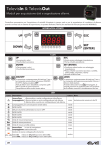
GB
ENGLISH
GENERAL DESCRIPTION
Energy XT PRO is a confiurable and easily customised device.
It has been designed to offer a series of models with varying numbers
of inputs and outputs so that we can always offer our customers the
best solution.
By connecting a base unit to different expansion modules (maximum
of 4), the number of inputs and outputs obtained will satisfy even the
most complex of applications.
Software development tools can be used to modify or create new programs for all types of application thus satisfying our customers’ diverse
needs. In this way, they can develop their own control software and
protect their individual technical knowledge.
All basic control operations can be performed using the graphic LCD,
keyboard and LEDs.
A special support tool helps customers to customise the structure and
text of the user interface simply and easily. MenuMakerPRO can also
handle an unlimited number of
languages, import and export text files and automatically create the
user's guide.
Available models
The EXT PRO family models include the EXTM PRO bases, the EXTE
PRO expansions and the EXTK PRO keyboard.
The /H initial indicate the bases and the expansions with a larger
numer of inputs and outputs (see Tab.1 coloumns 3-6).
The /R initial indicate the bases with RS232, CAN1 and analog outputs.
USER INTERFACE
The operator interacts with the machine using a keyboard with a large,
backlit graphic LCD.
The information provided by the keyboard, which is extremely easily
accessible, enables you to check the status of the machine at any time
and to change its settings, when the need arises.
The keyboard is extremely easy to assemble: you can either rest it
against the panel or enclose it in a wall by making a suitably sized
hole; in the latter case (panel mount), it is also waterproof.
NOTE: EXTM PRO can work without keyboard.
MECHANICAL FEATURES
see table.
TECHNICAL DATA
Common Features
Plastic housing: resin plastic body PC+ABS UL94 V-0
Mount: on DIN-RAIL EN CEI 60715 guide, see MECHANICAL MOUNT
section
Insulation class: 2 (instrument under normal conditions shall not
be accessible).
Operating temperature: -5…60 °C.
Storage temperature: -30…85 °C.
Operating humidity: 10…90 % R.H. (non condensing)
Storage environment humidity: 10…90% R.H. (non-condensing)
Terminals and connectors: extractable, step 5.08, vertical insertion
Data storage: on non-volatile EEPROM memory.
Power supply: 24 V~/c 50/60 Hz
Power: 25VA
Display and Keyboard features
Please refer to ENERGY XT PRO-EXTK PRO Keyboard Instruction Sheet.
TECHNICAL DATA EXTM PRO AND EXTM PRO/R BASE
Dimensions: see table
Digital inputs: 14 inputs 24 Va/c or, on demand, 10 inputs 24 Va/c +
4 inputs 230 Va/c
Analog inputs:
• 4 NTC inputs, with display range from –35 to 150 °C
• 4 inputs configurable to 0-1 V, 0-5 V, 0-10 V, 0-20 mA, 4-20 mA,
NTC with display range from –35 to 150 °C
Digital outputs:
•3 (three) 250 Va 8A relays with exchange contacts SPDT,
•9 (nine) 250 Va 8A relays with normally open contacts SPST N.O.
Analogue outputs (only /R model) : four outputs
• voltage 0-10 Vc up to 20mA with 1% resolution max (end of scale) or
• (on demand) current: 4…20mA on max. load 350Ohm with 1%
resolution max (end of scale)
Connections: quick screw on, diameter of cables max. 2 mm
Connection: on profiled guide
TECHNICAL DATA EXTM PRO/H AND EXTM PRO/HR
Dimensions: see table
Digital inputs: 22 inputs 24 Va/c or, on demand, 14 inputs 24 Va/c +
8 inputs 230 Va/c
Analogue inputs:
• 8 NTC inputs, with display range from –35 to 150 °C
• 8 inputs configurable to 0-1 V, 0-5 V, 0-10 V, 0-20 mA, 4-20 mA,
NTC with display range from –35 to 150 °C
Digital outputs:
• 3, 250 V~ 8A relays with exchange contacts SPDT,
• 17, 250 V~ 8A relays with normally open contacts SPST N.O.
Analogue outputs (only /R model) : four outputs
• voltage 0-10 Vc up to 20mA with 1% resolution max (end of scale) or
• (on demand) current: 4…20mA on max. load 350Ohm with 1% resolution max (end of scale)
Connections: quick screw on, diameter of cables max. 2 mm
Connection: on profiled guide.
TECHNICAL DATA EXTE1(/H) PRO EXPANSION
Please refer to ENERGY XT PRO-EXTE PRO Expansion Instruction Sheet.
MECHANICAL MOUNT
WARNING !
NEVER operate on contacts when the device is powered. The operations must be performed by qualified personnel.
Do not install the instrument in moist and/or dirty places; it is suitable
for operation in environments with an ordinary pollution level.
Leave enough room for air circulation by the cooling holes of the
instrument. The operating temperature range for correct operation is
from –5 to 60 °C.
Base ENERGY XT PRO
Base ENERGY XT PRO is conceived for EN CEI 60715 guide mount; the
electronic device componets are:
•2 equal “SEMIBASES” in thermoplastic (PC+ABS), self-extinguishing
(V0 according to UL94) material: they are connected to each other
and host the control printed circuit boards.
•1 “CAP” in thermoplastic (PC+ABS), self-extinguishing (V0 according
to UL94) material: it provides the electronic device upper protection.
• N.4 “Spring docking devices” to anchor to the EN CEI 60715 GUIDE.
Keyboard
Please refer to ENERGY XT PRO- EXTK PRO Keyboard Instruction
Sheet.
TAB. 1-2-3 MODELS - SERIAL PORTS - MECHANICAL FEATURES
FLASH
(KB)
RAM
(KB)
DIGITAL
INPUTS
ANALOGUE
INPUTS
ANALOGUE
OUTPUTS
RELAY
OUTPUTS**
128+1M
6+512
6+512
6+512
6+512
14
14
22
22
8
8
16
16
4
4
12
12
20
20
EXPANSION
EXTE1 PRO
EXTE1/H PRO
16
32
2
4
4
8
4
4
2
9
15
KEYBOARD
EXTK PRO
16
2
-
-
-
-
MODELS
BASE
EXTM PRO
EXTM PRO/R* 128+1M
EXTM PRO/H 128+1M
128+1M
EXTM
PRO/HR*
Base Mount
For the BASE installation on the EN CEI 60715 GUIDE please operate as
follows:
Set the four "spring docking devices" in rest position (using a screwdriver and levering on the proper slots (see figure 2).
Install the "BASE" on the EN CEI 60715 GUIDE pushing on the "spring
docking devices" that will set to the close position.
Attention:
Once the “BASE” is assembled on the EN CEI 60715 GUIDE, the “Spring
docking devices" must be oriented downwards.
Keboard-base link and cables location
For keyboard wiring please refer to ENERGY XT PRO-EXTK PRO
Keyboard Instruction sheet. To connect the base to the keyboard a 2
m Ethernet-style cable is available: at the ends it is provided with two
8-way Ethernet-style plugs.
The Ethernet-style and the power cables must be wired separately.
ELECTRICAL CONNECTIONS
WARNING !
Never operate on electrical contacts when the machine is on. The
operations must be performed by a qualified personnel.
For a proper connection please pay attention to the following warnings:
• Power supply different from specifications can seriously damage the
system.
• Use cables with a section suitable to terminals used.
• For screw terminal blocks: Unscrew each screw in the block, insert
the cable end and re-screw. Slightly pull the cables at the end of the
operation to check fixing.
• For spring terminal blocks: Insert cable end into the terminal and
check the spring release. Slightly pull the cables at the end of the operation to check fixing. To extract press the switch beneath the terminal
to release the spring.
• Keep probes and digital inputs cables as far as possible from inductive loads and power connections to prevent electromagnetic interference. It is suggested to not place probe cables near other electrical
appliances (switches, meters, etc.)
• Keep cable length as short as possible and do not wind them
around electrically connected parts.
• Do not touch components on boards - it could cause electro-static
sparks.
For all electrical connections please refer to fig.1. For details please
ITALIANO
I
DESCRIZIONE GENERALE
Energy XT PRO è un dispositivo configurabile e personalizzabile.
Dispone una serie di modelli che si differenziano per il numero degli
ingressi e delle uscite in modo da ottenere sempre la miglior soluzione
per il cliente. Collegando una base con i vari moduli di espansione
(massimo 4), è possibile ottenere il numero di ingressi e uscite
richiesto per soddisfare anche le applicazioni più complesse.
Il controllore permette di soddisfare le più svariate esigenze del cliente
attraverso tool software di sviluppo che consentono di generare e
modificare nuovi programmi per qualsiasi tipo di applicazione. In
questo modo il cliente ha la possibilità di diventare autonomo nello
sviluppo del software di controllo preservando così il proprio prezioso
“know how”.
Attraverso un LCD grafico, una tastiera e dei LED è possibile effettuare
tutte le operazioni fondamentali di controllo e gestione dell’applicazione.
Grazie ad un tool di supporto ogni cliente è in grado di personalizzare
la struttura ed i testi dell’interfaccia utente in modo semplice ed intuitivo. MenuMakerPRO permette inoltre una facile gestione di un
numero illimitato di lingue con la possibilità di esportare/importare file
di testo e generare automaticamente il manuale utente.
Modelli Disponibili
I modelli che compongono la famiglia EXT PRO sono le basi, identificate con la sigla EXTM PRO, le espansioni EXTE PRO e la tastiera EXTK
PRO.
La sigla /H indica le basi e le espansioni con un maggior numero di
ingressi e uscite (vedi Tab 1 colonne 3-6).
La sigla /R indica le basi dotate di RS232, CAN1 e uscite analogiche
INTERFACCIA UTENTE
L'utente interagisce con la macchina utilizzando una tastiera con
display LCD grafico, retroilluminato e di grandi dimensioni; dispone
inoltre di tre led e due tasti per il controllo e la programmazione dello
strumento.
ENERGY XT PRO - EXTM PRO (/R, /H, /HR)
refer to ENERGY XT PRO Installation User Manual.
REGULATIONS
The product complies with the following European Union Regulations:
•73/23/CEE European Council regulation and following modifications
•89/336/CEE European Council regulation and following modifications
and complies with the following harmonised standards
• LOW VOLTAGE: EN60335-1 for whatever is applicable
• EMC EMISSION: EN61000-6-3
• EMC IMMUNITY: EN61000 6 1
* R MODELS: RS-232, CAN 1 AND ANALOG OUTPUTS AVAILABLE
H MODELS: BASES AND EXPANSION WITH MORE I/O (SEE TAB. 1 COLUMS 3-6)
** SSR MODELS: NO10, NO11 & NO12 SSR type 100-240Va 600mA max.
SERIAL PORTS
•COM1: RS-485 serial port
•COM2: CAN-BUS 0 serial port
•COM3: RS-232 serial port (only /R
model)
•COM4: CAN-BUS 1 serial port (only /R
model)
SERIALI
•COM1: seriale
•COM2: seriale
•COM3: seriale
/R)
•COM4: seriale
modello /R)
GB
GB
tipo RS-485
tipo CAN-BUS 0
tipo RS-232 (solo modello
tipo CAN-BUS 1 (solo
MECHANICAL FEATURES - CARATTERISTICHE MECCANICHE
Height
Device
Length
Width
Strumento
Lunghezza
Larghezza
Altezza
316
114
80
Base EXTM PRO
Base EXTM PRO/R
316
114
80
Base EXTM PRO/H
316
114
80
Base EXTM PRO/HR
316
114
80
Expansion EXTE1 PRO
159
114
80
Expansion EXTE1 PRO/H 159
114
80
Keyboard EXTK PRO
219
119
32
K b
d EXTK PRO (CUTOUT) 200 L X 103 W
FIG 1a CAP-CALOTTA
FIG 1b HALF-BASES-SEMIFONDELLI
ELIWELL CONTROLS s.r.l.
Via dell'Industria, 15 Zona Industriale Paludi
32010 Pieve d'Alpago (BL) ITALY
Telephone +39 0437 986111
Facsimile +39 0437 989066
Internet http://www.eliwell.it
Technical Customer Support:
Telephone +39 0437 986300
Email: [email protected]
Invensys Controls Europe
An Invensys Company
rel. 3/2006 - GB/I cod. 8FI20009
FIG 2 Spring Docking Devices-Dispositivi di aggancio a molla
I
Le informazioni fornite dalla tastiera, accessibili in maniera molto
intuitiva, permettono di verificare in ogni istante lo stato della macchina e di modificarne, eventualmente, le impostazioni.
La tastiera è disponibile per il montaggio a pannello o per il montaggio a parete praticando un adeguato foro; nel caso di montaggio
a pannello essa offre anche un'elevata protezione all'acqua.
NOTA: EXTM PRO può funzionare anche senza tastiera.
CARATTERISTICHE MECCANICHE
Vedi tabella.
CARATTERISTICHE TECNICHE
Caratteristiche comuni
Contenitore: corpo plastico in resina PC+ABS UL94 V-0.
Montaggio: su guida EN CEI 60715, vedi paragrafo MONTAGGIO
MECCANICO
Classe di isolamento: 2 (in condizioni normali lo strumento NON
deve essere accessibile).
Temperatura di funzionamento: –5…60 °C
Temperatura di stoccaggio: –30…85 °C
Umidità in ambiente di funz.: 10…90% R.H. (non condensante)
Umidità in ambiente di stoccaggio: 10…90% R.H. (non condensante)
Morsetti e connettori: di tipo estraibile, passo 5.08 ad inserzione
verticale
Alimentazione: 24 Va/c, 50/60 Hz.
Potenza: 25 VA.
Caratteristiche Tastiera
Fare riferimento al Foglio Installazione ed Uso ENERGY XT PROTastiera EXTK PRO
CARATTERISTICHE TECNICHE BASE EXTM PRO E EXTM PRO/R
Dimensioni: vedi tabella./
Ingressi digitali: 14 ingressi 24 Va/c oppure, su richiesta, 10 ingressi 24 Va/c + 4 ingressi 230 Va/c
Ingressi analogici:
•4 ingressi NTC con range di visualizzazione da –35 a 150 °C
•4 ingressi configurabili 4-20 mA, NTC con range di visualizzazione
da –35 a 150 °C
Uscite digitali:
•3 relè 250 Va 8A con contatti in scambio SPDT
•9 relè 250 Va 8A con contatti normalmente aperti SPST N.A.
Uscite analogiche (solo versione /R):4 uscite in
• tensione: 0-10 Vc fino a 20mA con 1% di risoluzione max (f.s.)
oppure
• (su richiesta) corrente: 4…20mA con carico max. 350Ohm con 1%
di risoluzione max (f.s.).
CARATTERISTICHE TECNICHE BASE EXTM PRO/H E EXTM
PRO/HR
Dimensioni: vedi tabella.
Ingressi digitali: 22 ingressi 24 Va/c oppure, su richiesta, 14
ingressi 24 Va/c + 8 ingressi 230 Va/c
Ingressi analogici:
•8 ingressi NTC con range di visualizzazione da –35 a 150 °C
•8 ingressi configurabili 4-20 mA, NTC con range di visualizzazione
da –35 a 150 °C
•3 relè 250 Va 8A con contatti in scambio SPDT
•17 relè 250 Va 8A con contatti normalmente aperti SPST N.A.
LIABILITY AND RESIDUAL RISKS
Eliwell Controls s.r.l. shall not be liable for any damages deriving from:
- installation/use other than that prescribed and, in particular, that which
does not comply with safety standards anticipated by regulations and/or
those given herein;
- use on boards which do not guarantee adequate protection against electric shock, water or dust under the conditions of assembly applied;
- use on boards which allow access to dangerous parts without the use of
tools;
- tampering with and/or alteration of the products;
- installation/use on boards not complying with the standards and provisions
of current legislation.
DISCLAIMER
This manual and its contents remain the sole property of Eliwell Controls
s.r.l., and shall not be reproduced or distributed without its authorisation.
Although great care has been exercised in the preparation of this document, Eliwell Controls s.r.l. cannot accept any liability whatsoever connected with its use. The same applies to any person or company involved in the
creation of this manual. Eliwell Controls s.r.l. reserves the right to make any
changes or improvements without prior notice. out giving prior notice and
at any time.
Uscite analogiche (solo versione /R): 4 uscite in
• tensione: 0-10 Vc fino a 20mA con 1% di risoluzione max (f.s.)
oppure
• (su richiesta) corrente: 4…20mA con carico max. 350Ohm con 1%
di risoluzione max (f.s.).
CARATTERISTICHE TECNICHE ESPANSIONE XTE1 PRO(/H)
Fare riferimento al Foglio Installazione ed Uso ENERGY XT PROEspansione XTE PRO.
MONTAGGIO MECCANICO
ATTENZIONE!
Operare sui collegamenti sempre con strumento NON alimentato. Le operazioni devono essere svolte da personale qualificato.
Evitare di montare gli strumenti in luoghi soggetti ad alta umidità
e/o sporcizia: essi, infatti, sono adatti per l’uso in ambienti con un
grado di polluzione ordinaria o normale.
Fare in modo di lasciare aerata la zona in prossimità delle feritoie di
raffreddamento.
Il campo di temperatura ambiente ammesso per un corretto funzionamento è compreso tra –5 e 60 °C;
Base ENERGY XT PRO
La base Energy XT PRO è concepita per il montaggio su guida EN CEI
60715; il dispositivo elettronico è costituito da:
• 2 “SEMIFONDELLI” uguali tra di loro accoppiati dove aloggiano i
circuiti stampati di comando (vedi fig.1b).
• 1 “CALOTTA” che costituisce la protezione superiore del dispositivo
elettronico (vedi fig.1a).
• N. 4 “Dispositivi di aggancio a molla”, presenti sui 2 SEMIFONDELLI,
per l’ ancoraggio alla guida EN CEI 60715.
Tastiera
Fare riferimento al Foglio Installazione ed Uso ENERGY XT PROTastiera EXTK PRO
Montaggio Base
Per l’installazione della BASE su GUIDA EN CEI 60715 procedere
come segue:
Portare i quattro “dispositivi di aggancio a molla” in posizione di
riposo (tramite l’impiego di un cacciavite facendo leva sugli appositi
vani, vedi figura 2) .
Installare quindi la “BASE” sulla GUIDA EN CEI 60715 esercitando poi
pressione sui “dispositivi di aggancio a molla” che si porteranno in
posizione di chiusura.
Nota Bene: A “BASE” assemblata su GUIDA EN CEI 60715 , i
“Dispositivi di aggancio a molla” dovranno essere orientati verso il
basso.
COLLEGAMENTI ELETTRICI
ATTENZIONE!
Operare sui collegamenti elettrici sempre e solo a macchina
spenta. Le operazioni devono essere svolte da personale qualificato.
Per una corretta connessione rispettare i seguenti avvertimenti:
• Alimentazione con caratteristiche diverse da quelle specificate possono seriamente danneggiare il sistema.
• Usare cavi di sezione adatta ai terminali usati.
RESPONSABILITÀ E RISCHI RESIDUI
La Eliwell Controls s.r.l. non risponde di eventuali danni derivanti da:
- installazione/uso diversi da quelli previsti e, in particolare, difformi dalle
prescrizioni di sicurezza previste dalle normative e/o date con il presente;
- uso su quadri che non garantiscono adeguata protezione contro la scossa
elettrica, l’acqua e la polvere nelle condizioni di montaggio realizzate;
- uso su quadri che permettono l’accesso a parti pericolose senza l’uso di
utensili;
- manomissione e/o alterazione del prodotto;
- installazione/uso in quadri non conformi alle norme e disposizioni di legge
vigenti.
DECLINAZIONE DI RESPONSABILITÀ
La presente pubblicazione è di esclusiva proprietà della Eliwell Controls s.r.l.
la quale pone il divieto assoluto di riproduzione e divulgazione se non
espressamente autorizzata. Ogni cura è stata posta nella realizzazione di
questo documento; tuttavia la Eliwell Controls s.r.l. non può assumersi alcuna responsabilità derivante dall’utilizzo della stessa.Lo stesso dicasi per ogni
persona o società coinvolta nella creazione e stesura di questo manuale. La
Eliwell Controls s.r.l. si riserva il diritto di apportare qualsiasi modifica, estetica o funzionale senza preavviso alcuno ed in qualsiasi momento
• Per morsettiera a vite: svitare ciascuna vite della morsettiera, inserire il capo e riavvitare. Alla fine dell’operazione tirare dolcemente
i cavi per controllarne il fissaggio.
• Per morsettiera a molla: inserire il capo del cavo nel morsetto e
verifivcare lo scatto della molla. Alla fine dell’operazione tirare dolcemente i cavi per controllarne il fissaggio. Per estrarre premere
sull’ interruttore posto al di sotto del morsetto che farà rilasciare
la molla.
• Separare per quanto possibile i cavi delle sonde e degli ingressi
digitali dai carichi induttivi e dalle connessioni di potenza per evitare interferenze elettromagnetiche. Evitare che i cavi delle sonde
siano posizionati in prossimità di altre apparecchiature elettriche
(interruttori, contatori, ecc.)
• Ridurre la lunghezza dei collegamenti per quanto possibile ed evitare di avvolgerli a spirale attorno a parti elettricamente connesse.
E’ consigliato utilizzare cavi schermati per le connessioni delle
sonde.
• Evitare di toccare i componenti elettronici sulle schede per non
provocare scariche elettrostatiche.
Per i tutti collegamenti elettrici fare riferimento alla figura 1. Per i
dettagli fare riferimento al manuale d’uso.
Collegamento Base - Tastiera
Per i morsetti presenti sulla tastiera fare riferimento al Foglio
Installazione ed Uso ENERGY XT PRO- Tastiera EXTK PRO.
Per la connessione tra base e tastiera è in dotazione un cavetto
“tipo Ethernet” lungo 2 metri, recante alle estremità due plug “tipo
Ethernet” ad 8 vie. È necessario fare in modo che il cavetto “tipo
Ethernet” sia cablato separatamente dai cavi di potenza.
NORMATIVE ED USO
Il prodotto risponde alle seguenti Direttive della Comunità Europea:
• Direttiva del consiglio 73/23/CEE e successiva modifiche
• Direttiva del consiglio 89/336/CEE e successive modifiche
e risulta conforme alle seguenti Norme armonizzate
• LOW VOLTAGE: EN60335-1 per quanto applicabile
• EMC EMISSION: EN61000-6-3
• EMC IMMUNITY: EN61000-6-1
Dip switches have to be set in
order to:
• Enable or DISABLE the
CANBUS network final resistor
• Specify the LSB network
(RS-485) address of XT PRO
The address of the EXTM PRO is
unique for both serial lines
(COM1 and COM3).
The address is a byte formed by
2 parts:
• Device family (nibble MSB
“upper part”): EEPROM
parameter called FAA_ADDRESS
• Device address (nibble LSB
“low part”): selectable by means
of dip switches 2-3-4
Dip switch # 1
•ON: terminal resistor enabled
•OFF: terminal resistor
DISABLED
Dip switch # 2-3-4
•ON: value =1
•OFF: value =0
Examples
• If dip 2 ON, dip 3 OFF, dip 4
OFF, then LSB=1(the binary number is 001 if read from right to
left)
• If dip 2 ON, dip 3 ON, dip 4
OFF, then LSB=3 (the binary
number is 011 if read from right
to left)
I/O
std
see
fig 4
upper
view
base
board
I/O
extended
see
fig 4
I dip switch hanno lo scopo di:
• attivare la resistenza di terminazione di rete CANBUS
• indicare la parte “bassa” (LSB)
dell’indirizzo di rete RS-485
dell’XT PRO.
L’indirizzo del dispositivo EXTM
PRO è unico per le due seriali
COM1 e COM3.
L’indirizzo è un byte costituito da
2 parti:
• famiglia del dispositivo (nibble
MSB “parte alta”): parametro in
EEPROM denominato
FAA_ADDRESS
• indirizzo del dispositivo (nibble
LSB “parte bassa”):
selezionabile tramite i dip switch
2-3-4
I/O
LEGENDA
dip switch 1
•ON: resistenza attivata
•OFF: resistenza NON attivata
dip switch 2-3-4
•ON: valore=1
•OFF: valore=0
Esempi:
•se dip 2 ON, dip 3 OFF, dip 4
OFF allora LSB=1 (in binario 001
letto da dx a sx)
•se dip 2 ON, dip 3 ON, dip 4
OFF allora LSB=3 (in binario 011
letto da dx a sx)
terminal
address
resistor
resistenza di
PLEASE NOTE:
• TTL port is logged
in vertical position
terminazione indirizzo
ON
ON
1 2 3 4
COM4
2 3 4
TTL
ON
ON
2 3 4
1 2 3 4
DIP
SWITCH
IIC
BUS
NOTA:
• porta TTL
posizionata
verticalmente (in
piedi)