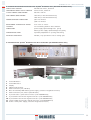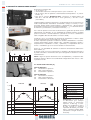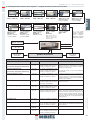
1
8XX
ENG-ITA
SDS© Drive
Drive - Instruction Manual
Motorizzazione - Manuale
808-000-000
q DC-PWM
q AC-VVVF BRUSHLESS
q AC-VVVF BRUSHLESS PLUS
E 18 December 2009
808-000-000 SDS© rel.3 • Edition 18 December 2009
Clausola di riservatezza
ITALIANO
The software/hardware “Sematic Drive System©” and all the relevant information, ideas, concepts and know-how are
confidential and the exclusive property of Sematic.
All information relevant to this instruction manual and any other support supplied by Sematic must be kept confidential and proprietary to Sematic and shall not to be copied or reproduced in any form whatsoever.
Any information contained in the “Sematic Drive System©” shall not be disclosed to anyone, without Sematic’s written
consent apart from authorized representatives employed by the user which commits itself to the confidentiality clause.
The Company that makes use of the Sematic Drive System©, binds itself not to use confidential informations owned by
Sematic and not to compile or reingineer the Sematic Drive System© and any information in it contained.
ENGLISH
Confidentiality agreement Disclaimer
Il sistema software/hardware “Sematic Drive System©” e le informazioni ivi contenute, le idee, i concetti e il know-how,
sono confidenziali e di proprietà della Sematic.
Le informazioni contenute in questo manuale ed ogni altro supporto fornito dalla Sematic devono essere mantenuti confidenziali e di proprietà della Sematic e non possono essere copiati o riprodotti in alcuna forma.
Ogni informazione contenuta nel sistema “Sematic Drive System©” non potrà essere rilasciata ad alcuno, senza l’assenso scritto della Sematic, al di fuori del personale autorizzato dipendente della società che si fa carico dell’impegno
di riservatezza.
La società che utilizza il sistema “Sematic Drive System©”, si impegna a non tentare di utilizzare informazioni confidenziali della Sematic ed a non ricompilare o reingenerizzare il sistema “Sematic Drive System©” e qualsiasi informazione ivi contenuta.
Please dispose of the
controller correctly.
Bitte entsorgen Sie das
Türsteuergerät auf korrekte Weise.
Prière de distinguer
correctement le controller.
cod. 1020211-263
Rogamos diferenciar la controla
corectamente.
© Sematic Italia Spa. All rights reserved.
Sematic regards all the information contained in this instruction manual to be correct at the time of printing. This information does not constitute any obligation to Sematic and can be modified without
prior notification. Sematic cannot be held responsible for any possible damages or claims caused to items or persons due to errors or misunderstandings within the contents of this instruction manual.
© SEMATIC • All rights reserved.
Changes can be made without notice.
Si prega di differenziare
correttamente il controller.
© Sematic Italia Spa. Tutti i diritti sono riservati.
Sematic ritiene che le informazioni contenute in questo documento alla data della pubblicazione siano corrette. Tali informazioni non costituiscono impegno per la Sematic e possono essere modificate senza preavviso. Sematic non si ritiene responsabile per eventuali danni causati a persone o cose a seguito di inesattezze o errate interpretazioni relative al contenuto del presente manuale.
1
ITALIANO
ENGLISH
808-000-000 SDS© rel.3 • Edition 18 December 2009
© SEMATIC • All rights reserved.
Changes can be made without notice.
sematic.com
2
Sematic Group:
we take care of
your integrated solutions!
Gruppo Sematic:
ci preoccupiamo della vostra
soluzione integrata!
COMPONENT SYSTEMS
• Automatic lift doors
• Frame and frameless glass doors
• Enhanced car door operator solutions
• Complete cabins
• Car Frames
• Custom integrated packages
• Special lift doors, cabins and car frames
COMPONENTI
• Porte automatiche
• Porte in vetro totale e vetro intelaiato
• Soluzioni avanzate per operatori di cabina
• Cabine complete
• Arcate
• Pacchetti integrati di componenti
• Porte, cabine e arcate speciali
ELEVATOR SYSTEMS & SUBSYSTEMS
• Rope traction elevators
• Machineroomless roped elevators
• Modular hydraulic elevators
• Hydraulic elevators
• Panoramic elevators
• Hospital elevators
• Special executions
SISTEMI & SOTTOSISTEMI PER ASCENSORI
• Ascensori a fune
• Ascensori a fune senza sala macchina
• Ascensori modulari idraulici
• Ascensori idraulici
• Ascensori panoramici
• Ascensori per ospedali
• Esecuzioni speciali
808-000-000 SDS© rel.3 • Edition 18 December 2009
PREFACE
pag.
5
2
WHAT IS THE SEMATIC DRIVE SYSTEM©
2.1 Speed profiles
pag.
7
3
GENERAL FEATURES
3.1 Technical information Sematic Drive System© (DC-PWM and AC-VVVF Brushless)
3.2 Sematic Drive System© Door Controller (DC-PWM and AC-VVVF Brushless)
3.3 Technical information Sematic Drive System© Brushless Plus (AC-VVVF Brushless Plus)
3.4 Sematic Drive System© Brushless Plus Door Controller (AC-VVVF Brushless Plus)
pag.
8
4
SIGNALS TO/FROM THE DOOR CONTROLLER
4.1 Sematic Drive System© (DC-PWM and AC-VVVF Brushless) connections
4.2 Sematic Drive System© (AC-VVVF Brushless Plus) connections
4.3 Sematic Drive System© set-up and incoming/outgoing signals from the door controller
4.4 Detector/Photocell/Barriers: Signal-Only Connection to the Door Controller (Direct Connection)
4.5 Detector/Photocell/Barriers: Complete Connection to the Door Controller
pag.
10
5
INSTRUCTIONS WITHOUT HANDSET
Display in Automatic and Manual Mode
5.1 Automatic Mode “AUTO”
5.2 Manual Mode “MAN”
5.3 Programming Mode “PROG”
5.4 Verify the correct working of the controller SDS
pag.
14
6
FUNCTIONS AVAILABLE
pag.
6.1 Reversing
6.1.1 Reversing System Force Setting (Param. Code 09)
6.1.2 Reversing system offset
6.2 Reversing System choice: INTERNAL or EXTERNAL (Param. Code 00)
6.3 Main Lift Controller Test
6.3.1 Main Lift Controller Test (When moving) [Default setting]
6.3.2 Main Lift Controller Test (When moving + Parking)
6.3.3 No MLC Signal
6.3.3.1 Instant Stop
6.3.3.2 Low Speed to Stop
6.3.3.3 Low Speed Cycle
6.3.4 Main Lift Controller Input Alarm (Param. Code 03)
6.4 Kn Input (Param. Code 04)
6.4.1 Default type
6.4.2 Limited door reversal
6.4.2 Safety edge
6.5 Car Door Locking Device (USA = Restrictor) (Param. Code 05)
6.6 Full or Framed Glazed and Heavy Paneled Doors (GLASS AND HEAVY DOORS) (Param. Code 06)
6.7 Aux Output Relay (Param. Code 07)
6.7.1 Space Percentage
6.7.2 Gong While Opening
6.7.3 Thermic alarm signal
6.8 Forced Closing [Nudging]
6.9 Fire Fighting (Param. Code 19)
6.10 Double TB
6.11 EOD (Emergency Opening Device) and timeout (Param. Code 20)
6.12 Protective Device Logic Kn (Param. Code 21)
6.13 Motor Rotation During Closing (Param. Code 22)
6.14 Motor Type
6.15 Closing parking Mode (Param. Code 25)
6.15.1 Closed skate parking
6.15.2 Opened skate parking
6.15.3 PM activation Delay
6.15.4 PM Opening space
6.15.5 PM position error
17
ENGLISH
1
© SEMATIC • All rights reserved.
Changes can be made without notice.
see www.sematic.com for latest release
Index
3
808-000-000 SDS© rel.3 • Edition 18 December 2009
© SEMATIC • All rights reserved.
Changes can be made without notice.
ENGLISH
6.15.6 PM position control
6.16 Skate Type (Param. Code 26)
6.17 AUX Input (Param. Code 32)
6.17.1 Disables (default)
6.17.2 % Partial Reopening
6.18 IM (reversing motion) signal type (Param. Code 34)
6.18.1 IM pulse
6.18.2 IM continuous (default)
6.18.3 Monostable pulse
6.19 Alarms
4
7 TRIAL OPERATIONS BEFORE SETTING AT WORK
7.1 Self-learning cycle
7.2 Self-learning cycle with the door controller only (without using the handset)
pag.
23
8 INSTRUCTIONS WITH THE HANDSET
8.1 Handset (optional)
8.2 User Handset menus and submenus
8.3 Self-learning cycle activation by means of the handset
8.4 Reversing System Force setting by means of the handset
8.5 Setting reversing system offset with the keypad
8.6 Speed Profile and High Speed adjustments by means of the Handset
8.6.1 Option “Fast settings”
8.7 Option “Set Factory Default”
8.8 Option “Reserved Area”
8.9 Option “Advanced Settings”
8.9.1 Option “Opening Parameters”
8.9.2 Option “Closing Parameters”
8.9.3 Option “Reversing System Space”
8.9.4 Option “Serial Bus”
8.9.5 Option “Change Password”
8.9.6 Option “Save set data”
8.9.7 Option “Recall set data”
8.9.8 Option “Data Download”
8.9.9 Option “Data Upload”
8.9.10 Option “Smooth reopening”
pag.
24
9
GENERAL OPTIONS
9.1 Reversing System Setting by means of the Handset
9.2 Kn input Activation by means of the Handset
9.3 Activation of the Main Lift Controller Test by means of the Handset
9.4 Activation of the Main Lift Failure by means of the Handset
9.5 Main Lift Controller Alarm - (MLC Input Alarm)
9.6 Activation of the Car Door Locking Device setting by means of the Handset
9.7 Activation of the Glazed and Heavy Paneled Doors setting by means of the Handset
9.8 AUX Output Relay setting by means of the Handset
9.9 Fire Fighting Option setting by means of the Handset
9.10 EOD Timeout setting by means of the Handset
9.11 Protective Device Logic Kn setting by means of the Handset
9.12 Closing Rotation by means of the Handset
9.13 Motor type by means of the Handset
9.14 Closed parking Mode by means of the Handset
9.15 Skate type setting by means of the Handset
9.16 AUX input setting by means of the Handset
9.17 IM signal type setting by means of the Handset
pag.
31
10
MAINTENANCE MENU - DIAGNOSTICS AND ALARM MANAGEMENT
10.1 Consulting the Maintenance Menu with the Handset
pag.
36
11
CONTROLLER SOFTWARE UPGRADE
pag.
37
12
DOOR OPERATOR MAINTENANCE
pag.
37
13
SPARE PARTS
pag.
37
808-000-000 SDS© rel.3 • Edition 18 December 2009
This manual has been drafted taking into account that the Company installing genuine Sematic products will comply
with the following necessary requirements:
• personnel responsible for the installation and/or maintenance of the doors must be familiar with the General and
Specific regulations in force on the subjects of work safety and hygiene (89/391/CEE - 89/654/CEE - 89/656/CEE);
• personnel responsible for the installation and/or maintenance must be familiar with the Sematic product and must
have been trained by Sematic or by an authorized Sematic agent;
• installation equipment used must be in good working order with all measuring instruments calibrated (89/655/CEE).
ENGLISH
1 PREFACE
Sematic:
• undertakes to update the present manual and send the customer copies of all new updates together with material;
• within its continuous product improvement policy, reserves the right to make changes to the designs and materials
of its products. Sematic will give an agreed reasonable time to all its customers to allow them to adapt to the new
changes their complementary current constructions;
• guarantees a good performance only of the original parts sold directly and correctly installed.
Therefore:
parts manufactured and/or added to the Sematic product without his direct control, or non-original parts based upon
a Sematic design (even if supplied by authorised agents) cannot be considered under guarantee since the following conditions have not been ensured:
1
2
3
4
Quality control of raw material supply
Process control
Product control
Conformity tests according to Sematic specifications
Furthermore, Sematic:
• guarantees the performance life of its products only if correctly stored (indoors storage at temperatures ranging
between -10 and +60 °C out of direct sunlight) and correctly installed;
• guarantees the perfect performance of the products installed in environments with temperatures between -10 and
+60 °C and with a non-condensing, relative humidity level included between 20% and 80%.
(Special note: for temperatures and humidity rates outside these ranges, please consult our Technical Dept.)
The present document has been drafted in accordance with the following EU Directives:
• 98/37/CE Machinery Directive and subsequent modifications (when applicable)
• 95/16/CEE Lifts Directive
• 93/68/CEE Markings
• 90/269/CEE Heavy loads handling
• Noise (Acoustic emission) 86/188/CEE modified according to Directive 98/24/CEE
• Electromagnetic compatibility 89/336/CEE
(+) → for motors:
• B105AAAX01 - 1 Nm Dc (B105AABX01 - 1Nm Dc sur demande)
• B105AAAX02 - 2Nm Dc (B105AABX02 - 2Nm Dc sur demande)
• B105AALX - Dc - GR63x55-SG120
• B105AANX - Dc - GR63x25-SG80K
• B105AAPX - IP54 - DC GR63x25-SG80K
• B105AAQX - IP54 - DC GR63x55-SG120K
• B105AAIX - Brushless - BG62x30-SG80K
• B105AAJX - Brushless - BG62x60-SG120
• B105AAHX - Brushless - BG62x60-PLG60
• B105AAGX - Brushless
• B105AATX - IP54 Brushless BG62x30-SG80K
• B105AARX - IP54 Brushless BG62x60-SG120K
• B105AADX - Dc
(*) → only for motors:
• B105AAIX - Brushless - BG62x30-SG80K
• B105AAJX - Brushless - BG62x60-SG120
• B105AALX - Dc - GR63x55-SG120
• B105AANX - Dc - GR63x25-SG80K
© SEMATIC • All rights reserved.
Changes can be made without notice.
and with the following particular standards:
• EN81; (+)
• AS1735; (+)
• EN12015/EN12016; (+)
• EN13015; (+)
• ASME A17.1 :2000; (*)
• UL508C; (*)
5
808-000-000 SDS© rel.3 • Edition 18 December 2009
ENGLISH
Taking into account, during all project planning, the Risk Assessments relating to:
A. RISKS OF MECHANICAL HAZARDS
• Squeezing during operations
• Squeezing after Trapping caused by friction (glass panels)
• Cuts caused by sharp edges, or static sharp pieces
B. RISKS OF ELECTRICAL HAZARDS
• Persons in contact with energized parts (direct contact)
• Persons in contact with parts that become energized due to a fault (indirect contact)
C. RISKS OF OVERHEATING
D. RISKS GENERATED BY NOISE
E. RISKS GENERATED BY VIBRATION
© SEMATIC • All rights reserved.
Changes can be made without notice.
F. RISKS GENERATED BY MATERIALS AND SUBSTANCES
6
808-000-000 SDS© rel.3 • Edition 18 December 2009
The System consists of:
• a Car Door Operator (1)
• a microprocessor-based Door Controller (2)
• DC (brushed or brushless type) Motor (3) with feedback signals (4).
• A 500 VA or 750 VA 230-400 Vac ± 10% (primary) and 36 Vac ± 10%
(secondary) transformer, only for Brushless Plus controller version.
1
ENGLISH
2 WHAT IS THE SEMATIC DRIVE SYSTEM©
The Sematic Drive System© automatically controls the opening and closing
of the lift doors, monitoring the timing, current variations, speeds (high,
low, acceleration and deceleration curves), various safety systems (reversing system, Limited Door Reversal etc.) and faults (high voltage, signal
failure, ...).
2
There are two independent speed curve profiles for the opening and closing
cycles (5) which can be modified by means of the door controller push buttons or by means of the Sematic handset (an optional 8 digit keypad and
display accessory which can be connected to the card by an RJ45 plug).
2
The handset (6) is a key pad that allows viewing and modification of the
function parameters stored in the controller.
It is important to use the Sematic handset for installation or maintenance,
as it enables viewing and/or variation of the controller parameters, systems,
and operation errors.
3
Furthermore, it is possible to use the Sematic handset directly from the inside of the car (7).
Making it possible to monitor and modify the door operating parameters
from a completely safe position, and also to control the movement of the
coupled car and landing doors during their effective operating cycle.
4
5
Note: the pictures on this document are examples only; real components
appearances may differ according to supplied configuration of door operator
and motor.
2.1 Speed profile (8)
Opening Cycle
01
Opening acceleration
02
Opening hight speed
03
Opening deceleration
7
6
Closing Cycle
C1
Closing acceleration
C2
Closing hight speed
C3
Closing deceleration
8
OPENING
KEY
CLOSING
V (m/s)
Ka Door opening
Kc Door closing
Kc
La
O1
C1
C2
C3
DOOR CLOSED
O3
La
Open limit
Lc
Close limit
Closing cycle
Active reversing system
Opening cycle
t (s)
Warning: for big size doors
(for example total moving
mass over 400 Kg) it’s advisable not to modify the pre-set
closing high-speed factory
default, according to EN81
standard
(closing
kinetic
energy limitations).
© SEMATIC • All rights reserved.
Changes can be made without notice.
Ka
O2
DOOR OPENED
DOOR CLOSED
MAX.
1.1 m/s
Lc
7
808-000-000 SDS© rel.3 • Edition 18 December 2009
ENGLISH
3. GENERAL FEATURES
3.1 Technical information Sematic Drive System© (DC-PWM and AC-VVVF Brushless)
MAIN SUPPLY VOLTAGE
90-290 Vac (115 V-20%, 230V+26%), 50-60 Hz
TYPICAL POWER CONSUMPTION
200 VA
PEAK POWER CONSUMPTION
300 VA
MOTOR OVERLOAD PROTECTION
@In <15 minutes
@2In <3 minutes
OPERATIONAL TEMPERATURE RANGE
from -10°C to +60°C
HUMIDITY
non-condensing between 20% and 80%
PROTECTION
rapid cartridge fuse [5x20, 4 A]
battery fuse [5x20, 8 A]
PERFORMANCE SPEED
separately adjustable for opening and closing
REVERSAL SENSITIVITY
Variable, only operational on door closing cycle
3.2 Sematic Drive System© Door Controller (DC-PWM and AC-VVVF Brushless)
3
1
2
5
4
7
© SEMATIC • All rights reserved.
Changes can be made without notice.
6
8
8
9
10
11
1
Power ON button
2
Power OFF button
3
Display
4
Manual mode buttons
5
RJ45 Connection port (Handset)
6
6 poles motor and auxiliary EOD battery power supply connector (cod. E066AARX-05)
7
RJ45 Connection port (Motor optical Encoder)
8
4 poles detector / photocells connector (cod. E066AARX-06)
9
6 poles Main Lift Controller signals connector (cod. E066AARX-03)
10 6 poles Main Lift Controller signals connector (cod. E066AARX-04)
11 10 poles Main Lift Controller signals connector (cod. E066AARX-07)
808-000-000 SDS© rel.3 • Edition 18 December 2009
MAIN SUPPLY VOLTAGE
230-400 Vac ±10%, 50-60 Hz
CONTROLLER POWER SUPPLY VOLTAGE
36 Vac ±10%, 50-60 Hz
TYPICAL POWER CONSUMPTION
500 VA o 750 VA
PEAK POWER CONSUMPTION
ENGLISH
3.3 Technical information Sematic Drive System© Brushless Plus (AC-VVVF Brushless Plus)
1000 VA (for 500 VA transformers)
1400 VA (for 750 VA transformers)
MOTOR OVERLOAD PROTECTION
@In <15 minutes
@2In <3 minutes
OPERATIONAL TEMPERATURE RANGE
from -10°C to +60°C
HUMIDITY
non-condensing between 20% and 80%
PROTECTION
power supply rapid cartridge fuse [30 A]
battery power supply rapid cartridge fuse [30 A]
PERFORMANCE SPEED
separately adjustable for opening and closing
REVERSAL SENSITIVITY
Variable, only operational on door closing cycle
3.4 Sematic Drive System© Brushless Plus Door Controller (AC-VVVF Brushless Plus)
3
1
2
5
4
12
7
8
9
10
1
Power ON button
2
Power OFF button
3
Display
4
Manual mode buttons
5
RJ45 Connection port (Handset)
6
Motor and auxiliary EOD battery power supply (controller integrated connector)
7
RJ45 Connection port (Motor optical Encoder)
8
4 poles detector / photocells connector (cod. E066AARX-06)
9
6 poles Main Lift Controller signals connector (cod. E066AARX-03)
10 6 poles Main Lift Controller signals connector (cod. E066AARX-04)
11 10 poles Main Lift Controller signals connector (cod. E066AARX-07)
12 36 Vac + Gnd power supply (controller integrated connector)
11
© SEMATIC • All rights reserved.
Changes can be made without notice.
6
9
808-000-000 SDS© rel.3 • Edition 18 December 2009
ENGLISH
4 SIGNALS TO/FROM THE DOOR CONTROLLER
4.1 Sematic Drive System© (DC-PWM and AC-VVVF Brushless) connections
© SEMATIC • All rights reserved.
Changes can be made without notice.
4.2 Sematic Drive System© (AC-VVVF Brushless Plus) connections
10
808-000-000 SDS© rel.3 • Edition 18 December 2009
ENGLISH
4.3 Sematic Drive System© set-up and incoming/outgoing signals from the door controller
cod. B105AAAX01
IP23 - 1 Nm Dc
cod. B105AABX01
IP54 - 1Nm Dc
cod. B105AAAX02
IP23 - 2Nm Dc
cod. B105AABX02
IP54 - 2Nm Dc
cod. B105AANX IP54 (Option) - Dc
GR63x25-SG80K
cod. B105AAPX
cod. B105AAIX IP54 (Option)
Brushless
BG62x30-SG80K
cod. B105AATX
cod. B105AAJX IP54 (Option)
Brushless
BG62x60-SG120
cod. B105AARX
cod. B105AAHX IP54 (Option)
Brushless
BG62x60-PLG60
cod. B105AAGX
IP65
Brushless
cod. B105AADX
IP54 - EEx
Dc
cod. B105AALX IP54 (Option) - Dc
GR63x55-SG120
cod. B105AAQX
= with these
motors the complete
Sematic
Drive
System©
operator acquires
the IP43 protection.
Note: this motor is
available only for SDS
Brushless Plus © controller.
EOD Kit (option)
Tk - Tk
Main Lift Controller
Safety chains
Photocells
or Detectors
INCOMING SIGNALS FROM THE DOOR CONTROLLER
Opening control Ka
Connector Pins
Connector pins
5 - 15
(coming from the Main Lift Controller)
Closing control Kc
Connector pins
3 - 15
(coming from the Main Lift Controller)
Contact Type & Normal State
Notes
These connections require dry When the Door Controller is installed on a
(voltage free) contacts
Front & Rear entrance car, it is important that
(contact open when inactive)
the opening and closing commands have no
common contacts between the two doors.
These connections require dry
Grounded
Wire
Highly
(voltage free) contacts. (contact Shielded,
Recommended
open when inactive)
Forced closing control at
low speed Kb
Connector pins
15 - 22
These connections require dry The main lift controller may signal the forced
(voltage free) contacts
closing when the photocell (or similar device)
(contact open when inactive)
shall be made inoperative due to a failure, or
after several door closing failures.
Re-Opening control Kn
Connector pins
15 - 23
These connections require dry See sections 4.1.1 & 4.1.2. for the connection
(voltage free) contacts. (both to the door controller
logics available)
Fire-Fighting Contact Kff
Connector pins
15 - 39
These connections require dry See section 6.9
(voltage free) contacts. (contact
open when inactive)
Contact K2TB
Connector pins
15 - 41
These connections require dry This signal allows the door controller to reco(voltage free) contacts.
gnize different door opening widths in the
(contact open when inactive)
same lift installation.
Given this signal, the opening and closing
operations are carried out referring to an
alternative TB (door width recorded by an
additional self-learning cycle).
Encoder Signals
Connector RJ45 Factory prewired
(A)
connector
Contact KEOD
Connector pins
15 - 40
Handset (Optional)
RJ45 connector
(B)
Auxiliary Contact Kaux
Connector pins
15 - 42
These connections require dry This connection is to signal the use of the
(voltage free) contacts. (contact Sematic E.O.D. Emergency Opening Device to
open when inactive)
the Door controller
© SEMATIC • All rights reserved.
Changes can be made without notice.
Signal
These connections require dry Not yet implemented
(voltage free) contacts. (contact
open when inactive)
11
ENGLISH
808-000-000 SDS© rel.3 • Edition 18 December 2009
Note: Sematic Drive System© controller may be used also with incoming signal from the Main Lift Controller with voltage range between 6 and 24 Vdc.
To use this feature:
• Remove the shunt between 37-38 connector pins
• Connect the 38 connector pin at the 0V DC external incoming signal Power supply
OUTGOING SIGNALS FROM THE DOOR CONTROLLER
Signal
Connector Pins
Contact Type & Normal State
Notes
Opening limit switch contact La
Connector pins
16 - 17
These connections provide dry The contact is open when the door is fully
open.
(voltage free) contact.
Contact rating: 3A 250Vac 30Vdc
Closing limit switch contact Lc
Connector pins
18 - 19
These connections provide dry The contact is open when the door is fully closed.
(voltage free) contact.
Contact rating: 3A 250Vac 30Vdc
Reversing system signal IM
Connector pins
2-4
These connections provide dry This signal is generated by dry (voltage free)
(voltage free) contact.
Form C contacts (relay within the Door
Controller) and is activated only when either a
mechanical obstacle (excessive force) pre(contact normally closed)
vents the doors from closing, or a signal is
received from an external safety device that is
connected to the door controller.
It is used to signal the main lift controller to
interrupt the door close command and give a
(contact normally open)
door open signal. Contact rating: 3A 250Vac
30Vdc
Connector pins
35 - 34
These connections provide dry These contacts can be used to signal that a
(voltage free) contact.
particular (pre-set) door opening distance has
been achieved, or as a Gong or Buzzer while
the door is opening or as a Thermic alarm
(contact normally open)
signal.
Contact rating: 3A 250Vac 30Vdc.
Connector pins
1-4
Auxiliary Output Signal AUX
Connector pins
35 - 36
(contact normally closed)
Motor
Connector pins
43 - 44 - 45
Factory-prewired connector
Acoustic alarm
(BUZZER)
-optional-
Connector pins
15 - 21
These connections provide a
24Vdc, 100ma contact.
Contact is open when not active.
• For the Door Operator mechanical installation refer to the “Installation and maintenance of Sematic doors” manual.
• The door controller is supplied already mounted on the operator. All the connections between the door controller and
the motor are pre-wired at Sematic. In order to prevent possible damage to the wiring cables by coming into contact
with the drive belt, they are fixed to the header as shown in the following image (only for B105AAIX, B105AAJX,
B105AAKX, B105AANX and B105AALX).
c
Sematic Drive System
. FOR FURTHER INFORMATIONS
REFER TO THE USER'S GUIDE
..
. FUR WEITERE
INFORMATIONEN
..
BENUTZEN SIE BITTE DAS HANDBUCH
. PER MAGGIORI INFORMAZIONI
EMC PROTECTION
RIFERIRSI AL MANUALE UTENTE
KEEP CLOSED!
GESCHLOSSEN HALTEN!
LEGENDA
MANTENERE CHIUSO!
La - OPENING
. . LIMIT
Lc - CLOSING. .LIMIT
TURE AUF-ENDKONTAKT
Kff
39
Kaux
Kn
Kb
Kc
DETECTOR/
Gnd
33
IN
32
PNP N/O
31
(OPTIONAL)
PHOTOCELL
23
41
RJ45
(B)
22
KEOD
Ka
+24V
42
K2TB
40
3
NC
30
TURE ZU-ENDKONTAKT
LIMITE APERTURA
Ka - DOOR. OPENING
RELAY
.
LIMITE CHIUSURA
Kc - DOOR CLOSING RELAY
OFFNUNGS-RELAIS
SCHLIESS-RELAIS
RELE' DI APERTURA
K2TB - DOUBLE TB RELAY
38
RELE' DI CHIUSURA
Kaux - AUXILIARY RELAY
ZUSATS-RELAIS
DOPPELTE TB-RELAIS
5
RELE' AUSILIARIO
RELE' DI DOPPIO TB
37
15
21
COMMON
+24 V
Kff - FIREFIGHTING RELAY
FEUERSHUTZ-RELAIS
NO
36
AUX
RJ45
(A)
34
RELE' DI FIREFIGHTTING
E
35
KEOD - E.O.D. ACTIVATION RELAY
E.O.D. ACTIVIERUNG-RELAIS
ENCODER
NC
RELE' DI ATTIVAZIONE E.O.D.
19
Kb - DOOR CLOSING RELAY IN SLOW SPEED
OUTPUT
Lc
SCHLIESS-RELAIS KLEINE GESCHWINDIGKEIT
18
RELE' DI CHIUSURA IN BASSA VELOCITA'
17
La
NO
2
IM
4
cyl.5x20
NC
1
110V-230V
0
FUSE
250V 8A
Kn - PHOTOCELL / NUDGING
16
FUSE
250V 4A
N
Gnd
+
Battery
24 V
-
(OPTIONAL)
cyl.5x20
IM - REVERSE MOTION RELAY
REVERSIERUNGS-RELAIS
RELE' DI INVERSIONE DI MOTO
28
45
SELF - SELF LEARNING CYCLE BUTTON
GND
44
F
43
M
(PUSH AT INSTALLATION)
..
TASTE FUR SELBSTLERNZYKLUS
(BEI INSTALLATION DRUCKEN)
MOTOR
..
TASTO PER CICLO DI AUTOAPPRENDIMENTO
(PREMERE ALLA INSTALLAZIONE)
COD. H147AASX
© SEMATIC • All rights reserved.
Changes can be made without notice.
Note: In case of motor replacement be sure to bind the excess cable lenght as above pictured, to avoid any contact of the motor cable with the driving belt.
12
• Warning: to avoid possible induced currents within field wiring, it is recommended to shield the Ka and Kc signals
(connector pins 3, 5 and 15) with grounded, shielded cables.
• Changes made to the factory wiring length or position can damage the EMC system characteristics and is not recommended.
4.4 Detector/Photocell/Barriers: Signal-Only Connection to the Door Controller (Direct Connection)
This connection requires a dry (voltage free) external relay contact connected to the Door Controller Connector pins 15
& 23.
If desired, it is possible to connect the single output signal from a photocell (or similar device) formed by a voltage free
contact, so that the door controller will directly receive the command to re-open.
NOTE: This connection method does not provide for Door Controller interaction with Fire Service Operation. The Main
Lift Controller must be arranged to either interrupt the signal from the Detector/Photocell/Barrier, or to interrupt the
power supply of the Detector/Photocell/Barrier as required under Fire Service Operation (Fire Fighting).
ENGLISH
808-000-000 SDS© rel.3 • Edition 18 December 2009
The photocell (or similar device) has therefore an independent power supply and sends only its outgoing signal to the
Sematic Drive System© controller.
Reopening is operated according to the REVERSING SYSTEM, LIMITED DOOR REVERSAL EFFECT and PROTECTIVE DEVICE LOGIC settings (see sections 6.2, 6.3 and 6.12).
4.5 Detector/Photocell/Barriers: Complete Connection to the Door Controller
Complete Connection means that the device draws its power supply from and sends the re-open signal directly and only
to the Sematic Drive System© controller.
It is possible to have the complete connection of detectors or photocells with a 24 Vdc max 100 mA supply and a PNP
N/O or N/C output, through the connector pins:
GND
GND
OUT PNP N/O - N/C
+ Vdc
33 GND
ground connector pin
32 IN
PNP N/O or N/C signal from
detector/photocell/barrier
NC +24 Vdc IN GND
30
32 33
31
31 +24 Vdc Vdc power supply to detector/
photocell/barrier
TX
Example of photocells/barriers with transmitter and
receiver
connected
between themselves through the dummy free connector pin 30.
30 NC
RX
dummy free connector pin
(it can be used as a dummy connector for connection between the
detectors system components).
© SEMATIC • All rights reserved.
Changes can be made without notice.
The operating reopening modes depend upon the setting of the REVERSING SYSTEM, LIMITED DOOR REVERSAL EFFECT
and PROTECTIVE DEVICE LOGIC settings (see section 6.2, 6.3 and 6.12).
13
808-000-000 SDS© rel.3 • Edition 18 December 2009
ENGLISH
5 INSTRUCTIONS WITHOUT HANDSET
Display in Automatic and Manual Mode
5.1 Automatic Mode “AUTO”
• When the Door Controller is working in automatic mode the “AUTO” red led is on, whereas the other two red leds
are off.
• When the Door Controller is switched on, or after a self-resetting, it starts directly in the automatic mode.
• All the signals sent by the main lift controller and by the external devices (barriers, photocells, etc.) are active in this
mode.
• Keys 2 and 3 are not functional during automatic mode.
• Key 1 selects Self Learning Cycle.
• When Key 4 is kept pressed for a while, the Door Controller (ca. 3 sec.), switches to the manual mode “MAN”.
5.2 Manual Mode “MAN”
• When the Door Controller is working in manual mode the “MAN” red led is on, whereas the other two red leds
are off.
• All signals coming from the main lift controller and from other external devices are ignored.
• The IM contact is deactivated, therefore the Door Controller does not recognize any signal coming from the external
devices to reverse door movement, such as photocells or barriers.
• Opening and Closing commands may be manually input by pushing Key 2 (open) or Key 3 (close).
• Key 1 selects Self Learning Cycle.
• When key 4 is kept pressed for a while (Appx. 3 sec.), the Door Controller switches to the automatic mode “AUTO”.
• If no keys are pressed for at least 10 minutes, the Door Controller will switch to the “automatic mode “AUTO”.
© SEMATIC • All rights reserved.
Changes can be made without notice.
Both in automatic and manual mode the Door Controller will show the following display:
14
oP
Door opening (Flashing Display)
oP
Door open
CL
Door closing (Flashing Display)
CL
Door Closed
SL
Self Learning
FC
Forced Closing
AL
It signals an alarm and flashes giving the code of the recognised alarm. See chapter 10.
IM
Reversing system on
5.3 Programming Mode “PROG”
• When the Door Controller is working in “programming mode” the “PROG” red led is on whereas the other two red leds
are off.
• Press contemporaneously Key 1 and Key 4 for few seconds to enter the programming mode. The display on the Door
Controller will show “P” and “00” flashing alternately.
• When the Door Controller is in the programming mode, all signals coming from the main lift controller and from the
external devices (barriers, photocells,…) are ignored.
• The parameter to be modified is selected by means of the increasing and decreasing KEYs, respectively the buttons
2 and 3; this parameter is then confirmed by pushing the key 1, ENTER.
• After confirming the parameter to be modified, the display shows the relevant numeric value.
• Modify the chosen parameter using the key 2, increase, and 3, decrease, and confirm the changes by pressing key 1
ENTER.
• At the end of the necessary configurations, using the key 4 press to select the required operating mode (manual
“MAN” or automatic “AUTO”).
808-000-000 SDS© rel.3 • Edition 18 December 2009
ENGLISH
5.4 Verify the correct working of the controller SDS
In order to verify if the controller is broken or not please follow the instruction below:
INSTRUCTION
CHECK
1. Remove all the connections to the controller including the power supply.
2. Verify the controller power supply fuse.
Note: Eventually replace the fuse.
3. Connect only the power supply cable.
4. Verify, that after switching ON the controller by the key ON, the controller disply will light “|- -|”
after 5 seconds.
5. Switch OFF the controller and connect the motor and the encoder
6. Switch ON and verify the display lighting.
7. Press key 4 to enter in MAN mode (led MAN switch on).
8. Press key 2 and 3 to verify the partial motor movement (partial opening and closing movement).
Note: In case of alarm or loss of movement try to connect another motor with encoder (only
the connection, do not replace it initially on the door and repeat from point 5 to point 8. If the
new motor works correctly replace the motor on the door.
© SEMATIC • All rights reserved.
Changes can be made without notice.
CONTROLLER
NOT DEFECTIVE
15
The following table contains the available parameters, the relevant codes, the description and the allowed
modification range:
ENGLISH
808-000-000 SDS© rel.3 • Edition 18 December 2009
Param.
codes
Range
Note
00
Reversing system choice
00, 01,02
01
00
Main Lift Controller Test
00 -> Internal
01-> External - Moving
02 -> External - Moving + Parking
00, 01, 02
02
00
No MLC signal;
00 -> When Movingl
01-> Moving + Parking
02 -> Off
00, 01, 02
03
00
MLC Input Alarm
00, 01,
00 -> Instant Stop
01-> Low Speed to Stop
02 -> Low Speed Cycle
04
00
Kn Input
00, 01, 02
05
00
Car door locking device
00, 01,
06
00
Glass doors and heavy doors
00, 01,
07
00
Aux Output Relay
00, 01, 02,
03
08
50
09
65
Reversing force setting
00..99
10
50
Opening High Speed
01..99
12
13
14
50
80
40
30
15
90
17
-
16
18
-
Space Percentage (Percentage of the available space 00..99
to operate the AUX relay)
Opening Low Speed
Opening “comfort
Closing High Speed
Closing Low Speed
Closing “comfort”
Not Used
Not Used
Not Used
00 -> Off
01-> On
00 -> Default
01-> Limited door reversal
02 -> Safety edge
00 -> Off
01-> On
00 -> Off
01-> On
00 -> Off
01-> Gong While opening
02 -> Space percentage
03 -> Termic Alarm signal
00..99% (00 = closing limit)
10-150 N (10-135 N U.S. version)
01..99
01..99
01..99
01..99
01..99
-
19
01
Fire Fighting Mode
20
01
Timeout EOD
00 -> 05
21
00
Protective Device Logic Kn
00, 01
22
00
Closing Rotation
00, 01
23
70
% Partial reopening
01..99
25
00
Closed parking mode
00, 01
26
00
Skate Type
00 -> Closed skate parking
01-> Opened skate parking
00, 01, 02
29
-
Not Used
-
00 -> Standard (STD) skate
01-> Expansion (EXP) skate
02 -> Expansion (EXP-B) skate
24
© SEMATIC • All rights reserved.
Changes can be made without notice.
Parameter
00
11
16
Default
-
Not Used
00, 01
minutes
-
32
00
Aux In
00, 01
34
00
IM signal type
00, 01,02
00 -> Reversing system OFF
01-> Reversing System reduced sensitivity
Opening time on EOD contact
(minutes)
00 -> N/O, on obstruction closed
01-> N/C, on obstruction open
00 -> Clockwise
01-> Anti-clockwise
00 -> Off
01-> % Partial reopening (See Param. codes 23)
00 -> IM pulse
01-> IM continuous
02 -> Monostable pulse
808-000-000 SDS© rel.3 • Edition 18 December 2009
6.1 Reversing
Parameter for managing the reversing function during the door closing cycle. This is divided into:
6.1.1 Reversing system force setting (Param. Code 09)
The reverse motion torque parameter sets the sensitivity degree to detect an obstacle during the door closure,
thus giving the reopening command. The parameter’s value can be manually set.
ENGLISH
6 FUNCTIONS AVAILABLE
Please note that a minor sensitivity corresponds to higher values and vice versa. After a number of operations,
such parameter may change due to an automatic adjustment system.
6.1.2 Reversing system offset
The set value represents the size of the space (expressed as a percentage) for disabling the “Reversing” function. By decreasing the percentage (values < 100%) the controller is able to improve the reactivity of the system
in reversing situations even with obstacles with small dimensions.
6.2 Reversing System choice: INTERNAL or EXTERNAL (Param. Code 00)
If the reversing system is INTERNAL, the reopening of the doors due to obstacle detection is solely controlled by the
Door Controller and door reopening is signalled to the main lift controller through the IM contacts (1, 4 contacts normally closed, 2, 4 contacts normally open).
If the reversing system is EXTERNAL-MOVING, the Door Controller signals, through the IM contacts, the presence of an
obstacle to the main lift controller, which in turn must signals the re-opening command using Ka. The IM signal is present up to the complete reopening of the doors.
If the main lift controller does not give the re-opening signal during the doors movement, the Door Controller commands a low-speed closure.
If the doors are completely open and an obstacle is present, the door controller does not allow the door to close until
a Kb (forced closing) is given from the main lift controller.
If the reversing system is EXTERNAL-MOVING + PARKING, the Door Controller signals, through the IM contacts, the
presence of an obstacle to the main lift controller, which in turn must signals the re-opening command using Ka. The
IM signal is present up to the complete reopening of the doors.
If the main lift controller does not give the re-opening signal, the Door Controller commands a low-speed closure.
If the doors are completely open and an obstacle is present, the door controller allows to close the door if a Kb (forced
closing) is given from the main lift controller. If a Kc closing signal is given from the main lift controller, the door controller commands a low-speed closure and shows a “Reversing system fault”
6.3 Main Lift Controller Test (Param. Code 01)
When set to “OFF” selection (no MAIN LIFT CONTROLLER TEST), a simple impulse of signal Ka or Kc from the Main Lift
Controller is sufficient to produce door movement; the signal is stored by the Door Controller which will complete the
required movement even if the main lift controller signal fails. The impulse width must be at least 400ms in duration.
When the MAIN LIFT CONTROLLER TEST is set to “WHEN MOVING” (default setting) or set to “MOVING + PARKING”,
the operation is as described in the next two sections.
6.3.1 Main Lift Controller Test (when moving) [default setting]
When this parameter is set to “WHEN MOVING”, the Door Controller checks for the Ka or Kc signal coming from
the main lift controller only during the door movement (Ka signal during the opening cycle, Kc signal during the
closing cycle). At the end of the movement, which can be detected through the La and Lc signals, respectively
Door Open and Door Closed, it is possible to remove the signal that has controlled the movement, without the
Door Controller detecting this as failure.
For this setting, the main lift controller must be equipped with 2 relays: 1 for the opening command, and 1 for
the closing command.
The Door Controller checks for continuous presence of the Ka and Kc signals coming from the main lift controller.
The Door Controller detects signal drops exceeding 200ms; this is interpreted as NO MLC SIGNAL alarm if the
relevant parameter MAIN LIFT CONTROLLER TEST is set on “WHEN MOVING”.
6.3.2 Main Lift Controller Test (when moving + parking)
If the main lift controller test is set to MOVING+PARKING, the Door Controller checks for the Ka or Kc signals
coming from the main lift controller both during movement (Ka signal during the opening cycle, Kc signal during
the closing cycle) and during parking (Ka signal while opening, Kc signal while closing).
This test setting should only be applied for main lift controllers that are equipped with just 1 relay to command
both opening and closing.
The Door Controller detects signal drops exceeding 200ms; this is interpreted as NO MAIN LIFT CONTROLLER
INPUT alarm if the relevant parameter MAIN LIFT CONTROLLER TEST is set on “MOVING+PARKING”.
In case of signal failure, the Door Controller acts as described in the parameter setting NO MAIN LIFT CONTROLLER SIGNAL (see § 6.4.3).
© SEMATIC • All rights reserved.
Changes can be made without notice.
In case of signal failure, the Door Controller acts as described in the parameter setting NO MLC SIGNAL (see §
6.4.3).
17
ENGLISH
808-000-000 SDS© rel.3 • Edition 18 December 2009
6.3.3 No MLC Signal (Param. Code 02)
This submenu is not available if the parameter MAIN LIFT CONTROLLER TEST is set to “OFF”.
If the MAIN LIFT CONTROLLER TEST is set either to “WHEN MOVING” or to “WHEN MOVING+PARKING” this
menu allows the selection of the Door Controller behaviour that must be adopted in case of signal loss or failure of the main lift controller.
The following 3 options are available:
6.3.3.1 Instant Stop
If the “INSTANT STOP” option is activated (default setting), the door controller stops the door
movement.
6.3.3.2 Low Speed to Stop
If the “LOW SPEED TO STOP” option is activated, the door controller switches to low speed until completion of the interrupted movement.
6.3.3.3 Low Speed Cycle
If the parameter NO MLC SIGNAL is set on “LOW SPEED CYCLE”:
• If the doors are opening or fully opened, the door controller operates the buzzer output, it stays open
for a time then closes at low speed;
• if the doors are closing but not fully closed, the door controller operates the buzzer output, reverses
direction, opens fully and stays open for a time then closes at low speed;
• if the doors are closed, the doors will stay in the closed position, and the buzzer is operated for a short
time.
• The buzzer will be de-activated upon door closed.
6.3.4 Main Lift Controller Input Alarm (Param. Code 03)
This option allows the installer to choose to consider or not to consider a recorded fault the case that the door
controller detects the signal failure, both Ka and Kc, when the MAIN LIFT CONTROLLER TEST is activated.
00 -> Off (function disable)
01 -> On (function able)
6.4 Kn Input (Param. Code 04)
This parameter allow to choose 3 possible options for the Kn function:
6.4.1 Default type.
With light photocells or light curtains directly connected to the controller, in case an obstacle is detected the door
open completely. The inversion motion signal IM (reversing motion) is being sent by the controller to the main
lift controller until the doors are fully open.
6.4.2 Limited door reversal.
This option allow a partial reopening of the doors when an obstacle has been detected by means of optoelectronic ,traditional or proximity door protection devices. The door re-opening only for the time during witch the
obstacle is detected and not necessarily up to open limit. IM (reversing motion) signal is sent to the lift controller as long as the obstacle is present.
6.4.3 Safety edge.
Safety edge and mechanical detection systems are directly connected into Kn contact ,the controller manages
the emergency door reopening. The IM(reversing motion) is being sent by the controller to the main lift controller until the door are fully open.
© SEMATIC • All rights reserved.
Changes can be made without notice.
6.5 Car Door Locking Device (USA = Restrictor) (Param. Code 05)
This option must be set when the optional car door locking device is installed. This function provides for proper operation with the car door locking device.
00 -> Off (without car door lockig device)
01 -> On (with car door lockig device)
6.6 Full or framed Glazed and Heavy Paneled Doors (GLASS AND HEAVY DOORS) (Param. Code 06)
In presence of car and landing door with Glazed Paneled Doors, this feature must be activated. When active, the
OPENING HIGH SPEED as additional featurevalue is restricted to conform to EN81-1/2 Standard, 7.2.3.6.d. and
8.6.7.5.d.
Note: activate this option also with heavy doors paneled applications:
00 -> Off (function disable)
01 -> On (function able)
6.7 AUX Output Relay (Param. Code 07)
This option can be used to signal the achievement of a particular opening distance (pre-set) or as Gong while opening
(device not supplied by Sematic). Note: default setting: 00 -> off
18
6.7.2 Gong While Opening
If set, this option allows the AUX Output Relay contacts to send a signal during the door opening (to a device
not supplied by Sematic).
ENGLISH
808-000-000 SDS© rel.3 • Edition 18 December 2009
6.7.1 Space Percentage
If set, this option allows the AUX Output Relay contacts to send a signal during door opening that relates to a
pre-set distance percentage (in comparison to the total door opening) and a signal during the door closing up
to the same opening percentage.
6.7.3 Thermic alarm signal
If set, this option allows the AUX Output Relay contacts to send a signal during a thermic protection alarm presence.
6.8 Forced Closing (Nudging)
If the main lift controller operates with a disabling photocell circuit (or similar device), after several failed attempts at
closure, it is possible to command the closure of the doors in low speed (forced closing), by closing the 15-22 connector pins by means of a relay (voltage free contact).
During the closing cycle the connector 21 (Gnd) and the connector 15 (+24 V) are activated for the direct use of a 24
Vdc max 100 mA buzzer (device not supplied by Sematic) or adequate relay.
6.9 Fire Fighting (Param. Code 19)
The FIRE FIGHTING option is possible for specific installations where the main lift controller contains the applicable functions.
For operative details of the complete lift installation, refer to the following standards:
•
•
•
•
BS5588: Part 5: 1991
EN81-72: 2003
ASME A17.1: 2000
AS-1735.1: 2003
The Fire Fighting option has a dedicated input, Kff.
When Kff switches from OPEN to CLOSED the directly or completely connected light barriers or similar devices are ignored, as these are assumed to be devices which may be affected by smoke or heat due to fire conditions; the reopening
system can be set to either ignore mechanical obstacle (parameter 19 = 0) or to have its sensitivity reduced (parameter 19 = 1).
Warning: the default setting is “reduced sensitivity” (parameter 19 = 1). Change of this parameter is according to
customer’s choice, following careful assessments and check of the standards required in the Country of installation.
At the end of the first closing cycle the main lift controller takes the car to the Fire Fighters’ access floor, if it is not
already there.
The Sematic Drive System© Door Controller operates only on signals coming from the main lift controller. Even during
the opening cycle it is possible to reverse the movement by deactivating the Ka signal and activating the Kc signal.
The Main lift controller must steadily monitor the continuous pressure of the car push-buttons (open door and floor call
push-buttons), performed by the Fireman controlling the installation.
During a closing cycle, the release of the floor call push-button must release the Kc signal, insert the Ka signal and cancel the call.
During an opening cycle, the release of the door opening push-button must release the Ka signal and insert the Kc
signal.
At the end of the closing or opening run (detectable through the Lc and La signals respectively) the main lift controller
can detect the release of the floor call or open door push buttons without inserting the Ka and Kc signals respectively;
the door controller will wait for a new control signal.
6.10 Double TB
This function allows the Door Controller to store two different door opening widths (TB), for different
floors and on the same side, envisaged in the same installation and operated by the same car door drive.
A magnetic switch, mounted on the Door Operator by Sematic, is connected to the 15-41 connectors and
is operated by magnets mounted only on the landing doors with different door opening widths (TB)(the
smaller) by means of a special support plate (see drawing). This signal allows the Door Controller to distinguish floors with different opening width.
•
Complete a self-learning cycle (see § 8.3)
•
Take the car to a floor with the different TB: upon receiving the Ka signal (given by the main lift controller or manually by the installer) the Door Controller will automatically carry out a second self learning cycle if the magnets on the landing doors with different TB are correctly positioned.
Important Note: the double TB option is the only operation in which the door controller can carry out a selflearning cycle automatically (as a matter of fact it takes place anyhow when a manual self-learning cycle is activated). It is very important that the installer be present during the second automatic self-learning cycle to check
that it is completed correctly
© SEMATIC • All rights reserved.
Changes can be made without notice.
Important! Other systems that interface with the Car Door Operator reversing functions (e.g. optical barriers/photocells etc.) which are operated by the main lift controller and which may be affected by smoke or heat
should be deactivated by the main lift controller itself.
19
ENGLISH
808-000-000 SDS© rel.3 • Edition 18 December 2009
6.11 E.O.D. (Emergency Opening Device) and timeout (Param. Code 20)
In an emergency situation such as a main power supply failure, it may be beneficial that when the car is aligned with
landing doors (inside the lock release zone) they open automatically, remain open for a set time, and then close, all
with normal opening/closing speed profiles. According to this requirement Sematic offers to its Customers as an extra
option the Sematic E.O.D. (Emergency Opening Device).
When the Sematic Drive System© controller is powered by battery, the KEOD input allows a signal to open the doors at
the proper time, when the car is brought to a designated escape floor. After set disactivation, (see parameter 20 disactivation time E.O.D.) the controller closes the doors, in order to save battery life.
A magnetic switch (option), mounted on the Door Operator by Sematic, is connected to the 15-40 connectors and is operated by magnets (option) mounted on the designed emergency landing door by means
of a special support plate (see drawing).
This signal allows the door controller to open the doors.
Please refer to the specific instruction Sematic 301-036-000 “BATTERY KIT AND ACTIVATOR FOR AUTOMATIC EMERGENCY OPENING DEVICE (SEMATIC EOD) FOR SEMATIC DRIVE SYSTEM© rel. 3”.
6.12 Protective Device Logic Kn (Param. Code 21)
This parameter sets the logic on the protective device input Kn (Photocells, optical barrier...); its default value (0)
means that the contact is open in normal condition and it is closed to signal the presence of an obstacle; the alternative value (1) reverses the logic, i.e. the contact is closed in normal conditions and it opens to signal the presence of
an obstacle.
WARNING: if the selected logic is Kn N/C ON OBSTRUCTION OPEN (contact opens to signal the presence of an
obstacle) and is used only one protective device input (15-23 terminals for photocells, 30-31-32-33 terminals
for direct connection of protective barriers), the other input must be shorted. For example if N/C logic protective barriers are connected to 31-32-33 terminals, 23 and 15 terminals must be shorted; if N/C logic photocells are connected to 23 and 15 terminals, 31 and 32 terminal must be shorted.
6.13 Motor Rotation during closing (Param. Code 22)
This parameter sets the closing rotation verse: its default value (0) means that the motor turns clockwise during door
closing cycle; the alternative value (1) means that the motor turns anti-clockwise during door closing cycle.
6.14 Motor type
Sematic Drive System rel. 3 door controller may be used with different motors as shown in § 4.1 (DC, Brushless or Brushless
Plus). The door controller automatically recognizes as default the connected motor type, from the standard Sematic motor list.
Where necessary it is possible to manually choose the motor type from the complete Sematic list of motors. (see § 9.13
for the motor list).
6.15 Closing parking mode (Param. Code 25)
This function allows the user to choose the closing parking mode:
6.15.1 Closed skate parking (default)
The motor is powered during the closing door parking condition and the operator skate arms are closed.
6.15.2 Opened skate parking
This option has been introduced for decrease/avoid the power consumption of the plant
(so to preserve the use of the motor) when it is found in close position.
Important note: during the car travel it is necessary that the Main Lift controller gives the closing Kc command,
to allow the skate arms closing during the movement.
© SEMATIC • All rights reserved.
Changes can be made without notice.
6.15.3 PM activation Delay (Default 300 sec.)
This sub-parameter represents the delay in entering the open skate parking phase after
the activation event represented by the disabling of the closing command KC. So the system waits
for a time equal to the parameter, before opening the skates and going into energy saving condition.
20
6.15.4 PM Opening space (Default 90 mm)
The value represents the size of the space reached by the skate when it is completely open during
open skate parking.
6.15.5 PM position error (Default 5 mm)
This sub-parameter represents the space threshold (with relation to the open skate parking point represented by the PM ACTIVATION DELAY parameter) within which the panels can move. When the set value is
exceeded the controller loses the door closed signal LC and activates immediate automatic closure of the
skate. During this last operation the Main Lift Controller should however give the closing or opening command to the door operator.
808-000-000 SDS© rel.3 • Edition 18 December 2009
•
00: No parking current. In this situation it is possible to open the doors by hand.
•
01: Maximum parking current. The motor does not allow the manual opening of the doors, supplying
current that opposes the opening movement ONLY when necessary.
ENGLISH
6.15.6 PM position control (Default 00)
The sub-parameter allows the selection of two different currents that may be applied to the motor:
6.16 Skate type (Param. Code 26)
This function allows the user to set the skate type:
•
Standard (STD) skate (Default): the speed profile setting are optimized for the Sematic standard ALU skate type.
•
Expansion (EXP and EXP-B) skate: the speed profile setting are optimized for the Sematic 2000 US Expansion skate
type.
01
00
STD Skate
(Aluminium skate)
02
EXP Skate
Use this setting when you have a single
EXP Skate-B
hole in the upper fixing plate
Use this setting when you have two
(left picture) or you have two holes
holes in the upper fixing plate and you
and you are connecting the belt to the are connecting the belt to the upper one
lower one (right picture)
Setting a different skate type means telling the controller that different opening dimensions have to be used (20mm
std, 90mm exp and 120 mm exp type B) and this allows correct operation in opening and closing cycles.
6.17 AUX Input (Param. Code 32)
This parameter allow the choose of two possible options:
6.17.1 Disabled (default).
In this case the door controller implement a complete door opening after a opening command.
6.17.2 % Partial Reopening.
In this case is active the “ partial opening” of a door (set in percentage) for a particular plan or with a control
key. The “Aux Input” is able and the controller open the door (after the open command) until to percentage of
self-learning space
6.18 IM (reversing motion) signal type (Param. Code 34)
This parameter allow to choose 3 different signals to manage the IM (reversing motion) coming from external to main
lift controller:
6.18.1 Im pulse.
The IM (reversing motion) is active until KA (door opening relay) arrive from MLC (main lift controller)..
6.18.2 IM Continuous (default).
IM (reversing motion) is active up to the end of complete opening of a doors LA (contact limit open doors).
© SEMATIC • All rights reserved.
Changes can be made without notice.
6.18.3 Monostable pulse.
IM (inversion of movement) is active only for a preset time of 0.5 [sec]. After this time interval the output is
disabled.
21
ENGLISH
808-000-000 SDS© rel.3 • Edition 18 December 2009
6.19 Alarms
The Sematic Drive System© controller has the ability to diagnose and record a number of defects; such diagnostics is
very helpful to the maintenance personnel in order to locate possible operational problems.
When any monitored error occurs, the Door Controller display will signal it and the error code will show.
The following table illustrates the type of signalling and the relevant alarm detected by the Door Controller:
ALARMS TABLE
Code on
display
Viewed error
Error description
Action undertaken by Door Controller
01
No MLC Signal
Main lift controller is disconnected or has failed (Note 1) Auto reset when proper condition is restored.
02
Over current protec- Motor over current due to door mechanical strain (Note Auto reset after ca 10 seconds (depending
tion
2)
on motor).
03
Reversing
fault
04
Power-on motor inver- Inverted motor connection or inverted Encoder channels. Auto reset, after about 10 seconds, when
ted
Door performs a jerk and then stops (Note 4)
normal operating conditions are restored;
after 5 trials the system stops.
05
Encoder jerk
06
Motor thermal protec- Motor over-heating (with motors where internal PTC sen- Auto reset when normal operating condition
sor is present)
tions are restored.
07
Motor jerk
Interruption of the motor cables
Auto reset after 5 seconds; after 5 occurrences within 5 minutes the system stops
08
Over-voltage
Over-voltage in the power supply
Door controller switches to low speed,
signals the error, and performs an autoreset; after 5 occurrences within 5 minutes
the system stops
09
PWM-Trip
Impulse over-current
Auto reset when proper condition is restored; after 5 occurrences within 5 minutes
the system stops.
10
Internal Fault
Generic alarm due to an internal malfunction of the Door Auto reset when proper condition is restoController
red.
11
Power supply protection
Internal switching power supply over current, due to
mechanical strain
System The main lift controller does not send the reopening com- Door drive keeps on closing at low speed.
mand after the Door Controller has signalled an obstacle
(Note 3)
Interruption of the motor’s Encoder cables, or interrup- Auto reset after 5 seconds; after 5 occurtion of the motor cables after system’s start up or the rences within 5 minutes the system stops
connecting plug to the Encoder motor is inverted
Auto reset when proper condition is restored; after 5 occurrences within 5 minutes
the system stops.
© SEMATIC • All rights reserved.
Changes can be made without notice.
Notes:
22
1
This alarm can only occur if the MAIN LIFT CONTROLLER TEST has been set either to “WHEN MOVING” or “MOVING+PARKING” and the “MAIN
LIFT CONTROLLER INPUT ALARM” parameter has been set to “ON” (see § 6.4).
2
This alarm indicates an excessive strain in the operator’s functioning; it is advisable to check that the system has no friction whatsoever,
especially during the opening phase.
3
This alarm can only occur if the REVERSING SYSTEM parameter has been set to “EXTERNAL” (see § 6.2).
4
If both connections (motor and Encoder signals) are inverted, the door opens when a closing signal is received and closes with an opening
signal. The Door Operator is pre-wired and tested by the manufacturer; so special attention must be taken when replacing motor and/or
cables.
808-000-000 SDS© rel.3 • Edition 18 December 2009
To avoid damages, check that the power supply voltage be within the rated values before starting up the door controller
Before the lift goes in operation, a self-learning cycle must be carried out and parameters must be set according to the
General Options, as described in section 6
ENGLISH
7 TRIAL OPERATIONS BEFORE SETTING AT WORK
7.1 Self-learning cycle
The self-learning cycle allows the Door Controller to store the running distance between the closing and opening limit.
It can only be activated manually and must be carried out under direct supervision of maintenance personnel so that
they may check that the operation is correctly completed (i.e. the Door Controller must store the correct data). The
self-learning cycle is shown on the door controller display with “SL”.
Important!
• During the self-learning cycle please check carefully that the door panels slide freely and that the Door Operator completes its total expected travel.
The self-learning cycle is essential if a replacement Door Controller has been installed.
• If a car door locking device is installed (car door locking device section 6.5) the self-learning cycle must be carried
out with the operator coupled to a landing door. Outside the lock release zone of the landing doors, this device prevents the car door opening.
• Every time the system is re-powered (for instance after power supply interruption) it performs a reset cycle, i.e. it
searches a closing limit at low speed, not a self-learning cycle.
7.2 Self-learning cycle with the door controller only (without using the handset)
• Power the system
• Turn on the door controller “ON”
• For the manual self-learning procedure keep key 4 pressed for a while to switch from automatic to manual mode
(check that the AUTO red led turns off and the MAN red led turns on).
• To start up the self-learning cycle keep key 1 pressed for a while, SELF LEARN.
• The keys 2, opening, and 3, closing, on the door controller command the opening and closing operations.
When a closing command is given, the Door Controller carries out a closing cycle at low speed (the Door Controller
display shows the sign “SL”) or remains in closed position.
When an opening command is given, the Door Controller carries out an opening cycle at low speed (on the Door
Controller display the sign “SL” flashes). During this operation please check carefully that the operator completes its
total expected travel).
At the end of the opening cycle, the self-learning cycle is complete (the sign “SL” disappears and “oP” appears).
Keep key 4 pressed again for a while to activate the automatic mode.
© SEMATIC • All rights reserved.
Changes can be made without notice.
Note: the Self Learning cycle can also be started with the door drive in automatic mode; the door close and door open
signals are sent by the main lift controller. To enter the Self Learning phase in Automatic mode just keep the key 1
pressed for a while, then let the main lift controller to send door open/door close signals.
23
808-000-000 SDS© rel.3 • Edition 18 December 2009
ENGLISH
8 INSTRUCTIONS WITH THE HANDSET
8.1 Handset (optional)
Recommendation!
Although the handset (see picture 1) can be directly connected by the installer/maintenance personnel to the door controller on the car’s roof, the ideal situation is to have
a connection with the door controller inside the car (see picture 2).
In this way the installer/maintenance personnel can work in absolutely safe conditions
and can control the movement of the coupled doors during their effective operational
mode.
To make this connection, ask Sematic for the appropriate adapter cod. B147AABX (see
picture 3) (a 16 mm. diameter hole is required in any chosen position within the Car
walls).
1
Note: when the handset is connected to the controller the display shows the warrantly expiration date (2 years from the manufacturer date) and the activity hours left
before warrantly expiration. Subsequently choose the language by means of the keys
and and confirm the choice through the “OK” key.
2
3
© SEMATIC • All rights reserved.
Changes can be made without notice.
Optional Kit - cod. B147AABX
24
Important note: when the handset is connected, all the signals from the main lift
controller (but not the K2TB, if used) and Kn are ignored; this in order not to interfere with the commands sent through the handset.
The output LA and LC are both kept OPEN (not valid condition in normal operation).
If Monitor menu is selected also Kn is monitored. When the MLC Monitor menu is
selected, though, the system performs as if the handset was not connected at all,
allowing the complete monitoring of input/output signals by means of the handset.
808-000-000 SDS© rel.3 • Edition 18 December 2009
PROFILE SETTINGS
GENERAL OPTIONS
MAINTENANCE
Fast Settings
Reversing system
cod. 00
Monitor
MLC Test
cod. 01
Statistics
No MLC signal
cod. 02
Last Alarms
MLC input alarm
cod. 03
Alarm Counters
Kn Input
cod. 04
MLC Monitor
Car Door Lock
cod. 05
Warranty Data
Opening high speed
cod. 10
Opening low speed
cod. 11
Opening comfort
cod. 12
SELF-LEARNING
UPDATES
SOFTWARE
ENGLISH
8.2 User Handset menus and submenus
Closing high speed
cod. 13
Closing low speed
cod. 14
Closing comfort
cod. 15
Reversing System
Reversing System force
cod. 09
Glazed & Heavy doors
cod. 06
Aux Output Relay
cod. 07
Reversing system
offset
Fire Fighting Option
cod. 19
Advanced Settings
EOD Timeout
cod. 20
Opening parameters
Protective device logic
cod. 21
Closing parameters
Reversing system
space
Closing Rotation
cod. 22
Serial Bus setting
Motor
Change Password
Closing parking mode
cod. 25
Save set data
Skate type
cod. 26
Recall set data
AUX input
cod. 32
Data Download
Smooth Reopening
Set Factory Default
Reserved area
IM signal type
cod. 34
© SEMATIC • All rights reserved.
Changes can be made without notice.
Data Upload
25
ENGLISH
808-000-000 SDS© rel.3 • Edition 18 December 2009
8.3 Self-learning cycle activation by means of the handset
By using the handset to operate a self-learning cycle, interferences with possible signals coming from the main lift controller are avoided
• Power the system
• Turn “ON” the door controller; if there are any closing or opening signals from the main lift controller, the operator
will perform the relevant reset cycle in low speed up to the end run limit
• Connect the handset to RJ45 connector
• If necessary, using keys and choose the required language and confirm with the “OK” key
• Using keys and run through the MAIN MENU and choose “SELF LEARNING”
• Using the “OK” key confirm the option
• If the operator is not on a closing position use key F2 (><) to allow the door to complete a closing cycle in low speed
• Once the closure has been made, push again key F2 (<>) to allow a complete opening cycle in low speed
During this operation please check carefully that the operator completes its total expected travel.
At the end of the opening cycle the self-learning cycle is completed.
This will be signalled with the information “Self-learning completed”.
The following will be requested: “Guided Profile setting?”
• Press the “OK” key to choose the option “Fast settings”
• Press key F1 (EXIT) to restore the “main menu”
8.4 Reversing System Force setting by means of the handset
• Connect the handset to RJ45 connector
• If necessary, using keys and choose the required language and confirm with the “OK” key
• Using keys and run through the MAIN MENU and choose PROFILE SETTING;
• Press the “OK” key to confirm the option.
• On the display the following options are viewed:
• FAST SETTING
• REVERSING SYSTEM
• ADVANCED SETTINGS
• SET FACTORY DEFAULT
• RESERVED AREA
• Using keys and run through the menu “PROFILE SETTING” and choose the option REVERSING SYSTEM
• Using the “OK” key, confirm the option
• Using the keys and scroll through the REVERSING menu and select the option “REVERSING SYSTEM FORCE
SETTING”
• Press “OK” to confirm the choice;
On the left display side three values are shown selectable with and keys: the maximum value (MAX), the set value
(SET) and the minimum value (MIN).
It is possible to change those values with and .
On the right display side a graph is shown with the set force percentage regarding the maximum force.
© SEMATIC • All rights reserved.
Changes can be made without notice.
•
•
•
•
26
Using keys and the viewed value is respectively decreased or increased;
Press key F2 (<> - ><) to check the door operation with the set reversing force value
Press key F3 (MENU) to restore the MAIN MENU
Press key F1 (BACK) to restore the menu PROFILE SETTINGS;
8.5 Setting reversing system offset with the keypad
• Connect the handset to RJ45 connector
• If necessary, using keys and choose the required language and confirm with the “OK” key
• Using keys and run through the MAIN MENU and choose PROFILE SETTING;
• Press the “OK” key to confirm the option.
• On the display the following options are viewed:
• FAST SETTING
• REVERSING SYSTEM
• ADVANCED SETTINGS
• SET FACTORY DEFAULT
• RESERVED AREA
• Using keys and run through the menu “PROFILE SETTING” and choose the option REVERSING SYSTEM
• Using the “OK” key, confirm the option
• Using the keys and scroll through the REVERSING menu and select the option “REVERSING SYSTEM FORCE
SETTING”
• Press “OK” to confirm the choice;
At top right of the display the current set percentage is graphically shown; the value displayed can be decreased or
increased using the keys and respectively.
ENGLISH
808-000-000 SDS© rel.3 • Edition 18 December 2009
8.6 Speed Profile and High Speed adjustments by means of the Handset
• Connect the handset to RJ45 connector
• If necessary, using keys and choose the required language and confirm with the “OK” key
• Using keys and run through the “main menu” and choose “Profile settings”;
• Press the “OK” key to confirm the option
• On the display the following options are viewed:
• Fast setting
• Reversing system
• Advanced Settings
• Set Factory Default
• Reserved Area
• Using keys and run through the menu “Profile setting” and choose the required option
• Using the “OK” key, confirm the option
• The following options are available:
• “BACK”: press key F1 to restore the “Main Menu”;
• “MENU”: press key F3 to restore the “Main Menu”;
8.6.1 Option “Fast settings”
This option allows to easily and quickly modify the speed profiles. Choose this option as indicated in the first
part of Paragraph 8.5
The following options are viewed on the display:
• OPENING PARAMETERS;
• A diagram shows the examined cycle speed profile (opening or closing);
• On the upper left side a number is given which indicates the currently used speed percentage. Using keys
and on the handset to modify it.
• On the lower left side a number is given which indicates the currently used speed m/s.
• On the lower left side a number is given which indicates the time “T:” in seconds required to perform the
opening cycle;
• Using keys and , the value of the speed parameter is respectively increased or decreased;
• Using keys and , it is possible to change the parameter to be set; the parameters which are available
are “HIGH SPEED”, “LOW SPEED”, “COMFORT”;
• The parameter “Comfort” determines acceleration value or deceleration value that the controller has to
comply with while changing profile velocity. This parameter is important to establish the panel fluidness
movement. The display shows the parameter value expressed in percentage and below the real value of the
parameter;
• At the end of the parameters modifications the diagram will adapt and will show the new speed profile;
• Press key F2 (<> - ><) to check the door operation with the new set profile and, by performing an opening cycle, this will update the indicator of time necessary to carry out the opening cycle with the new set
profile;
• Press key F3 (NEXT) to carry on the profile setting with the CLOSING PARAMETERS setting; the same operations must be followed as above in relation to the OPENING PARAMETERS setting;
• Press key F1 (BACK) to the previous menu;
8.8 Option “Reserved Area”
• Connect the handset to RJ45 connector
• If necessary, using keys and choose the required language and confirm with the “OK” key
• Using keys and run through the MAIN MENU and choose PROFILE SETTING
• Press the “OK” key to confirm the option
• On the display the following options are viewed:
• FAST SETTING
• REVERSING SYSTEM
• ADVANCED SETTINGS
• SET FACTORY DEFAULT
• RESERVED AREA
• Using keys and run through the menu “PROFILE SETTING” and choose the option RESERVED AREA
• Using the “OK” key, confirm the option
© SEMATIC • All rights reserved.
Changes can be made without notice.
8.7 Option “Set Factory Default”
Choose this option to reset the movement parameter to the factory default values.
• Connect the handset to RJ45 connector
• If necessary, using keys and choose the required language and confirm with the “OK” ke
• Using keys and run through the MAIN MENU and choose PROFILE SETTING;
• Press the “OK” key to confirm the option.
• On the display the following options are viewed:
• FAST SETTING
• REVERSING SYSTEM
• ADVANCED SETTINGS
• SET FACTORY DEFAULT
• RESERVED AREA
• Using keys and run through the menu “PROFILE SETTING” and choose the option “SET FACTORY DEFAULT”.
• Using the “OK” key, confirm the option
27
ENGLISH
808-000-000 SDS© rel.3 • Edition 18 December 2009
After confirming the choice by pressing the “OK” key, a 5-code password is required on the display. This selection is
reserved for factory use only.
Use keys and to insert the codes; to select the required code and modify its value use keys and .
8.9 Option “Advanced Settings”
• Connect the handset to RJ45 connector
• If necessary, using keys and choose the required language and confirm with the “OK” key
• Using keys and run through the MAIN MENU and choose PROFILE SETTING;
• Press the “OK” key to confirm the option
• On the display the following options are viewed:
• FAST SETTING
• REVERSING SYSTEM
• ADVANCED SETTINGS
• SET FACTORY DEFAULT
• RESERVED AREA
• Using keys and run through the menu “PROFILE SETTING” and choose the option ADVANCED SETTINGS
• Using the “OK” key, confirm the option
After confirming the choice by pressing the “OK” key, a 5-code password is required on the display. The factory default
access code is 00001.
Use keys and to move to different digits and to select the necessary coded digit use keys and ; Press OK at
the end.
The following options are viewed on the display:
• OPENING PARAMETERS
• CLOSING PARAMETERS
• REVERSING SYSTEM SPACE
• SERIAL BUS SETTING
• CHANGE PASSWORD
• SAVE SET DATA
• RECALL SET DATA
• DATA DOWNLOAD
• DATA UPLOAD
• SMOOTH REOPENING
Using keys and run through the menu and choose the required option
• Using the “OK” key, confirm the option
• The following options are available:
• “BACK”: press key F1 to restore the Main Menu
• “MENU”: press key F3 to restore the Main Menu
The following diagram shows the correspondance between speed profiles and available parameters:
© SEMATIC • All rights reserved.
Changes can be made without notice.
O1O2O3O4O5O6O7-
28
Low start speed
Acceleration start
Acceleration
High Speed
Offset Deceleration
Deceleration
Low Speed
C1C2C3C4C5C6C7-
Low start speed
Acceleration
High Speed
Offset Deceleration
Deceleration
Deceleration Stop
Low Speed
ENGLISH
808-000-000 SDS© rel.3 • Edition 18 December 2009
8.9.1 Option “Opening Parameters”
The following options are viewed on the display:
• LOW START SPEED
• ACCELERATION START
• ACCELERATION
• HIGH SPEED
• OFFSET DECELERATION
• DECELERATION
• LOW SPEED
• FITTINGS
For each of the above listed parameter the parameter name is displayed at the top, the current value is displayed
at the bottom with the relevant unit measure; the up/down arrow keys allow changing the current value.
• The following options are available:
• “BACK”: press key F1 to restore the Main Menu
• F2 KEY: to open and close the door, to test the modified profile
• “DRAW”: press key F3 to update the speed profile drawing
8.9.2 Option “Closing Parameters”
The following options are viewed on the display:
• LOW START SPEED
• DECELERATION STOP
• ACCELERATION
• HIGH SPEED
• OFFSET DECELERATION
• DECELERATION
• LOW SPEED
• FITTINGS
For each of the above listed parameter the parameter name is displayed at the top, the current value is displayed
at the bottom with the relevant unit measure; the up/down arrow keys allow changing the current value.
• The following options are available:
• “BACK”: press key F1 to restore the Main Menu
• F2 KEY: to open and close the door, to test the modified profile
• “DRAW”: press key F3 to update the speed profile drawing
8.9.3 Option “Reversing System Space”
This option allows the user to set the space in wich the door operates a reopening cycle (caused by an obstruction between the doors noticed by the reversing system). Increasing the space the stopping before reopening
time increase and viceversa.
Use keys and to modify the reversing system space value and press the “OK” key to confirm it
•
The following options are available:
• “BACK”: press key F1 to restore the Main Menu
• “MENU”: press key F3 to restore the Main Menu
8.9.4 Option “Serial Bus”
This option allows the user to select the serial Bus Interface type.
On the display the following options are viewed:
• BUS OFF (Default)
• TEST
• SEM BUS
• RESERVED
• SWS MASTER
• SWS SLAVE
If necessary, using keys and choose the required option and confirm with the “OK” key.
8.9.5 Option “Change Password”
This option allows the user to change access passwords; input the new password as follows:
Select the desired code digit using keys and ; Use keys and to move to different digits. Press OK at
the end.
8.9.6 Option “Save set data”
This option allows the user to save the speed profile, set through the “Fast Settings” or “Advanced Settings”
menues.
8.9.7 Option “Recall set data”
This option allows the user to recall the previously saved speed profile.
If no profile was stored in memory the system recalls the default profile.
© SEMATIC • All rights reserved.
Changes can be made without notice.
Note: for inclined lifts that use Sematic Wireless System© please choose “SWS MASTER” or “SWS SLAVE” consulting the 809-000-000 Sematic SWS user manual.
29
ENGLISH
808-000-000 SDS© rel.3 • Edition 18 December 2009
8.8.8 Option “Data Download”
This option allows the user to transfer the stored “General Options” and “Profile settings” data from SDS rel. 3
controller to SDS rel. 3 handset.
At the end of the download the controller operates a reset.
Wait until “Download OK” message is shown on the handset display.
8.9.9 Option “Data Upload”
This option allows the user to transfer the previously downloaded data from SDS rel. 3 handset to a new SDS
rel. 3 controller.
Selecting this option it is possible to transfer only the speed profile (“Profile settings” menu) or the “General
options” menu settings.
Using keys and choose the required data transfer and confirm with the “OK” key. At the end of the download the controller operates a reset.
Note: Download and Upload options are very useful should it be necessary to trasfer the Settings from a door
controller to other similar lift installations/controllers. Is possible to save the downloaded data to a PC for using
the set data in case of door controller replacements.
To save the set data to a PC is necessary to have the Sematic SDS Updater kit, consisting of a E066AAYX cable
and Sematic SDS© Updater - PC Datamanager software.
Software
Sematic SDS© Updater - PC Datamanager
E066AAYX
8.9.10 Option “Smooth reopening”
Selecting this parameter (01) the BHV door controller activate a lower speed profile during the next reopening.
•
•
•
•
•
•
•
•
•
•
•
•
Connect the handset to RJ45 connector
If necessary, using keys and choose the required language and confirm with the “OK” key
Using keys and run through the MAIN MENU and choose PROFILE SETTING;
Press the “OK” key to confirm the option
On the display the following options are viewed:
FAST SETTING
REVERSING SYSTEM FORCE
ADVANCED SETTINGS
SET FACTORY DEFAULT
RESERVED AREA
Using keys and run through the menu “PROFILE SETTING” and choose the option ADVANCED SETTINGS
Using the “OK” key, confirm the option
After confirming the choice by pressing the “OK” key, a 5-code password is required on the display. The factory
default access code is 00001.
Use keys and to move to different digits and to select the necessary coded digit use keys and ; Press
OK at the end.
The following options are viewed on the display:
• OPENING PARAMETERS
• CLOSING PARAMETERS
• REVERSING SYSTEM SPACE
• SERIAL BUS SETTING
• CHANGE PASSWORD
• SAVE SET DATA
• RECALL SET DATA
• DATA DOWNLOAD
• DATA UPLOAD
• SMOOTH REOPENING
© SEMATIC • All rights reserved.
Changes can be made without notice.
•
•
•
30
•
•
•
•
Using keys and run through the menu and choose the “SMOOTH REOPENING OPTION”
Using the “OK” key, confirm the option
On the display the following option are viewed:
• 00 -> disable (Default)
• 01 -> able
Using keys and run through menu and choose the required option
Using the “OK” key, confirm the option
The dispay show the confirmed option
The following options are available:
• “BACK”: press key F1 to restore the Main Menu
• “MENU”: press key F3 to restore the Main Menu
808-000-000 SDS© rel.3 • Edition 18 December 2009
•
•
•
•
•
Connect the handset to RJ45 connector;
If necessary, using keys and choose the required language and confirm with the “OK” key
Using keys and run through the MAIN MENU and choose GENERAL OPTIONS
Press OK to confirm the choice
The GENERAL OPTION menu allows the Door Controller to operate by means of the following parameter options:
•
•
•
•
•
•
•
•
•
•
•
•
•
•
•
•
•
•
REVERSING SYSTEM
MAIN LIFT CONTROLLER TEST
NO MLC SIGNAL
MLC INPUT ALARM
KN INPUT
CAR DOOR LOCKING DEVICE
GLAZED AND HEAVY PANELED DOORS
AUX OUTPUT RELAY
FIRE FIGHTING OPTIONS
EOD TIMEOUT
PROTECTIVE DEVICE LOGIC
CLOSING ROTATION
MOTOR
CLOSING PARKING MODE
TYPE OF CLOSING PARKING
TYPE OF SKATE
AUX INPUT
IM SIGNAL TYPE
ENGLISH
9 GENERAL OPTIONS
These parameter meanings and settings are detailed in the following paragraphs.
9.1 Reversing System Setting by means of the Handset
• See § 6.1 for the meaning of this parameter
• Using keys and run through the GENERAL OPTIONS and choose the option REVERSING SYSTEM
• Press the “OK” key to confirm the choice
• The following options are viewed on the display:
• INTERNAL
• EXTERNAL-MOVING
• EXTERNAL-MOVING+PARKING
• Using keys and choose the required option and press the “OK” key to confirm it
• The display shows the confirmed option and restores the menu GENERAL OPTIONS
• The following options are available:
• “BACK”: Press key F1 to restore the menu GENERAL OPTIONS
• “MENU”: Press key F3 to restore the MAIN MENU
9.3 Activation of the Main Lift Controller Test by means of the Handset
• See § 6.3 for the meaning of this parameter
• Using keys and run through the GENERAL OPTIONS and choose the option MAIN LIFT CONTROLLER TEST
• Press the “OK” key to confirm the choice
• The following options are viewed on the display:
• WHEN MOVING
• WHEN MOVING+PARKING
• OFF
• Using keys and choose the required option and press the “OK” key to confirm it
• The display shows the confirmed option and restores the menu GENERAL OPTIONS
• The following options are available:
• “BACK”: Press key F1 to restore the menu GENERAL OPTIONS
• “MENU”: Press key F3 to restore the MAIN MENU
© SEMATIC • All rights reserved.
Changes can be made without notice.
9.2 Kn Input Activation by means of the Handset
• See § 6.4 for the meaning of this parameter
• Using keys and run through the GENERAL OPTIONS and choose the option KN INPUT
• Press the “OK” key to confirm the choice
• The following options are viewed on the display:
• DEFAULT TYPE
• LIMITED DOOR REVERSAL
• SAFETY EDGE
• Using keys and choose the required option and press the “OK” key to confirm it
• The display shows the confirmed option and restores the menu GENERAL OPTIONS
• The following options are available:
• “BACK”: Press key F1 to restore the menu GENERAL OPTIONS
• “MENU”: Press key F3 to restore the MAIN MENU
31
ENGLISH
808-000-000 SDS© rel.3 • Edition 18 December 2009
9.4 Activation of the Main Lift Failure by means of the Handset
• See § 6.3.3 for the meaning of this parameter
• Using keys and run through the GENERAL OPTIONS and choose the option NO MLC SIGNAL
• Press the “OK” key to confirm the choice
• The following options are viewed on the display:
• IMMEDIATELY STOP
• LOW SPEED + STOP
• LOW SPEED CYCLE
• Using keys and choose the required option and press the “OK” key to confirm it
• The display shows the confirmed option and restores the menu GENERAL OPTIONS
• The following options are available:
• “BACK”: Press key F1 to restore the menu GENERAL OPTIONS
• “MENU”: Press key F3 to restore the MAIN MENU
9.5 Main Lift Controller Alarm - (MLC Input Alarm)
• See § 6.3.4 for the meaning of this parameter
• Using keys and , run through the GENERAL OPTIONS and choose the option MLC INPUT ALARM
• Press key “OK” to confirm the choice
• The following options are viewed on the display:
• OFF
• ON
• Using keys and , choose the required option and press the “OK” key to confirm it
• The display shows the confirmed option and restores the menu GENERAL OPTIONS
• The following options are available:
• “BACK”: Press key F1 to restore the menu GENERAL OPTIONS
• “MENU”: Press key F3 to restore the MAIN MENU
9.6 Activation of the Car Door Locking Device setting by means of the Handset
• See § 6.5 for the meaning of this parameter
• Using keys and , run through the GENERAL OPTIONS and choose the option CAR DOOR LOCKING DEVICE;
• Press key “OK” to confirm the choice
• The following options are viewed on the display:
• OFF
• ON
• Using keys and , choose the required option and press the “OK” key to confirm it
• The display shows the confirmed option and restores the menu GENERAL OPTIONS
• The following options are available:
• “BACK”: Press key F1 to restore the menu GENERAL OPTIONS
• “MENU”: Press key F3 to restore the MAIN MENU
© SEMATIC • All rights reserved.
Changes can be made without notice.
9.7 Activation of the Glazed Paneled and Heavy Doors setting by means of the Handset
• See § 6.6 for the meaning of this parameter
• Using keys and , run through the “General options” and choose the option Glazed Paneled and Heavy Doors
• Press key “OK” to confirm the choice
• The following options are viewed on the display:
• OFF
• ON
• Using keys and , choose the required option and press the “OK” key to confirm it
• The display shows the confirmed option and restores the menu “General Options”
• The following options are available:
• “BACK”: Press key F1 to restore the menu GENERAL OPTIONS
• “MENU”: Press key F3 to restore the MAIN MENU
32
9.8. AUX Output Relay setting by means of the Handset
• See § 6.7 for the meaning of this parameter
• Using keys and , run through the GENERAL OPTIONS and choose the option AUX OUTPUT RELAY
• Press the “OK” key to confirm the choice
• The following options are viewed on the display:
• OFF
• GONG WHILE OPENING
(Relay AUX output contact change its state during door opening)
• SPACE PERCENTAGE
(Relay AUX output contact change its state when the set door width space percentage is reached)
• THERMIC ALARM SIGNAL;
(Relay AUX output contact change its state if a thermic alarm is present)
• Using keys and , choose the required option and press the “OK” key to confirm it;
If the option “Space percentage” is chosen, the present space percentage is viewed on the display. To modify it, use
key or as shown on the display right side. Confirm the required option by pressing the “OK” key
The display shows the confirmed option and restores the menu GENERAL OPTIONS
• The following options are available:
808-000-000 SDS© rel.3 • Edition 18 December 2009
“BACK”: Press key F1 to restore the menu PROFILE SETTING
“MENU”: Press key F3 to restore the MAIN MENU
9.9 Fire Fighting Option setting by means of the Handset
• See § 6.9 for the meaning of this parameter
• Using keys and , run through the GENERAL OPTIONS and choose the FIRE FIGHTING OPTION
• Press the “OK” key to confirm the choice
• The following options are viewed on the display:
• REVERSING SYSTEM OFF
• REVERSING SYSTEM SENSIBILITY REDUCED
• Using keys and , choose the required option and press the “OK” key to confirm it
• The display shows the confirmed option and restores the menu GENERAL OPTIONS
• The following options are available:
• “BACK”: Press key F1 to restore the menu PROFILE SETTING
• “MENU”: Press key F3 to restore the MAIN MENU
ENGLISH
•
•
9.10 EOD Timeout setting by means of the Handset
• See § 6.11 for the meaning of this parameter
• Using keys and , run through the GENERAL OPTIONS and choose the EOD TIMEOUT Option
• Press the “OK” key to confirm the choice
• Using keys and , choose the desired time value in minutes
• Press the “OK” key to confirm the choice
• The display shows the confirmed option and restores the menu GENERAL OPTIONS;
• The following options are available:
• “BACK”: Press key F1 to restore the menu PROFILE SETTING
• “”MENU”: Press key F3 to restore the MAIN MENU
9.11. Protective Device Logic Kn setting by means of the Handset
• See § 6.12 for the meaning of this parameter
• Using keys and , run through the GENERAL OPTIONS and choose the Protective Device Logic Option
• Press the “OK” key to confirm the choice
• The following options are viewed on the display:
• ON OBSTRUCT. : CLOSED
• ON OBSTRUCT. : OPEN
• Using keys and , choose the required option and press the “OK” key to confirm it
• The display shows the confirmed option and restores the menu GENERAL OPTIONS
• The following options are available:
• “BACK”: Press key F1 to restore the menu PROFILE SETTING
• “MENU”: Press key F3 to restore the MAIN MENU
© SEMATIC • All rights reserved.
Changes can be made without notice.
9.12 Closing Rotation by means of the Handset
• See § 6.13 for the meaning of this parameter
• Using keys and , run through the GENERAL OPTIONS and choose the CLOSING ROTATION Option
• Press the “OK” key to confirm the choice
• The following options are viewed on the display:
• CLOCKWISE
• ANTICLOCKWISE
• Using keys and , choose the required option and press the “OK” key to confirm it
• The display shows the confirmed option and restores the menu GENERAL OPTIONS
• The following options are available:
• “BACK”: Press key F1 to restore the menu PROFILE SETTING
• “MENU”: Press key F3 to restore the MAIN MENU
33
ENGLISH
808-000-000 SDS© rel.3 • Edition 18 December 2009
9.13 Motor type by means of the Handset
• See § 6.14 for the meaning of this parameter
• Using keys and , run through the GENERAL OPTIONS and choose the MOTOR Option
• Press the “OK” key to confirm the choice
• For Sematic Drive System DC-PWM “cod. B157AAEX01” controller the following motor list is displayed (these motors
are automatically recognized):
AUTO
B105AAAX01
B105AAAX02
B105AANX
B105AALX
•
Using keys and is possibile to manually chose the following motor types:
- DC-PWM B105AAAX01
- DC-PWM B105AAAX02
- DC-PWM B105AANX
- DC-PWM B105AALX
- DC-PWM B105AAKX
- DC-PWM S40 V
- DC-PWM S30 V
•
For Sematic Drive System BRUSHLESS “cod. B157AAEX03” controller the default set motor is viewed on the display.
•
Using keys and it is possible to manually chose the following motor types:
- Brushless B105AAJX
- Brushless B105AAIX
- Brushless B105AAHX
•
For Sematic Drive System BRUSHLESS PLUS “cod. B157AAEX05” controller is available only with the B105AAGX motor.
9.14 Closed parking Mode by means of the Handset
• See § 6.15 for the meaning of this parameter
• Using keys and run through the GENERAL OPTIONS and choose the CLOSING PARKING MODE Option
• Press the “OK” key to confirm the choice
• The following options are viewed on the display:
• OPENED SKATE PARKING
• CLOSED SKATE PARKING
• PM ACTIVATION DELAY
• PM OPENING SPACE
• PM POSITION ERROR
• PM POSITION CONTROL
•
•
•
•
Using keys and , choose the required option and press the “OK” key to confirm it
The display shows the confirmed option and restores the menu GENERAL OPTIONS
The following options are available:
“BACK”: Press key F1 to restore the menu PROFILE SETTING
• “MENU”: Press key F3 to restore the MAIN MENU
© SEMATIC • All rights reserved.
Changes can be made without notice.
9.15 Skate type setting by means of the Handset
• See § 6.16 for the meaning of this parameter
• Using keys and run through the GENERAL OPTIONS and choose the SKATE TYPE Option
• Press the “OK” key to confirm the choice
• The following options are viewed on the display:
• STD TYPE
• EXP TYPE
• EXP-B TYPE
• Using keys and , choose the required option and press the “OK” key to confirm it
• The display shows the confirmed option and restores the menu GENERAL OPTIONS
• The following options are available:
• “BACK”: Press key F1 to restore the menu PROFILE SETTING
• “MENU”: Press key F3 to restore the MAIN MENU
34
9.16 Aux Input type setting by means of the Handset
• See § 6.17 for the meaning of this parameter
• Using keys and run through the GENERAL OPTIONS and choose the AUX INPUT Option
• Press the “OK” key to confirm the choice
• The following options are viewed on the display:
• DISABLE
• % PARTIAL REOPENING
• Using keys and , choose the required option and press the “OK” key to confirm it
• The display shows the confirmed option and restores the menu GENERAL OPTIONS
• The following options are available:
• “BACK”: Press key F1 to restore the menu PROFILE SETTING
• “MENU”: Press key F3 to restore the MAIN MENU
© SEMATIC • All rights reserved.
Changes can be made without notice.
ENGLISH
808-000-000 SDS© rel.3 • Edition 18 December 2009
9.17 IM Signal type setting by means of the Handset
• See § 6.18 for the meaning of this parameter
• Using keys and run through the GENERAL OPTIONS and choose the IM SIGNAL Option
• Press the “OK” key to confirm the choice
• The following options are viewed on the display:
• IM PULSE
• IM CONTINUOUS
• MONOSTABILE IMPULSIVA
• Using keys and , choose the required option and press the “OK” key to confirm it
• The display shows the confirmed option and restores the menu GENERAL OPTIONS
• The following options are available:
• “BACK”: Press key F1 to restore the menu PROFILE SETTING
• “MENU”: Press key F3 to restore the MAIN MENU
35
808-000-000 SDS© rel.3 • Edition 18 December 2009
ENGLISH
10 MAINTENANCE MENU - DIAGNOSTICS AND ALARM MANAGEMENT
10.1 Consulting the Maintenance Menu with the Handset
• Connect the handset to the RJ45 connector
• If necessary, using keys and choose the required language and confirm with the “OK” key or confirm the suggested language with “OK”
• Using keys Up Arrow” and , run through the “main menu “and choose “Maintenance”
• Press “OK” to confirm the choice
• The following options are viewed on the display:
• MONITOR
• STATISTICS
• LAST ALARMS
• ALARMS COUNTERS
• MLC MONITOR (MAIN LIFT CONTROLLER MONITOR)
• WARRANTY
• The following options are available
• “BACK”: Press key F1 to restore the menu MAINTENANCE
• “MENU”: Press key F3 to restore the MAIN MENU
•
•
Using keys and , run through the MAINTENANCE menu and choose the required option
Press “OK” to confirm the choice
If the option MONITOR is chosen, the display shows opening and closing speed profiles, with a indication of the speed
in m/s.
The following options are available:
• “Loop”: Pressing key F1 the door performs a number of consecutive opening and closing cycles until key F1 is pressed again. Before movement it is possible to set the pause gap between an opening and closing cycle.
Confirm with “OK” key.
• “<>” or “ >< “: Press key F2 to let the doors respectively open or close
• “MENU”: Press key F3 to restore the MAIN MENU
If the option STATISTICS is chosen , the display shows the door total working time expressed in days:hours:minutes,
the cycle total number which have been performed in this working time and the manufacture date.
The following options are available:
• “BACK”: Press key F1 to restore the menu MAINTENANCE
• “MENU”: Press key F3 to restore the MAIN MENU
If the option LAST ALARMS is chosen the display shows the last occurred alarms showing their code, the relevant
description and time of occurrence (day :hour :minute from the door controller start-up). Using keys and , run
through the stored alarm list. The following options are available:
• “BACK”: Press key F1 to restore the menu MAINTENANCE
• “CANC”: Press key F2 to cancel all stored alarms
• “MENU”: Press key F3 to restore the MAIN MENU
If the option ALARMS COUNTERS the display views the alarm list showing their code, the relevant description and the
number of times they have occurred. Using keys and , run through the stored alarm list.
The following options are available:
• “BACK”: Press key F1 to restore the menu MAINTENANCE
• “CANC”: Press key F2 to cancel all stored alarms
• “MENU”: Press key F3 to restore the MAIN MENU
© SEMATIC • All rights reserved.
Changes can be made without notice.
The viewed alarms are the same as in the Alarms Table in § 6.16.
36
If the option MAIN LIFT CONTROLLER MONITOR is chosen, the system IS BACK TO FOLLOW MAIN LIFT CONTROLLER’S SIGNALS; the display shows a complete list of the input/output signals with their value.
When the input or output signal is activated the character on the display will change their graphic in white with dark
background.
The following options are available:
• “BACK”: Press key F1 to restore the menu MAINTENANCE
• “MENU”: Press key F3 to restore the MAIN MENU
If the option WARRANTY is chosen, the display shows:
• warranty expiration date
• the activity hours left before warranty expiration
• the software version in use
• the motor code in use
The following options are available:
• “BACK”: Press key F1 to restore the menu MAINTENANCE
• “MENU”: Press key F3 to restore the MAIN MENU
808-000-000 SDS© rel.3 • Edition 18 December 2009
•
•
•
•
•
•
•
•
•
Connect the handset to the RJ45 connector
If necessary, using keys and choose the required language and confirm with the “OK” key
Using keys and , run through the MAIN MENU and choose “UPDATE”
Press “OK” to confirm the choice
Display shows the last available update and the software version in use at the moment.
Press “OK” to confirm the software update
Controller operates a reset and the display shows “Upload” with the progression value of data loading
At the end of the upload the controller operates a reset
It is anyway advisable to SET FACTORY DEFAULT from the PROFILE SETTINGS menu and to run a new
SELF-LEARNING CYCLE, checking the parameter settings
ENGLISH
11 CONTROLLER SOFTWARE UPGRADE
In case of interruption of connection between handset and controller during the data transfer, turn “OFF” the
controller, turn it “ON” again and reconnect the handset.The upload starts again from the beginning
12 DOOR OPERATOR MAINTENANCE
At least once a year complete the following checks:
• Clean the doors (tracks, bottom tracks, belts etc.) from dust or debris as this maintains the door good mechanical
operation
• Check the electric connections and their fitting to the connectors
• Check that the door operator toothed belt is tight enough and in good working condition
• Check and clean the cable connections of the motor and of the motor Encoder
13 SPARE PARTS
It is possible to order all the Sematic Drive System© spare parts using the spare parts catalogue, by specifying the
required quantity and the code of the ordered piece.
© SEMATIC • All rights reserved.
Changes can be made without notice.
The spare parts manual is extremely important to avoid misunderstandings and to ensure a rapid supply of the correct spare parts. The spare parts catalogue, with photographs and details will make the Sematic doors spare parts
purchase easy and quick..
37
© SEMATIC • All rights reserved.
Changes can be made without notice.
ENGLISH
808-000-000 SDS© rel.3 • Edition 18 December 2009
38
808-000-000 SDS© rel.3 • Edition 18 December 2009
Indice
PREMESSA
pag.
5
2
CHE COS’È IL SEMATIC DRIVE SYSTEM©
2.1 Profilo delle velocità
pag.
7
3
CARATTERISTICHE GENERALI
3.1 Dati tecnici Sematic Drive System© (DC-PWM e AC-VVVF Brushless)
3.2 Door Controller Sematic Drive System© (DC-PWM e AC-VVVF Brushless)
3.3 Dati tecnici Sematic Drive System© Brushless Plus (AC-VVVF Brushless Plus)
3.4 Door Controller Sematic Drive System© Brushless Plus (AC-VVVF Brushless Plus)
pag.
8
4
INSTALLAZIONE E COLLEGAMENTI DA EFFETTUARE
4.1 Connessioni Sematic Drive System© (DC-PWM e AC-VVVF Brushless)
4.2 Connessioni Sematic Drive System© (AC-VVVF Brushless Plus)
4.3 Configurazione Sematic Drive System© e segnali di entrata/uscita del controller
4.4 Detector/Fotocellule/Barriere: collegamento di solo segnale al controller (collegamento diretto)
4.5 Detector/Fotocellule/Barriere: collegamento completo al controller
pag.
10
5
MODALITA DI FUNZIONAMENTO SENZA L’UTILIZZO DEL TASTIERINO
Visualizzazioni sul display in Modalità Automatica e in Modalità Manuale
5.1 Modalità Automatica “AUTO”
5.2 Modalità Manuale “MAN”
5.3 Modalità di programmazione “PROG”
5.4 Verifica del corretto funzionamento del controller SDS
pag.
14
6
DESCRIZIONE FUNZIONALITÀ UTILIZZABILI
pag.
17
6.1 Inversione di moto
6.1.1 Forza d’inversione di moto (Codice Param. 09)
6.1.2 Offset di inversione di moto
6.2 Scelta modalità inversione di moto: INTERNA o ESTERNA (Codice Param. 00)
6.3 Test quadro di manovra (Codice Param. 01)
6.3.1 Test Quadro di Manovra (In Movimento) [Default]
6.3.2 Test Quadro di Manovra (in movimento + stazionamento)
6.3.3 Mancanza Quadro di Manovra (Codice Param. 02)
6.3.3.1 Stop Immediato
6.3.3.2 Bassa velocità → stop
6.3.3.3 Ciclo bassa velocità
6.3.4 Allarme Quadro di manovra (Codice Param. 03)
6.4 Ingresso Kn (Codice Param. 04)
6.4.1 Tipo Default
6.4.2 Apertura parziale
6.4.3 Costola meccanica
6.5 Gancio di cabina (USA = Restrictor) (Codice Param. 05)
6.6 Porte con pannelli in vetro totale, vetro intelaiato (PORTE IN VETRO) e porte pesanti (Codice Param. 06)
6.7 Uscita Aux (Codice Param. 07)
6.7.1 Percentuale Spazio
6.7.2 Gong in apertura
6.7.3 Segnale protezione termica
6.8 Chiusura Forzata (Nudging)
6.9 Fire Fighting (Codice Param. 19)
6.10 Doppio TB
6.11 Utilizzo EOD (Emergency Opening Device) e tempo di disattivazione (Codice Param. 20)
6.12 Logica Ingresso Kn (Codice Param. 21)
6.13 Rotazione motore in chiusura (Codice Param. 22)
6.14 Scelta motore
6.15 Scelta tipo di stazionamento in chiusura (Codice Param. 25)
6.15.1 Stazionamento a scivolo chiuso
6.15.2 Stazionamento a scivolo aperto
6.15.3 PM activation Delay
6.15.4 PM Opening space
6.15.5 PM position error
© SEMATIC • All rights reserved.
Changes can be made without notice.
ITALIANO
1
3
© SEMATIC • All rights reserved.
Changes can be made without notice.
ITALIANO
808-000-000 SDS© rel.3 • Edition 18 December 2009
4
6.15.6 PM position control
6.16 Scelta del tipo di scivolo (Codice Param. 26)
6.17 Ingresso AUX (Codice Param. 32)
6.17.1 Disattivato (default)
6.17.2 % apertura parziale
6.18 Tipo di segnalazione inversione di moto (Codice Param. 34)
6.18.1 Impulsiva
6.18.2 Continua (default)
6.18.3 Monostabile impulsiva
6.19 Allarmi
7 OPERAZIONI PRELIMINARI ALLA MESSA IN FUNZIONE
7.1 Ciclo di Autoapprendimento
7.2 Attivazione del ciclo di autoapprendimento con controller (senza l’utilizzo del tastierino)
pag.
23
8
MODALITÀ DI FUNZIONAMENTO CON L’UTILIZZO DEL TASTIERINO
8.1 Tastierino (Optional)
8.2 Menù e sottomenù tastierino a disposizione
8.3 Attivazione del ciclo di autoapprendimento con tastierino
8.4 Impostazione Forza di inversione di moto con tastierino
8.5 Impostazione Offset d’inversione di moto con tastierino
8.6 Profili di velocità e regolazioni di alta velocità con tastierino
8.6.1 Opzione “Impostazioni Rapide”
8.7 Opzione “Reset Parametri di fabbrica”
8.8 Opzione “Area riservata”
8.9 Opzione “Impostazioni Avanzate”
8.9.1 Opzione “Parametri Apertura”
8.9.2 Opzione “Parametri Chiusura”
8.9.3 Opzione “Spazio inversione di moto”
8.9.4 Opzione “Bus Seriale”
8.9.5 Opzione “Modifica Password”
8.9.6 Opzione “Salva Profilo”
8.9.7 Opzione “Richiama Profilo”
8.9.8 Opzione “Download Dati”
8.9.9 Opzione “Upload Dati”
8.9.10 Opzione “Riaperture dolci”
pag.
24
9
OPZIONI GENERALI
9.1 Impostazione dell’attivazione dell’inversione di moto con tastierino
9.2 Impostazione dell’attivazione dell’INGRESSO KN con tastierino
9.3 Impostazione dell’attivazione del Test QUADRO DI MANOVRA con tastierino
9.4 Impostazione dell’attivazione del Mancanza QUADRO DI MANOVRA con tastierino
9.5 Impostazione dell’attivazione dell’ Allarme QUADRO DI MANOVRA con tastierino
9.6 Impostazione dell’attivazione del Gancio di cabina con tastierino
9.7 Impostazione dell’attivazione opzione porte in vetro e porte pesanti con tastierino
9.8 Impostazione dell’uscita Aux con tastierino
9.9 Impostazione dell’attivazione opzione Fire Fighting con tastierino
9.10 Impostazione dell’attivazione Timeout EOD con tastierino
9.11 Impostazione dell’attivazione della Logica Ingresso Kn con tastierino
9.12 Impostazione dell’attivazione della Rotazione Chiusura con tastierino
9.13 Impostazione dell’attivazione della Scelta Motore con tastierino
9.14 Impostazione dell’attivazione del Tipo di Stazionamento in chiusura con tastierino
9.15 Impostazione del tipo di scivolo con tastierino
9.16 Impostazione dell’ingresso AUX con tastierino
9.17 Impostazione del tipo di segnalazione inversione di moto con tastierino
pag.
31
MENU’ MANUTENZIONE - DIAGNOSTICA E GESTIONE ALLARMI
10.1 Consultazione del Menù Manutenzione con tastierino
pag.
36
11 AGGIORNAMENTI DEL SOFWARE DEL CONTROLLER
pag.
37
12
MANUTENZIONE DELL’OPERATORE
pag.
37
13
RICAMBI
pag.
37
10
808-000-000 SDS© rel.3 • Edition 18 December 2009
1 PREMESSA
La Sematic:
• si impegna a tenere aggiornato il presente manuale e ad inviare al Cliente copia dei nuovi aggiornamenti con il
materiale;
• attraverso la propria politica di miglioramento del prodotto, si riserva il diritto di modificare disegni e materiale dello
stesso. Sematic darà un tempo ragionevolmente sufficiente a tutti i propri clienti per poter adattare i loro prodotti
complementari.
• garantisce il buon funzionamento unicamente per i prodotti originali venduti direttamente e correttamente
installati.
ITALIANO
La stesura di questo manuale è stata realizzata considerando che la Società che si fa carico dell’installazione dei prodotti Sematic risponda ai seguenti requisiti essenziali:
• le persone addette alla installazione e/o manutenzione delle porte devono essere a conoscenza delle norme Generali
e Particolari vigenti in materia di sicurezza ed igiene del lavoro (89/391/CEE - 89/654/CEE - 89/656/CEE);
• le persone addette all’installazione e/o manutenzione devono conoscere il prodotto Sematic e devono essere state
addestrate presso la Sematic o presso un rivenditore autorizzato Sematic;
• le attrezzature di montaggio utilizzate devono essere in stato di efficienza e gli strumenti di misura mantenuti sotto
controllo (89/655/CEE).
Pertanto:
parti costruite e/o aggiunte al prodotto Sematic senza il suo diretto controllo, o parti costruite su disegno Sematic
(anche se fornite da rivenditori autorizzati) ma non originali, non potranno essere garantite non essendo assicurati i
seguenti aspetti essenziali:
1
2
3
4
Controllo in accettazione della materia prima
Controllo di processo
Controllo di prodotto
Collaudi di conformità a specifiche Sematic
La
•
•
•
•
•
•
stesura del presente documento è stata realizzata in conformità alle seguenti Direttive Comunitarie (UE):
Direttiva Macchine 98/37/CE e successive modificazioni (ove applicabile)
Direttiva Ascensori 95/16/CEE
Marcatura 93/68/CEE
Movimentazione carichi pesanti 90/269/CEE
Rumore (emissione acustica) 86/188/CEE modificata secondo la direttiva 98/24/CEE
Compatibilità elettromagnetica 89/336/CEE
ed
•
•
•
•
•
•
alle seguenti norme particolari:
EN81; (+)
AS1735; (+)
EN12015/EN12016; (+)
EN13015; (+)
ASME A17.1 :2000; (*)
UL508C; (*)
(+) → per i motori:
• B105AAAX01 - 1 Nm Dc (B105AABX01 - 1Nm Dc sur demande)
• B105AAAX02 - 2Nm Dc (B105AABX02 - 2Nm Dc sur demande)
• B105AALX - Dc - GR63x55-SG120
• B105AANX - Dc - GR63x25-SG80K
• B105AAPX - IP54 - DC GR63x25-SG80K
• B105AAQX - IP54 - DC GR63x55-SG120K
• B105AAIX - Brushless - BG62x30-SG80K
• B105AAJX - Brushless - BG62x60-SG120
• B105AAHX - Brushless - BG62x60-PLG60
• B105AAGX - Brushless
• B105AATX - IP54 Brushless BG62x30-SG80K
• B105AARX - IP54 Brushless BG62x60-SG120K
• B105AADX - Dc
(*) → solo con motori:
• B105AAIX - Brushless - BG62x30-SG80K
• B105AAJX - Brushless - BG62x60-SG120
• B105AALX - Dc - GR63x55-SG120
• B105AANX - Dc - GR63x25-SG80K
© SEMATIC • All rights reserved.
Changes can be made without notice.
La Sematic, inoltre:
• garantisce la durata nel tempo dei propri prodotti solo se correttamente immagazzinati (stoccati sottotetto ad una
temperatura compresa tra -10 e +60 °C e non esposti al sole) e correttamente installati;
• garantisce il perfetto funzionamento dei prodotti installati in ambienti con temperature comprese tra -10 e +60°C e
umidità relativa non condensante compresa tra il 20 e l’80%.
(Nota: per temperature e gradi di umidità al di fuori da questa gamma consultate il ns. Ufficio Tecnico).
5
808-000-000 SDS© rel.3 • Edition 18 December 2009
Considerando, in fase di progettazione, i requisiti di sicurezza (Risk Assessment) relativi a:
A. PERICOLI DI NATURA MECCANICA
• Schiacciamento in fase di funzionamento
• Schiacciamento a causa di trascinamento (vetro)
• Taglio per la presenza di spigoli vivi, taglienti o pezzi di forma aguzza anche se immobili
ITALIANO
B. PERICOLI DI NATURA ELETTRICA
• Contatto di persone con elementi in tensione (contatto diretto)
• Contatto di persone con elementi che si trovano in tensione in caso di guasto (contatto indiretto)
C. PERICOLI DI NATURA TERMICA
D. PERICOLI GENERATI DAL RUMORE
E. PERICOLI GENERATI DA VIBRAZIONI
© SEMATIC • All rights reserved.
Changes can be made without notice.
F. PERICOLI GENERATI DA MATERIALI E SOSTANZE
6
808-000-000 SDS© rel.3 • Edition 18 December 2009
2 CHE COS’È IL SEMATIC DRIVE SYSTEM©
sistema è composto da:
un operatore (1)
una scheda elettronica a microprocessore (door controller - 2)
da un motore (DC con spazzole o DC Brushless senza spazzole - 3) retroazionato (4)
• Solo per la versione Brushless Plus è presente un trasformatore da
500 VA o 750 VA 230-400 Vac ± 10% (primario) e 36 Vac ± 10%
(secondario)
L’apparecchiatura gestisce l’apertura e la chiusura di porte per ascensore in
modo completamente automatico controllando i tempi, le correnti, le velocità (alta, bassa, rampe di accelerazione e decelerazione), i diversi sistemi
di sicurezza (inversione di moto, riapertura parziale, ...) e le anomalie di funzionamento (sovratensioni, connessioni interrotte, ...).
2
ITALIANO
Il
•
•
•
1
Per il ciclo di apertura ed il ciclo di chiusura sono gestiti due profili di curva
indipendenti uno dall’altro (5) con possibilità di modifiche tramite i pulsanti
posti nel controller o tramite tastierino (accessorio con visore e tastiera a 8
tasti collegabile alla scheda tramite connettore RJ45).
2
ll tastierino (6) è un terminale che permette di visualizzare e variare i parametri di funzionamento memorizzati nel controller.
È molto importante possedere il tastierino durante l’installazione o la manutenzione dell’impianto perché tramite esso è possibile impostare, variare o
semplicemente visualizzare le scelte, i parametri, le impostazioni del controller e visualizzare gli errori occorsi durante il funzionamento.
3
4
Inoltre vi è la possibilità di utilizzare il tastierino direttamente dall’interno
della cabina (7).
In questo modo ci si troverà ad operare in situazione di assoluta sicurezza e
si potrà controllare il movimento delle porte accoppiate in situazione reale di
funzionamento.
5
Nota: le figure su questo documento sono esemplificative; i componenti dell’impianto possono differire a seconda della configurazione del motore e dell’operatore forniti.
7
2.1 Profilo delle velocità (8)
6
Ciclo
01
02
03
di Apertura
Accelerazione apertura
Alta velocità apertura
Decelerazione apertura
Ciclo
C1
C2
C3
di chiusura
Accelerazione chiusura
Alta velocità chiusura
Decelerazione Chiusura
8
APERTURA
LEGENDA
Ka Porta in apertura
CHIUSURA
V (m/s)
Kc Porta in chiusura
Kc
La
Lc
O1
C1
C2
C3
PORTA CHIUSA
O3
La
Limite apertura
Lc
Limite chiusura
Ciclo di chiusura
Inversione di moto attiva
Ciclo di apertura
t (s)
Attenzione: per porte di grosse dimensioni (per esempio
massa totale in movimento
superiore a 400 Kg) è consigliabile non modificare il valore
di alta velocità in chiusura
impostato di default, per soddisfare i requisiti normativi EN81
(limitazione energia cinetica in
chiusura).
© SEMATIC • All rights reserved.
Changes can be made without notice.
Ka
O2
PORTA APERTA
PORTA CHIUSA
MAX.
1.1 m/s
7
808-000-000 SDS© rel.3 • Edition 18 December 2009
3. CARATTERISTICHE GENERALI
ITALIANO
3.1 Dati tecnici Sematic Drive System© (DC-PWM e AC-VVVF Brushless)
TENSIONE DI ALIMENTAZIONE
90-290 Vac (115 V-20%,230V+26%),50-60 Hz
POTENZA INSTALLATA
200 VA
POTENZA DI PICCO
300 VA
PROTEZIONE SOVRACORRENTE MOTORE
@In <15 minuti
@2In <3 minuti
GAMMA DI TEMPERATURE
da -10°C a +60°C
GRADO DI UMIDITÀ
non condensante tra 20% e 80%
PROTEZIONE
fusibile rapido a cartuccia [5x20, 4 A]
fusibile batteria [5x20, 8 A]
VELOCITÀ DI FUNZIONAMENTO
regolabile separatamente per apertura e chiusura
SENSIBILITÀ DI INVERSIONE DI MOTO
variabile, inserita nella sola fase di chiusura dei pannelli
3.2 Door Controller Sematic Drive System© (DC-PWM e AC-VVVF Brushless)
3
1
2
5
4
7
6
8
9
10
11
1 Pulsante accensione
2 Pulsante spegnimento
3 Display
4 Pulsanti per modalità manuale
5 Porta per connessione RJ45 (Tastierino)
6 Morsetto a 6 poli per connessioni motore e alimentazione EOD (cod. E066AARX-05)
7 Porta per connessione RJ45 (Encoder Motore)
8 Morsetto a 4 poli per connessione barriere detector (cod. E066AARX-06)
© SEMATIC • All rights reserved.
Changes can be made without notice.
9 Morsetto a 6 poli per connessione segnali Quadro di Manovra (cod. E066AARX-03)
8
10 Morsetto a 6 poli per connessione segnali Quadro di Manovra (cod. E066AARX-04)
11 Morsetto a 10 poli per connessione segnali Quadro di Manovra (cod. E066AARX-07)
808-000-000 SDS© rel.3 • Edition 18 December 2009
3.3 Dati tecnici Sematic Drive System© Brushless Plus (AC-VVVF Brushless Plus)
TENSIONE DI ALIMENTAZIONE
230-400 Vac ±10%, 50-60 Hz
TENSIONE DI ALIMENTAZIONE CONTROLLER
36 Vac ±10%, 50-60 Hz
POTENZA INSTALLATA
500 VA o 750 VA
POTENZA DI PICCO
1000 VA (per trasformatore 500 VA)
PROTEZIONE SOVRACORRENTE MOTORE
ITALIANO
1400 VA (per trasformatore 750 VA)
@In <15 minuti
@2In <3 minuti
GAMMA DI TEMPERATURE
da -10°C a +60°C
GRADO DI UMIDITÀ
non condensante tra 20% e 80%
PROTEZIONE
fusibile interno alimentazione a lama [30 A]
fusibile interno batteria a lama [30 A]
VELOCITÀ DI FUNZIONAMENTO
regolabile separatamente per apertura e chiusura
SENSIBILITÀ DI INVERSIONE DI MOTO
variabile, inserita nella sola fase di chiusura dei pannelli
3.4 Door Controller Sematic Drive System© Brushless Plus (AC-VVVF Brushless Plus)
3
1
2
5
4
12
7
8
9
10
1
Pulsante accensione
2
Pulsante spegnimento
3
Display
4
Pulsanti per modalità manuale
5
Porta per connessione RJ45 (Tastierino)
6
Connessioni motore e alimentazione EOD dirette con morsetti a vite
7
Porta per connessione RJ45 (Encoder Motore)
8
Morsetto a 4 poli per connessione barriere detector (cod. E066AARX-06)
9
Morsetto a 6 poli per connessione segnali Quadro di Manovra (cod. E066AARX-03)
10 Morsetto a 6 poli per connessione segnali Quadro di Manovra (cod. E066AARX-04)
11 Morsetto a 10 poli per connessione segnali Quadro di Manovra (cod. E066AARX-07)
12 Ingresso alimentazione 36 Vac + Gnd con morsetti a vite
11
© SEMATIC • All rights reserved.
Changes can be made without notice.
6
9
808-000-000 SDS© rel.3 • Edition 18 December 2009
4 INSTALLAZIONE E COLLEGAMENTI DA EFFETTUARE
ITALIANO
4.1 Connessioni Sematic Drive System© (DC-PWM e AC-VVVF Brushless)
© SEMATIC • All rights reserved.
Changes can be made without notice.
4.2 Connessioni Sematic Drive System© (AC-VVVF Brushless Plus)
10
808-000-000 SDS© rel.3 • Edition 18 December 2009
cod. B105AAAX01
IP23 - 1 Nm Dc
cod. B105AABX01
IP54 - 1Nm Dc
cod. B105AAAX02
IP23 - 2Nm Dc
cod. B105AABX02
IP54 - 2Nm Dc
cod. B105AANX IP54 (Opzione) - Dc
GR63x25-SG80K
cod. B105AAPX
cod. B105AAIX IP54 (Opzione)
Brushless
BG62x30-SG80K
cod. B105AATX
cod. B105AAJX IP54 (Opzione)
Brushless
BG62x60-SG120
cod. B105AARX
cod. B105AAHX IP54 (Opzione)
Brushless
BG62x60-PLG60
cod. B105AAGX
IP65
Brushless
cod. B105AADX
IP54 - EEx
Dc
cod. B105AALX IP54 (Opzione) - Dc
GR63x55-SG120
cod. B105AAQX
ITALIANO
4.3 Configurazione Sematic Drive System© e segnali di entrata/uscita del controller
= con questi
motori l’operatore
completo Sematic
Drive
System©
raggiunge il grado
di protezione IP43.
Nota: questo motore è
abbinato solo al controller in versione SDS
Brushless Plus©.
EOD Kit (optional)
Tk - Tk
Catena delle
sicurezze
Quadro di manovra
Fotocellule
o Barriere
SEGNALI IN ENTRATA AL CONTROLLER
Comando d’apertura Ka
Morsetti
morsetti
5 - 15
(proveniente dal Quadro di Manovra)
Comando di chiusura Kc
morsetti
3 - 15
(proveniente dal Quadro di Manovra)
Tipo e stato del contatto
Note
Per questi collegamenti sono Quando il controller è montato su una cabina
necessari contatti senza tensione. a doppio ingresso, è importante che i comandi
(contatto normalmente aperto)
d’apertura e chiusura non abbiano contatti in
comune tra le due porte.
Per questi collegamenti sono
necessari contatti senza tensione. Cavi protetti, messa a terra sono altamente
raccomandati
(contatto normalmente aperto)
Comando chiusura forzata
a bassa velocità Kb
morsetti
15 - 22
Per questi collegamenti sono La chiusura forzata può essere comandata dal
necessari contatti senza tensione. quadro di manovra, nel caso in cui fosse pre(contatto normalmente aperto)
vista la messa fuori servizio della fotocellula (o
dispositivo analogo), o dopo diversi tentativi di
chiusura senza risultato.
Comando di riapertura Kn
morsetti
15 - 23
Per questi collegamenti sono Per il collegamento al controller vedere i paranecessari contatti senza tensione. grafi 4.1.1 e 4.1.2
(stato attivo selezionabile)
Contatto Fire-Fighting Kff
morsetti
15 - 39
Per questi collegamenti sono Vedere il capitolo 6.9
necessari contatti senza tensione.
(contatto normalmente aperto)
Contatto K2TB
morsetti
15 - 41
Per questi collegamenti sono Questo segnale permette al controller di discrinecessari contatti senza tensione. minare i piani con aperture differenti. In pre(contatto normalmente aperto)
senza del segnale le operazioni di apertura e di
chiusura vengono eseguite facendo riferimento ad una misura alternativa di TB (larghezza
della porta rilevata da un autoapprendimento
supplementare).
Segnali Encoder
Contatto KEOD
Tastierino (Opzionale)
Contatto Ausiliario Kaux
Connettore
RJ45 (A)
morsetti
15 - 40
Connettore precablato in fabbrica
Per questo collegamento è neces- Questo ingresso serve ad indicare al Door consario un contatto senza tensione. troller l’utilizzo del Sematic E.O.D.Emergency
(contatto normalmente aperto)
Opening Device
Connettore
RJ45 (B)
morsetti
15 - 42
© SEMATIC • All rights reserved.
Changes can be made without notice.
Segnale
Per questo collegamento è necessario un contatto senza tensione.
(contatto normalmente aperto)
11
808-000-000 SDS© rel.3 • Edition 18 December 2009
Nota: Il controller Sematic Drive System© può funzionare anche con segnali in entrata da quadro di manvora con tensioni comprese in un range tra 6 e 24 Vcc.
Per poter utilizzare questa caratteristica:
• Togliere il ponticello tra i morsetti 37-38
• Collegare il morsetto 38 allo 0V dell’alimentazione esterna dei segnali in entrata
SEGNALI IN USCITA DAL CONTROLLER
ITALIANO
Segnale
Morsetti
Tipo e stato del contatto
Note
Contatto limite apertura La
morsetti
16 - 17
Questi collegamenti mettono a il contatto è aperto quando l’operatore è al
disposizione un contatto senza limite apertura
tensione.
Portata nominale: 3A 250Vac 30Vdc
Contatto limite chiusura Lc
morsetti
18 - 19
Questi collegamenti mettono a il contatto è aperto quando l’operatore è al
disposizione un contatto senza limite chiusura
tensione
Portata nominale: 3A 250Vac 30Vdc
Segnale inversione di moto IM
morsetti
2-4
Questi collegamenti mettono a Questo segnale realizzato con contatto senza
disposizione contatti senza tensio- tensione (relè interno al controller) viene
ne.
attivato dal controller in caso di rilevamento di
un ostacolo meccanico (sforzo eccessivo) o su
(contatto normalmente chiuso)
segnalazione di dispositivo esterno collegato al
controller stesso.
Esso informa il quadro di manovra della necessità di interrompere la chiusura e comandare
(contatto normalmente aperto)
una apertura.
Portata nominale: 3A 250Vac 30Vdc
morsetti
35 - 34
Questi collegamenti mettono a Questo contatto può essere utilizzato per
disposizione contatti senza tensio- segnalare il raggiungimento di una particolare
ne
quota di spazio (programmabile) o come Gong
in apertura o come segnalazione di un allarme
termico.
(contatto normalmente chiuso)
Portata nominale: 3A 250Vac 30Vdc
morsetti
1-4
Segnale Ausiliario AUX
morsetti
35 - 36
Motore
(contatto normalmente aperto)
morsetti
43 - 44 - 45
Connettore precablato in fabbrica
morsetti
15 - 21
Questi collegamenti mettono a
disposizione un contatto 24Vdc,
100mA. Il contatto è normalmente aperto.
Allarme acustico (BUZZER)
-opzionale-
• Per quanto riguarda l’installazione meccanica degli operatori fare riferimento al manuale “Installazione e
Manutenzione porte Sematic”.
• Il controller è fornito già montato sull’operatore. I collegamenti tra controller e motore vengono realizzati in fabbrica. I cavi di connessione sono fissati con fascette alla traversa per prevenire possibili danneggiamenti dovuti al contatto con la cinghia di trasmissione, come mostrato nell’immagine seguente (per motori B105AAIX, B105AAJX,
B105AAKX, B105AANX e B105AALX):
c
Sematic Drive System
. FOR FURTHER INFORMATIONS
REFER TO THE USER'S GUIDE
..
. FUR WEITERE
INFORMATIONEN
..
BENUTZEN SIE BITTE DAS HANDBUCH
. PER MAGGIORI INFORMAZIONI
EMC PROTECTION
RIFERIRSI AL MANUALE UTENTE
KEEP CLOSED!
GESCHLOSSEN HALTEN!
LEGENDA
MANTENERE CHIUSO!
La - OPENING
. . LIMIT
Lc - CLOSING. .LIMIT
TURE AUF-ENDKONTAKT
Kff
39
Kaux
Kn
Kb
Kc
DETECTOR/
Gnd
33
IN
32
PNP N/O
31
(OPTIONAL)
PHOTOCELL
23
41
RJ45
(B)
22
KEOD
Ka
+24V
42
K2TB
40
3
NC
30
TURE ZU-ENDKONTAKT
LIMITE APERTURA
Ka - DOOR. OPENING
RELAY
.
LIMITE CHIUSURA
Kc - DOOR CLOSING RELAY
OFFNUNGS-RELAIS
SCHLIESS-RELAIS
RELE' DI APERTURA
K2TB - DOUBLE TB RELAY
38
RELE' DI CHIUSURA
Kaux - AUXILIARY RELAY
ZUSATS-RELAIS
DOPPELTE TB-RELAIS
5
RELE' AUSILIARIO
RELE' DI DOPPIO TB
37
15
21
COMMON
+24 V
Kff - FIREFIGHTING RELAY
FEUERSHUTZ-RELAIS
NO
36
AUX
RJ45
(A)
E
35
34
RELE' DI FIREFIGHTTING
KEOD - E.O.D. ACTIVATION RELAY
E.O.D. ACTIVIERUNG-RELAIS
ENCODER
NC
RELE' DI ATTIVAZIONE E.O.D.
19
Kb - DOOR CLOSING RELAY IN SLOW SPEED
OUTPUT
Lc
SCHLIESS-RELAIS KLEINE GESCHWINDIGKEIT
18
RELE' DI CHIUSURA IN BASSA VELOCITA'
17
La
NO
2
IM
4
NC
1
110V-230V
0
FUSE
250V 8A
Kn - PHOTOCELL / NUDGING
16
FUSE
250V 4A
cyl.5x20
Gnd
+
Battery
24 V
-
(OPTIONAL)
N
45
GND
44
F
43
cyl.5x20
IM - REVERSE MOTION RELAY
REVERSIERUNGS-RELAIS
RELE' DI INVERSIONE DI MOTO
28
SELF - SELF LEARNING CYCLE BUTTON
M
(PUSH AT INSTALLATION)
..
TASTE FUR SELBSTLERNZYKLUS
(BEI INSTALLATION DRUCKEN)
MOTOR
..
TASTO PER CICLO DI AUTOAPPRENDIMENTO
(PREMERE ALLA INSTALLAZIONE)
COD. H147AASX
© SEMATIC • All rights reserved.
Changes can be made without notice.
Nota: In caso di sostituzione del motore o del controller, assicurarsi di fissare i cavi come sopra descritto, per
evitare il contatto dei cavi con la cinghia di trasmissione.
12
• Attenzione: per evitare eventuali fenomeni d’induzione sui cavi dell’impianto è consigliato schermare i segnali Ka e
Kc (morsetti 3, 5 e 15) con fili di messa a terra sui lati.
• Modifiche nella lunghezza e nella disposizione dei cablaggi possono pregiudicare le caratteristiche EMC del sistema.
4.4 Detector/Fotocellule/Barriere: collegamento di solo segnale al controller (collegamento diretto)
Per questo collegamento è necessario un contatto esterno senza tensione di un relè (morsetti 15-23).
È possibile collegare il solo segnale di uscita da fotocellula (o dispositivo analogo), costituito da contatto senza tensione, in modo che il controller sia direttamente informato della necessità di riapertura. La fotocellula (o il dispositivo analogo) ha quindi alimentazione indipendente e invia il solo segnale di uscita al controller del Sematic Drive System©.
La riapertura viene gestita secondo le impostazioni INVERSIONE DI MOTO, RIAPERTURA PARZIALE e LOGICA INGRESSO Kn (vedere § 6.2, 6.3 e 6.12).
808-000-000 SDS© rel.3 • Edition 18 December 2009
Nota: questo tipo di collegamento non prevede l’interazione tra il controller e le operazioni di Fire Fighting. Il quadro
di manovra generale deve fare in modo di interrompere il segnale proveniente dalle fotocellule/barriera oppure deve
interromperne l’alimentazione, come richiesto in modalità Fire Fighting.
GND
GND
33 GND
morsetto di massa
32 IN
segnale PNP N/O o N/C da detector
OUT PNP N/O - N/C
+ Vdc
NC
30
TX
+24 Vdc IN
32
31
GND
33
Esempio di collegamento di
fotocellule/barriere con trasmettitore e ricevitore collegati fra loro tramite morsetto
di appoggio 30
ITALIANO
4.5 Detector/Fotocellule/Barriere: collegamento completo al controller
Per collegamento completo si intende che il dispositivo preleva alimentazione e invia il segnale direttamente al controller del Sematic Drive System©.
È possibile il collegamento completo di un detector o fotocellule, con alimentazione a 24 Vdc max 100 mA e uscita del
tipo PNP N/O o N/C, tramite i morsetti:
31 +24 Vdc alimentazione al detector / fotocellule
RX
30 NC
morsetto libero
(può servire come morsetto di appoggio per i collegamenti fra
componenti del sistema detector).
© SEMATIC • All rights reserved.
Changes can be made without notice.
Le modalità di gestione della riapertura dipendono dal settaggio dei parametri INVERSIONE DI MOTO, RIAPERTURA
PARZIALE e LOGICA INGRESSO Kn (vedere § 6.2, 6.3 e 6.12).
13
808-000-000 SDS© rel.3 • Edition 18 December 2009
ITALIANO
5 MODALITA DI FUNZIONAMENTO SENZA L’UTILIZZO DEL TASTIERINO
Visualizzazioni sul display in Modalità Automatica e in Modalità Manuale
5.1 Modalità automatica “AUTO”
• Quando il controller sta funzionando in modalità automatica il led rosso “AUTO” è acceso mentre gli altri due led rossi
sono spenti.
• Quando il controller viene acceso o in seguito ad un autoreset il controller entra nel modo di funzionamento automatico.
• I segnali provenienti dal quadro di manovra e dai dispositivi esterni (barriere, fotocellule,ecc.. ) sono attivi.
• I tasti 2 e 3, di apertura e chiusura rispettivamente, non sono attivi e quindi non eseguono alcuna funzione.
• Con il tasto 1 è possibile fare eseguire al sistema un ciclo di autoapprendimento.
• Se si preme per qualche istante (circa 3 sec.) il tasto 4 si passa in modalità manuale “MAN”.
5.2 Modalità manuale “MAN”
• Quando il controller sta funzionando in modalità manuale il led rosso “MAN” è acceso mentre gli altri due led rossi
sono spenti.
• I segnali provenienti dal quadro di manovra e dai dispositivi esterni sono ignorati.
• Il contatto IM è disattivato, quindi il controller non rileva segnali da dispositivi esterni per l’inversione di moto quali
barriere o fotocellule.
• L’apertura e la chiusura sono comandate manualmente tramite i tasti 2 (apertura) e 3 (chiusura).
• Con il tasto 1 posso fare eseguire al sistema un autoapprendimento.
• Se si preme per qualche istante (circa 3 sec.) il tasto 4 si passa in modalità automatica “AUTO”.
• Se nessun tasto viene premuto per 10 minuti il controller ritorna in modalità automatica “AUTO”.
© SEMATIC • All rights reserved.
Changes can be made without notice.
In modalità automatica e in modalità manuale il display sul controller ha le seguenti visualizzazioni:
14
oP
Indica Apertura in corso (lampeggiante)
oP
Indica Porta Aperta
CL
Indica Chiusura in corso (lampeggiante)
CL
Indica Porta chiusa
SL
Indica Operazioni di Autoapprendimento
FC
Indica Chiusura Forzata
AL
Segnala un allarme e lampeggia in modo alternato con il codice dell’allarme rilevato. Vedere capitolo 10.
IM
Indica inversione di moto
5.3 Modalità di programmazione “PROG”
• Quando il controller sta funzionando in modalità di programmazione il led rosso “PROG” è acceso mentre gli altri due
led rossi sono spenti.
• Per accedere in modalità Programmazione premere contemporaneamente il tasto 1 e il tasto 4 per circa 3 secondi finché non apparirà sul display le “P” e “00” alternate.
• I segnali provenienti dal quadro di manovra e dai dispositivi esterni (barriere, fotocellule,…) sono ignorati.
• Una volta all’interno del Modo Programmazione si seleziona il parametro che si vuole modificare con i tasti di incremento e decremento, rispettivamente i tasti 2 e 3, e si conferma la scelta del parametro con il tasto 1, ENTER.
• Quando si è confermato il parametro viene visualizzato sul display il valore numerico del parametro da modificare.
• Con il tasto 2, incremento, e il tasto 3, decremento, modificare il parametro scelto e confermare con il tasto 1 ENTER
le variazioni apportate.
• Alla fine delle necessarie configurazioni, con il tasto 4 selezionare la modalità di funzionamento desiderata (manuale
“MAN” o automatica “AUTO”).
808-000-000 SDS© rel.3 • Edition 18 December 2009
5.4 Verifica del corretto funzionamento del controller SDS
Per verificare il corretto funzionamento del controller seguire le istruzioni sotto:
ISTRUZIONE
VERIFICA
ITALIANO
1. Togliere tutte le connessioni dal controller, anche l’ alimentazione
2. Verificare il fusibile di alimentazione.
Nota: Eventuale sostituzione fusibile.
3. Connettere solo il cavo di alimentazione.
4. Verificare, premendo tasto ON, l’accensione del display e, dopo 5s, il lampeggio del display
“|- -|”.
5. Premere OFF e connettere motore ed encoder.
6. Premere ON e verificare l’accensione del display.
7. Premendo tasto 4 portarsi in MAN (led MAN acceso).
8. Premendo tasto 2 e 3 verificando il movimento parziale del motore (movimento parziale di
apertura e chiusura).
Nota: In caso di allarme o mancanza di movimento provare a connettere un altro motore con
encoder (solo connessione dei cavi, non sostituzione meccanica sulla traversa) e ripetere dal
punto 5. al punto 8. Se il nuovo motore funziona correttamente sostituire il motore sulla traversa.
© SEMATIC • All rights reserved.
Changes can be made without notice.
CONTROLLER
FUNZIONANTE
15
La seguente tabella contiene i parametri disponibili per codice, la descrizione di queste e il range di
modifica consentito:
808-000-000 SDS© rel.3 • Edition 18 December 2009
Codice
Param.
Parametro
Range
Nota
00
Scelta modalità inversione di moto
00, 01,02
01
00
Test Quadro di Manovra
00, 01, 02
00 -> Interna
01-> Esterna in movimento
02 -> Esterna in movimento+stazionamento
02
00
Mancanza Quadro di Manovra
00, 01, 02
03
00
Allarme Quadro di Manovra
04
00
Ingresso Kn
00, 01, 02
05
00
Gancio di cabina
00, 01,
06
00
Porte in vetro e porte pesanti
00, 01,
07
00
Utilizzo uscita relè Aux
00, 01, 02,
03
08
50
00..99
09
Percentuale spazio (Percentuale di quota di spazio
per il funzionamento del relè AUX)
65
ITALIANO
00
10
11
12
13
14
50
80
40
30
90
17
-
18
-
Forza Inversione di Moto
Alta Velocità Apertura
Bassa Velocità Apertura
“Comfort” Apertura
Alta Velocità Chiusura
Bassa Velocità Chiusura
“Comfort” Chiusura
non utilizzato
non utilizzato
non utilizzato
00, 01,
00..99
-
00
Logica dell’ingresso Kn
00, 01
22
00
Rotazione Chiusura
00, 01
23
70
% di apertura parziale
01..99
25
00
Tipo di stazionamento chiusura
00, 01
26
00
Tipo scivolo
00, 01
29
-
non utilizzato
-
00, 01,02
Tipo segnalazione inversione di moto
00..99%
(00 = spalla chiusura)
10-150 N (10-135 N ver. U.S.A )
-
21
00
00 -> Off
01-> Gong In Apertura
02 -> Percentuale di spazio
03 -> Segnale protezione termica
-
00 -> 05
34
00 -> Off
01-> On
01..99
Tempo di disattivazione EOD
Ingresso AUX
00 -> Off
01-> On
01..99
01
00
00 -> Default
01-> Apertura parziale
02 -> Costola meccanica
01..99
20
32
00 -> Off
01-> On
01..99
Modalità Fire Fighting
non utilizzato
00 -> Stop Immediato
01-> Bassa velocità + stop
02 -> Ciclo bassa velocità
01..99
01
-
00 -> In Movimento
01-> In Movimento+Stazionamento
02 -> Off
01..99
19
24
© SEMATIC • All rights reserved.
Changes can be made without notice.
50
15
16
16
Impostazion
e di default
00, 01
minuti
-
00, 01, 02
00 -> Inversione di moto OFF
01-> Sensibilità inversione di moto ridotta
Tempo di apertura contatto EOD
(minuti)
00 -> Normalmente aperto, si chiude all’ostruzione della fotocellula/barriera
01-> Normalmente chiuso, si apre all’ostruzione della fotocellula/barriera
00 -> Senso Orario
01-> Senso Antiorario
00 -> Scivolo chiuso
01-> Scivolo aperto
00 -> Scivolo Standard (STD)
01-> Scivolo Espansione (EXP)
02 -> Scivolo Espansione (EXP-B)
00 -> Off
01-> % apertura parziale (vedi Codice Param. 23)
00 -> Impulsiva
01-> Continua
02 -> Monostabile impulsiva
808-000-000 SDS© rel.3 • Edition 18 December 2009
6 DESCRIZIONE FUNZIONALITÀ UTILIZZABILI
6.1 Inversione di moto
Parametro di gestione della funzionalità di inversione di moto durante il ciclo di chiusura della porta. Si suddivide in:
Si noti che a valori più elevati corrisponde una minore sensibilità, e viceversa. Dopo un certo periodo di funzionamento, tale parametro potrebbe però essere diverso poiché è attivo un sistema di regolazione automatica.
6.1.2 Offset di inversione di moto
Il dato impostato rappresenta la quota di spazio (espressa in percentuale) di disabilitazione della funzione di
“Inversione di moto”. Diminuendo la percentuale (valori < 100%) il controller è in grado di migliorare da reattività del sistema in situazioni di inversioni di moto anche con ostacoli di ridotte dimensioni.
ITALIANO
6.1.1 Forza d’inversione di moto (Codice Param. 09)
Il parametro forza d’inversione di moto è il parametro che fissa la sensibilità di rilevamento di un ostacolo durante la chiusura delle porte, tale da richiederne l’apertura. Il valore di questo parametro può essere impostato
manualmente.
6.2 Scelta modalità inversione di moto: INTERNA o ESTERNA (Codice Param. 00)
Se l’inversione di moto è INTERNA, la riapertura delle porte, per rilevamento di un ostacolo, è gestita dal controller e
segnalata al quadro di manovra tramite il relè IM (contatti 1-4 normalmente chiusi, 2-4 normalmente aperti).
Se l’inversione di moto è ESTERNA-IN MOVIMENTO, il controller segnala tramite il relè IM la presenza di un ostacolo al
quadro di manovra, che deve dare il segnale di riapertura tramite il comando Ka. Il segnale IM rimane presente fino
alla completa riapertura della porta.
Se il quadro di manovra non invia un segnale di riapertura durante il movimento delle porte il controller comanda
una chiusura in bassa velocità.
Se le porte sono completamente aperte con la presenza di un ostacolo, il controller permette la chiusura delle porte
solo se viene dato dal quadro di manovra un segnale di chisura forzata Kb.
Se l’inversione di moto è ESTERNA-IN MOVIMENTO+STAZIONAMENTO il controller segnala tramite il relè IM la presenza di un ostacolo al quadro di manovra, che deve dare il segnale di riapertura tramite il comando Ka. Il segnale IM rimane presente fino alla completa riapertura della porta.
Se il quadro di manovra non invia un segnale di riapertura il controller comanda una chiusura in bassa velocità.
Se le porte sono completamente aperte con la presenza di un ostacolo, il controller permette la chiusura delle porte se
viene dato dal quadro di manovra un segnale di chisura forzata Kb oppure se viene dato un segnale di chiusura Kc; in
quest’ultimo caso il controller comanda una chiusura in bassa velocità mostrando un allarme di “mancata inversione” .
6.3 Test quadro di manovra (Codice Param. 01)
Qualora il TEST QUADRO DI MANOVRA sia disattivato “OFF”, è sufficiente un comando Ka o Kc di tipo impulsivo per
comandare il movimento della porta; il segnale viene memorizzato dal controller, che completa la corsa richiesta anche
se il segnale viene a mancare.La durata dell’impulso deve essere di almeno 400ms.
Quando il TEST QUADRO DI MANOVRA è impostato “IN MOVIMENTO” o impostato “IN MOVIMENTO +
STAZIONAMENTO”, la funzione è come descritta nei prossimi due paragrafi.
6.3.1 Test Quadro di Manovra (In Movimento) [Default]
Quando questo parametro ha l’impostazione di default “IN MOVIMENTO”: il controller verifica la presenza del
segnale Ka o Kc proveniente dal quadro di manovra solo durante il movimento delle porte (durante il ciclo d’apertura del segnale Ka, durante il ciclo di chiusura del segnale Kc).
Al termine del movimento, rilevabile tramite i segnali La e Lc, rispettivamente di fine apertura e di fine chiusura, è possibile rimuovere il segnale che ha determinato il movimento, senza che il controller rilevi un errore.
Per questa impostazione è previsto che i quadri di manovra posseggano 2 relè: 1 per il comando di apertura, 1
per il comando di chiusura.
Il controller verifica la continua presenza dei segnali Ka e Kc provenienti dal quadro di manovra.
Il controller rileva cadute di segnali maggiori di 200ms e le interpreta come Allarme Mancanza QUADRO DI
MANOVRA se il parametro corrispondente TEST QUADRO DI MANOVRA è impostato “IN MOVIMENTO”.
6.3.2 Test Quadro di Manovra (in movimento + stazionamento)
Qualora il TEST QUADRO DI MANOVRA sia impostato “IN MOVIMENTO + STAZIONAMENTO”, il controller verifica la presenza del segnale Ka o Kc proveniente dal quadro di manovra sia durante il movimento (durante il ciclo
d’apertura del segnale Ka, durante il ciclo di chiusura del segnale Kc) sia durante lo stazionamento (in apertura del segnale Ka, in chiusura del segnale Kc).
Questa impostazione è prevista per quadri di manovra che posseggono 1 relè unico per comandare apertura e
chiusura.
Il controller rileva cadute di segnali maggiori di 200ms e le interpreta come Allarme MANCANZA QUADRO DI
MANOVRA se il parametro corrispondente TEST QUADRO DI MANOVRA è impostato “IN MOVIMENTO +
STAZIONAMENTO”.
Nel caso di mancanza del segnale, il controller si comporta secondo l’impostazione del parametro MANCANZA
QUADRO DI MANOVRA (vedere § 6.4.3).
© SEMATIC • All rights reserved.
Changes can be made without notice.
Nel caso di mancanza del segnale, il controller si comporta secondo l’impostazione del parametro MANCANZA
QUADRO DI MANOVRA (vedere § 6.4.3).
17
808-000-000 SDS© rel.3 • Edition 18 December 2009
6.3.3 Mancanza Quadro di Manovra (Codice Param. 02)
Questo sottomenù non è accessibile se il parametro TEST QUADRO DI MANOVRA ha l’impostazione “OFF”.
In caso di impostazione del TEST QUADRO DI MANOVRA, questo menu permette di selezionare il comportamento
che il controller deve avere in caso di caduta dei segnali dal quadro di manovra.
Sono disponibili le 3 scelte sotto dettagliate.
ITALIANO
6.3.3.1 Stop immediato
Se è attivata la scelta “STOP IMMEDIATO” (impostazione di default), il controller arresta il movimento
delle porte.
6.3.3.2 Bassa velocità → stop
Se è attivata la scelta “BASSA VELOCITÀ → STOP”, il controller commuta in bassa velocità fino al completamento del ciclo interrotto.
6.3.3.3 Ciclo Bassa velocità
Con il parametro M ANCANZA QUADRO DI MANOVRA impostato su “CICLO BASSA VELOCITÀ”:
• se le porte stanno aprendo o sono completamente aperte, il controller attiva l’uscita del buzzer, lascia
aperte le porte per un tempo prestabilito e poi comanda una chiusura a bassa velocità;
• se le porte stanno chiudendo e non hanno ancora raggiunto il limite in chiusura, il controller attiva l’uscita del buzzer, inverte il senso di marcia, fa aprire completamente le porte, le lascia aperte per un
tempo prestabilito e poi comanda una chiusura a bassa velocità;
• se le porte sono chiuse, il controller le mantiene in questa condizione ed attiva l’uscita del buzzer per
un breve periodo.
• Il buzzer viene disattivato quando le porte risultano completamente chiuse.
6.3.4 Allarme QUADRO DI MANOVRA (Codice Param. 03)
Questa opzione permette di scegliere se considerare o no un allarme la rilevazione di mancanza di segnale, Ka
o Kc, quando il TEST QUADRO DI MANOVRA attivato.
00 -> Off (funzione disabilitata)
01 -> On (funzione abilitata)
6.4 Ingresso Kn (Codice Param. 04)
Questo ingresso permette la scelta di 3 possibili opzioni di utilizzo per la funzione KN:
6.4.1. Tipo Default.
Barriere fotoelettriche e dispositivi a raggi infrarossi sono collegati direttamente al controller,in caso di presenza di un ostacolo la porta riapre completamente. Il segnale di inversione di moto IM viene inviato dal controller al monitor del quadro di manovra esterno fino a quando le porte non sono completamente aperte.
6.4.2. Apertura parziale.
La riapertura parziale permette la riapertura delle porte in presenza di un ostacolo, rilevato da barriere optoelettroniche,tradizionali o in prossimità dei pannelli. Le porte riaprono solo per il tempo durante il quale l’ostacolo è presente e non necessariamente fino al limite di apertura. Il segnale di inversione di moto IM è inviato al
quadro di manovra esterno solo per il tempo in cui l’ostacolo è presente.
6.4.3. Costola meccanica.
Questo dispositivo è collegato direttamente all’ingresso KN del controller in modo da gestisce l’eventuale apertura di emergenza della porta. Il segnale di inversione di moto IM viene inviato dal controller al monitor del
quadro di manovra esterno fino a quando le porte non sono completamente aperte.
© SEMATIC • All rights reserved.
Changes can be made without notice.
6.5 Gancio di cabina (USA = Restrictor) (Codice Param. 05)
Questa opzione è da impostare in presenza del dispositivo di bloccaggio delle porte di cabina e consente di ottimizzare le prestazioni del dispositivo stesso
00 -> Off (senza gancio di cabina)
01 -> On (con gancio di cabina)
18
6.6 Porte con pannelli in vetro totale, vetro intelaiato (PORTE IN VETRO) e porte pesanti (Codice Param. 06)
L’opzione ante vetro è da considerare quale complemento per la conformità alla Norma EN81-1/2 al punto 7.2.3.6.d e
8.6.7.5.d.; essa limita l’alta velocità d’apertura della porta, limitandone il parametro relativo.
Nota: Selezionare questa opzione anche in caso di porte pesanti:
00 -> Off (funzione disabilitata)
01 -> On (funzione abilitata)
6.7 Uscita AUX (Codice Param. 07)
Questa opzione può essere utilizzata per segnalare il raggiungimento di una particolare quota di spazio (programmabile) o come Gong in apertura (dispositivo gong non fornito da Sematic).
Nota: impostazione di default: 00 -> off
6.7.1 Percentuale spazio
Questa opzione quando settata implica che l’uscita AUX emetta un segnale durante l’apertura da una certa percentuale di spazio (relativa all’apertura totale della porta) e un segnale durante la chiusura fino alla stessa percentuale di spazio prima citata.
808-000-000 SDS© rel.3 • Edition 18 December 2009
6.7.2 Gong in Apertura
Questa opzione quando settata implica che l’uscita AUX emetta un segnale durante l’apertura (dispositivo gong
non fornito da Sematic).
6.8 Chiusura forzata (Nudging)
Qualora nel quadro di manovra fosse previsto il circuito di messa fuori servizio della fotocellula (o dispositivo analogo),
dopo diversi tentativi di chiusura senza risultato, è possibile comandare la chiusura della porta in bassa velocità (chiusura forzata), chiudendo mediante un relè (contatto senza tensione) i morsetti 15-22.
Durante la fase di chiusura viene attivata l’uscita dei morsetti 15 (+24V) e 21 (Gnd) per l’utilizzo diretto di un buzzer
a 24 Vdc max 100 mA (dispositivo non fornito da Sematic), o opportuno relè.
ITALIANO
6.7.3 Segnale protezione termica
Questa opzione quando settata implica che l’uscita AUX emetta un segnale quando il controller si trova in condizione di allarme di protezione termica.
6.9 Fire Fighting (Codice Param. 19)
Il comportamento FIRE FIGHTING è possibile per gli impianti specificamente previsti, dal momento che comporta determinate funzioni anche da parte del quadro di manovra dell’ascensore.
Per i dettagli operativi dell’impianto completo si faccia riferimento alle seguenti norme:
•
•
•
•
BS5588:Part 5: 1991
EN81-72: 2003
ASME A17.1: 2000
AS-1735.1: 2003
Il Fire Fighting ha un ingresso apposito, Kff.
Quando Kff commuta da APERTO a CHIUSO le barriere o i dispositivi simili direttamente o completamente connessi vengono ignorati, in quanto questi potrebbero essere influenzati da fumo e calore in caso di incendio; il sistema di inversione di moto può essere impostato in modo da ignorare gli ostacoli meccanici (parametro 19=0) oppure in modo da
ridurre la sua sensibilità (parametro 19=1).
Attenzione: l’impostazione di default Sematic è “sensibilità inversione di moto ridotta” (parametro 19=1). La modifica di questo parametro è a discrezione dell’utente, a seconda di accurate considerazioni e della normativa vigente nel paese in cui l’impianto è installato.
Al termine del primo ciclo di chiusura, il quadro di manovra può riportare la cabina al piano di accesso dei Vigili del
Fuoco, se già non vi si trova.
Il controller Sematic Drive System©. agisce solo in dipendenza dei segnali provenienti dal quadro di manovra. Anche
durante la fase di apertura è possibile invertire il movimento rimuovendo il segnale Ka e attivando il segnale Kc.
Il Quadro di Manovra deve costantemente rilevare la pressione continua dei pulsanti in cabina (porta aperta e chiamata al piano), effettuata dal Vigile del Fuoco che controlla l’impianto.
Durante un ciclo di chiusura, il rilascio del pulsante di chiamata al piano deve determinare il rilascio del segnale Kc e
l’inserimento del segnale Ka, oltre alla cancellazione della chiamata.
Durante un ciclo di apertura, il rilascio del pulsante di apertura porta deve determinare il rilascio del segnale Ka e l’inserimento del segnale Kc.
Al termine della corsa di chiusura o di apertura (rilevabile tramite, rispettivamente, i segnali Lc e La) il quadro di manovra
può rilevare il rilascio del pulsante di chiamata al piano o di apri porta senza inserire il segnale Ka e Kc rispettivamente; il
controller attenderà un nuovo comando.
6.10 Doppio TB
Questa funzione consente di far memorizzare al controller due aperture differenti, a piani diversi e sullo
stesso lato, presenti su un unico impianto ed utilizzate dallo stesso operatore di cabina.
Un interruttore magnetico, montato sull’operatore da Sematic, viene collegato ai morsetti 15-41 e viene
comandato da magneti montati sulle porte di piano con TB differente, tramite apposita squadretta di supporto (vedi disegno a lato).
Tale segnale permette al controller di discriminare i piani con aperture differenti.
•
•
Eseguire un ciclo di autoapprendimento (vedere § 8.3).
Portare la cabina ad un piano con TB differente: al segnale Ka (dato dal quadro di manovra o manualmente dall’installatore) il controller effettua automaticamente un secondo ciclo di auto apprendimento
previa corretta installazione dei magneti sulle porte di piano con TB differente.
Nota importante: l’opzione Doppio TB è l’unico caso in cui il controller può eseguire un autoapprendimento in modo
automatico (in realtà esso avviene comunque in seguito alla attivazione di un ciclo di autoapprendimento manuale). È molto importante che l’installatore sia comunque presente durante il secondo autoapprendimento automatico
per verificare che esso venga eseguito correttamente
© SEMATIC • All rights reserved.
Changes can be made without notice.
Importante: se sono presenti altri sistemi con funzioni di inversione di moto dell’operatore di cabina gestiti dal
quadro di manovra (ad es. barriere ottiche/fotocellule etc.) il quale funzionamento può essere influenzato da
fumo e calore in caso di incendio, essi devono essere disabilitati dal quadro di manovra stesso.
19
808-000-000 SDS© rel.3 • Edition 18 December 2009
ITALIANO
6.11 Utilizzo E.O.D. (Emergency Opening Device) e tempo di disattivazione (Codice Param. 20)
In particolari situazioni di emergenza, quali ad esempio la mancanza di alimentazione di rete potrebbe essere comodo
ed auspicabile fare in modo che, una volta raggiunta la zona di accoppiamento porta di cabina/porta di piano, le stesse si aprano, rimangano aperte per un tempo determinato e si richiudano con profili di apertura/chiusura e velocità
pressochè normali. A fronte di questa esigenza Sematic offre come optional ai suoi Clienti il dispositivo Sematic E.O.D.
(Emergency Opening Device)
Quando il controller Sematic Drive System© è alimentato da batterie (optional) e la cabina si trova al piano di emergenza designato, l’ingresso KEOD abilita il segnale di apertura delle porte. Dopo un tempo di disattivazione impostato, ( vedi
parametro 20 tempo di disattivazione E.O.D. ) il controller chiude le porte, in modo da preservare la durata nel tempo
delle batterie.
Un interruttore magnetico (optional), montato sull’operatore da Sematic, viene collegato ai morsetti 1540 e viene comandato da magneti (optional) montati sulle porte di piano designate per l’uscita di emergenza, tramite apposita squadretta di supporto (vedi disegno).
Tale segnale permette al controller di comandare l’apertura delle porte.
Riferirsi all’istruzione Sematic 301-036-000 “KIT BATTERIE E ATTIVATORE PER SISTEMA DI APERTURA
AUTOMATICA D’EMERGENZA (SEMATIC EOD) PER SEMATIC DRIVE SYSTEM© rel. 3”.
6.12 Logica Ingresso Kn (Codice Param. 21)
Questo parametro serve per impostare la logica dell’ingresso Kn (dispositivi di protezione, barriere, fotocellule,…). Se
il valore di default (0) è impostato, il contatto Kn è aperto in condizioni normali e chiuso in presenza di un ostacolo. Se
invece è impostato il valore (1), il funzionamento è invertito, Kn è chiuso in condizioni normali e aperto in presenza di
ostacoli.
Attenzione: se la logica selezionata corrisponde a Kn normalmente chiuso (cioè il contatto si apre quando viene
rilevato un ostacolo) e si utilizza uno solo dei due ingressi disponibili (morsetti 15-23 per fotocellule, morsetti
30-31-32-33 per collegamento diretto barriere), occorre fare un ponticello sull’altro. Ad esempio se sono installate delle barriere con logica N/C ai morsetti 31-32-33, occorre fare un ponte tra i morsetti 23 e 15; viceversa se vengono collegate delle fotocellule con logica N/C ai morsetti 23 e 15 occorre fare un ponte tra i morsetti 31 e 32.
6.13 Rotazione motore in chiusura (Codice Param. 22)
Questo parametro serve per impostare il senso di rotazione del motore durante il comando di chiusura: il valore impostato come default (0) determina una rotazione oraria del motore durante la chiusura; il valore (1) di questo parametro determina una rotazione antioraria del motore durante la chiusura.
6.14 Scelta motore
Il controller Sematic Drive System può essere utilizzato con diversi motori Sematic indicati al § 4.1 (nei gruppi DC,
Brushless e Brushless Plus). Come impostazione di default il controller riconosce automaticamente il tipo di motore
installato da una lista di motori utilizzati da Sematic come motori standard.
In caso di necessità è comunque possibile manualmente selezionare il tipo di motore da una lista ulteriore predefinita
(vedi § 9.13 per la lista dei motori).
6.15 Scelta tipo di stazionamento in chiusura (Codice Param. 25)
Questo parametro serve per impostare la modalità preferita di stazionamento in chiusura:
6.15.1 Stazionamento a scivolo chiuso (default)
Il motore è alimentato durante lo stazionamento a porte chiuse, le lame dello scivolo dell’operatore sono serrate.
6.15.2 Stazionamento a scivolo aperto.
Questa opzione è stata introdotta per diminuire/annullare l’assorbimento di potenza dell’impianto (quindi preservare l’utilizzo del motore) quando si trova a porte chiuse.
© SEMATIC • All rights reserved.
Changes can be made without notice.
Nota importante: durante la corsa della cabina è necessario che il quadro di manovra mantenga il comando di
chiusura porte Kc, per permettere la richiusura delle lame dello scivolo dell’operatore durante il moto.
20
6.15.3 PM activation Delay (Default 300 sec.)
Questo sottoparametro rappresenta il ritardo di ingresso nella fase di stazionamento a scivolo aperto dopo l’evento di attivazione rappresentato dalla disabilitazione del comando di chiusura KC. Il sistema attende dunque
per un tempo pari al parametro,prima di aprire gli scivoli e portarsi nella condizione di risparmio energetico.
6.15.4 PM opening space (Default 90 mm)
Questo dato rappresenta la quota di spazio raggiunta dallo scivolo quando è completamente aperto durante lo
stazionamento a scivolo aperto.
808-000-000 SDS© rel.3 • Edition 18 December 2009
6.15.6 PM position control (Default 00)
Il sottoparametro consente la selezione di due differenti correnti applicabili al motore:
•
00: Corrente di stazionamento nulla. In questa situazione c’e’ la
ante.
possibilità di aprire manualmente le
•
01: Corrente di stazionamento massima. Il motore non consente l’apertura manuale delle ante erogando una corrente in opposizione al movimento di apertura SOLO quando necessario.
ITALIANO
6.15.5 PM position error (Default 5 mm)
Questo sottoparametro rappresenta la soglia di spazio (relativa al punto di stazionamento a scivolo aperto
rappresentato dal parametro PM ACTIVATION DELAY) entro la quale possono muoversi i pannelli. Quando
viene superato il valore impostato il controller perde il segnale di porta chiusa LC e attiva una chiusura automatica e immediata dello scivolo. Durante questa ultima operazione il quadro di manovra può comunque
comandare l’apertura o la chiusura delle porte
6.16 Scelta del tipo di scivolo (Codice Param. 26)
Questo parametro serve per impostare il tipo di scivolo:
•
Scivolo Standard (STD, Default): le impostazioni del profilo di velocità sono ottimizzate per l’utilizzo sull’operatore
dello scivolo in alluminio Standard Sematic.
•
Scivolo ad Espansione (EXP e EXP-B):le impostazioni del profilo di velocità sono ottimizzate per l’utilizzo sull’operatore dello scivolo ad espansione Sematic 2000 US.
01
00
STD Skate
(Aluminium skate)
02
EXP Skate
Scegliere questo settaggio se è presenEXP Skate-B
te un solo foro nella piastra di fissaggio
Scegliere questo settaggio quando ci
(figura a sinistra) oppure quando ci
sono due fori nella piastra di fissaggio e
sono due fori e la cinghia è collegata a la cinghia è collegata a quello superiore.
quello inferiore (figura a destra).
6.17 Ingresso AUX (Codice Param. 32)
Il parametro “Ingresso Aux” consente la scelta di due possibili opzioni:
6.17.1. Disattivato (default).
Se è attiva questa funzione il controller effettua, dopo il comando di apertura,una apertura completa delle porte.
6.17.2. % apertura parziale.
In questo caso è attiva la “apertura parziale”della porta (impostata in percentuale) ad un certo piano o selezione a chiave.”L’ingresso Aux” viene abilitato e il controller apre le porte (dopo il comando di riapertura) fino alla
percentuale di spazio di auto-appredimento precedentemente impostata
6.18 Tipo segnalazione inversione di moto (Codice Param. 34)
Questo parametro permette di scegliere 3 differenti segnali per gestire l’inversione di moto esterna al quadro di manovra.
6.18.1 Impulsiva.
IM (inversione di moto) è attiva fino a che non arriva KA (relè di apertura porte) dal monitor quadro di manovra (MLC).
6.18.3 Monostabile impulsiva.
IM (inversione di moto) è attiva solo per un tempo prefissato di 0,5 [sec]. Dopo questo intervallo di tempo l’uscita viene disabilitata.
© SEMATIC • All rights reserved.
Changes can be made without notice.
6.18.2 Continua (default).
IM (inversione di moto) è attiva fino alla riapertura completa delle porte LA (limite apertura porte).
21
808-000-000 SDS© rel.3 • Edition 18 December 2009
6.19 Allarmi
Il controller Sematic Drive System© ha la capacità di diagnosticare e registrare un certo numero di situazioni anomale;
tale diagnostica è di aiuto al manutentore per la individuazione degli eventuali problemi di funzionamento.
Al verificarsi di un qualsiasi errore monitorabile comparirà la segnalazione sul display del controller seguita dal codice
dell’errore occorso. La tabella seguente riporta il tipo di segnalazione e il relativo allarme gestito dal controller:
ITALIANO
TABELLA ALLARMI
Codice
visualizzato
a display
Errore
visualizzato
Descrizione dell’errore
Azione intrapresa dal controller
01
Mancanza quadro di
manovra
Quadro di manovra scollegato (Nota 1)
Auto reset al ripresentarsi delle condizioni
normali di funzionamento.
02
Sovracorrente
Sovracorrente del motore per sforzo meccanico eccessivo della porta (Nota 2)
Auto reset dopo circa 10 secondi (in base
al motore installato)
03
Mancata Inversione
Il quadro di manovra non invia il comando di riapertura Chiusura a bassa velocità
dopo che il controller gli ha segnalato la presenza di un
ostacolo (Nota 3).
04
Motore invertito
Connessione motore invertita oppure canali Encoder del
motore invertiti.
La porta effettua uno strappo e si ferma (Nota 4).
05
Strappo Encoder
Interruzione dei cavi dell’encoder del motore, oppure Auto reset dopo 5 secondi; dopo 5 tentativi
interruzione dei cavi del motore avvenuta successiva- in 5 min. il sistema si ferma
mente all’accensione del sistema oppure il plug di connessione dell’encoder sul motore è invertito.
06
Allarme Termico
Motore
Sovrariscaldamento del motore (per motori dotati di
sensori PTC interni)
Autoreset al ripresentarsi delle condizioni
normali di funzionamento.
07
Strappo Motore
Interruzione dei cavi del motore
Auto reset al ripresentarsi delle condizioni
normali di funzionamento; dopo 5 tentativi
in 5 min. il sistema si ferma.
08
Sovratensione
Sovratensione in alimentazione
Il Controller commuta in bassa velocità,
segnala l’errore ed effettua un auto reset;
dopo 5 tentativi in 5 min. il sistema si ferma
09
PWM-Trip
Sovracorrente impulsiva
Auto reset al ripresentarsi delle condizioni
normali di funzionamento; dopo 5 tentativi
in 5 min. il sistema si ferma.
10
Allarme interno
Allarme dovuto al non corretto funzionamento del con- Auto reset al ripresentarsi delle condizioni
troller.
normali di funzionamento.
11
Protezione
Alimentatore
Sovraccarico dell’alimentatore Switching interno dovuto
ad uno sforzo meccanico eccessivo della porta.
Auto reset, dopo circa 10 secondi, se si sono
ristabilite le normali condizioni di funzionamento; dopo 5 tentativi in 5 minuti il sistema
si ferma.
Auto reset al ripresentarsi delle condizioni normali di funzionamento; dopo 5 tentativi in 5
minuti il sistema si ferma.
© SEMATIC • All rights reserved.
Changes can be made without notice.
Note:
22
1
Questo allarme può intervenire solo se il parametro TEST QUADRO DI MANOVRA è stato impostato come IN MOVIMENTO o IN MOVIMENTO+STAZIONAMENTO e il parametro ALLARME QUADRO DI MANOVRA è attivato “ON” (vedere § 6.4).
2
Questo allarme è comunque indicativo di uno sforzo eccessivo nel funzionamento dell’operatore; è consigliabile verificare che il sistema non
presenti attriti, specialmente durante la fase di apertura
3
Questo allarme può intervenire solo se il parametro INVERSIONE DI MOTO è stato impostato su “ESTERNA” (vedere § 6.2).
4
Se entrambi i collegamenti (motore e segnali di retroazione) risultano invertiti la porta apre su segnale di chiusura e chiude su segnale di
apertura. L’operatore è cablato e collaudato in fabbrica; occorre prestare particolare attenzione nel caso di sostituzione del motore e/o dei
cablaggi.
808-000-000 SDS© rel.3 • Edition 18 December 2009
7 OPERAZIONI PRELIMINARI ALLA MESSA IN FUNZIONE
Per evitare danneggiamenti, prima di accendere il controller verificare che la tensione di alimentazione sia contenuta
entro i valori previsti.
7.1 Ciclo di Autoapprendimento
Il ciclo di autoapprendimento consente al controller di memorizzare la corsa, tra il limite di chiusura e il limite di apertura . Detto ciclo può essere attivato solo manualmente e deve essere effettuato sotto la diretta supervisione del manutentore affinché verifichi che avvenga correttamente (cioè che il controller memorizzi dei dati corretti). Il ciclo di autoapprendimento è indicato dalla visualizzazione “SL” sul display presente sul controller.
Importante!
• Durante l’autoapprendimento porre attenzione che i pannelli delle porte scorrano liberamente e che l’operatore effettui tutta la corsa prevista.
Il ciclo di autoapprendimento è particolarmente importante nel caso di installazione di un controller di ricambio.
• Nel caso sia installato il dispositivo di blocco di porta di cabina (gancio di cabina § 6.5) il ciclo di autoapprendimento
deve essere effettuato accoppiando l’operatore ad una porta di piano. Fuori dalla zona di sbloccaggio delle porte di
piano, il dispositivo impedisce l’apertura delle porte di cabina.
• Ogni volta che si alimenta di nuovo il sistema (per esempio dopo un’interruzione della tensione) il sistema effettua
un ciclo di reset, cioè ricerca un limite di corsa di chiusura a bassa velocità, e non il ciclo di autoapprendimento.
ITALIANO
Prima di mettere in funzione l’impianto occorre effettuare un ciclo di autoapprendimento e impostare i parametri secondo le opzioni generali, descritte nel § 6, che caratterizzano l’installazione.
7.2 Attivazione del ciclo di Autoapprendimento con controller (senza l’utilizzo del tastierino)
• Alimentare il sistema.
• Accendere il controller “ON”
• Per la procedura di autoapprendimento in modalità manuale premere per alcuni istanti il tasto 4 per passare da modalità automatica a modalità manuale (verificare che il led AUTO si spenga e il led MAN si accenda).
• Per iniziare la procedura di autoapprendimento premere per alcuni istanti il tasto 1, SELF LEARN.
• La apertura e la chiusura vengono comandate dai pulsanti 2, apertura, e 3, chiusura, posti sul controller.
Su comando di chiusura il controller effettua un ciclo di chiusura a bassa velocità (il display sul
scritta “SL”) ovvero rimane in posizione di chiusura.
Su comando d’apertura il controller effettua un ciclo d’apertura a bassa velocità (il display sul
scritta “SL” lampeggiante). Durante questa fase verificare attentamente che l’operatore effettui
Al termine del ciclo d’apertura il ciclo d’autoapprendimento è ultimato (la scritta “SL” scompare
controller visualizza la
controller visualizza la
la corsa completa.
e riappare “oP”).
Per uscire dalla modalità manuale ed entrare in modalità automatica, premere per alcuni istanti il tasto 4.
© SEMATIC • All rights reserved.
Changes can be made without notice.
Nota: il ciclo di autoapprendimento può essere effettuato anche in modalità automatica; i segnali di apertura e chiusura porta sono inviati dal quadro di manovra generale. Per iniziare la procedura di autoapprendimento premere per
alcuni istanti il tasto 1, SELF LEARN.
L’apertura e la chiusura vengono comandate dal quadro di manovra dell’ascensore.
23
808-000-000 SDS© rel.3 • Edition 18 December 2009
8. MODALITA DI FUNZIONAMENTO CON L’UTILIZZO DEL TASTIERINO
ITALIANO
8.1 Tastierino (optional)
Suggerimento!
Sebbene il tastierino possa essere collegato direttamente al controller (vedi foto 1) con
il montatore che opera sul tetto di cabina, la situazione ideale è di poter disporre di
una connessione con il controller all’interno della cabina (vedi Foto 2).
In questo modo il montatore si troverà ad operare in situazione di assoluta sicurezza
e potrà controllare il movimento delle porte accoppiate in situazione reale di funzionamento.
Per poter effettuare questo collegamento richiedere alla Sematic l’apposito adattatore
(vedi foto 3) cod. B147AABX (sarà sufficiente effettuare in qualsiasi punto delle pareti della cabina un foro tondo del diametro di 16 mm).
1
Nota: Collegando il tastierino al controller viene visualizzata la data di scadenza della
garanzia (2 anni dalla data di collaudo) e il tempo residuo prima della scadenza in ore
di attività dell’ impianto.
Successivamente viene richiesto di selezionare la lingua (“CHOOSE LANGUAGE”).
Mediante i tasti e selezionare la lingua desiderata e confermarla tramite il tasto
OK.
2
3
© SEMATIC • All rights reserved.
Changes can be made without notice.
Kit opzionale - cod. B147AABX
24
Nota importante: quando il tastierino è collegato tutti i segnali dal quadro di manovra generale (tranne K2TB se è utilizzato) e Kn sono ignorati; questo per non interferire con i comandi inviati dal tastierino.
Le uscite La e Lc sono tenute entrambe aperte (condizione non valida durante il normale funzionamento).
Se viene selezionata l’opzione MONITOR dal menù MANUTENZIONE anche Kn viene
considerato. Se viene selezionata l’opzione MONITOR QUADRO DI MANOVRA dal menù
MANUTENZIONE, il sistema si comporta come se il tastierino non fosse collegato, permettendo la completa visualizzazione sul monitor del tastierino degli ingressi e delle
uscite del controller.
808-000-000 SDS© rel.3 • Edition 18 December 2009
8.2 Menù e sottomenù tastierino a disposizione
OPZIONI
GENERALI
MANUTENZIONE
Impostazioni rapide
Scelta modalità I.M.
cod. 00
Monitor
Test Quad.Manov.
cod. 01
Statistiche
Mancanza Quad.Manov.
cod. 02
Ultimi allarmi
Alta velocità apertura
cod. 10
Bassa velocità apertura
cod. 11
Comfort apertura
cod. 12
Allarme Quad.Manov.
cod. 03
AUTOAPPRENDIMENTO
AGGIORNAMENTI
SOFTWARE
ITALIANO
IMPOSTAZIONE
PROFILI
Contatori
allarmi
Alta velocità chiusura
cod. 13
Bassa velocità chiusura
cod. 14
Comfort chiusura
cod. 15
Inversione di moto
Forza di inversione di moto
cod. 09
Offset di inversione di
moto
Ingresso Kn
cod. 04
Monitor Quad.Manov.
Gancio di cabina
cod. 05
Dati di Garanzia
Porte in vetro e pesanti
cod. 06
Uscita AUX
cod. 07
Opzioni Fire Fighting
cod. 19
Impostazioni avanzate
Timeout EOD
cod. 20
Parametri apertura
Parametri chiusura
Logica ingresso Kn
cod. 21
Spazio inversione
Rotazione in chiusura
cod. 22
Opzioni bus Seriale
Motore
Modifica Password
Tipo staz. chiusura
cod. 25
Salva Profilo
Tipo scivolo
cod. 26
Richiama Profilo
Upload Dati
Riaperture dolci
Reset parametri di fabbrica
Area riservata
Ingresso AUX
cod. 32
Tipo di segnalazione IM
cod. 34
© SEMATIC • All rights reserved.
Changes can be made without notice.
Download Dati
25
ITALIANO
808-000-000 SDS© rel.3 • Edition 18 December 2009
8.3 Attivazione del ciclo di autoapprendimento con tastierino
Utilizzando il tastierino per comandare un ciclo di autoapprendimento si ha la certezza di evitare interferenze con eventuali segnali provenienti dal quadro di manovra.
• Alimentare il sistema.
• Accendere il controller “ON”; se sono presenti segnali di chiusura o di apertura provenienti dal quadro di manovra
l’operatore effettuerà il relativo ciclo di reset in bassa velocità, fino al limite corsa; se non sono presenti segnali verrà
effettuato un ciclo di reset di chiusura e l’operatore si posizionerà al limite di chiusura.
• Collegare il tastierino al connettore RJ45
• Utilizzando i tasti e posizionarsi sulla lingua desiderata e confermarla con il tasto OK.
• Con i tasti e scorrere il MENU PRINCIPALE e posizionarsi su AUTOAPPRENDIMENTO
• Con il tasto OK confermare la scelta.
• Se l’operatore non è in posizione di chiusura premere il tasto F2 (><) per permettere alla porta di assicurare le chiusura in bassa velocità;
• Una volta assicurata la chiusura premere nuovamente il tasto F2 (<>) per effettuare un apertura completa in bassa
velocità.
Durante questa fase verificare attentamente che l’operatore effettui la corsa completa.
Al termine del ciclo d’apertura il ciclo d’autoapprendimento è ultimato.
Questo verrà segnalato dalla scritta:”AUTOAPPRENDIMENTO COMPLETATO”.
Verrà inoltre richiesto:”IMPOSTAZIONE PROFILI GUIDATA?”.
• Premendo il tasto OK si accederà all’opzione “IMPOSTAZIONI RAPIDE”
• Premendo il tasto F1 (EXIT) si ritornerà al MENÙ PRINCIPALE;
8.4 Impostazione Forza d’inversione di moto con tastierino
• Collegare il tastierino al connettore RJ45;
• Utilizzando i tasti e posizionarsi sulla lingua desiderata e confermarla con il tasto OK;
• Con i tasti e scorrere il MENU PRINCIPALE e posizionarsi su IMPOSTAZIONE PROFILI;
• Premere OK per confermare la scelta;
• Sul display verranno visualizzate le seguenti opzioni:
• IMPOSTAZIONI RAPIDE
• INVERSIONE DI MOTO
• IMPOSTAZIONI AVANZATE
• RESET PARAMETRI DI FABBRICA
• AREA RISERVATA
• Utilizzando i tasti e scorrere il menù di IMPOSTAZIONE PROFILI posizionandosi sull’opzione INVERSIONE DI
MOTO;
• Confermarla premendo il tasto OK;
• Utilizzando i tasti e scorrere il menù di INVERSIONE DI MOTO posizionandosi sull’opzione “FORZA DI
INVERSIONE DI MOTO”
• Confermarla premendo il tasto OK;
Nella parte sinistra del display vengono visualizzati tre valori selezionabili con e : il valore massimo (MAX), il valore attualmente in uso (SET) ed il valore minimo (MIN) espressi in Newton. Una volta selezionati è possibile variare i
valori con e .
Nella parte destra del display viene visualizzata graficamente la percentuale della forza attualmente impostata rispetto al valore massimo.
•
•
© SEMATIC • All rights reserved.
Changes can be made without notice.
•
•
Utilizzando i tasti e rispettivamente si diminuisce o si aumenta il valore visualizzato;
Premendo il tasto F2 (<> - ><)si può verificare il funzionamento delle porte con il valore di forza inversione di moto
impostato;
Premendo il tasto F3 (MENU) si ritorna al MENÙ PRINCIPALE;
Premendo il tasto F1 (BACK) si ritorna al menù IMPOSTAZIONE PROFILI;
8.5 Impostazione Offset d’inversione di moto con tastierino
• Collegare il tastierino al connettore RJ45;
• Utilizzando i tasti e posizionarsi sulla lingua desiderata e confermarla con il tasto OK;
• Con i tasti e scorrere il MENU PRINCIPALE e posizionarsi su IMPOSTAZIONE PROFILI;
• Premere OK per confermare la scelta;
• Sul display verranno visualizzate le seguenti opzioni:
• IMPOSTAZIONI RAPIDE
• INVERSIONE DI MOTO
• IMPOSTAZIONI AVANZATE
• RESET PARAMETRI DI FABBRICA
• AREA RISERVATA
• Utilizzando i tasti e scorrere il menù di IMPOSTAZIONE PROFILI posizionandosi sull’opzione INVERSIONE DI
MOTO;
• Confermarla premendo il tasto OK;
• Utilizzando i tasti e scorrere il menù di INVERSIONE DI MOTO posizionandosi sull’opzione “OFFSET DI
INVERSIONE DI MOTO”
• Confermarla premendo il tasto OK;
Nella parte destra del display viene visualizzata graficamente la percentuale attualmente impostata, utilizzando i tasti
e rispettivamente si diminuisce o si aumenta il valore visualizzato.
26
ITALIANO
808-000-000 SDS© rel.3 • Edition 18 December 2009
8.6 Profili di velocità e regolazioni di alta velocità con tastierino
• Collegare il tastierino al connettore RJ45;
• Utilizzando i tasti e posizionarsi sulla lingua desiderata e confermarla con il tasto OK;
• Con i tasti e scorrere il MENU PRINCIPALE e posizionarsi su IMPOSTAZIONE PROFILI;
• Premere OK per confermare la scelta;
• Sul display verranno visualizzate le seguenti opzioni:
• Impostazioni Rapide
• Inversione di moto
• Impostazioni Avanzate
• Reset Parametri di fabbrica
• Area riservata
• Utilizzando i tasti e scorrere il menù di “Impostazione Profili” posizionandosi sull’opzione IMPOSTAZIONI
RAPIDE
• Confermarla premendo il tasto OK;
• Sono disponibili le opzioni:
• “BACK”: premendo il tasto F1 si ritorna al MENU PRINCIPALE;
• “MENU”: premendo il tasto F3 si ritorna al MENU PRINCIPALE;
8.6.1 Opzione “Impostazioni Rapide”
Questa opzione permette di modificare in maniera semplice e veloce i profili di velocità.
Una volta scelta questa opzione come indicato all’inizio del paragrafo 8.5 verranno visualizzati dal display:
• PARAMETRI APERTURA;
• Un grafico che rappresenta il profilo di velocità del ciclo considerato (apertura o chiusura);
• In alto a sinistra vi è indicato un numero che indica la percentuale di velocità utilizzata. Utilizzare i tasti e
del tastierino per modificare tale parametro;
• In basso a sinistra vi è indicato un numero che indica l’effettiva velocità impostata in m/s;
• In basso a sinistra vi è indicato un numero che indica il tempo “T:” in secondi impigato per effettuare la apertura;
• Utilizzando i tasti e rispettivamente si aumenta o si diminuisce il valore della velocità;
• Utilizzando i tasti e rispettivamente si cambiano il parametro da impostare, che possono essere “ALTA
VELOCITÀ”, “BASSA VELOCITÀ”, “COMFORT” visualizzati in alto a sinistra;
• Il parametro “Comfort” determina il valore delle accelerazioni o decelerazioni che il controller deve rispettare nell’applicare i cambiamenti di velocità imposti dal profilo. Questo parametro è importante nel determinare la fluidità del movimento delle ante. Al centro viene visualizzato il parametro espresso in percentuale e
sotto il valore reale del parametro.
• Terminata la modifica dei parametri il grafico si adeguerà alle modifiche fatte mostrando il profilo di velocità
ottenuto.
• Premendo il tasto F2 (<> - ><) si può verificare il funzionamento delle porte con il profilo impostato e, effettuando una apertura, si aggiorna l’indicatore del tempo impiegato per effettuare l’apertura con il profilo impostato;
• Premendo il tasto F3 (NEXT) si prosegue l’impostazione dei profili con l’impostazione dei PARAMETRI
CHIUSURA; le operazioni da eseguire sono quelle sopra descritte per l’impostazione dei PARAMETRI
APERTURA;
• Premendo il tasto F1 (EXIT) si ritorna al menù IMPOSTAZIONE PROFILI;
8.8 Opzione “Area riservata”
• Collegare il tastierino al connettore RJ45;
• Utilizzando i tasti e posizionarsi sulla lingua desiderata e confermarla con il tasto OK;
• Con i tasti e scorrere il MENU PRINCIPALE e posizionarsi su IMPOSTAZIONE PROFILI;
• Premere OK per confermare la scelta;
• Sul display verranno visualizzate le seguenti opzioni:
• IMPOSTAZIONI RAPIDE
• INVERSIONE DI MOTO
• IMPOSTAZIONI AVANZATE
• RESET PARAMETRI DI FABBRICA
• AREA RISERVATA
© SEMATIC • All rights reserved.
Changes can be made without notice.
8.7 Opzione “Reset Parametri di fabbrica”
Scegliere questa opzione per ripristinare i parametri di movimento impostati come default dal costruttore.
• Collegare il tastierino al connettore RJ45;
• Utilizzando i tasti e posizionarsi sulla lingua desiderata e confermarla con il tasto OK;
• Con i tasti e scorrere il MENU PRINCIPALE e posizionarsi su IMPOSTAZIONE PROFILI;
• Premere OK per confermare la scelta;
• Sul display verranno visualizzate le seguenti opzioni:
• IMPOSTAZIONI RAPIDE
• INVERSIONE DI MOTO
• IMPOSTAZIONI AVANZATE
• RESET PARAMETRI DI FABBRICA
• AREA RISERVATA
• Utilizzando i tasti e scorrere il menù di IMPOSTAZIONE PROFILI posizionandosi sull’opzione “RESET PARAMETRI
DI FABBRICA”;
• Confermarla premendo il tasto OK;
27
808-000-000 SDS© rel.3 • Edition 18 December 2009
•
•
Utilizzando i tasti e scorrere il menù di IMPOSTAZIONE PROFILI posizionandosi sull’opzione AREA RISERVATA;
Confermarla premendo il tasto OK;
ITALIANO
Dopo la conferma della scelta tramite il tasto OK verrà richiesto dal display di inserire una password di cinque cifre.
Questa selezione è disponibile solo per il costruttore.
Per inserire le cifre utilizzare i tasti e per selezionare la cifra che si desidera inserire e modificare il valore di questa con e .
8.9 Opzione “Impostazioni Avanzate”
• Collegare il tastierino al connettore RJ45;
• Utilizzando i tasti e posizionarsi sulla lingua desiderata e confermarla con il tasto OK;
• Con i tasti e scorrere il MENU PRINCIPALE e posizionarsi su IMPOSTAZIONE PROFILI;
• Premere OK per confermare la scelta;
• Sul display verranno visualizzate le seguenti opzioni:
• IMPOSTAZIONI RAPIDE
• FORZA DI INVERSIONE DI MOTO
• IMPOSTAZIONI AVANZATE
• RESET PARAMETRI DI FABBRICA
• AREA RISERVATA
• Utilizzando i tasti e scorrere il menù di IMPOSTAZIONE PROFILI posizionandosi sull’opzione IMPOSTAZIONI
AVANZATE;
• Confermarla premendo il tasto OK;
Dopo la conferma della scelta tramite il tasto OK verrà richiesto dal display di inserire una password di cinque cifre. La
password impostata in fabbrica come default è 00001.
Per inserire le cifre utilizzare i tasti e per selezionare la cifra che si desidera modificare, e utilizzare i tasti e per selezionare il numero. Premere Ok per confermare la password inserita.
Sul display vengono visualizzate le seguenti opzioni:
• PARAMETRI APERTURA
• PARAMETRI CHIUSURA
• SPAZIO INVERSIONE
• OPZIONI BUS SERIALE
• MODIFICA PASSWORD
• SALVA PROFILO
• RICHIAMA PROFILO
• DOWNLOAD DATI
• UPLOAD DATI
• RIAPERTURE DOLCI
Utilizzando i tasti e scegliere l’opzione desiderata e confermare con il tasto OK la scelta.
• Sono disponibili le opzioni:
• “BACK”: premendo il tasto F1 si ritorna al menù MENÙ PRINCIPALE
• “MENU”: premendo il tasto F3 si ritorna al MENÙ PRINCIPALE
© SEMATIC • All rights reserved.
Changes can be made without notice.
Il diagramma seguente mostra la corrispondenza tra i profili di velocità e i parametri impostabili:
28
O1O2O3O4O5O6O7-
Bassa velocità inizio
Inizio rampa accelerazione
Accelerazione
Alta velocità
Offset decelerazione
Decelerazione
Bassa velocità
C1C2C3C4C5C6C7-
Bassa velocità inizio
Accelerazione
Alta velocità
Offset decelerazione
Decelerazione
Fine rampa decelerazione
Bassa velocità
808-000-000 SDS© rel.3 • Edition 18 December 2009
Per ognuno dei parametri: il nome è visualizzato nella parte alta del display, mentre il valore corrente e la sua
unità di misura nella parte in basso; con i tasti e è possibile variare il valore corrente.
• Sono disponibili le opzioni:
• “BACK”: premendo il tasto F1 si ritorna al menù MENÙ PRINCIPALE
• “F2”: premendo il tasto F2 si apre oppure si chiude la porta per verificare il profilo impostato
• “MENU”: premendo il tasto F3 si ritorna al MENÙ PRINCIPALE
ITALIANO
8.9.1 Opzione “Parametri Apertura”
Sul display vengono visualizzate i seguenti parametri:
• BASSA VELOCITÀ INIZIO
• INIZIO RAMPA ACCELERAZIONE
• ACCELERAZIONE
• ALTA VELOCITÀ
• OFFSET DECELERAZIONE
• DECELERAZIONE
• BASSA VELOCITÀ
• RACCORDI
8.9.2 Opzione “Parametri Chiusura”
Sul display vengono visualizzate i seguenti parametri:
• BASSA VELOCITÀ INIZIO
• FINE RAMPA DECELERAZIONE
• ACCELERAZIONE
• ALTA VELOCITÀ
• OFFSET DECELERAZIONE
• DECELERAZIONE
• BASSA VELOCITÀ
• RACCORDI
Per ognuno dei parametri: il nome è visualizzato nella parte alta del display, mentre il valore corrente e la sua
unità di misura nella parte in basso; con i tasti e è possibile variare il valore corrente.
• Sono disponibili le opzioni:
• “BACK”:premendo il tasto F1 si ritorna al menù MENÙ PRINCIPALE
• “F2”: premendo il tasto F2 si apre oppure si chiude la porta per verificare il profilo impostato
• “MENU”: premendo il tasto F3 si ritorna al MENÙ PRINCIPALE
8.9.3 Opzione “Spazio di inversione”
Questa opzione permette all’utente di definire lo spazio entro il quale la porta esegue un’inversione di moto (causata dalla presenza di un ostacolo rilevato dai sistemi di riapertura). Aumentando lo spazio aumenta il ritardo
con cui viene eseguita la riapertura e viceversa.
Per modificare il valore di spazio di inversione corrente utilizzare i tasti e e confermare con il tasto OK.
•
Sono disponibili le opzioni:
• “BACK”:premendo il tasto F1 si ritorna al menù MENÙ PRINCIPALE
• “MENU”: premendo il tasto F3 si ritorna al MENÙ PRINCIPALE
8.9.4 Opzione “Bus Seriale”
Questa opzione permette all’utente di selezionare la modalità di interfaccia con Bus Seriale.
Sul display vengono visualizzate le seguenti opzioni:
• BUS OFF (Default)
• TEST
• SEM BUS
• RESERVED
• SWS MASTER
• SWS SLAVE
Utilizzando i tasti e scegliere l’opzione desiderata e confermare con il tasto OK la scelta.
8.9.5 Opzione “Modifica Password”
Questa opzione permette all’utente di cambiare la password a suo piacimento, inserire la nuova password come
indicato a seguito:
Per inserire le cifre utilizzare i tasti e per selezionare la cifra che si desidera modificare, e utilizzare i tasti
e per selezionare il numero. Premere Ok per confermare la password inserita.
8.9.6 Opzione “Salva Profilo”
Questa opzione permette all’utente di salvare il profilo di velocità impostato tramite le opzioni “Impostazioni
Rapide” oppure “Impostazioni Avanzate”.
8.9.7 Opzione “Richiama Profilo”
Questa opzione permette all’utente di richiamare il profilo di velocità salvato in precedenza. Se nessun profilo è
stato memorizzato in precedenza viene richiamato il profilo di default.
© SEMATIC • All rights reserved.
Changes can be made without notice.
Nota: In caso di impianti inclinati che prevedono il Sematic Wireless System© attivare le opzioni “SWS MASTER”
e “SWS SLAVE” CONSULTANDO il manuale utente 809-000-000 Sematic SWS.
29
808-000-000 SDS© rel.3 • Edition 18 December 2009
ITALIANO
8.9.8 Opzione “Download Dati”
Questa opzione permette di trasferire i dati memorizzati relativi ai menu “Opzioni Generali” e “Impostazione
Profili” dal controller SDS rel. 3 ad un tastierino SDS rel. 3.
Aspettare fino a quando appare il messaggio “Download OK” sul tastierino.
8.9.9 Opzione “Up load Dati”
Questa opzione permette di trasferire i dati precedentemente memorizzati sul tastierino SDS rel. 3 ad un nuovo
controller SDS rel. 3.
Attivando l’opzione è possibile scegliere se trasferire solo il profilo di velocità (“Impostazione Profili”) oppure
anche le impostazioni delle “Opzioni Generali”. Utilizzare i tasti e per selezionare la modalità desiderata e
confermare con OK.
Nota: le opzioni di Download e Upload sono molto utili in caso si ritenga necessario trasferire le impostazioni
preferite su più impianti/controller ed inoltre permettono di salvare su PC i dati per poterli riutilizzare in caso di
sostituzione del controller.
Per salvare i dati del profile di un impianto su PC occorre dotarsi dell’apposito kit composto dal cavo E066AAYX
e dal software Sematic SDS© Updater - PC Datamanager.
E066AAYX
Software
Sematic SDS© Updater - PC Datamanager
8.9.10 Opzione “Riaperture dolci”
Attivando questo parametro (01), il controller BHV ad ogni successiva riapertura imposta un profilo di velocità
più basso.
•
•
•
•
•
Collegare il tastierino al connettore RJ45;
Utilizzando i tasti e posizionarsi sulla lingua desiderata e confermarla con il tasto OK;
Con i tasti e scorrere il MENU PRINCIPALE e posizionarsi su IMPOSTAZIONE PROFILI;
Premere OK per confermare la scelta;
Sul display verranno visualizzate le seguenti opzioni:
• IMPOSTAZIONI RAPIDE
• FORZA DI INVERSIONE DI MOTO
• IMPOSTAZIONI AVANZATE
• RESET PARAMETRI DI FABBRICA
• AREA RISERVATA
• Utilizzando i tasti e scorrere il menù di IMPOSTAZIONE PROFILI posizionandosi sull’opzione
IMPOSTAZIONI AVANZATE;
• Confermarla premendo il tasto OK;
Dopo la conferma della scelta tramite il tasto OK verrà richiesto dal display di inserire una password di
cinque cifre. La password impostata in fabbrica come default è 00001.
Per inserire le cifre utilizzare i tasti e per selezionare la cifra che si desidera modificare, e utilizzare i tasti
e per selezionare il numero. Premere Ok per confermare la password inserita.
Sul display vengono visualizzate le seguenti opzioni:
• PARAMETRI APERTURA
• PARAMETRI CHIUSURA
• SPAZIO INVERSIONE
• OPZIONI BUS SERIALE
• MODIFICA PASSWORD
• SALVA PROFILO
• RICHIAMA PROFILO
• DOWNLOAD DATI
• UPLOAD DATI
• RIAPERTURE DOLCI
© SEMATIC • All rights reserved.
Changes can be made without notice.
•
•
•
30
•
•
•
•
Utilizzando i tasti e scegliere l’opzione “RIAPERTURE DOLCI” e confermare con il tasto OK la scelta.
Premere OK per confermare la scelta;
Sul display verranno visualizzate le seguenti opzioni::
• 00 -> disabilitato (Default)
• 01 -> abilitato
Utilizzando i tasti e scorrere il menù e scegliere l’opzione desiderata
Premere OK per confermare la scelta;
Il dispay mostra l’opzione confermata
Sono disponibili le opzioni:
• “BACK”:premendo il tasto F1 si ritorna al menù MENÙ PRINCIPALE
• “MENU”: premendo il tasto F3 si ritorna al MENÙ PRINCIPALE
808-000-000 SDS© rel.3 • Edition 18 December 2009
9 OPZIONI GENERALI
Collegare il tastierino al connettore RJ45;
Utilizzando i tasti e posizionarsi sulla lingua desiderata e confermarla con il tasto OK;
Con i tasti e scorrere il MENU PRINCIPALE e posizionarsi su OPZIONI GENERALI;
Premere OK per confermare la scelta;
Il menù OPZIONI GENERALI consente di caratterizzare il funzionamento del controller attraverso le scelte dei
seguenti parametri:
•
•
•
•
•
•
•
•
•
•
•
•
•
•
•
•
•
SCELTA MODALITÀ INVERSIONE DI MOTO
TEST QUADRO DI MANOVRA
MANCANZA QUADRO DI MANOVRA
ALLARME QUADRO DI MANOVRA
INGRESSO KN
GANCIO DI CABINA
PORTE IN VETRO E PORTE PESANTI
USCITA AUX
OPZIONI FIRE FIGHTING
TIMEOUT EOD
LOGICA INGRESSO KN
ROTAZIONE IN CHIUSURA
MOTORE
TIPO STAZIONAMENTO IN CHIUSURA
TIPO SCIVOLO
INGRESSO AUX
TIPO DI SEGNALAZIONE INVERSIONE DI MOTO
ITALIANO
•
•
•
•
•
Il significato e l’impostazione di questi parametri sono dettagliati nei paragrafi che seguono.
9.1 Impostazione dell’attivazione dell’inversione di moto con tastierino
• Per il significato di questo parametro vedere il § 6.1
• Utilizzando i tasti e scorrere il menù di OPZIONI GENERALI posizionandosi sull’opzione SCELTA MODALITÀ I.M.;
• Confermarla premendo il tasto OK;
• Sul Display verranno visualizzate le seguenti opzioni:
• INTERNA;
• ESTERNA-IN MOVIMENTO
• ESTERNA-IN MOVIMENTO+STAZIONAMENTO;
• Utilizzando i tasti e posizionarsi sulla opzione desiderata e confermarla con il tasto OK;
• Il display visualizzerà l’opzione confermata e riporterà al menù OPZIONI GENERALI;
• Sono disponibili le opzioni:
• “BACK”: premendo il tasto F1 si ritorna al menù OPZIONI GENERALI;
• “MENU”: premendo il tasto F3 si ritorna al MENÙ PRINCIPALE;
9.3 Impostazione dell’attivazione del Test QUADRO DI MANOVRA con tastierino
• Per il significato di questo parametro vedere il § 6.3
• Utilizzando i tasti e scorrere il menù di OPZIONI GENERALI posizionandosi sull’opzione TEST QUAD. MANOV.
• Confermarla premendo il tasto “OK”
• Sul Display verranno visualizzate le seguenti opzioni:
• IN MOVIMENTO
• IN MOVIMENTO+ STAZIONAMENTO
• OFF
• Utilizzando i tasti e posizionarsi sulla opzione desiderata e confermarla con il tasto “OK”
• Il display visualizzerà l’opzione confermata e riporterà al menù OPZIONI GENERALI;
• Sono disponibili le opzioni:
• “BACK”: premendo il tasto F1 si ritorna al menù OPZIONI GENERALI
• “MENU”: premendo il tasto F3 si ritorna al MENÙ PRINCIPALE
© SEMATIC • All rights reserved.
Changes can be made without notice.
9.2 Impostazione dell’attivazione dell’INGRESSO KN con tastierino
• Per il significato di questo parametro vedere il § 6.4
• Utilizzando i tasti e scorrere il menù di OPZIONI GENERALI posizionandosi sull’opzione INGRESSO KN;
• Confermarla premendo il tasto “OK”;
• Sul Display verranno visualizzate le seguenti opzioni:
• TIPO DEFAULT;
• APERTURA PARZIALE;
• COSTOLA MECCANICA;
• Utilizzando i tasti e posizionarsi sulla opzione desiderata e confermarla con il tasto “OK”;
• Il display visualizzerà l’opzione confermata e riporterà al menù OPZIONI GENERALI;
• Sono disponibili le opzioni:
• “BACK”: premendo il tasto F1 si ritorna al menù OPZIONI GENERALI;
• “MENU”: premendo il tasto F3 si ritorna al MENÙ PRINCIPALE;
31
ITALIANO
808-000-000 SDS© rel.3 • Edition 18 December 2009
9.4 Impostazione dell’attivazione Mancanza QUADRO DI MANOVRA con tastierino
• Per il significato di questo parametro vedere il § 6.3.3
• Utilizzando i tasti e scorrere il menù di OPZIONI GENERALI posizionandosi sull’opzione MANCANZA QUAD.
MANOV.;
• Confermarla premendo il tasto “OK”;
• Sul Display verranno visualizzate le seguenti opzioni:
• STOP IMMEDIATO;
• BASSA VELOCITÀ + STOP;
• CICLO BASSA VELOCITÀ
• Utilizzando i tasti e posizionarsi sulla opzione desiderata e confermarla con il tasto “OK”;
• Il display visualizzerà l’opzione confermata e riporterà al menù OPZIONI GENERALI;
• Sono disponibili le opzioni:
• “BACK”: premendo il tasto F1 si ritorna al menù OPZIONI GENERALI;
• “MENU”: premendo il tasto F3 si ritorna al MENÙ PRINCIPALE;
9.5 Impostazione dell’attivazione dell’ Allarme QUADRO DI MANOVRA con tastierino
• Per il significato di questo parametro vedere il § 6.3.4
Questa impostazione permette di attivare o disattivare l’allarme che segnala l’assenza del segnale di comando proveniente dal quadro di manovra.Le operazioni per la disattivazione o l’attivazione del Allarme Q.M. sono le seguenti:
• Utilizzando i tasti e scorrere il menù di OPZIONI GENERALI posizionandosi sull’opzione ALLARME QUAD. MANOV.
• Confermarla premendo il tasto “OK”;
• Sul Display verranno visualizzate le seguenti opzioni:
• DISATTIVATO;
• ATTIVATO;
• Utilizzando i tasti e posizionarsi sulla opzione desiderata e confermarla con il tasto “OK”;
• Il display visualizzerà l’opzione confermata e riporterà al menù OPZIONI GENERALI;
• Sono disponibili le opzioni:
• “BACK”: premendo il tasto F1 si ritorna al menù OPZIONI GENERALI;
• “MENU”: premendo il tasto F3 si ritorna al MENÙ PRINCIPALE;
9.6 Impostazione dell’attivazione del Gancio di cabina con tastierino
• Per il significato di questo parametro vedere il § 6.5
• Utilizzando i tasti e scorrere il menù di OPZIONI GENERALI posizionandosi sull’opzione GANCIO DI CABINA
• Confermarla premendo il tasto “OK”;
• Sul Display verranno visualizzate le seguenti opzioni:
• DISATTIVATO;
• ATTIVATO;
• Utilizzando i tasti e posizionarsi sulla opzione desiderata e confermarla con il tasto “OK”;
• Il display visualizzerà l’opzione confermata e riporterà al menù OPZIONI GENERALI;
• Sono disponibili le opzioni:
• BACK”: premendo il tasto F1 si ritorna al menù OPZIONI GENERALI;
• “MENU”: premendo il tasto F3 si ritorna al MENÙ PRINCIPALE;
© SEMATIC • All rights reserved.
Changes can be made without notice.
9.7 Impostazione dell’attivazione opzione porte in vetro e porte pesanti con tastierino
• Per il significato di questo parametro vedere il § 6.6
• Utilizzando i tasti e scorrere il menù di OPZIONI GENERALI posizionandosi sull’opzione PORTE IN VETRO E
PORTE PESANTI;
• Confermarla premendo il tasto “OK”;
• Sul Display verranno visualizzate le seguenti opzioni:
• DISATTIVATO;
• ATTIVATO;
• Utilizzando i tasti e posizionarsi sulla opzione desiderata e confermarla con il tasto “OK”;
• Il display visualizzerà l’opzione confermata e riporterà al menù “Opzioni Generali”;
• Sono disponibili le opzioni:
• “BACK”: premendo il tasto F1 si ritorna al menù OPZIONI GENERALI;
• “MENU”: premendo il tasto F3 si ritorna al MENÙ PRINCIPALE;
32
9.8. Impostazione dell’uscita Aux con tastierino
• Per il significato di questo parametro vedere il § 6.7
• Utilizzando i tasti e scorrere il menù di OPZIONI GENERALI posizionandosi sull’opzione USCITA AUX.
• Confermarla premendo il tasto “OK”;
• Sul Display verranno visualizzate le seguenti opzioni:
• DISATTIVATO;
• GONG IN APERTURA;
(Il contatto del rele AUX di uscita commuta durante l’apertura delle porte)
• PERCENTUALE SPAZIO;
(Il contatto del relè AUX di uscita commuta quando viene raggiunta la percentuale di spazio porta impostata)
• SEGNALE PROTEZIONE TERMICA;
(Il contatto del relè AUX di uscita commuta in presenza di un allarme di protezione termica)
808-000-000 SDS© rel.3 • Edition 18 December 2009
•
Utilizzando i tasti e posizionarsi sulla opzione desiderata e confermarla con il tasto “OK”;
In caso si scelga percentuale spazio verrà visualizzato dal display la percentuale di spazio attuale. Per modificarla
utilizzare i tasti e come indicato sulla destra del display. Confermare il valore desiderato con la scritta “OK”.
display visualizzerà l’opzione confermata e riporterà al menù OPZIONI GENERALI;
Sono disponibili le opzioni:
• “BACK”: premendo il tasto F1 si ritorna al menù IMPOSTAZIONE PROFILI;
• “MENU”: premendo il tasto F3 si ritorna al MENÙ PRINCIPALE;
9.9 Impostazione dell’attivazione opzione Fire Fighting con tastierino
• Per il significato di questo parametro vedere il § 6.9
• Utilizzando i tasti e scorrere il menù di OPZIONI GENERALI posizionandosi sull’opzione OPZIONI FIRE
FIGHTING;
• Confermarla premendo il tasto “OK”;
• Sul Display verranno visualizzate le seguenti opzioni:
• Sensibilità inversione di moto disattivata (INVER. DI MOTO OFF);
• Sensibilità inversione di moto ridotta (SENSIBILITÀ I.M. RIDOTTA);
• Utilizzando i tasti e posizionarsi sulla opzione desiderata e confermarla con il tasto “OK”;
• Il display visualizzerà l’opzione confermata e riporterà al menù OPZIONI GENERALI;
• Sono disponibili le opzioni:
• “BACK”: premendo il tasto F1 si ritorna al menù IMPOSTAZIONE PROFILI;
• “MENU”: premendo il tasto F3 si ritorna al MENÙ PRINCIPALE;
ITALIANO
•
9.10 Impostazione dell’attivazione Timeout EOD con tastierino
• Per il significato di questo parametro vedere il § 6.11
• Utilizzando i tasti e scorrere il menù di OPZIONI GENERALI posizionandosi sull’opzione TIMEOUT EOD;
• Confermarla premendo il tasto “OK”;
• Utilizzando i tasti e selezionare il valore del tempo desiderato in minuti e confermarla con il tasto “OK”;
• Il display visualizzerà l’opzione confermata e riporterà al menù OPZIONI GENERALI;
• Sono disponibili le opzioni:
• “BACK”: premendo il tasto F1 si ritorna al menù OPZIONI GENERALI;
• “MENU”: premendo il tasto F3 si ritorna al MENÙ PRINCIPALE;
9.11. Impostazione dell’attivazione della Logica Ingresso Kn con tastierino
• Per il significato di questo parametro vedere il § 6.12
• Utilizzando i tasti e scorrere il menù di OPZIONI GENERALI posizionandosi sull’opzione LOGICA INGRESSO KN
• Confermarla premendo il tasto “OK”
• Sul Display verranno visualizzate le seguenti opzioni:
• NORMALMENTE APERTO
• NORMALMENTE CHIUSO
• Utilizzando i tasti e posizionarsi sulla opzione desiderata e confermarla con il tasto “OK”
• Il display visualizzerà l’opzione confermata e riporterà al menù OPZIONI GENERALI
• Sono disponibili le opzioni:
• “BACK”: premendo il tasto F1 si ritorna al menù OPZIONI GENERALI
• “MENU”: premendo il tasto F3 si ritorna al MENÙ PRINCIPALE
© SEMATIC • All rights reserved.
Changes can be made without notice.
9.12 Impostazione dell’attivazione della Rotazione in Chiusura con tastierino
• Per il significato di questo parametro vedere il § 6.13
• Utilizzando i tasti e scorrere il menù di OPZIONI GENERALI posizionandosi sull’opzione ROTAZIONE CHIUSURA
• Confermarla premendo il tasto “OK”
• Sul Display verranno visualizzate le seguenti opzioni:
• SENSO ORARIO
• SENSO ANTIORARIO
• Utilizzando i tasti e posizionarsi sulla opzione desiderata e confermarla con il tasto “OK”
• Il display visualizzerà l’opzione confermata e riporterà al menù OPZIONI GENERALI
• Sono disponibili le opzioni:
• “BACK”: premendo il tasto F1 si ritorna al menù OPZIONI GENERALI
• “MENU”: premendo il tasto F3 si ritorna al MENÙ PRINCIPALE
33
808-000-000 SDS© rel.3 • Edition 18 December 2009
9.13 Impostazione dell’attivazione della Scelta Motore con tastierino
• Per il significato di questo parametro vedere il § 6.14
• Utilizzando i tasti e scorrere il menù di OPZIONI GENERALI posizionandosi sull’opzione MOTORE
• Confermarla premendo il tasto “OK”
• Per la versione DC-PWM del controller Sematic Drive System “cod. B157AAEX01” sul display del tastierino verrà
visualizzata la seguente lista di motori riconosciuti automaticamente:
ITALIANO
AUTO
B105AAAX01
B105AAAX02
B105AANX
B105AALX
•
Utilizzando i tasti e è possibili selezionare manualmente i seguenti tipi di motore:
- DC-PWM B105AAAX01
- DC-PWM B105AAAX02
- DC-PWM B105AANX
- DC-PWM B105AALX
- DC-PWM B105AAKX
- DC-PWM S40 V
- DC-PWM S30 V
•
Per la versione BRUSHLESS del controller Sematic Drive System “cod. B157AAEX03” sul display del tastierino verrà
visualizzato il motore impostato come default.
•
Utilizzando i tasti e è possibili selezionare manualmente i seguenti tipi di motore:
- Brushless B105AAJX
- Brushless B105AAIX
- Brushless B105AAHX
La versione BRUSHLESS PLUS del controller Sematic Drive System “cod. B157AAEX05” è abbinata solo al motore
B105AAGX
•
9.14 Impostazione dell’attivazione del Tipo di Stazionamento in chiusura con tastierino
• Per il significato di questo parametro vedere il § 6.15
• Utilizzando i tasti e scorrere il menù di OPZIONI GENERALI posizionandosi sull’opzione TIPO STAZ. CHIUSURA
• Confermarla premendo il tasto “OK”
• Sul Display verranno visualizzate le seguenti opzioni:
• SCIVOLO CHIUSO
• SCIVOLO APERTO
• PM ACTIVATION DELAY
• PM OPENING SPACE
• PM POSITION ERROR
• PM POSITION CONTROL
•
•
•
Utilizzando i tasti e posizionarsi sulla opzione desiderata e confermarla con il tasto “OK”
Il display visualizzerà l’opzione confermata e riporterà al menù OPZIONI GENERALI
Sono disponibili le opzioni:
• “BACK”: premendo il tasto F1 si ritorna al menù OPZIONI GENERALI
• “MENU”: premendo il tasto F3 si ritorna al MENÙ PRINCIPALE
© SEMATIC • All rights reserved.
Changes can be made without notice.
9.15 Impostazione del tipo di scivolo con tastierino
• Per il significato di questo parametro vedere il § 6.16
• Utilizzando i tasti e scorrere il menù di OPZIONI GENERALI posizionandosi sull’opzione TIPO SCIVOLO
• Confermarla premendo il tasto “OK”
• Sul Display verranno visualizzate le seguenti opzioni:
• TIPO STD
• TIPO EXP
• TIPO EXP-B
• Utilizzando i tasti e posizionarsi sulla opzione desiderata e confermarla con il tasto “OK”
• Il display visualizzerà l’opzione confermata e riporterà al menù OPZIONI GENERALI
• Sono disponibili le opzioni:
• “BACK”: premendo il tasto F1 si ritorna al menù OPZIONI GENERALI
• “MENU”: premendo il tasto F3 si ritorna al MENÙ PRINCIPALE
34
9.16 Impostazione dell’ingresso AUX con tastierino
• Per il significato di questo parametro vedere il § 6.17
• Utilizzando i tasti e scorrere il menù di OPZIONI GENERALI posizionandosi sull’opzione INGRESSO AUX
• Confermarla premendo il tasto “OK”
• Sul Display verranno visualizzate le seguenti opzioni:
• DISABILITATO
• % DI RIAPERTURA PARZIALE
• Utilizzando i tasti e posizionarsi sulla opzione desiderata e confermarla con il tasto “OK”
• Il display visualizzerà l’opzione confermata e riporterà al menù OPZIONI GENERALI
• Sono disponibili le opzioni:
• “BACK”: premendo il tasto F1 si ritorna al menù OPZIONI GENERALI
• “MENU”: premendo il tasto F3 si ritorna al MENÙ PRINCIPALE
© SEMATIC • All rights reserved.
Changes can be made without notice.
ITALIANO
ENGLISH
808-000-000 SDS© rel.3 • Edition 18 December 2009
9.17 Impostazione del tipo di segnalazione inversione di moto con tastierino
• Per il significato di questo parametro vedere il § 6.18
• Utilizzando i tasti e scorrere il menù di OPZIONI GENERALI posizionandosi sull’opzione TIPO DI SEGNALAZIONE IM
• Confermarla premendo il tasto “OK”
• Sul Display verranno visualizzate le seguenti opzioni:
• IMPULSIVA
• CONTINUA
• MONOSTABILE IMPULSIVA
• Utilizzando i tasti e posizionarsi sulla opzione desiderata e confermarla con il tasto “OK”
• Il display visualizzerà l’opzione confermata e riporterà al menù OPZIONI GENERALI
• Sono disponibili le opzioni:
• “BACK”: premendo il tasto F1 si ritorna al menù OPZIONI GENERALI
• “MENU”: premendo il tasto F3 si ritorna al MENÙ PRINCIPALE
35
808-000-000 SDS© rel.3 • Edition 18 December 2009
ITALIANO
10 MENU MANUTENZIONE - DIAGNOSTICA E GESTIONE ALLARMI
10.1 Consultazione del menù Manutenzione con tastierino
• Collegare il tastierino al connettore RJ45
• Utilizzando i tasti e posizionarsi sulla lingua desiderata e confermarla con il tasto “OK”
• Con i tasti e scorrere il MENU PRINCIPALE e posizionarsi su MANUTENZIONE
• Premere OK per confermare la scelta
• Sul display verranno visualizzate le seguenti opzioni:
• MONITOR
• STATISTICHE
• ULTIMI ALLARMI
• CONTATORI ALLARMI
• MONITOR QUADRO DI MANOVRA
• DATI DI GARANZIA
• Sono disponibili le opzioni:
• “BACK”: premendo il tasto F1 si ritorna al menù MANUTENZIONE
• “MENU”: premendo il tasto F3 si ritorna al MENÙ PRINCIPALE
• Utilizzando i tasti e scorrere il menù di MANUTENZIONE posizionandosi sull’opzione desiderata
• Confermarla premendo il tasto “OK”
Se l’opzione scelta è MONITOR il display visualizzerà il profilo di velocità attuale segnalandone le variazioni durante i
cicli di apertura e di chiusura della porta.
Sono disponibili le opzioni:
• “LOOP”: premendo il tasto F1 la porta esegue cicli di apertura e chiusura consecutivi, fino ad un’ulteriore pressione
del tasto F1. Prima del movimento è possibile impostare il tempo di pausa tra apertura e chiusura confermandolo
con OK.
• “<>” o “><”:premendo il tasto F2 rispettivamente si aprono o chiudono le porte
• “MENU”: premendo il tasto F3 si ritorna al MENÙ PRINCIPALE
Se l’opzione scelta è STATISTICHE il display visualizzerà il tempo totale di lavoro del controller espresso in
giorni:ore:minuti, il Numero di cicli compiuti in tale tempo e la data di collaudo.
Sono disponibili le opzioni:
• “BACK”: premendo il tasto F1 si ritorna al menù MANUTENZIONE
• “MENU”: premendo il tasto F3 si ritorna al MENÙ PRINCIPALE
Se l’opzione scelta è ULTIMI ALLARMI il display visualizzerà gli ultimi allarmi occorsi indicandone il codice, la descrizione e il tempo di registrazione (giorno:ora:minuto dalla messa in funzione del controller). Con i tasti e scorrere
l’elenco degli allarmi memorizzate.
Sono disponibili le opzioni:
• “BACK”: premendo il tasto F1 si ritorna al menù MANUTENZIONE
• “CANC”: premendo il tasto F2 si cancellano gli allarmi memorizzati
• “MENU”: premendo il tasto F3 si ritorna al MENÙ PRINCIPALE
Se l’opzione scelta è CONTATORI ALLARMI il display visualizzerà l’elenco degli allarmi indicandone il codice, la descrizione e il numero di volte che sono occorsi.
Con i tasti e scorrere l’elenco degli allarmi memorizzati.
Sono disponibili le opzioni:
• “BACK”: premendo il tasto F1 si ritorna al menù MANUTENZIONE
• “CANC”: premendo il tasto F2 si cancellano gli allarmi memorizzati
• “MENU”: premendo il tasto F3 si ritorna al MENÙ PRINCIPALE
Gli allarmi visualizzabili sono quelli previsti nella tabella al § 6.16
© SEMATIC • All rights reserved.
Changes can be made without notice.
Se l’opzione scelta è MONITOR QUADRO DI MANOVRA il sistema torna a seguire i segnali del quadro di manovra; il
display visualizzerà una lista completa degli ingressi e delle uscite con il loro valore.
Nel momento in cui il segnale dell’ingresso o dell’uscita è attivato la sigla sul display cambierà grafica in carattere chiaro su sfondo scuro.
Sono disponibili le opzioni:
• “BACK”: premendo il tasto F1 si ritorna al menù MANUTENZIONE
• “MENU”: premendo il tasto F3 si ritorna al menù PRINCIPALE
36
Se l’opzione scelta è DATI DI GARANZIA verranno visualizzate:
• la data di scadenza della garanzia;
• le ore di attività residue prima della scadenza della garanzia;
• la versione firmware attualmente in uso;
• il tipo di motore utilizzato.
Sono disponibili le opzioni:
• “BACK”: premendo il tasto F1 si ritorna al menù MANUTENZIONE
• “MENU”: premendo il tasto F3 si ritorna al menù PRINCIPALE
808-000-000 SDS© rel.3 • Edition 18 December 2009
•
•
•
•
•
•
•
•
•
Collegare il tastierino al connettore RJ45;
Utilizzando i tasti e posizionarsi sulla lingua desiderata e confermarla con il tasto “OK”;
Con i tasti e scorrere il MENU PRINCIPALE e posizionarsi su AGGIORNAMENTI;
Premere “OK” per confermare la scelta;
Sul display verranno visualizzati l’aggiornamento disponibile e la versione software attualmente caricata;
Con il tasto “OK” confermare l’aggiornamento;
Il controller si resetta e appare la scritta Upload e verrà visualizzata la progressione di caricamento dei dati;
Al termine del caricamento il controller riprende il suo normale funzionamento;
È comunque consigliabile effettuare un “RESET PARAMETRI DI FABBRICA” da menù “IMPOSTAZIONE PROFILI” ed
eseguie un nuovo ciclo di AUTOAPPRENDIMENTO, verificando al termine il settaggio dei parametri.
Nel caso la connessione del tastierino venga interrotta prima che l’operazione sia terminata, spegnere il controller
“OFF” e riaccenderlo “ON” e riconnettere il tastierino; riprenderà dall’inizio l’aggiornamento del controller.
ITALIANO
11 AGGIORNAMENTI DEL SOFTWARE DEL CONTROLLER
12 MANUTENZIONE DELL’OPERATORE
Almeno una volta l’anno ripetere i controlli di seguito elencati:
• Pulizia delle porte (binari, soglie, cinghie, ecc.) da polvere o detriti, da cui dipende un buon funzionamento meccanico delle porte.
• Controllare i collegamenti elettrici e la tenuta degli stessi sui connettori.
• Controllare lo stato di tensione e usura della cinghia dentata dell’operatore.
• Controllare e pulire le connessioni dei cavi del motore e dell’Encoder del motore.
13 RICAMBI
È possibile ordinare tutti i ricambi relativi al Sematic Drive System© contattando il nostro servizio vendita/commerciale e utilizzando il CATALOGO RICAMBI, citando la quantità desiderata ed il codice relativo al pezzo da ordinare.
© SEMATIC • All rights reserved.
Changes can be made without notice.
Il libretto ricambi è di fondamentale importanza per evitare errori di comprensione e per accelerare le fasi di fornitura dei ricambi stessi. È ricco di fotografie e dettagli e renderà semplice e veloce l’acquisto di parti di ricambio delle
porte Sematic.
37
808-000-000 SDS© rel.3 • Edition 18 December 2009
ENGLISH
REVISED INSTRUCTION PROPOSAL FOR THIS HANDBOOK
PROPOSTA DI REVISIONE AL PRESENTE LIBRETTO
NOTICE OF NON CONFORMING PRODUCT / SEGNALAZIONE DI PRODOTTO NON CONFORME
NOTICE OF IRREGULAR EVENT / SEGNALAZIONE DI EVENTO ANOMALO
ITALIANO
Date / Data ___________________________________________________________________________________________________________________
Filled in / presentata da _____________________________________________________________________________________________________
Order reference / Riferimento ordine ______________________________________________________________________________________
Installation site / Luogo di installazione:
Town / città ____________________________________________________________________________________________
External environment / ambiente esterno all’edificio
Internal environment / ambiente interno all’edificio
Ship / nave
PROBLEM FOUND
PROBLEMA RISCONTRATO
ADOPTED SOLUTION
SOLUZIONE ADOTTATA
Note:
for changes or additions to the product, please see the foreword of this handbook. Sematic will not accept any debit
note and will not be responsable for changes which have been made without our written approval.
Nota:
per modifiche o aggiunte al prodotto vale quanto indicato nella premessa al presente manuale. Sematic non accetterà addebiti
né si riterrà responsabile per modifiche eseguite senza nostra approvazione scritta.
© SEMATIC • All rights reserved.
Changes can be made without notice.
DESCRIPTION OF THE PROPOSED REVISION
DESCRIZIONE DELLA PROPOSTA DI REVISIONE
38
ENCLOSURES
ALLEGATI
Note
ENGLISH
Notes
Data
ITALIANO
Date
© SEMATIC • All rights reserved.
Changes can be made without notice.
808-000-000 SDS© rel.3 • Edition 18 December 2009
39
© SEMATIC • All rights reserved.
Changes can be made without notice.
ITALIANO
ENGLISH
808-000-000 SDS© rel.3 • Edition 18 December 2009
40
Date
Notes
Data
Note
www.sematic.com
UNI EN ISO 9001
APPROVED BY IMQ 0051
LIFT DIRECTIVE 95/16/EC
ANNEX IX (Module H)
ISO 14001
A MEMBER OF