1
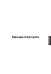
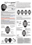
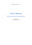
VTP Rem W
Ventilconvettore a parete
Fan coil for wall application
23
°F
%
°C
IR
Z
FAN
DRY
ON
OFF
G
DAY
TIME
ESH
NET
I
EN
HEAT
SLEEP SWING
AUTO
SUN MON TUE WED THU FRI SAT
WIN
Z
Z
COOL
HEATER
23 : 23
TIMER
ERR
UNIT
FAN
MODE
CANCEL
SLEEP
23
G
PARAMETERS
SWIN
FRESH
MANUALE UTENTE
USER MANUAL
Gentile cliente,
La ringraziamo per aver preferito nell'acquisto un climatizzatore FERROLI. Esso è frutto di pluriennali esperienze e di
particolari studi di progettazione, ed è stato costruito con materiali di primissima scelta e con tecnologie
avanzatissime.La marcatura CE, inoltre, garantisce che gli apparecchi rispondano ai requisiti della Direttiva Macchine Europea in materia di sicurezza.Il livello qualitativo è sotto costante sorveglianza, ed i prodotti FERROLI sono
pertanto sinonimo di Sicurezza, Qualità e Affidabilità.Il nostro Servizio di Assistenza più vicino, se non conosciuto,
può essere richiesto al Concessionario presso cui l'apparecchio è stato acquistato, o può essere reperito sulle Pagine Gialle sotto la voce "Condizionamento" o "Caldaie a gas" (valido solo per il mercato italiano). I dati possono subire
modifiche ritenute necessarie per il miglioramento del prodotto.
Nuovamente grazie.
FERROLI S.p.A
Dear Customer,
Thank you for having purchased a FERROLI Idustrial coolers. It is the result of many years experience, particular
research and has been made with top quality materials and higlly advanced technologies. The CE mark guaranteed
thats the appliances meets European Machine Directive requirements regarding safety. The qualitative level is kept
under constant surveillance. FERROLI products therefore offer SAFETY, QUALITY and RELIABILITY.Due to the continuous improvements in technologies and materials, the product specification as well as performances are subject
to variations without prior notice.
Thank you once again for your preference.
FERROLI S.p.A
La ditta costruttrice declina ogni responsabilità per le inesattezze contenute nel presente, se dovute ad errori di
stampa o di trascrizioni.
The manufacturer declines all responsibility for any inaccuracies in this manual due to printing or typing errors.
SOMMARIO
CARATTERISTICHE GENERALI . . . . . . . . . . . . . . . . . . . . . . . . . . . . . . . . . . . . . . . . . . . . . . . . . . . . . . . . . . . 4
RICEVIMENTO . . . . . . . . . . . . . . . . . . . . . . . . . . . . . . . . . . . . . . . . . . . . . . . . . . . . . . . . . . . . . . . . . . . . . 4
PREMESSA . . . . . . . . . . . . . . . . . . . . . . . . . . . . . . . . . . . . . . . . . . . . . . . . . . . . . . . . . . . . . . . . . . . . . . . . 4
Direttive europee . . . . . . . . . . . . . . . . . . . . . . . . . . . . . . . . . . . . . . . . . . . . . . . . . . . . . . . . . . . . . . . . . . . . 4
INSTALLAZIONE DEL COMANDO . . . . . . . . . . . . . . . . . . . . . . . . . . . . . . . . . . . . . . . . . . . . . . . . . . . . . . . . . 5
DATI TECNICI UNITA’ . . . . . . . . . . . . . . . . . . . . . . . . . . . . . . . . . . . . . . . . . . . . . . . . . . . . . . . . . . . . . . . . 5
MESSA IN FUNZIONE . . . . . . . . . . . . . . . . . . . . . . . . . . . . . . . . . . . . . . . . . . . . . . . . . . . . . . . . . . . . . . . . . . . 6
TASTI FUNZIONI E DISPLAY . . . . . . . . . . . . . . . . . . . . . . . . . . . . . . . . . . . . . . . . . . . . . . . . . . . . . . . . . . 6
INDICATORI LED UNITA’ . . . . . . . . . . . . . . . . . . . . . . . . . . . . . . . . . . . . . . . . . . . . . . . . . . . . . . . . . . . . . 7
ACCENSIONE DELL'UNITA' . . . . . . . . . . . . . . . . . . . . . . . . . . . . . . . . . . . . . . . . . . . . . . . . . . . . . . . . . . . 7
MODALITA' DI FUNZIONAMENTO . . . . . . . . . . . . . . . . . . . . . . . . . . . . . . . . . . . . . . . . . . . . . . . . . . . . . . 7
REGOLAZIONE DELLA TEMPERATURA . . . . . . . . . . . . . . . . . . . . . . . . . . . . . . . . . . . . . . . . . . . . . . . . . 8
REGOLAZIONE DEL VENTILATORE . . . . . . . . . . . . . . . . . . . . . . . . . . . . . . . . . . . . . . . . . . . . . . . . . . . . 8
FUNZIONAMENTO SLEEP . . . . . . . . . . . . . . . . . . . . . . . . . . . . . . . . . . . . . . . . . . . . . . . . . . . . . . . . . . . . 8
IMPOSTAZIONE DELL'ORA CORRENTE . . . . . . . . . . . . . . . . . . . . . . . . . . . . . . . . . . . . . . . . . . . . . . . . . 8
IMPOSTAZIONE DEL GIORNO CORRENTE . . . . . . . . . . . . . . . . . . . . . . . . . . . . . . . . . . . . . . . . . . . . . . 8
PROGRAMMAZIONE DEL TIMER . . . . . . . . . . . . . . . . . . . . . . . . . . . . . . . . . . . . . . . . . . . . . . . . . . . . . . 9
IMPOSTAZIONE MASTER SLAVE . . . . . . . . . . . . . . . . . . . . . . . . . . . . . . . . . . . . . . . . . . . . . . . . . . . . . . 9
IMPOSTAZIONE SINGOLA . . . . . . . . . . . . . . . . . . . . . . . . . . . . . . . . . . . . . . . . . . . . . . . . . . . . . . . . . . . .10
IMPOSTAZIONE GLOBALE . . . . . . . . . . . . . . . . . . . . . . . . . . . . . . . . . . . . . . . . . . . . . . . . . . . . . . . . . . . 10
SINCRONIZZAZIONE DEL TIMER IN MASTER-SLAVE . . . . . . . . . . . . . . . . . . . . . . . . . . . . . . . . . . . . . 10
PROGRAMMAZIONE DEL TIMER IN MASTER-SLAVE . . . . . . . . . . . . . . . . . . . . . . . . . . . . . . . . . . . . . 11
VISUALIZZAZIONE DEI PARAMETRI DELLE UNITA’ . . . . . . . . . . . . . . . . . . . . . . . . . . . . . . . . . . . . . . . . 11
BLOCCO FUNZIONI TASTIERA . . . . . . . . . . . . . . . . . . . . . . . . . . . . . . . . . . . . . . . . . . . . . . . . . . . . . . . . 12
TASTO DI EMERGENZA . . . . . . . . . . . . . . . . . . . . . . . . . . . . . . . . . . . . . . . . . . . . . . . . . . . . . . . . . . . . . . 12
FUNZIONE AUTO-RESTART . . . . . . . . . . . . . . . . . . . . . . . . . . . . . . . . . . . . . . . . . . . . . . . . . . . . . . . . . . .12
SPEGNIMENTO E MESSA A RIPOSO . . . . . . . . . . . . . . . . . . . . . . . . . . . . . . . . . . . . . . . . . . . . . . . . . . . 12
VISUALIZZAZIONE ERRORI CONTROLLO REMOTO . . . . . . . . . . . . . . . . . . . . . . . . . . . . . . . . . . . . . . .12
VISUALIZZAZIONE ERRORI UNITA' . . . . . . . . . . . . . . . . . . . . . . . . . . . . . . . . . . . . . . . . . . . . . . . . . . . . 13
MANUTENZIONE . . . . . . . . . . . . . . . . . . . . . . . . . . . . . . . . . . . . . . . . . . . . . . . . . . . . . . . . . . . . . . . . . . . . . . . 14
PULIZIA FILTRI . . . . . . . . . . . . . . . . . . . . . . . . . . . . . . . . . . . . . . . . . . . . . . . . . . . . . . . . . . . . . . . . . . . . . 14
PULIZIA DELL'UNITÀ . . . . . . . . . . . . . . . . . . . . . . . . . . . . . . . . . . . . . . . . . . . . . . . . . . . . . . . . . . . . . . . 14
3
CARATTERISTICHE GENERALI
RICEVIMENTO
Al momento del ricevimento dell'unità è indispensabile controllare di aver ricevuto tutto il materiale indicato sul
documento d'accompagnamento, ed inoltre che la stessa non abbia subito danni durante il trasporto. In caso
affermativo, far costatare allo spedizioniere l'entità del danno subito, avvertendo nel frattempo il nostro ufficio
gestione clienti. Soltanto agendo in questo modo e tempestivamente sarà possibile avere il materiale mancante
o il risarcimento dei danni.
PREMESSA
Il condizionatore è una macchina progettata e costruita esclusivamente per la climatizzazione e deve essere usata
solo per tale scopo. La macchina può funzionare bene e lavorare con profitto soltanto se usata correttamente e
mantenuta in piena efficienza. Preghiamo perciò di leggere attentamente questo libretto d'istruzioni e di rileggerlo
ogni qualvolta, nell'usare l'unità, sorgeranno delle difficoltà o dei dubbi. In caso di necessità ricordiamo comunque
che il nostro servizio d'assistenza, organizzato in collaborazione con i nostri concessionari, è sempre a disposizione
per eventuali consigli e interventi diretti.
DIRETTIVE EUROPEE
L'azienda dichiara che la macchina in oggetto è conforme a quanto prescritto dalle seguenti direttive e successive
modificazioni :
• Direttiva bassa tensione 2006/95/CE;
• Direttiva compatibilità elettromagnetica 2004/104/CE;
4
INSTALLAZIONE DEL COMANDO
DATI TECNICI UNITA’
Come prima cosa è necessario scegliere in quale punto installare il controllore remoto; in base alla dimensione ed
alla lunghezza dei collegamenti, predisporre una canalina adeguatamente dimensionata per contenere i cavi di collegamento oppure una apposita scatola di derivazione. Il disegno sotto indica le dimensioni del comando.
120
44
12
88
12
44
Fig.1
20
60
Per il fissaggio del controllo remoto, rimuovere la parte frontale dello stesso, rimuovere con delicatezza la scheda
elettronica al suo interno (fissata con viti al resto della struttura) e procedere al fissaggio del controllo tramite due viti,
come indicato dalle figure sottostanti.
Durante l’installazione del controllo remoto, si raccomanda di fare particolare attenzione al senso in cui viene fissato,
assicurarsi che la piastra sia correttamente orientata, prima di fissare le viti di ancoraggio.
N° Nome
1 Superficie del muro o scatola ad incasso
2 Retro del controller remoto
3 Vite M4 x 10
4 Controller remoto
Fig.2
Attenzione: il controllore è dotato di cavo a corredo di lunghezza 7m.
Si ricorda di non installare il controllore remoto in punti dove possa venire in contatto diretto con flussi
d’acqua o grandi quantità di vapore.
5
MESSA IN FUNZIONE
TASTI FUNZIONI E DISPLAY
Il comando (Fig. 1) è composto da una serie di tasti e da un display che visualizza tutte le funzioni attive ed i vari
parametri necessari all’utente ed all’installatore per un corretto utilizzo dell’unità stessa.
I tasti sono i seguenti:
23
°F
%
°C
IR
A sportello chiuso (Fig.1)
Z
FAN
DRY
2 e 3: Tasti per l’impostazione "TEMPERATURA
consentono di regolare la temperatura
ambiente della stanza: (+) ne imposta
l'aumento, (- ) ne imposta la diminuzione.
HEAT
SLEEP SWING
AUTO
SUN MON TUE WED THU FRI SAT
1.ON/OFF: Permette l’accensione e lo spegnimento
dell’unità.
Fig.1
Z
Z
COOL
ON
OFF
1
HEATER
23 : 23
23
ERR
UNIT
2
3
A sportello aperto (Fig.2)
3
°F
%
°C
Z
°F
%
°C
IR
Z
FAN
23
Z
1.MODE:
Permette di selezionare il modo di
HEAT
SLEEP SWING
AUTO
funzionamento:
UE WED THU FRI SAT HEATER
Raffreddamento,
Deumidificazione,
Sola
ON
ERR
:
OFF 23 23 UNIT
23 Riscaldamento e Automatico.
Ventilazione,
2.FAN: Pulsante di selezione della velocità del
ventilatore o di selezione automatica della velocità.
Gattivo
3. SWING: Non
SWIN
TIMER
FAN
4. FRESH:
PARAMETERNon attivo
ER
MODE
FRESH Per navigare tra i parametri delle
5. PARAMETER:
SLEEP
CANCEL
diverse unità
6. SLEEP: Usato per impostare /cancellare la
modalità Sleep, indipendentemente dal modo in
cui sta operando l’unità.
7. TIMER :Per impostare la funzione Timer (ON)
accensione, (CANCEL) per annullare la funzione (
OFF) per lo spegnimento.
8. DAY :Per impostare la programmazione
giornaliera\settimanale del Timer
9. NET :Per il controllo della rete delle unità
10. TIME :Per impostare la l’orario
COOL
DRY
Z
FAN
DRY
HEAT
SLEEP SWING
AUTO
SUN MON TUE WED THU FRI SAT
ON
OFF
HEATER
23 : 23
ERR
UNIT
7
9
DAY
TIMER
NET
TIMER
FAN
MODE
6
3
2
3
CANCEL
G
PARAMETER
SLEEP
SWIN
5
FRESH
4
6
1
23
2
23
7
8
Dal display del telecomando sono visualizzate le seguenti impostazioni:
-a) Modo di funzionamento, rispettivamente:
Freddo, Ventilazione, Deumidificazione e
Riscaldamento.
c
a
L’ accensione contemporanea del simbolo freddo caldo
indica che l’unità è impostata in Automatico
-b) Velocità del ventilatore selezionata, rispettivamente:
°F
IR
Media, Minima, Massima ed Automatica.
% COOL FAN DRY HEAT
-c)Valore del Set point impostato (dopo pochi secondi
°C
viene visualizzato la temp. ambiente)
SUN MON TUE WED THU FRI SAT HEATER
-d) Ora corrente (o segnale di allarme)
ON
-e) Impostazione Timer
OFF
-f) indicatori giorno selezionato
-g) Funzione SLEEP attiva
-h) Indicatore trasmissione segnale alla rete dei
ventilconvettori.
f
l
e
d
-i) indicazione numero di Unità selezionata della rete
-l) indicazione tastiera bloccata
1
Fig.2
Z
Z
COOL
23 : 23
Fig.3
g
Z
Z
Z
SLEEP SWING
AUTO
23
ERR
UNIT
h
i
b
MESSA IN FUNZIONE
Fig.4
INDICATORI LED UNITA’
Di seguito viene descritto il significato dei LED situati nel pannello
frontale dell’unità interna:
1. INDICATORE POWER (verde)
Si illumina di quando l’unità è alimentata.
2. INDICATORE PROTEZIONI ATTIVE (rosso)
Si illumina quando sono attive alcune protezioni o allarmi.
3. INDICATORE TEMPERATURA e RICEVITORE
Indica la temperatura impostata ambiente il ricevitore riceve i
segnali dal telecomando
4. INDICATORE MODALITA’ATTIVA (verde) SUN MON TUE
Si illumina di quando l’unità è in funzione.
5. INDICATORE TIMER (giallo)
Si illumina quando è attivo il TIMER.
23
23
IR
IR
°F
% COOL FAN DRY HEAT
°F
°C
COOL FAN DRY HEAT
%
WED THU FRI SAT HEATER
°C ON
AUT
AU
ERR
UNIT
ERR
UNI
AUTO
1
2
23 :2323
23 : 23
3
4
°C
5
SUN MON TUE WED THU
HEATER
OFFFRI SAT 18:88
ON
Fig.5
OFF
AM
PM
ACCENSIONE DELL'UNITA'
Per accendere il condizionatore, premere il pulsante di ON/OFF (Fig. 5). La lucespia verde del condizionatore si accenderà, indicando che è stato avviato. Tenete
presente che il visualizzatore a cristalli liquidi indicherà sempre l'ultimo modo
di funzionamento e le funzioni precedentemente usate. Seguite le istruzioni se
desiderate modificare il modo di funzionamento del sistema.
FAN
ON
OFF
SLEEP LOUVER
MODE
TIMER FUNCTION
SWING
ON CANCEL OFF
MODALITA' DI FUNZIONAMENTO
DAY
DAY
TIME
TIMER
FAN
Fig.6
Premendo il tasto “MODE” (Fig.6) si selezionano i vari modi di funzionamento
preferito, scegliendo tra i seguenti:
AUTO - FREDDO- DEUMIDIFICAZIONE - FAN - CALDO.
1.AUTO Funzionamento Automatico: questa funzione è selezionata premendo il
tasto MODE fino a visualizzare a display contemporaneamente il simbolo freddo
e caldo. L unità imposta automaticamente il modo di funzionamento (FREDDOCALDO) in base alla temperatura dell’acqua in arrivo all’unità.
2.FREDDO Funzionamento in raffreddamento: questa funzione è selezionata
premendo il tasto MODE fino a visualizzare a display il relativo simbolo.
L’unità inizia a funzionare in raffreddamento e si porta velocemente vicino alla
temperatura ambiente richiesta.
NET
NET
TIMER MODE FAN
TIME CANCEL
MODE SLEEP
SLEEP
CANCEL
3.DEUMIDIFICAZIONE Funzionamento deumidificazione: questa funzione è selezionata premendo il tasto MODE
fino a visualizzare a display il relativo simbolo. L’unità inizia a funzionare in raffreddamento con tempi di accensione
spegnimento che dipendono dal valore della temperatura ambientale. La velocità del ventilatore non è modificabile.
4.FAN Funzionamento ventilazione: questa funzione è selezionata premendo il tasto MODE fino a AUTO
visualizzare a
display il relativo simbolo.
5.CALDO Funzionamento in riscaldamento: questa funzione è selezionata premendo il tasto MODE fino a
visualizzare a display il relativo simbolo. L’unità inizia a funzionare in riscaldamento e si porta velocemente vicino
alla temperatura ambiente richiesta.
°C
23
18:88
AM
PM
ON
OFF
7
P
23
23
°F
IR
HEAT
SLEEP SWING
% IRCOOL FAN DRY
°F
MESSA IN FUNZIONE
AUTO
%
°C
°C
SUN MON TUE WED THU FRI SAT HEATER
°F
IR
REGOLAZIONE
DELLA
TEMPERATURA
23 : 23
23
23
FAN DRY HEAT 23 : 23
SLEEP Fig.1
SWING
% COOL ON
: AUTOERR
UNIT
OFF
°C i tasti (+) e (-)”
Per modificare la temperatura di set point utilizzare
Z
Z
Z
OOL
FAN
DRY
HEAT
SLEEP SWING
AUTO
HU FRI SAT
ON
OFF
HEATER
ERR
UNIT
Z
23
23 23
COOL
FAN
SW
SLEEP
FRESH
MODE
ANCEL
3 23
°F
%
°C
DAY
°F
%
°C
TIME
EHEATER
SAT
WED THU
HEATER
FRI
MON SAT
TUE WED
HEATER
THU FRI SAT
SUN
TIME
NET
Per modificare la velocità del ventilatore premere il tasto FAN (Fig.2) Il
Z
Z
Z
Z
Z
Z
Z
Z
Z
display visualizzerà
il simbolo associato
alla velocità
selezionata, min
Z
Z
Z
Med, Max oZ Auto. Z
Z
RY
AN HEAT
DRY
COOL HEAT
FAN SLEEP
DRY SWING
COOL
SLEEP
HEAT FAN
SWING DRY
SLEEPHEAT
SWING
SLEEP SWING
EEP SWING
AUTO AUTO
AUTO
AUTO
HEATER
DAYNET
:
IR TIMER
HEAT
AUTO
HEATER
ERR
UNIT
TIMER
Z
SLEEP SWING
Z
Z
Z
HEATER
23 : 23
ON DAY
OFF
REGOLAZIONE
DEL VENTILATORE
PARAMETERS
Z
Z
DRY
ON
OFF
SUN MON TUE WED THU FRI SAT
IMER
FAN
SUN MON TUE WED THU FRI SAT
(Fig.1.) Il tasto (+) ne imposta l'aumento, (-) ne imposta la diminuzione.
ING
Z
Z
FAN
MODE
ERR
UNIT
23
23
PARAMETERS
Fig.2
SLEEP
CANCEL
23
N
SWI
FRES
SW
FAN
°F
%
°C
MODE
COOL
FAN DRY
PARAMETERS
H
FR
CANCEL SUN MON TUESLEEP
ING
WED THU FRI SAT SW
HEAT
:
:
TIMER
FAN
Fig.3
ON
TIME
PARAMETERS
La pressione del tasto “SLEEP” (Fig.3), predispone la macchina nella
MODE
OFF
modalità di funzionamento notturno evidenziato dal relativo simbolo sul
display. La temperatura aumenta (funzionamento in freddo “COOL”),
°F
NET
FRESH
IRoppure 1 °C ad
o diminuisce (funzionamento in caldo “HEAT”), di 0,5
CANCEL
FAN DRY HEAT
SLEEP SWING
% COOL SLEEP
: 2323
23
23 2323
23 23
23
ON ERR
ON
ERR
ERR
FUNZIONAMENTO SLEEP
UNIT
OFF UNIT
OFF UNIT
23
ERR
UNIT
23
23 : 2
23
intervalli prestabiliti.
Z
Z
Z
°C
volta
SLEEP
G
DAY Premendo una seconda
NG la Nmodalità
INGsi disattiva SWSUN
INGMON TUE WED THU FRI SAT HEATER
SWI SWI
TIMER
TIMER
FAN FAN
FAN
FANSW
ON
ERR
Z
E
TIME
PARAMETERS
PARAMETERS
PARAMETERS
PARAMETERS
:
Z
UNIT
CORRENTE
OFF
DE°FMODEIMPOSTAZIONE
MODE DELL'ORA
MODE
Fig.4
°F
Z
IR
COOL FAN DRY HEAT
SLEEP
SWING
COOL FAN DRY HEAT
IR
NETCANCEL
FRESH
FRESH
FRESH
FRESH
%
%
1
SLEEP
SLEEP
SLEEP
SLEEP
CANCEL
Y°C HEAT
SLEEP
AUTO SWING
Per modificare
l’impostazione dell’ora corrente tenere premuto uno
G
DAdeiY SUN MON TUE °CWED THU FRI SAT HEATER
N
I
AUTO
WED THU FRI
SAT
HEATER
2
tasi TIME
W(+) o (-) (Fig.4)
3
Z
23 23
23
Z
Z
S
:
HEATER 23 23
AMETERS
AUTO
23
ON Il comando visualizza
ERRl ‘ora impostata. La velocità di scorrimento dell’ora
in cui è mantenuto premuto il tasto di regolazione.
OFFdipende dal tempo UNIT
ERR
: 23 FRESH
UNIT
Z
Z
23
NET
Z
NG
HEAT
SLEEPFAN
SWING
IMPOSTAZIONE
DEL GIORNO CORRENTE
SWI
TIMER
AUTO
PARAMETERS
IR
DAY
23
23
Z
SLEEP S
%
°C
AUTO
Z
Z
CO
TIMER ERR
:MON
20:30
23
23TUEUNITWED2T
SUN
MODE
CANCEL
ON
OFF
TIME
3
23 °F
°F
% COOL FANFig.5
TIMER
FANDRY HEAT
TIME
PARAMETE
°C MODE
MODE
Per
modificare
l’impostazione
del
giorno
corrente
tenere
premuto
il
tasto
FRESH
NET
ATER
SUN MON TUE
WED THU FRI SLEEP
SAT HEATER
SLEEP
CANCEL
CANCEL
23
(DAY) (Fig.5).
Il ERR
comando visualizza il giorno impostato.
UNIT
FAN
E
SLEEP
8
FAN
23
ING
SW
PARAMETERS
FRESH
G
WIN
S
DAY
ON
OFF
23 : 23
TIME
DAY
NET
TIMER
T
CA
FA
23
°C
SUN MON TUE WED THU FRI SAT
3
ON
OFF
MESSA IN FUNZIONE
PROGRAMMAZIONE DEL TIMER
Z
23
IR
Il tasto TIMER e CANCEL (Fig.6) consentono di impostare l’orario di
SLEEP
SWINGdi spegnimento o di annullare ogni impostazione oraria. Per
accensione,
la programmazione procedere come segue.
AUTO
1- Premendo una volta il tasto TIMER viene visualizzata l’icona relativa
alla fase ON e l’orario impostato per l’accensione. Mediante i tasti (+) e
(-) della funzione TIME ( Fig. 4) è possibile modificare tale impostazione.
La velocità di scorrimento dell’ora dipende dal tempo in cui è mantenuto
premuto il tasto di regolazione. Selezionare quindi mediante il tasto DAY
ERR
quale giorno è richiesto per l’attivazione del timer
UNIT
2- Premendo una seconda volta il tasto TIMER viene visualizzata l’icona
relativa alla fase OFF e l’orario impostato per lo spegnimento. Mediante
i tasti (+) e (-) della funzione TIME ( Fig. 4) è possibile modificare tale
impostazione. La velocità di scorrimento dell’ora dipende dal tempo in
cui è mantenuto premuto il tasto di regolazione.
3-Per cancellare ogni impostazione del Timer premere il tasto CANCEL
per tre secondi.
NG
DAY
SWI
23
FRESH
P
23 : 23
°F
%
°C
Z
Z
HEATER
Fig.6
COOL
ERR
UNIT
FAN
SUN MON TUE WED THU FRI SAT
TIMER
TIME
NET
MODE
CANCEL
NG
DAY
SWI
IMPOSTAZIONE MASTER SLAVE
FAN
23P
ON
OFF
SLEEP
TIMER
Le informazioni di controllo che provengono dal controllore al Master vengono condivisione
con altre unità facenti
TIME
PARAMETERS
parte del gruppo. Tra queste informazioni condivise ci sono:
- Accensione\Spegnimento
- Modo di funzionamento
- Velocità del ventilatore
- Temperatura di Set Point
- Impostazione aletta
- Attivazione funzione Sleep
- Accensione\Spegnimento Temporizzate
Sono disponibili due modalità di gestione:
- mediante indirizzo singolo ( ad ogni unità possono essere associate impostazioni diverse). E’ necessario in questo
caso un indirizzamento delle diverse unità da farsi in fase di installazione.
- mediante indirizzamento globale. In questo caso tutte le unità assumono le medesime impostazioni.
FRESH
IR
23
°F
%
°C
Z
FAN
DRY
HEAT
23
°F
%
°C
Z
Z
COOL
NET
SLEEP SWING
IR
AUTO
SUN MON TUE WED THU FRI SAT
ON
OFF
HEATER
23 : 23
ERR
UNIT
Z
FAN
DRY
DAY
TIME
°F
%
°C
IR
SLEEP SWING
AUTO
ON
OFF
NET
HEAT
23
Z
Z
COOL
SUN MON TUE WED THU FRI SAT
23
HEATER
23 : 23
TIMER
ERR
UNIT
FAN
MODE
CANCEL
SLEEP
PARAMETERS
Z
FAN
DRY
SWIN
G
DAY
NET
TIME
HEAT
SLEEP SWING
AUTO
ON
OFF
FRESH
Z
Z
COOL
SUN MON TUE WED THU FRI SAT
23
CANCEL
HEATER
23 : 23
TIMER
ERR
UNIT
FAN
MODE
CANCEL
SLEEP
23
G
PARAMETERS
SWIN
FRESH
9
MO
: 23
23
UNIT
23
IR
SUN MON TUE WED THU FRI SAT
23
23 : 23
Z
Z
Z
SWING
Mediante i tasti
(+) eWED
(-) ( THU
Fig 1)
selezionare il numero
SUN TIME
MON TUE
FRIè possibile
SAT HEATER
dell’un unità su cui si vuole operare. Unità spente non vengono visualizzate.
Impostare i parametri richiesti e quindi
ON passare all’unità successiva
ERR oppure
uscire dalla modalità di impostazione singola mediante il tasto NET
UNIT
FRESH
SLEEP
Z
OFF
Z
Z
Z
23 : 23
Z
Z
HEAT
SLEEP SWING
DAY
SLEEP SWING
AUTO
AUTO IMPOSTAZIONE GLOBALE
ATER
D
AY
Z
SLEEP SWING
AUTO
Fig. 1
23
IR
IR
FAN
ERR
UNIT
23TIME
DAY
T
NET
CA
2323
°F
°F
COO
Fig. 2 %G
FAN
N
I
% COOL
SW °C
°C
PARAMETERS
SUN MON TUE WED THU
G
WIN MON TUE WED THU FRI SAT
SSUN
FANMODE
O
FRESH
ON
PARAMETERS
SLEEP
CANCEL
MODE
O
OFF
FRESH
SLEEP
CANCEL
TIMER
Tenere premuto contemporaneamente per tre secondi i tasti SWING e
FRESH
ERR( Fig.2). Il display visualizza il simbolo riportato in (Fig 3). Eseguire
le impostazioni.
PerUNIT
uscire premere nuovamente per tre secondi i tasti SWING e FRESH.
23 23NET23
ERR
UNIT
TIME
TIMER
Z
Z
HEATER
°F
G ON
INFAN
W
COOL
DRY
SLEEP
S
%
FAN
OFF HEAT
Premere il tasto NET, il display visualizzerà quale unità è sottoAUTO
controllo.
( Fig.1)
PARAMETERS°C
IMPOSTAZIONE SINGOLA
IR
E
P
°F
COOL INFAN
DRY HEAT
FUNZIONE
%MESSA
°C
TIME
NET
23
Fig. 3
SINCRONIZZAZIONE DEL TIMER IN MASTER-SLAVE
ING
G
W
S
N
I
FAN
SW
PARAMETERS
PARAMETERS
FRESH
SLEEP
FRESH
E’ possibile sincronizzare l’ora corrente su tutte le unità facenti parte del
gruppo. Premere contemporaneamente per tre secondi i tasti (+) e (-).
L’unità MASTER segnalerà l’avvenuta sincronizzazione mediante un
BEEP
10
DAY
NET
DAY
TIME
NET
TIMER
TIME
TIM
MO
CAN
CANCEL
3 : 23
DE
G
WINIR
RESH
23
ERR
UNIT
23
IR
°FMESSA IN FUNZIONE
% COOL FAN DRY HEAT
°C
PROGRAMMAZIONE
DELMON
TIMER
IN MASTER-SLAVE
TUE
WED THU FRI
SUN
SAT
Z
Z
Z
SLEEP SWING
AUTO
Fig. 1
HEATER
23 : 23
ON
Gunico pannello
Qualora si volesse associare mediante
un
di controllo
WalleINdiverse unità
diverse impostazione del TIMER
SLAVE facenti
S
FAN
OFF
parte del gruppo si deve innanzi tutto selezionare quale unità
impostare.
PARAMETERS
Premere il tasto NET, il display visualizzerà quale unità è sotto
23TIME
DAY
ERR
UNIT
controllo. ( Fig.1)
Mediante i tasti TIME (+) e (-) è possibile selezionare il numero dell’un
unità su cui si vuole operare. Unità spente non vengono visualizzate.
1-Premendo una seconda volta il tasto TIMER viene visualizzata
l’icona relativa alla fase ON. Selezionare quindi mediante il tasto
COOL FAN DRY HEAT
DAY quale giorno è richiesto per l’attivazione del timer. Il MASTER
recupera i dati attualmente impostati sull’unità selezionata. Tale fase
è evidenziata dalla scritta rEAd. A questo punto mediante i tasti (+)
e (-) della funzione TIME è possibile modificare tale impostazione.
TUE WED THU FRI SAT HEATER
SUN MON l’icona
2- Premendo una terza volta il tasto TIMER viene visualizzata
relativa alla fase OFF e l’orario impostato per lo spegnimento.
ON
Ripetere la medesima operazione sopra descritta per impostarne
l’ora.
OFF
3-Per cancellare ogni impostazione del Timer premere il tasto
CANCEL per tre secondi.
FRESH
IR
SLEEP
23
DAY
TIMER
TIME
NET
NET
°F
%
°C
FAN
Z
Z
SLEEP
NG
SWI
ERR
UNIT
FRESH
SLEEP
CANCEL
Z
AUTO
PARAMETERS
: 23
READ
23
MODE
C
2
VISUALIZZAZIONE DEI PARAMETRI DELLE UNITA’
DAY
Qualora si volessero vedere le condizioni di lavoro delle diverse
unità tenere premuto contemporaneamente per tre secondi i tasti
°F
IR
CANCEL %e COOL
FANFAN( Fig.3).
visualizza l’unità attiva. Per
DRY HEAT Il display
SLEEP SWING
scoorere °C
tra le unità utilizzare la
modalità già descritta.
AUTO
Una
volta
selezionata
l’unità il display visualizzerà il parametro
TUE WED
THU FRI SAT HEATER
SUN MON
selezionato edONil suo valore ( Fig
ERR 3)
:
Per uscire dalla
il tasto CANCEL.
UNIT
OFFnavigazione premere
23
Z
Z
23 23
Parametri visualizzabili
DAY
TIMER
FAN
Z
23 NET
TIME
NG
SWI
23
°F
TIMER
%
Parametro
Dato associato
PARAMETERS
TIME
MODE
Temperatura
aria FRESH
ambiente letta
NET C0
SLEEP
CANCEL
C1
Temperatura scambiatore
C2
Impostazione DIP Switch
C3
Temperatura scambiatore supplementare
°C
Z
FAN
DRY
CANCEL
TIME
NET
HEAT
Z
ON
OFF
SLEEP SWING
AUTO
MODE
SUN MON TUE WED THU FRI SAT
DAY
FAN
Z
COOL
HEATER
23 : 23
TIMER
ERR
UNIT
SLEEP
FAN
MODE
CANCEL
23
PARAMET
SLEEP
NG
PARAMETERS
SWI
FRESH
11
23
°C
Z
MESSA IN FUNZIONE
IR
Z
Z
COOL
FAN
DRY
HEAT
SLEEP SWING
23
AUTO
BLOCCO FUNZIONI TASTIERA
ED THU FRI SAT
ON
OFF
HEATER
23 : 23
FAN
MODE
23
PARAMETERS
TASTO DI
EMERGENZA
SLEEP
NG
DAY
FRESH
NET
SWI
RS
FAN
ON
OFF
DRY
23
FUNZIONE AUTO-RESTART
N
PARAMETERS
MODE
DAY
SLEEP
COOL
FAN
1
DRY
23
ERR
UNIT
FAN
SUN MON TUE WED THU FRI SAT
L’unità è programmata per accendersi automaticamente in caso di
interruzione di corrente elettrica.
Z
SLEEP SWING
Fig. 1
AUTO
23 : 23
CANCEL
°F
%
°C
HEAT
HEATER
TIMER
TIME
IR
SWING
23
H
COOL
SUN MON TUE WED THU FRI SAT
Permette il funzionamento di emergenza in caso di rottura del comando.
Mediante pressione ripetuta del pulsante è possibile impostare le
seguenti modalità di funzionamento: Freddo, Caldo, OFF. In entrambi i
casi il set point viene automaticamente selezionato dall’unità cosi come
la velocità del ventilatore verrà scelta dall’unità.
Il bottone Emergenza ON/OFF è su angolo in alto a destra sotto al
pannello (1 Fig.2).
G
Z
Z
E’ possibile
le funzioni della tastiera tenendo premuto
contemporaneamente i tasti (+) e (-) per tre secondi.
Sul display appare il simbolo relativo (fig.1).
Per riattivare le funzioni della tastiera eseguire la medesima procedura.
Nel caso di blocco tastiera rimane attiva solo la funzione di Accensione\
Spegnimento
TIMER
CANCEL
ERR
UNIT
bloccare
SUN MON TUE W
°F
%
°C
Fig. 2
SWI
FRES
Z
Z
Z
HEAT
SLEEP
AUTO
HEATER
TIME
: 23
23
NET
ON
OFF
ERR
UNIT
Fig. 3
2
SPEGNIMENTO E MESSA A RIPOSO
Per spegnere l’unità basta premere il tasto di "ON/OFF" (Fig. 3) sul
comando.
DAY
ING
SWVISUALIZZAZIONE
ERRORI CONTROLLO REMOTO
23
TIMER
FAN
°F
TIME
PARAMETE
Nel caso insorgesse una condizione di errore durante il funzionamento dell’unità, o di una
delle unità della serie,
MODE
FANindicazione
DRY delHEAT
SWING
tale condizione sarà visualizzata
segnale di codice SLEEP
errore 1.Fig.
1 e dell’unità a quale tale
% COOLmediante
FRESH
errore è associato 2.Fig 4. Il pannello segnalerà loNET
stato di errore mediante cambio del colore della retroilluminazione.
SLEEP
CANCEL
AUTO
Per interpretare i codici
di errore, utilizzare la tabella sottostante:
°C
Z
SUN MON TUE WED THU FRI SAT
ON
OFF
HEATER
E2
23 : 23
1
12
DAY
Z
Z
ERR
UNIT
23
Fig. 4
2
G
WIN
MESSA IN FUNZIONE
Codice
Errore
E1
E2
E3
E4
Tipo di errore
Note
Azioni*
Allarme ( non previsto per queste unità)
Allarme ( non previsto per queste unità)
Allarme
Allarme
E7
Errore sulla resistenza elettrica
Errore sulla sonda batteria T2
Errore sulla sonda aria ambiente
Errore sulla sonda batteria T1
Protezione per temperatura
scambiatore troppo bassa
Protezione per temperatura
scambiatore troppo alta
Errore Flow switch
E8
Errore di comunicazione
Allarme
E5
E6
Protezione temporanea
Protezione temporanea
Allarme ( non previsto per queste unità)
\
\
Chiamare l’assistenza tecnica
Chiamare l’assistenza tecnica
Se l’allarme non scompare
chiamare l’assistenza tecnica
Se l’allarme non scompare
chiamare l’assistenza tecnica
\
Se l’allarme non scompare
chiamare l’assistenza tecnica
* alcuni allarmi potrebbero essere generati da una carente manutenzione ordinaria. Si raccomanda di eseguire tale
procedura prima di far intervenire l’Assistenza Tecnica.
Fig. 5
VISUALIZZAZIONE ERRORI UNITA'
Nel caso insorgesse una condizione di errore durante il
funzionamento dell’unità, tale condizione sarà visualizzata
mediante lampeggio del LED 4 posto sul pannello. In funzione del
numero di lampeggi è possibile identificare la causa l’errore. Per
interpretare i codici di errore, utilizzare la tabella sottostante:
N°
lampeggi
1
2
3
4
5
6
9
Tipo di errore
Note
Azioni*
Errore sulla resistenza elettrica
Errore sulla sonda batteria T2
Errore sulla sonda aria ambiente
Errore sulla sonda batteria T1
Protezione per temperatura
scambiatore troppo bassa
Protezione per temperatura
scambiatore troppo alta
Allarme ( non previsto per queste unità)
Allarme( non previsto per queste unità)
Allarme
Allarme
Errore sul motore del ventilatore
Protezione temporanea
\
\
Chiamare l’assistenza tecnica
Chiamare l’assistenza tecnica
Se l’allarme non scompare
chiamare l’assistenza tecnica
Se l’allarme non scompare
chiamare l’assistenza tecnica
Se l’allarme non scompare
chiamare l’assistenza tecnica
Protezione temporanea
Protezione temporanea
* alcuni allarmi potrebbero essere generati da una carente manutenzione ordinaria. Si raccomanda di eseguire tale
procedura prima di far intervenire l’Assistenza Tecnica.
Come interpretare il numero associato ai lampeggi.
3 sec
La (Fig. 2) indica la sequenza di 3 lampiggi distanziati da un
periodo di sosta di 3 sec.
13
MANUTENZIONE
PULIZIA FILTRI
Per un corretto funzionamento dell'apparecchio è necessario
controllare e pulire periodicamente il filtro dell'aria. Per fare ciò
procedere come indicato in seguito (Fig. 1):
1. Staccare la spina dalla presa di corrente.
2. Sollevare il pannello frontale.
3. Togliere la griglia di aspirazione tirandola verso l'esterno.
4. Rimuovere i filtri spingendo in alto le linguette centrali fino a che si
liberano dal fermo e sfilarli tirandoli verso il basso.
5. Lavarli con acqua o pulirli con l'aspirapolvere.
6. Rimontare il tutto nella posizione iniziale.
Fig. 1
N.B. Quest'operazione è da compiere almeno una volta al mese (la
frequenza degli interventi di pulizia varia secondo le caratteristiche e
della polvere presente nel locale da condizionare) o quando la spia
filtro si accende.
Fig. 2
PULIZIA DELL'UNITÀ
Per eseguire la pulizia dell'unità procedere come indicato in seguito
(Fig.2):
1. Pulire con un panno umido.
2. Non pulire con getti d'acqua diretti per evitare di danneggiare i
componenti elettrici.
3. Non pulire utilizzando alcool o altre sostanza corrosive
14
SUMMARY
MAIN CHARACTERISTICS . . . . . . . . . . . . . . . . . . . . . . . . . . . . . . . . . . . . . . . . . . . . . . . . . . . . . . . . . . . . . . . 4
RECEIPT . . . . . . . . . . . . . . . . . . . . . . . . . . . . . . . . . . . . . . . . . . . . . . . . . . . . . . . . . . . . . . . . . . . . . . . . . . 4
FOREWORD . . . . . . . . . . . . . . . . . . . . . . . . . . . . . . . . . . . . . . . . . . . . . . . . . . . . . . . . . . . . . . . . . . . . . . . 4
European Directives . . . . . . . . . . . . . . . . . . . . . . . . . . . . . . . . . . . . . . . . . . . . . . . . . . . . . . . . . . . . . . . . . . 4
CONTROL INSTALLATION . . . . . . . . . . . . . . . . . . . . . . . . . . . . . . . . . . . . . . . . . . . . . . . . . . . . . . . . . . . . . . . 5
UNIT TECHNICAL DATA . . . . . . . . . . . . . . . . . . . . . . . . . . . . . . . . . . . . . . . . . . . . . . . . . . . . . . . . . . . . . . 5
STARTUP . . . . . . . . . . . . . . . . . . . . . . . . . . . . . . . . . . . . . . . . . . . . . . . . . . . . . . . . . . . . . . . . . . . . . . . . . . . . . 6
FUNCTION BUTTONS AND DISPLAY . . . . . . . . . . . . . . . . . . . . . . . . . . . . . . . . . . . . . . . . . . . . . . . . . . . 6
UNIT LED INDICATORS . . . . . . . . . . . . . . . . . . . . . . . . . . . . . . . . . . . . . . . . . . . . . . . . . . . . . . . . . . . . . . 7
UNIT ACTIVATION . . . . . . . . . . . . . . . . . . . . . . . . . . . . . . . . . . . . . . . . . . . . . . . . . . . . . . . . . . . . . . . . . . . 7
OPERATION MODE . . . . . . . . . . . . . . . . . . . . . . . . . . . . . . . . . . . . . . . . . . . . . . . . . . . . . . . . . . . . . . . . . .7
TEMPERATURE ADJUSTMENT . . . . . . . . . . . . . . . . . . . . . . . . . . . . . . . . . . . . . . . . . . . . . . . . . . . . . . . . 8
FAN SPEED ADJUSTMENT . . . . . . . . . . . . . . . . . . . . . . . . . . . . . . . . . . . . . . . . . . . . . . . . . . . . . . . . . . . 8
SLEEP MODE . . . . . . . . . . . . . . . . . . . . . . . . . . . . . . . . . . . . . . . . . . . . . . . . . . . . . . . . . . . . . . . . . . . . . . 8
SETTING THE CURRENT TIME . . . . . . . . . . . . . . . . . . . . . . . . . . . . . . . . . . . . . . . . . . . . . . . . . . . . . . . . 8
SETTING THE CURRENT DAY . . . . . . . . . . . . . . . . . . . . . . . . . . . . . . . . . . . . . . . . . . . . . . . . . . . . . . . . . 8
TIMER PROGRAMMING . . . . . . . . . . . . . . . . . . . . . . . . . . . . . . . . . . . . . . . . . . . . . . . . . . . . . . . . . . . . . . 9
MASTER SLAVE SETTING . . . . . . . . . . . . . . . . . . . . . . . . . . . . . . . . . . . . . . . . . . . . . . . . . . . . . . . . . . . . 9
SINGLE SETTING . . . . . . . . . . . . . . . . . . . . . . . . . . . . . . . . . . . . . . . . . . . . . . . . . . . . . . . . . . . . . . . . . . 10
GLOBAL SETTING . . . . . . . . . . . . . . . . . . . . . . . . . . . . . . . . . . . . . . . . . . . . . . . . . . . . . . . . . . . . . . . . . . 10
SYNCHRONISING TIMER IN MASTER-SLAVE . . . . . . . . . . . . . . . . . . . . . . . . . . . . . . . . . . . . . . . . . . . . 10
PROGRAMMING TIMER IN MASTER-SLAVE . . . . . . . . . . . . . . . . . . . . . . . . . . . . . . . . . . . . . . . . . . . . . 11
UNIT PARAMETERS DISPLAY . . . . . . . . . . . . . . . . . . . . . . . . . . . . . . . . . . . . . . . . . . . . . . . . . . . . . . . . . 11
KEYPAD FUNCTIONS LOCK . . . . . . . . . . . . . . . . . . . . . . . . . . . . . . . . . . . . . . . . . . . . . . . . . . . . . . . . . . 12
EMERGENCY BUTTON . . . . . . . . . . . . . . . . . . . . . . . . . . . . . . . . . . . . . . . . . . . . . . . . . . . . . . . . . . . . . . 12
AUTO-RESTART FUNCTION . . . . . . . . . . . . . . . . . . . . . . . . . . . . . . . . . . . . . . . . . . . . . . . . . . . . . . . . . . 12
SHUTDOWN AND DEACTIVATION . . . . . . . . . . . . . . . . . . . . . . . . . . . . . . . . . . . . . . . . . . . . . . . . . . . . . . 12
REMOTE CONTROL ERRORS DISPLAY . . . . . . . . . . . . . . . . . . . . . . . . . . . . . . . . . . . . . . . . . . . . . . . . . 12
UNIT ERRORS DISPLAY . . . . . . . . . . . . . . . . . . . . . . . . . . . . . . . . . . . . . . . . . . . . . . . . . . . . . . . . . . . . . . 13
MAINTENANCE . . . . . . . . . . . . . . . . . . . . . . . . . . . . . . . . . . . . . . . . . . . . . . . . . . . . . . . . . . . . . . . . . . . . . . . . 14
FILTER CLEANING . . . . . . . . . . . . . . . . . . . . . . . . . . . . . . . . . . . . . . . . . . . . . . . . . . . . . . . . . . . . . . . . . . 14
UNIT CLEANING . . . . . . . . . . . . . . . . . . . . . . . . . . . . . . . . . . . . . . . . . . . . . . . . . . . . . . . . . . . . . . . . . . . .14
3
MAIN CHARACTERISTICS
RECEIPT
On receiving the unit it is essential to check the presence of all the material indicated on the accompanying
document, and also that it has not been damaged during transport. If so, immediately inform the forwarder regarding
the damage, at the same time also notifying our Customer Care department. Only in this way is it possible to promptly
obtain the missing material or compensation for damage.
FOREWORD
The air conditioner is designed and constructed exclusively for air conditioning and must only be used for that
purpose. The machine can operate properly and profitably only if used correctly and kept fully efficient. Therefore,
please read this instruction handbook carefully and reread it whenever any difficulties or doubts arise. In case of
need, our support service, organised in cooperation with our dealers, is always available for any advice and direct
assistance.
EUROPEAN DIRECTIVES
The Manufacturer declares that the machine in question complies with the requirements of the following directives
and subsequent amendments:
• Low Voltage Directive 2006/95/EC;
• Electromagnetic Compatibility Directive 2004/104/EC;
4
CONTROL INSTALLATION
UNIT TECHNICAL DATA
First it is necessary to choose where to install the remote controller; according to the size and the length of the
connections, arrange a raceway suitable for holding the connection cables or a special junction box. The figure below
shows the dimensions of the control.
120
44
12
88
12
44
Fig.1
20
60
To secure the remote control, remove the front part, carefully remove the electronic board inside (fixed with screws to
the rest of the structure) and fix the control by means of two screws, as shown in the figures below.
When installing the remote control, pay special attention to the direction in which it is fixed; make sure the plate is
oriented correctly before securing the anchor screws.
No. Name
1 Surface of wall or recess-mounting box
2 Back of remote controller
3 Screw M4 x 10
4 Remote controller
Fig.2
Attention: The controller is equipped with a 7m long cable.
Do not install the remote controller in a place where it could come into direct contact with flows of water or
large amounts of steam.
5
STARTUP
FUNCTION BUTTONS AND DISPLAY
The control (Fig. 1) has a number of buttons and a display that shows all the active functions and the various
parameters necessary to the user and installer for correct use of the unit.
The buttons are:
23
°F
%
°C
IR
With door closed (Fig.1)
Z
FAN
DRY
HEAT
SLEEP SWING
AUTO
SUN MON TUE WED THU FRI SAT
ON
OFF
1. ON/OFF: For switching the unit on and off.
Fig.1
Z
Z
COOL
1
HEATER
23 : 23
23
ERR
UNIT
2
2 and 3: TEMPERATURE setting buttons for adjusting
the room temperature: (+) increase
setting, (-) decrease setting.
3
With door open (Fig.2)
1. MODE: For selecting the operation mode:
Cooling, Dehumidification, Ventilation Only,
HEAT
SLEEP SWING
Heating
and Automatic.
AUTO
UE WED THU FRI SAT 2.
HEATER
FAN: Fan speed selection or automatic speed
ON
ERR
: 23 UNIT button.
OFF 23selection
23
3. SWING: Not active
4. FRESH: Not active
G For browsing the parameters of
5. PARAMETER:
SWIN
TIMER
FAN
PARAMETER units
ER
the various
MODE
FRESH
SLEEP
CANCEL
6. SLEEP:
For setting/cancelling Sleep mode,
regardless of the current operation mode.
7. TIMER: For setting the Timer (ON) function
and (CANCEL) to cancel the function (OFF) for
shutdown.
8. DAY:
For
setting
daily\weekly
Timer
programming
9. NET: For controlling the network of units
10. TIME: For setting the time
3
°F
%
°C
Z
FAN
23
°F
%
°C
Z
IR
Z
COOL
DRY
Z
Fig.2
Z
Z
COOL
FAN
DRY
HEAT
SLEEP SWING
AUTO
SUN MON TUE WED THU FRI SAT
HEATER
23 : 23
ON
OFF
ERR
UNIT
23
2
3
7
8
DAY
7
TIMER
NET
9
TIMER
FAN
MODE
G
PARAMETER
SLEEP
CANCEL
SWIN
5
FRESH
4
6
1
The remote control display shows the following settings:
-a) Operation mode, respectively: Cool, Ventilation,
Dehumidification and Heat.
Simultaneous activation of the cool heat symbol
indicates that the unit is set to Automatic
-b) Selected fan speed, respectively: Medium,
Minimum, Maximum and Automatic.
IR
-c) Set point value (the ambient temp. is displayed
after a few seconds)
-d) Current time (or alarm signal)
-e) Timer setting
-f) selected day indicators
-g) SLEEP mode on
-h) Indicator of transmission signal to fan coil
network.
-i) number of network Units selected
-l) keypad locked
1
2
6
3
Fig.3
c
a
23
°F
%
°C
Z
FAN
DRY
HEAT
SLEEP SWING
AUTO
ON
OFF
l
Z
Z
COOL
SUN MON TUE WED THU FRI SAT
f
g
e
HEATER
23 : 23
d
23
ERR
UNIT
h
i
b
STARTUP
Fig.4
UNIT LED INDICATORS
The meaning of LEDs in the front panel of the internal unit is
described below:
1. POWER INDICATOR (green)
Lights up when the unit is powered.
2. PROTECTION DEVICES ACTIVE INDICATOR (red)
Lights up when some protection devices or alarms are activated.
3. RECEIVER and TEMPERATURE INDICATOR
Indicates the set room temperature, the receiver receives the
signals from the remote control
4. ON MODE INDICATOR (green)
SUN MON TUE
Lights up when the unit is on.
5. TIMER INDICATOR (yellow)
Lights up when the TIMER is on.
23
23
IR
IR
°F
% COOL FAN DRY HEAT
°F
°C
COOL FAN DRY HEAT
%
WED THU FRI SAT HEATER
°C ON
AUT
AU
ERR
UNIT
ERR
UNI
AUTO
1
2
23 :2323
23 : 23
3
4
°C
5
SUN MON TUE WED THU
HEATER
OFFFRI SAT 18:88
ON
Fig.5
OFF
AM
PM
UNIT ACTIVATION
To turn on the air conditioner, press the ON/OFF button (Fig. 5). The green light
of the air conditioner will come on, indicating that it has been started. The liquid
crystal display will always indicate the last operation mode and the functions
previously used. Follow the instructions to change the system operation mode.
FAN
ON
OFF
SLEEP LOUVER
MODE
TIMER FUNCTION
SWING
ON CANCEL OFF
OPERATION MODE
DAY
DAY
TIME
TIMER
FAN
Fig.6
Press the “MODE” button (Fig.6) to select from the various operation modes:
AUTO - COOL- DEHUMIDIFICATION - FAN - HEAT.
1. AUTO Automatic Mode: select this function by pressing the MODE button
until the cool and heat symbol appear on the display at the same time. The
unit automatically sets the operation mode (COOL-HEAT) according to the
temperature of the water reaching the unit.
2. COOL Cooling mode: select this function by pressing the MODE button until
the relevant symbol appears on the display. The unit starts to operate in cooling
mode and quickly goes near the required room temperature.
NET
NET
TIMER MODE FAN
TIME CANCEL
MODE SLEEP
SLEEP
CANCEL
3. DEHUMIDIFICATION Dehumidification mode: select this function by pressing the MODE button until the relevant
symbol appears on the display. The unit starts to operate in cooling with off/off times that depend on the ambient
temperature. The fan speed cannot be changed.
4. FAN Ventilation mode: select this function by pressing the MODE button until the relevant symbol appears on the
AUTO
display.
5. HEAT Heating mode: select this function by pressing the MODE button until the relevant symbol appears on the
display. The unit starts to operate in heating and quickly goes near the required room temperature.
23
°C
18:88
AM
PM
ON
OFF
7
P
23
23
°F
IR
HEAT
SLEEP SWING
% IRCOOL FAN DRY
°F
STARTUP
AUTO
%
°C
°C
SUN MON TUE WED THU FRI SAT HEATER
°F
IR
TEMPERATURE
ADJUSTMENT
23 : 23
23
23
FAN DRY HEAT 23 : 23
SLEEP Fig.1
SWING
% COOL ON
: AUTOERR
UNIT
OFF
°Cand (-) buttons (Fig.1)
To change the temperature set point, use the (+)
Z
Z
Z
OOL
FAN
DRY
HEAT
SLEEP SWING
AUTO
HU FRI SAT
ON
OFF
HEATER
ERR
UNIT
(+) increases, (-) decreases.
IMER
23
23 23
COOL
SW
ON DAY
OFF
SLEEP
FRESH
NET
DAY
To change the fan speed, press the FAN button (Fig.2) The display
Z
Z
Z
Z
Z
Z associated with
Z
Z
shows the Zsymbol
the selected speed,
min Med, Max,
Z
Z
Z
Z
Z
or Auto.
Z
RY
AN HEAT
DRY
COOL HEAT
FAN SLEEP
DRY SWING
COOL
SLEEP
HEAT FAN
SWING DRY
SLEEPHEAT
SWING
SLEEP SWING
EEP SWING
AUTO AUTO
AUTO
AUTO
3 23
°F
%
°C
TIME
EHEATER
SAT
WED THU
HEATER
FRI
MON SAT
TUE WED
HEATER
THU FRI SAT
SUN
HEATER
NET
DERR
AY :
Z
IR TIMER
HEAT
AUTO
HEATER
TIME
ERR
UNIT
TIMER
Z
SLEEP SWING
Z
Z
Z
HEATER
23 : 23
FAN
°F
%
°C
Z
Z
DRY
ON
OFF
ING
MODE
FAN
SUN MON TUE WED THU FRI SAT
SUN MON TUE WED THU FRI SAT
FAN SPEED ADJUSTMENT
PARAMETERS
ANCEL
Z
Z
FAN
MODE
ERR
UNIT
23
23
PARAMETERS
Fig.2
SLEEP
CANCEL
23
N
SWI
FRES
SW
FAN
°F
%
°C
MODE
COOL
FAN DRY
PARAMETERS
H
FR
CANCEL SUN MON TUESLEEP
ING
WED THU FRI SAT SW
HEAT
:
:
UNIT
TIMER
FAN
Fig.3
ON
TIME
PARAMETERS
Pressing the “SLEEP” button (Fig.3) puts the machine in nighttime
MODE
OFF
mode, indicated by the relevant symbol on the display. The temperature
increases (“COOL” mode), or decreases (“HEAT” mode), by 0.5 or 1°C
°F
NET
FRESH
IR
at preset intervals.
CANCEL
FAN DRY HEAT
SLEEP SWING
% COOL SLEEP
: 2323
23
23 2323
23 23
23
ON ERR
ERR
SLEEP MODE
UNIT
OFF UNIT
23
ON
OFF
ERR
UNIT
23
23 : 2
23
Press the SLEEP mode again to deactivate it
Z
Z
Z
°C
DAY
NG NG
ING
INGMON TUE WED THU FRI SAT HEATER
SWI SWI
SWSUN
TIMER
TIMER
FAN FAN
FAN
FANSW
ON
ERR
Z
E
TIME
PARAMETERS
PARAMETERS
PARAMETERS
PARAMETERS
:
Z
UNIT
THE CURRENT
TIME
OFF
DE°FMODESETTING
MODE
MODE
Fig.4
°F
Z
IR
COOL FAN DRY HEAT
SLEEP
SWING
COOL FAN DRY HEAT
IR
NETCANCEL
FRESH
FRESH
FRESH
FRESH
%
%
1
SLEEP
SLEEP
SLEEP
SLEEP
CANCEL
Y°C HEAT
SLEEP
AUTO SWING
To change theGsetting of the current time, hold down one of the TIME
DA(+)Y SUN MON TUE °CWED THU FRI SAT HEATER
N
I
AUTO
WED THU FRI
SAT
HEATER
2
or (-) buttons
W (Fig.4).
3
Z
23 23
23
Z
Z
S
:
HEATER 23 23
AMETERS
AUTO
23
ON The control displays
ERRthe set time. The time scrolling speed depends on
UNIT button is pressed.
OFFhow long the adjustment
ERR
: 23 FRESH
UNIT
Z
Z
23
NET
Z
NG
HEAT
SLEEP
SWING
SETTING
THEFAN
CURRENT
DAY SWI
TIMER
AUTO
PARAMETERS
MODE
IR
To change the
setting of the current
day, hold down the (DAY)
FRESH
ATER
SLEEP
CANCEL
(Fig.5).
ERRcontrol displays the set day.
The
23
UNIT
FAN
E
SLEEP
8
FAN
23
DAY
FRESH
S
°F
DAY
SW
G
WIN
CO
% COOL FANFig.5
TIMER
FANDRY HEAT
TIME
PARAMETE
°C MODE
buttonNET SUN MON TUE
WED THU FRI SLEEP
SAT HEATER
CANCEL
ING
PARAMETERS
23
23
Z
SLEEP S
%
°C
AUTO
Z
Z
TIMER ERR
:MON
20:30
23
23TUEUNITWED2T
SUN
MODE
CANCEL
ON
OFF
TIME
3
23 °F
ON
OFF
23 : 23
TIME
DAY
NET
TIMER
T
CA
FA
23
°C
SUN MON TUE WED THU FRI SAT
3
ON
OFF
STARTUP
TIMER PROGRAMMING
Z
23
IR
Use the CANCEL and TIMER button (Fig.6) to set the activation/
SLEEP
SWINGtime or cancel any time setting. For programming, proceed
deactivation
as follows.
AUTO
1- Press the TIMER button once, and the set activation time and the
icon relevant to the ON phase are displayed. Use the TIME function (+)
and (-) buttons (Fig. 4) to change this setting. The time scrolling speed
depends on how long the adjustment button is pressed. Then, with the
DAY button, select the day required for timer activation.
ERR
2- Press the TIMER button again, and the set deactivation time and the
UNIT
icon relevant to the OFF phase are displayed. Use the TIME function (+)
and (-) buttons (Fig. 4) to change this setting. The time scrolling speed
depends on how long the adjustment button is pressed.
3-To cancel every Timer setting, press the CANCEL button for three
seconds.
NG
DAY
SWI
23
FRESH
P
23 : 23
°F
%
°C
Z
Z
HEATER
Fig.6
COOL
ERR
UNIT
FAN
SUN MON TUE WED THU FRI SAT
TIMER
TIME
NET
MODE
CANCEL
NG
DAY
SWI
MASTER SLAVE SETTING
FAN
23P
ON
OFF
SLEEP
TIMER
TIMEpart of the group.
PARAMETERS
The control information coming from the controller to the Master is shared with other units forming
The shared information includes:
- On\Off
- Operation mode
- Fan speed
- Temperature Set Point
- Louver setting
- Sleep mode activation
- Timed On\Off
Two management modes are available:
- through a single address (different settings can be associated with each unit). In this case an addressing of the
different units to be done during installation is necessary.
- using global addressing. In this case, all units take the same settings.
FRESH
IR
23
°F
%
°C
Z
FAN
DRY
HEAT
23
°F
%
°C
Z
Z
COOL
NET
SLEEP SWING
IR
AUTO
SUN MON TUE WED THU FRI SAT
ON
OFF
HEATER
23 : 23
ERR
UNIT
Z
FAN
DRY
DAY
TIME
°F
%
°C
IR
SLEEP SWING
AUTO
ON
OFF
NET
HEAT
23
Z
Z
COOL
SUN MON TUE WED THU FRI SAT
23
HEATER
23 : 23
TIMER
ERR
UNIT
FAN
MODE
CANCEL
SLEEP
PARAMETERS
Z
FAN
DRY
SWIN
G
DAY
NET
TIME
HEAT
SLEEP SWING
AUTO
ON
OFF
FRESH
Z
Z
COOL
SUN MON TUE WED THU FRI SAT
23
CANCEL
HEATER
23 : 23
TIMER
ERR
UNIT
FAN
MODE
CANCEL
SLEEP
23
G
PARAMETERS
SWIN
FRESH
9
MO
: 23
23
UNIT
23
IR
Z
COOLSTARTUP
FAN DRY
23
HEAT
Fig. 1
HEATER
23 : 23
Z
Z
Z
SWING
Use the TIME
(+)MON
and TUE
(-) buttons
(FigFRI
1) toSAT
selectHEATER
the number of a unit on
SUN
WED THU
which to operate. Units that are off are not displayed.
Set the required parameters and then
the single
ON go to the next unit or exitERR
setting mode with the NET button.
UNIT
FRESH
SLEEP
Z
OFF
Z
Z
Z
23 : 23
Z
Z
HEAT
SLEEP SWING
DAY
SLEEP SWING
AUTO
AUTO GLOBAL SETTING
ATER
D
AY
23
IR
IR
FAN
ERR
UNIT
23TIME
DAY
T
NET
CA
2323
°F
°F
COO
Fig. 2 %G
FAN
N
I
% COOL
SW °C
°C
PARAMETERS
SUN MON TUE WED THU
G
WIN MON TUE WED THU FRI SAT
SSUN
FANMODE
O
FRESH
ON
PARAMETERS
SLEEP
CANCEL
MODE
O
OFF
FRESH
SLEEP
CANCEL
TIMER
Keep the SWING and FRESH buttons pressed together for three seconds
(Fig.2).
ERRThe display shows the symbol given in (Fig 3). Make the settings.
To exit, press the SWING and FRESH buttons again for three seconds.
23 23NET23
ERR
UNIT
TIME
TIMER
SLEEP SWING
AUTO
°F
G ON
INFAN
W
COOL
DRY
SLEEP
S
%
FAN
OFF HEAT
Press the NET button and the display will show which unit is under
control.
AUTO
(Fig.1).
PARAMETERS°C
SINGLE SETTING
IR
Z
Z
SUN MON TUE WED THU FRI SAT
E
P
°F
%
°C
UNIT
NET
TIME
23
Fig. 3
SYNCHRONISING TIMER IN MASTER-SLAVE
ING
G
W
S
N
I
FAN
SW
PARAMETERS
PARAMETERS
FRESH
SLEEP
FRESH
It is possible to synchronise the current time on all units in the group.
Press the (+) and (-) buttons together for three seconds. The MASTER
unit will signal when synchronisation occurs with a BEEP
10
DAY
NET
DAY
TIME
NET
TIMER
TIME
TIM
MO
CAN
CANCEL
3 : 23
DE
G
WINIR
RESH
23
ERR
UNIT
23
IR
°F
%
°C
Z
Z
STARTUP
COOL
FAN
Z
DRY
HEAT
SLEEP SWING
AUTO
PROGRAMMING TIMER
MASTER-SLAVE
TUE WED THU
SUN INMON
FRI SAT
Fig. 1
HEATER
23 : 23
ON SLAVE units
G the various
To associate different TIMER settings
with
WINfirst select OFF
in the group via a single control S
panel,
which unit to set.
FAN
Press the NET button and the display will show which unit is under
control. (Fig.1).
PARAMETERS
Use the TIME (+) and (-) buttons to select the number of a unit on
23TIME
DAY
ERR
UNIT
which to operate. Units that are off are not displayed.
1-Press the TIMER button again and the icon relevant to the ON
phase is displayed. Then press the DAY button to select the day
required for timer activation. The MASTER retrieves the data set on
the selected unit. This phase is indicated by the message rEAd. At
COOL FAN DRY HEAT
this point, the setting can be changed using the TIME function (+)
and (-) buttons.
2 - Press the TIMER button a third time and the set time for shutdown
and the icon relevant to the OFF phase are displayed. Repeat the
SUN MON TUE WED THU FRI SAT HEATER
above operation to set the time.
3-To cancel every Timer setting, press the CANCEL button for three
ON
seconds.
FRESH
IR
SLEEP
23
DAY
TIMER
TIME
NET
NET
°F
%
°C
FAN
MODE
Z
Z
SLEEP
NG
SWI
ERR
UNIT
FRESH
SLEEP
CANCEL
Z
AUTO
PARAMETERS
: 23
READ
23
OFF
C
2
UNIT PARAMETERS DISPLAY
DAY
To see the working conditions of the various units, press and hold
down the CANCEL and FAN buttons together for three seconds
°F
IR
(Fig.3). The
the active
COOL FAN shows
DRY HEAT
SLEEPunit.
SWING To scroll through the units
% display
use the procedure
already described.
AUTO
°C
After
selecting
unitHEATER
the display will show the selected parameter
TUE WED THUthe
FRI SAT
SUN MON
and its value (Fig
ON 3)
ERR
:
To exit browsing,
button.
UNIT
OFF press the CANCEL
23
Z
Z
23 23
Displayable parameters
DAY
TIMER
FAN
Z
23 NET
NG
SWI
Parameter
Associated
data
PARAMETERS
TIME
MODE
Read
ambient air FRESH
temperature
NET C0
SLEEP
CANCEL
C1
Exchanger temperature
C2
DIP Switch setting
C3
Additional exchanger temperature
23
°F
TIMER
%
TIME
°C
Z
FAN
DRY
CANCEL
TIME
NET
HEAT
Z
ON
OFF
SLEEP SWING
AUTO
MODE
SUN MON TUE WED THU FRI SAT
DAY
FAN
Z
COOL
HEATER
23 : 23
TIMER
ERR
UNIT
SLEEP
FAN
MODE
CANCEL
23
PARAMET
SLEEP
NG
PARAMETERS
SWI
FRESH
11
23
°C
Z
STARTUP
IR
Z
Z
COOL
FAN
DRY
HEAT
SLEEP SWING
23
AUTO
KEYPAD FUNCTIONS LOCK
ED THU FRI SAT
ON
OFF
HEATER
23 : 23
ERR
UNIT
functions
CANCEL
EMERGENCY
SLEEPBUTTON
MODE
PARAMETERS
NG
DAY
FRESH
NET
SWI
FAN
ON
OFF
DRY
23
IR
AUTO-RESTART FUNCTION
N
PARAMETERS
MODE
DAY
SLEEP
COOL
FAN
1
DRY
23
ERR
UNIT
FAN
SUN MON TUE WED THU FRI SAT
The unit is programmed to turn on automatically in case of a power
failure.
Z
SLEEP SWING
Fig. 1
AUTO
23 : 23
CANCEL
°F
%
°C
HEAT
HEATER
TIMER
TIME
Enables emergency operation in case of breakage of the control. By
repeatedly pressing the button it is possible to set the following operation
modes: Cool, Heat, OFF. In both cases the set point is automatically
selected by the unit and likewise the fan speed.
The ON/OFF Emergency button is in the top right corner under the panel
(1 Fig.2).
SWING
RS
COOL
SUN MON TUE WED THU FRI SAT
23
FAN
23
H
Z
Z
The keypad
can be locked by keeping the (+) and (-) buttons
pressed for three seconds.
The display shows the relevant symbol (fig.1).
Carry out the same procedure to reactivate the keyboard functions.
In case of keypad lock function, only the On\Off function remains active.
TIMER
G
SUN MON TUE W
°F
%
°C
Fig. 2
SWI
FRES
Z
Z
Z
HEAT
SLEEP
AUTO
HEATER
TIME
: 23
23
NET
ON
OFF
ERR
UNIT
Fig. 3
2
SHUTDOWN AND DEACTIVATION
To turn the unit off, just press the “ON/OFF” button (Fig. 3) on the control
panel.
ING
SWREMOTE
CONTROL ERRORS DISPLAY
23
DAY
TIMER
FAN
°F
TIME
PARAMETE
If an error condition occurs during unit operation, or in one of the units of the series, this condition
will be displayed
MODE
SLEEP
by the error code 1 indication.
Fig. 1 andFAN
the unit DRY
to which HEAT
this error is associated
2. Fig SWING
4. The panel will indicate the
% COOL
FRESH
NET
error status by changing the backlighting colour. To
interpret the error codes, use the table below:
SLEEP
CANCEL
AUTO
°C
Z
SUN MON TUE WED THU FRI SAT
ON
OFF
HEATER
E2
23 : 23
1
12
DAY
Z
Z
ERR
UNIT
23
Fig. 4
2
G
WIN
STARTUP
Error
code
E1
E2
E3
E4
Error type
Notes
Alarm (not provided for these units)
Alarm (not provided for these units)
Alarm
Alarm
E7
Electrical resistance error
Coil probe T2 error
Ambient air probe error
Coil probe T1 error
Protection for exchanger
temperature too low
Protection for exchanger
temperature too high
Flow switch error
E8
Communication error
Alarm
E5
E6
Temporary protection
Temporary protection
Alarm (not provided for these units)
Actions*
\
\
Call the After-Sales Service
Call the After-Sales Service
If the alarm does not disappear
call the After-Sales Service
If the alarm does not disappear
call the After-Sales Service
\
If the alarm does not disappear
call the After-Sales Service
* some alarms can be generated by inadequate routine maintenance. Make sure to carry out this procedure before
calling the After-Sales Service.
Fig. 5
UNIT ERRORS DISPLAY
If an error condition occurs during unit operation, this condition will
be displayed by flashing of LED 4 on the panel. Depending on the
number of flashes is possible to identify the cause of the error.
To interpret the error codes, use the table below:
No.
flashes
1
2
3
4
5
6
9
Error type
Notes
Electrical resistance error
Coil probe T2 error
Ambient air probe error
Coil probe T1 error
Protection for exchanger
temperature too low
Protection for exchanger
temperature too high
Alarm (not provided for these units)
Alarm (not provided for these units)
Alarm
Alarm
Fan motor error
Temporary protection
Temporary protection
Temporary protection
Actions*
\
\
Call the After-Sales Service
Call the After-Sales Service
If the alarm does not disappear
call the After-Sales Service
If the alarm does not disappear
call the After-Sales Service
If the alarm does not disappear
call the After-Sales Service
* some alarms can be generated by inadequate routine maintenance. Make sure to carry out this procedure before
calling the After-Sales Service.
How to interpret the number associated with the
flashes.
3 sec
The (Fig. 2) indicates the sequence of 3 flashes separated
by a 3-second pause.
13
MAINTENANCE
FILTER CLEANING
For proper operation of the unit is necessary to periodically check and
clean the air filter. To do this, proceed as follows (Fig. 1):
1. Disconnect the plug from the power socket.
2. Lift the front panel.
3. Remove the inlet grille by pulling it outward.
4. Remove filters by pushing the middle tabs up until they are freed
from the retainer then pull them out downwards.
5. Wash them with water or clean with a vacuum cleaner.
6. Refit everything in the initial position.
Fig. 1
N.B. This operation must be carried out at least once a month
(the frequency of cleaning depends on the characteristics and the dust
in the room to be conditioned) or when the filter indicator lights up.
Fig. 2
UNIT CLEANING
To clean the unit, proceed as indicated below (Fig.2):
1. Clean with a damp cloth.
2. To prevent damage to the electrical components, do not clean with
direct jets of water.
3. Do not clean with alcohol or other corrosive substances
14
15
COD. 3QE36710
Ferroli spa ¬ 37047 San Bonifacio (Verona) Italy ¬ Via Ritonda 78/A
tel. +39.045.6139411 ¬ fax +39.045.6100933 ¬ www.ferroli.it