1
MICROLINKS TECHNOLOGY CO.,LTD
User’s Manual
Microscope Software operation Manual
MLTC
2014/11/24 Update Ver.3.2A
Microscope Software manual
http://www.ViTiny.com
CONTENT
1.
2.
Application Program Interface Introduction ................................................................................ 5
1.1
Main Toolbars................................................................................................................. 6
1.2
Main Function Buttons................................................................................................... 6
1.3
The File List/Folder ......................................................................................................... 6
1.4
Mode Functions ............................................................................................................. 6
Main Toolbars ................................................................................................................................ 7
2.1
File .................................................................................................................................. 7
2.1.1
Open File ................................................................................................................ 7
2.1.2
Save File.................................................................................................................. 7
2.1.3
2.1.4
2.1.5
3.
Printer Setup .......................................................................................................... 8
Print Picture ........................................................................................................... 8
Exit.......................................................................................................................... 9
2.2
Setting ............................................................................................................................ 9
2.2.1
Input Devices Setting ............................................................................................. 9
2.2.2
Video Format.......................................................................................................... 9
2.2.3
Video Format Source............................................................................................ 10
2.2.4
Video Compressor ................................................................................................ 11
2.2.5
JPG Quality ........................................................................................................... 11
2.2.6
Auto-Save ............................................................................................................. 11
2.2.7
MJPG Preview 2M ................................................................................................ 12
2.3
2.4
Window ........................................................................................................................ 12
Tool ............................................................................................................................... 14
2.4.1
Open Data file ...................................................................................................... 15
2.4.2
Restore default path ............................................................................................ 15
2.4.3
Time Lapse ........................................................................................................... 15
2.4.4
Convert Video to Image ....................................................................................... 16
2.4.5
Convert Image to Video ....................................................................................... 18
2.4.6
Processing information ........................................................................................ 19
2.4.7
Measurement Info ............................................................................................... 21
2.4.8
View image ........................................................................................................... 22
2.5
Language ...................................................................................................................... 23
2.6
About............................................................................................................................ 23
Main Function Buttons ................................................................................................................ 24
3.1
Connect/Disconnect..................................................................................................... 24
3.1.1
Connect ................................................................................................................ 24
3.1.2
Disconnect............................................................................................................ 24
2
Copyright © 2008-2014 MicroLinks Technology Corp.
Microscope Software manual
3.2
http://www.ViTiny.com
Snapshot ...................................................................................................................... 24
3.3
3.4
Save Image ................................................................................................................... 24
Edit the Picture / Exit Editor's Picture .......................................................................... 25
3.4.1
Edit Picture ........................................................................................................... 25
3.4.2
Exit Editor’s Picture .............................................................................................. 29
3.5
Delete Image ................................................................................................................ 30
3.6
Video recording / Stop Video Recording ...................................................................... 30
3.6.1
Video Recording ................................................................................................... 30
3.6.2
Stop Recording ..................................................................................................... 30
3.7
Video Playing / Stop Playing video ............................................................................... 30
3.7.1
Video Playing ........................................................................................................ 30
3.7.2
Stop playing .......................................................................................................... 32
3.8
Edit Image / Exit Image Editor...................................................................................... 32
3.8.1
Image Editor ......................................................................................................... 33
4.
3.8.2
Exit Image Editor .................................................................................................. 34
3.9
Print Image ................................................................................................................... 34
3.10
Exit Application Program.............................................................................................. 34
The File List/Folders .................................................................................................................... 35
4.1
The File Tabulates......................................................................................................... 35
4.2
The File Tabulates On Page Number ............................................................................ 35
4.2.1
Show the number of pages .................................................................................. 35
4.2.2
Change page button ............................................................................................. 35
4.2.3
Image Path ........................................................................................................... 35
4.3
Quick Click .................................................................................................................... 36
5. Mode Functions ........................................................................................................................... 37
5.1 Comparison mode ........................................................................................................................ 37
5.1.1
Load right side image ........................................................................................... 38
5.1.2
Load image ........................................................................................................... 38
5.1.3
Overlap comparison ............................................................................................. 39
5.1.4
Left side comparison ............................................................................................ 40
5.1.5
Right side comparison .......................................................................................... 40
5.1.6
Top side comparison ............................................................................................ 41
5.1.7
Bottom side comparison ...................................................................................... 42
5.1.8
Window size/Image direction .............................................................................. 42
5.1.9
Transparent adjustment ....................................................................................... 43
5.1.10 Knockout color ..................................................................................................... 43
5.1.11 Combined image .................................................................................................. 43
5.2
Aiming mode ................................................................................................................ 43
3
Copyright © 2008-2014 MicroLinks Technology Corp.
Microscope Software manual
5.2.1
http://www.ViTiny.com
Draws cross .......................................................................................................... 43
5.2.2
Draw area ............................................................................................................. 44
5.2.3
Draw rectangle ..................................................................................................... 44
5.2.4
Draw Circular ........................................................................................................ 45
5.2.5
Choose the color of aim point ............................................................................. 45
5.2.6
Clear aim point ..................................................................................................... 45
5.3
Video control mode ..................................................................................................... 46
5.3.1
No Flip .................................................................................................................. 46
5.3.2
Vertical Flip........................................................................................................... 46
5.3.3
Vertical and horizontal rotation ........................................................................... 46
5.3.4
Horizontal rotation ............................................................................................... 47
5.3.5
5.3.6
5.3.7
5.4
Adjust Brightness ................................................................................................. 47
Adjust Contrast..................................................................................................... 47
Adjust Exposure ................................................................................................... 47
Measurement mode .................................................................................................... 48
5.4.1
Freeze frame ........................................................................................................ 48
5.4.2
Load image ........................................................................................................... 48
5.4.3
Save image ........................................................................................................... 48
5.4.4
Copy to clipboard ................................................................................................. 49
5.4.5
Scale setting ......................................................................................................... 49
5.4.6
Scale information setting ..................................................................................... 61
5.4.7
Measurement tool styles ..................................................................................... 62
5.4.8
Draw overlap line ................................................................................................. 69
5.4.9
Undo..................................................................................................................... 70
5.4.10 Redo ..................................................................................................................... 70
5.4.11 Border styles ........................................................................................................ 70
5.4.12 Choose color ........................................................................................................ 70
5.4.13 Clear Border ......................................................................................................... 70
5.5
Far distance control mode .......................................................................................... 70
5.5.1
Enable Far Distant Control mode ......................................................................... 71
5.5.2
Disable Far Distance Control Mode ..................................................................... 71
5.5.3
Snapshot .............................................................................................................. 71
5.5.4
5.5.5
5.5.6
5.5.7
5.5.8
Focus and Calibration ........................................................................................... 72
Focus area ............................................................................................................ 72
Manual focus........................................................................................................ 73
LED brightness adjustment level ........................................................................ 73
Light mode ........................................................................................................... 74
4
Copyright © 2008-2014 MicroLinks Technology Corp.
Microscope Software manual
http://www.ViTiny.com
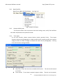
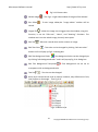
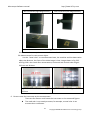
Application Program Interface Introduction
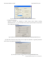
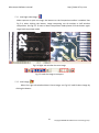
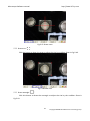
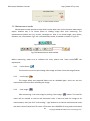
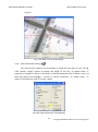
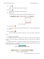
After the user use Microscope application program, it will show illustration picture in Fig.1-1. A
tool is arranged and divided into the window. The main button and file tabulate is in 3 groups,
which the left and right windows are the two sub windows. On the left window, it will show
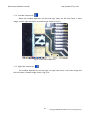
Microscope whether USB digital video device is connected. If it’s not connected the button will be a
white result as Fig.1-2 shows.
Fig.1-1 Main window picture
Fig.1-2 Connected button white
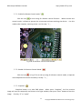
In the following, those main functions will be divided into four groups, one of the group needs to
be shown after connection is done as Fig. 1-6. These four groups are:
5
Copyright © 2008-2014 MicroLinks Technology Corp.
Microscope Software manual
http://www.ViTiny.com
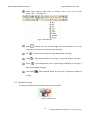
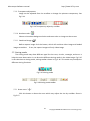
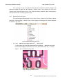
1.1 Main Toolbars
See Fig.1-3 the toolbars of the application program which commonly uses, includes File, Setting,
Window, Tool, Language and About altogether.
Fig.1-3 Main Toolbars
1.2 Main Function Buttons
Fig.1-4 are main function buttons which are commonly used or is for basic function, which
includes connecting, taking photos, saving photos, editing…etc. there are 10 functions button.
Fig.1-4 Main button group
1.3 The File List/Folder
Fig.1-5 is the tabulate of the saved images in the application program. The main list will list the
files in the existing folder, which includes BMP folder, JPG folder and AVI folder.
Fig.1-5 File List
1.4 Mode Functions
After opening Microscope program and connected as shown in Fig. 1-6, mode functions
toolbar will show under the left side of sub-window, these are mode functions.
Fig.1-6 software
connecting
6
Copyright © 2008-2014 MicroLinks Technology Corp.
Microscope Software manual
http://www.ViTiny.com
2. Main Toolbars
The tool arranges the group and pursues to show, which include file, setup, window, tool,
Language and select greatly about 5 of the choices altogether.
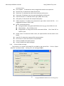
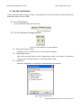
2.1 File
In the beginning, “File” is used for users who want to open/save file from other path or
Print setting...etc see Fig.2-1.
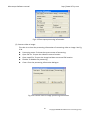
Fig.2-1 Choose file
2.1.1 Open File
Here are three types of file formats in the Open File, Bmp, Jpg and Avi as optional.
The default route for the open file folder is according to the current preserving file format.
About tabulates of the file folders, please refer to Section 3.1 for more detailed information.
In short, please refer to below Fig.2-2, if the preserving photo is in Bmp tabulate, the open
file route is for preserving Bmp photos. If the preserving photo is in Jpg tabulate, the open
file route is for preserving Jpg photos. If the preserving video is in Avi tabulate, the open file
route is for preserving Avi videos. Ctrl +O are a fast key.
Fig.2-2 Open bmp file
2.1.2 Save File
There are only Bmp and Jpg file type; the saved file is the image taken in the left
sub-window, see Fig.1-1. The storing file name is named by the program automatically; the
user can change the name by themselves. File name is in year (yyyy), month(mm), day(dd),
hour(hh), minute(nn), second(ss), serials numbers(so). Bmp_20080829180445_00001
7
Copyright © 2008-2014 MicroLinks Technology Corp.
Microscope Software manual
http://www.ViTiny.com
means 2008(yyyy) 08(mm) 29(dd) 18(hh) 04(nn) 45(ss), 00001(so), the 00001 (so) means the
first picture on 2008/08/29. The serial numbers will return to 00001 every day. In this way
the file name won’t repeat and also easy to realize the photo taken information.
Fig.2-3 Save file
2.1.3 Printer Setup
Set up printer can adjust paper between size, source or printer type.
Fig.2-4 Setup printer
2.1.4 Print Picture
Ctrl+P are a fast key.
Fig 2-5 Print
8
Copyright © 2008-2014 MicroLinks Technology Corp.
Microscope Software manual
http://www.ViTiny.com
2.1.5 Exit
Once to choose to exit, the program would close.
Ctrl+E are a fast key.
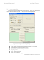
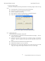
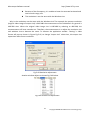
2.2 Setting
The Setting function is mainly to set up Video Format and JPG compression quality as
Fig.2-6 shows. If Microscope device isn’t at the line, video format and video signal source
unable to set up (setting in white bar); it can set up on the contrary.
Fig.2-6 Select Setting
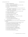
2.2.1Input Devices Setting
Optional Input Devices, see Fig.2-7, when there are 2 or more Input Devices
connecting to PC at the same time, you can choose which device you wish to use.
Fig.2-7 Optional Input Devices
2.2.2Video Format
Video Format is mainly to set up the frame rate, color space and output size etc. Fig 2-8 is the
Video Format of built in UVC Driver contents. Frame rate is frame numbers per second (fps) for
playing. Adjust the output size will slower or faster the fps, for example, if the fps is higher, the
preview video will be less clearly but with smooth performance. On the contrary, if the fps is
lower, the image will be more clear but with a little lagging performance. This is due to the more
frames requires the more CPU loading then cause the lagging performance.
9
Copyright © 2008-2014 MicroLinks Technology Corp.
Microscope Software manual
http://www.ViTiny.com
Fig.2-8 Video format contents before installing MICROSCOPE driver
2.2.3Video Format Source
Fig.2-9a & Fig.2-9b are Properties of Video Format source without installing
MICROSCOPE driver, i.e., it uses Windows’ built-in driver. Fig.2-9a Video Proc Amp allows
User to adjust the parameter.
Fig.2-9a Table of Video Proc Amp content without after installed MICROSCOPE driver
Fig.2-9b Table of Camera Control allows User to adjust the parameter. In generally, Windows
built-in driver only support limited functions.
Fig. 2-9b Table of Camera Control without installing MICROSCOPE driver
10
Copyright © 2008-2014 MicroLinks Technology Corp.
Microscope Software manual
http://www.ViTiny.com
2.2.4 Video Compressor
Normally, the video size is huge before compressor. We can use Compressor function
to reduce the file size. Fig. 2-10 shows the options for compressor. There are optional
Compressors which are built-in or can be installed by DivX Plus Codec Pack or other tool.
Once the installation is completed, you can see them at the optional Compressors.
Fig 2-10 Optional Compressor
2.2.5 JPG Quality
User can choose different JPG quality. The JPG compressor could distorted the
saved image in order to meet the saving size, in this situation, when the saved quality is low,
the image quality could be low and the file size is low too. See Fig.2-11。
Fig 2-11 Setting JPG Qualiy
2.2.6Auto-Save
From “Setting->Auto- Save” shown Fig.2-12, after checked auto-save, when clicking
the save buttons it will not show the save dialog. The system will generate a file name and
auto-save the file.
Fig 2-12 Auto-save option
11
Copyright © 2008-2014 MicroLinks Technology Corp.
Microscope Software manual
http://www.ViTiny.com
2.2.7 MJPG Preview 2M
When function MJPG preview 2M enabled, the resolution will automatically choose
1600*1200 (2MP). To enable MJPG preview needs to disconnect the device firstly.
See fig 2-13.
Fig 2-13 MJPG Preview function
2.3 Window
The Windows can be chosen per USER’s preferred window size. But it need depend on
User’s PC to choose a suitable resolution as Fig.2-13. For example, your PC is 1280*960 pixels;
you can choose 1280*960. When the PC screen size is wide screen (16:9), it may cause
imbalance ratio at “Full Screen” mode. The user may choose “Full Screen (4:3)” for an equally
true ratio. When in “Video Resolution” mode, the window size is same as the output size.
Please refer to 1.2.2. “Device control toolbar” only shows the tools for device control. Users
could preview the image by other application. Please refer to section 5.5. When choose
“Video Resolution”, the window size will become the same resolution users set in the “Video
Format”. If the resolution is higher than screen size, press “Ctrl” and click mouse left to move
the preview window. (ex: set 1600*1200 resolution in video format > screen size 1280*1024,
then move the preview window to see whole image.)
Fig 2-14 Optional window size
12
Copyright © 2008-2014 MicroLinks Technology Corp.
Microscope Software manual
http://www.ViTiny.com
User can choose full screen under window mode as shown in Fig. 2-15. The original left
sub-window in the software will become a single window, available tool bar of the
connection (disconnection), snapshot, video recording and video playing under the full screen.
Fig 2-15
Full screen of 640*480 under Window mode
If changing to single window and want to return to normal mode, please click “Normal
Mode button” see Fig.2-16
Fig 2-16 Normal Mode
13
Copyright © 2008-2014 MicroLinks Technology Corp.
Microscope Software manual
http://www.ViTiny.com
Click snapshot button and will pop up Fig.2-17, it provides function of Open file, Save file, Delete
image, Image process and Print image.
Fig 2-17 Image View of window
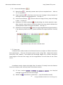
2.4 Tool
Use the Tool to open file and Time Lapse functions..etc. See Fig 2-18.
Fig 2-18 Tool functions
14
Copyright © 2008-2014 MicroLinks Technology Corp.
Microscope Software manual
http://www.ViTiny.com
2.4.1 Open Data file
Open files at BMP, JPG & AVI folder. See Fig 2-19.
Fig.2-19 Open file folder
2.4.2
Restore default path
The function allows User to preserve the initial setting route, easily find and Save
the video and photos at the preserved route.
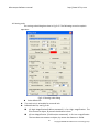
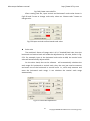
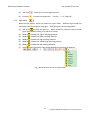
2.4.3 Time Lapse
To use this function, please connect device (under preview) firstly. Time Lapse
function allow to set photography or video record time for certain period; then convert
image to video or video to image to shorten the total time of photography. See Fig
2-20, the function setting as below:
Fig 2-20 Time Lapse setting dialogue
Start time:To set the start time to enable the function. The unit can be second
or minute.
Time Interval:To set time to capture image or video. The unit can be second,
15
Copyright © 2008-2014 MicroLinks Technology Corp.
Microscope Software manual
http://www.ViTiny.com
minute or hour.
File numbers:To decide how many image/video needs to be captured.
Record Time: To decide the video record time.
Total time: To calculate the total time to execute the function.
Save scale: To decide to save the scale when BMP or JPG format.
Save file format as: To decide the file type. (BMP, JPG or AVI)
JPG quality: To decide the JPG compressed quality.
Video compress: To choose the compressor type when record AVI file. It is
suggested to choose “DivX Codec”.
Folder name and position:
Auto-generated: Auto generated folder name by yyyy-mm-dd-hh-min-sec.
Manual Keyin:Key in folder name
Assign folder: To assign the file save into certain folder. Click “Save file” to
choose route.
Folder name: To show the folder name, the captured files will be saved in this
folder.
Save file: To choose the captured file saving location.
File save at: To show the location of saved folder.
Execute: Enable time lapse function.
Cancel: Disable time lapse dialogue.
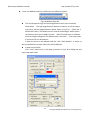
2.4.4 Convert Video to Image
This function is to convert AVI video file into BMP or Jpg picture files. Click on “Open
video file” to choose video. See Fig 2-21, the setting dialogue.
16
Copyright © 2008-2014 MicroLinks Technology Corp.
Microscope Software manual
http://www.ViTiny.com
Fig 2-21 Covert video to image setting dialogue
Open video file: To choose the video file.
File name: To show the selected video file name.
File source: To show the selected video file location.
Total frame: Total fame numbers of the video.
Total time: Total time of video.
Total files: Total file types which convert from video.
Time interval: To set the time of convert video to image by per frame, per
minutes or per second.
Transfer file: To choose the picture type. (BMP or JPG)
JPG Quality: To decide the JPG compressed quality.
Folder name and position:
Auto-generated: Auto generated folder name by yyyy-mm-dd-hh-min-sec.
Manual Keyin:Key in folder name
Assign folder: To assign the file save into certain folder. Click “Save file” to
choose route.
Folder name: To show the folder name, the captured files will be saved in this
folder.
Save file: To choose the captured file saving location.
File save at: To show the location of saved folder.
Execute: Enable time lapse function.
Cancel: Disable time lapse dialogue.
17
Copyright © 2008-2014 MicroLinks Technology Corp.
Microscope Software manual
http://www.ViTiny.com
2.4.5 Convert Image to Video
This function is to convert BMP or JPG pictures into video. To use Time Lapse function
capture and combined files into video. See Fig 2-22 and the setting dialogue.
Fig 2-22 Covert image to video setting dialogue
Frame rate(fps) : Frame per second, the picture numbers in each second.
Preview direction: Preview in forward or reverse.
Source format: To choose the file type to convert.
Play: Play pictures.
Pause:Pause pictures play.
Stop:Stop play pictures.
18
Copyright © 2008-2014 MicroLinks Technology Corp.
Microscope Software manual
http://www.ViTiny.com
Repeat:Repeat play pictures.
Open file:To choose the location of pictures.
Save file:To choose the saving location after pictures convert to video.
File source:The opened video file location.
File saved at” To choose the file saved location.
File name:
Auto-generated: Auto generated folder name by yyyy-mm-dd-hh-min-sec.
Manual Keyin:Key in folder name
Compressed Status:To decide whether to use compressor. It’s suggested to
use DivX to compress high quality of file.
File name: To show the generated file name after converted into video.
Total files:Total file numbers.
Unselected files: Numbers of unselected files.
Selected files: Numbers of selected files.
Select: Select files. Multiple selection is available.
Select all:Select all files.
Deselect:Deselect the selected file, multiple selection is available.
2.4.6
Deselect all: Deselected all files.
Reset: Return to original select status.
Execute: Enable image convert video function.
Cancel: Close the image convert video function dialogue.
Processing information
To show the Time Lapse, Image convert video or video convert image processing status.
(1) Time Lapse
The tabs is to show all Processing information about Time Lapse, see Fig 2-23:
Function status: To know the function is enabled or disabled.
Save file format as: To know the capture file type.
Start time: Count down until “0” to enable this function.
Record time: To show the capture time from begin til now.
File number: The current capture file numbers.
Total time: Count down until “o”, to disable this function.
Time interval: Count down until “1”, capture next file.
Open saved file: To open the captured files saving location.
Enable: Enable or Disable the function.
Close: Close the processing information dialogue.
19
Copyright © 2008-2014 MicroLinks Technology Corp.
Microscope Software manual
http://www.ViTiny.com
Fig 2-23Time Lapse processing information
(2) Convert video to image:
This tabs is to show the processing information of converting video to image. See Fig
2-24.
Processing status: To show the current status of converting.
Open file list: To open the video file source location.
Open saved file: To open the image had been converted file location.
Disable: To disable the processing.
Close: Close the processing information dialogue.
Fig 2-24 Convert video to image processing information
20
Copyright © 2008-2014 MicroLinks Technology Corp.
Microscope Software manual
http://www.ViTiny.com
(3) Convert image to video
This tabs is to show the processing information of converting image to video. See Fig
2-25:
Processing status: To show the current status of converting.
Open file list: To open the image file source location.
Disable: To disable the processing.
Open saved file: To open the video had been converted file location.
Close: Close the processing information dialogue.
Fig 2-25 Convert image to video processing information
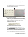
2.4.7 Measurement Info
Show measurement information, see fig 2-26.
Save measurements: Choose Save measurement before save images. (refer to
Section 5.4.3 Save Image)
Additional information: Auto-calculate Sum, Arithmetic Average, and Standard
Deviation. Note: the measure tool style and scale information must be the
same.
Stay on top: Keep the measurement info window on top.
Output format: output in .txt, xls, or xlsx files.
Measurement file and file path: Right-click on any files from the list to load
image, open image, delete images or double click on files to load image.
21
Copyright © 2008-2014 MicroLinks Technology Corp.
Microscope Software manual
http://www.ViTiny.com
Fig 2-26 Measurement Info
2.4.8 View image
Review image from list, see Fig 2-27.
Fig 2-27 Review image
22
Copyright © 2008-2014 MicroLinks Technology Corp.
Microscope Software manual
http://www.ViTiny.com
2.5 Language
The version includes multi-languages; English, Traditional Chinese, Simplified Chinese.
The initial language will automatically follow up User’s OS system. It can choose the other
language, too.
Fig. 2-28 Select language
2.6 About
Show the Microscope relevant information.
Fig 2-29 About
Learn the application program version.
Fig 2-30 About Microscope
23
Copyright © 2008-2014 MicroLinks Technology Corp.
Microscope Software manual
http://www.ViTiny.com
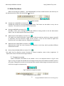
3. Main Function Buttons
Main function button group see Fig.1-4 which are commonly used or basic function, which
includes connecting, taking pictures, saving, editing…etc. there are 10 functions button.
3.1 Connect/Disconnect
3.1.1
Connect
The connect icon is as Fig.3-1, the user will connect the line while pushing the
connect button, namely connect with MICROSCOPE device. If it cannot connect, please
reinsert MICROSCOPE device to the other USB port.
Fig.3-1 Connect button icon
3.1.2
Disconnect
The button icon which shows disconnect is like Fig.3-2, by clicking this button to
disconnect. When the user starts to play the video, MICROSCOPE will be disconnected
automatically. When re-connecting the MICROSCOPE with the software , the video format
will go back to the default value.
Fig.3-2 Disconnect button icon
3.2 Snapshot
Snapshot icon is as Fig.3-1, the function allows taking a photo in Preview, Video & Play,
and image size depends on Video Format source, i.e. Height & Width.
Fig 3-3 Snapshot button icon
3.3 Save Image
Save image icon is as Fig.3-4, the saved file name is automatically created. The detail of
the file name is as description 1.1.2.
24
Copyright © 2008-2014 MicroLinks Technology Corp.
Microscope Software manual
http://www.ViTiny.com
Fig 3-4 Save image button icon
3.4 Edit the Picture / Exit Editor's Picture
3.4.1Edit Picture
The editor is as Fig.3-5 including several convenient functions. When clicking editor
icon as Fig.3-5, the toolbar for editing image will show up as Fig.3-6
Fig 3-5 Editor icon
Fig.3-6 Editor tool
The editing toolbars are upper roll and button roll.
Please click the original fit(
) first then start to use the button roll tools. The edit text,Brush
style and Draw style fucntions are only available until the original fit
Fig.3-7 Click (
When click the edit text (
edit background color (
has been selected.
) to start editor tool
) butoon, see Fig.3-8, the edit text group includes Edit text color(
), edit background color transparent (
),
).
25
Copyright © 2008-2014 MicroLinks Technology Corp.
Microscope Software manual
http://www.ViTiny.com
Fig.3-8 Click (
When click select (
) to start text tool
) button and use mouse to draw the range, the select group tools are
available as Fig.3-9. The select tools includes cut (
Fig.3-9 Click (
), copy (
), paste (
), save select (
).
) to start other functions
“Editor Image” toolbar includes many functions, below will explain each function:
Normal
:When this button is clicked, all the buttons will return to
normal.
:When the “original fit
Move Image
” button begins using, select
“Move Image” and click mouse of left button to move on
the image.
New File
:“New file” can open a blank page of image, image size is
400*300 by the Fig. 1-1 of the right side window size.
Save Image
:Save Fig.1-1 is right side window of image.The image size
by video formal of output size.
Rotate Left
:Image can rotate left 90 degree.
:Image can rotate right 90 degree.
Rotate Right
Fit The Window
:This function can let image to fit the window size.
When selecting this function, it cannot use “edit text”, “select”, and “drawing”
functions.
Zoom In
:Enlarg image without interpolation therefore if the scale
26
Copyright © 2008-2014 MicroLinks Technology Corp.
Microscope Software manual
http://www.ViTiny.com
larger
than orginal size distortion will appare.
Zoom Out
:To shirk image.
Rndo
:To go back the movemenet and only can use up to 3 times.
Redo
:To go to next movemenet and only can use up to 3 times.
Line style
: Different line styles to choose, such dot, dash-dot…etc.
See Fig 3-10.
Fig.3-10 Choose line styles
Color
:To choose pen’s “color” click on the color button and it will pop
up Fig. 3-11 dialog box.
27
Copyright © 2008-2014 MicroLinks Technology Corp.
Microscope Software manual
http://www.ViTiny.com
1.2
1.4
1.6
1.8
0.7
0.9
1.1
1.3
1.5
1.7
1.9
2.1
2.3
2.5
2.7
2.9
3.1
3.3
3.5
3.7
3.9
4.1
4.3
4.5
4.7
4.9
5.1
5.3
5.5
5.7
5.9
6.1
6.3
6.5
6.7
6.9
mm
Fig.3-11 Choose color
0.9
1.1
1.3
1.5
1.7
1.9
2.1
2.3
2.5
2.7
2.9
3.1
3.3
3.5
3.7
3.9
4.1
4.3
4.5
4.7
4.9
5.1
5.3
5.5
5.7
5.9
6.1
6.3
6.5
6.7
6.9
1
2
3.2
3.4
3.6
3.8
3
2
1
6.2
6.4
6.6
6.8
3
4.2
4.4
4.6
4.8
4
5.2
5.4
5.6
5.8
4
5.2
5.4
5.6
5.8
5
4.2
4.4
4.6
4.8
5
6.2
6.4
6.6
6.8
6
3.2
3.4
3.6
3.8
0.8
7
2.2
2.4
2.6
2.8
1.2
1.4
1.6
1.8
0.6
0.8
0.6
0.8
2.2
2.4
2.6
2.8
1.2
1.4
1.6
1.8
1
2.2
2.4
2.6
2.8
2
3.2
3.4
3.6
3.8
3
4.2
4.4
4.6
4.8
4
5.2
5.4
5.6
5.8
5
6.2
6.4
6.6
6.8
0.9
1.1
1.3
1.5
1.7
1.9
2.1
2.3
2.5
2.7
2.9
3.1
3.3
3.5
3.7
3.9
4.1
4.3
4.5
4.7
4.9
5.1
5.3
5.5
5.7
5.9
6.1
6.3
6.5
6.7
6.9
6
0.7
0.9
1.1
1.3
1.5
1.7
1.9
2.1
2.3
2.5
2.7
2.9
3.1
3.3
3.5
3.7
3.9
4.1
4.3
4.5
4.7
4.9
5.1
5.3
5.5
5.7
5.9
6.1
6.3
6.5
6.7
6.9
0.8
1.2
1.4
1.6
1.8
2.2
2.4
2.6
2.8
3.2
3.4
3.6
3.8
4.2
4.4
4.6
4.8
5.2
5.4
5.6
5.8
6.2
6.4
6.6
6.8
7
6
7
2
3
4
5
6
7
:The Fig.1-1 right side window of image will be deleted.
Delete Image
:To exit image editor,the “image editor” toolbar will be
Exit Editor
closed.
Orignal Fit
:When the image size is bigger than the window, using this
function, it can do “Edit text”, “select”, and “drawing” functions. The
window won’t see the whole image, but only some parts.
Edit Text
:Edit text is words that can be written on image.
Edit Text Color
:Text color can be changed by clicking “edit text color”
button and it will pop up Fig.3-11 dialog box.
Edit Text Background Color
:Text background color can be changed just
by clicking “edit background color” and it will pop up Fig.3-11 dialog box.
Edit Text Background Transparent
:Text background can be set as
transparent with no background color.
Text Size
:Text size can be changed.
Brush style: Various brush style to choose, however, only effective on Circle,
Oval, Square or Rectangle. See Fig 3-12.
Fig 3-12 Brush Style
28
Copyright © 2008-2014 MicroLinks Technology Corp.
Microscope Software manual
http://www.ViTiny.com
Draw Style: Various draw style to choose, such as Pen, Line, Circle,
Ellipse…etc. See Fig 3-13.
Fig 3-13 Draw Style
Select
:Selects the area on the image, after the selection, it can cut,
copy, paste, and save the selection area function.
Cut
Copy
Paste
:Cut frame on the Fig.1-1 right side window of image.
:Copy selected frame on the Fig.1-1 right side window of image.
:Paste whats been cut or copied image to display on the Fig.1-1
right side window of image.
Save Select
:Save selected frame on the Fig.1-1 right side window of
image.
3.4.2 Exit Editor’s Picture
The editor’s toolbar will close when exit the piture eidtior.
Fig.3-14 Editor icon
29
Copyright © 2008-2014 MicroLinks Technology Corp.
Microscope Software manual
http://www.ViTiny.com
3.5 Delete Image
The delete image is the image in right-sub-window(please refer to 1.1). See Fig 3-15.
Fig.3-15 Delete image icon
3.6 Video recording / Stop Video Recording
3.6.1 Video Recording
Press video recording icon see Fig.3-16 and firslty name the file name, the file name
is automatically created as Section 1.1.2. If you wish to change the file path, please refer to
Section 3.2.3. If you need to compress the file size, please refer to Section 1.2.3
Fig.3-16 Video recording icon
3.6.2 Stop Recording
Fig.3-17 Stop recording icon
3.7 Video Playing / Stop Playing video
3.7.1 Video Playing
The recorded video will plays at left window as Fig.1-1. Once it palys, the microscope
is automatically disconnected.
Fig.3-18 Film playing icon
30
Copyright © 2008-2014 MicroLinks Technology Corp.
Microscope Software manual
http://www.ViTiny.com
When play the films, Fig 3-19 toolbar will show under the preview window.
Fig.3-19 Toolbar of film playing
Play “
”: Press the button can play video.
Pause “
”: Press the button can pause video.
Stop “
”: Press the button can stop video.
Repeat “
Exit “
”: Press the button can repeat play video.
”: Press the button can exit video mode.
No Flip “ ”:Video image’s flip direction, does not makes any flip shown
in Fig.3-20.
Fig.3-20 Video image with no flip
Vertical Flip “
”:The video image upside down 180 degree, which is
vertical flip, shown in Fig.3-21.
Fig.3-21 Video image do vertical flip
Horizontal Flip “ ”:The video image left and right mirror 180 degree flip
which is horizontal flip shown in Fig.3-22.
31
Copyright © 2008-2014 MicroLinks Technology Corp.
Microscope Software manual
http://www.ViTiny.com
Fig.3-22 Video image do horizontal flip
Vertical and horizontal Flip “
”:The video image will do horizontal and
vertical flip shown in Fig.3-23.
Fig.3-23 Video image becomes horizontal flip
Click right of mouse to show Fig.3-24
Fig.3-24
3.7.2 Stop playing
Once it stops play, the microscope is still disconnected.
Fig.3-25 Stop playing icon
3.8 Edit Image / Exit Image Editor
32
Copyright © 2008-2014 MicroLinks Technology Corp.
Microscope Software manual
http://www.ViTiny.com
3.8.1Image Editor
Image processing editor as Fig.3-26, microscope software
simple image processing editing functions.
provides users few
Fig.3-26 Image Editor Icon
While clicking the Image editor icon, the image processing function buttons as Fig.3-27 will show
up on the right sub-window Fig.1-1.
Fig.3-27 Toolbar of Image Processing
Fig.3-28 Tool of Image Editor Once it clicks black and white
or inverse
it can
set up the value. The image will be changed, too.
Fig.3-28 Changing Threshold
Original Image “
Gray Level “
”:This button can let image return to original image.
”:This button can let the image from color change to gray.
Highlight Edge “
”:This button can let the image show it’s highlight
edge.
Highlight Pxiel “
”:This button will strengthen in the picture between
the different pixels.
Black/White “
”:This button can let the image from color turn to black
and white.
Inverse “
Exit “
”:This button can let the image become inverse.
”:This button is to exit video mode.
33
Copyright © 2008-2014 MicroLinks Technology Corp.
Microscope Software manual
http://www.ViTiny.com
3.8.2Exit Image Editor
Fig.3-29 Leave Image Editor
3.9 Print Image
Fig.3-30 Printing image
3.10 Exit Application Program
Fig 3-31 Exit the Application Program
34
Copyright © 2008-2014 MicroLinks Technology Corp.
Microscope Software manual
http://www.ViTiny.com
4. The File List/Folders
The file tabulates pages and signs as Fig.1-5, file tabulates is to list all file folders, which includes JPG
folder, Bmp folder, and Avi Folder.
4.1 The File Tabulates
Fig.4-1 tabulate for BMP, JPG & AVI files
Fig.4-1 File tabulates
4.2 The File Tabulates On Page Number
Fig.4-2 The file tabulates on page number
4.2.1 Show the number of pages
001/001= X/ Y, X is sequence and Y is total number of pages.
4.2.2 Change page button
Fig.4-2 left and right button can be change page number. Left button is to decrease
page number and right button is to increase page number.
4.2.3 Image Path
Click the “Image Path” to show Fig.4-3 and choose the file director
Fig.4-3 Data Path Director
35
Copyright © 2008-2014 MicroLinks Technology Corp.
Microscope Software manual
http://www.ViTiny.com
4.3 Quick Click
Click the mouse right on any image or video list, the dialogue should pop out to open file,
delete file or delete all files. See Fig.4-4.
Fig.4-4 Quick click
36
Copyright © 2008-2014 MicroLinks Technology Corp.
Microscope Software manual
http://www.ViTiny.com
5. Mode Functions
When connecting the software with MICROSCOPE, the four mode functions will show up on
the button position under left sub-window, see Fig.5-1.
Fig 5-1 Mode toolbar
Comparison mode{Refer to section 5.1}
:
Comparison mode can do overlapping two frame. The frame can be whole or any size to
compare. This mode can see two frams of simiarities.
Aiming mode{Refer to section 5.2}
:
Provides a cross, area, rectangle and circular different aiming mode to aim the observation
object .That can help capture observation object.
Video control mode {Refer to section 5.3}
:
The mode can control left hand or right hand to hold the machine, which can capture yourself
or opsiticles, but the directions might not be correct. It can use the mode to adjust the
dirctions and it can adjust contrast, brightness and exposure.
Measurement mode {Refer to section 5.4}
:
Measurement mode has ruler functions to measure at real time, which provides different
measurement tools.
Device Control Mode {Refer to section 5.5}
:
This mode has far distance control function to control snapshot, zoom in/out, brightness 具
adjustmnet from PC without touching the device.
5.1 Comparison mode
When connected, the defult of the toolbar is set as to compare shown in Fig.5-2 and
Fig.5-3. In Fig.1-6 right sub-window has no image so some part of the buttons wouldn’t work in
this mode. Comparesion mode can be overlap with another video image to compare and to cut
half of the image for comparession.
Fig.5-2 Default comparison mode
Fig.5-3 Comparison mode toolbar
37
Copyright © 2008-2014 MicroLinks Technology Corp.
Microscope Software manual
http://www.ViTiny.com
5.1.1 Load right side image “
”
When capture or open one imge, the buttons on the Comparison toolbar is enabled. See
Fig 5-4, when clicking the button, image comparing can do overlap or half window
comparison. See Fig.5-5. If want to leave comparison mode please click the button again
to go back to preview mode.
Fig.5-4 Right sub-window has one image
Fig 5-5 Load the image to compare
5.1.2 Load image “
”
When the right sub-window doesn’t have image, see Fig.5-6, load & select image by
clicking the button.
38
Copyright © 2008-2014 MicroLinks Technology Corp.
Microscope Software manual
http://www.ViTiny.com
Fig.5-6 Load image button
Click the button. After opened the file, it can use overlap and cut half image function. See
Fig.5-7, to exit the image comparison, just click the original button again to go back to
preview mode.
Fig.5-7 After loading image
5.1.3 Overlap comparison “
”
The “overlap comparison” can makes the image transparence. With overlap in the
video image, then at the same time shows two frames. Show in Fig.5-8.
Fig.5-8 Overlap comparison
39
Copyright © 2008-2014 MicroLinks Technology Corp.
Microscope Software manual
http://www.ViTiny.com
5.1.4 Left side comparison “
”
When the window separates into left and right sides, the left side frame is video
image, and the right side frame is loaded image. Show in Fig.5-9.
Fig. 5-9 Left side comparison
5.1.5 Right side comparison “
”
The window separates to left and right, the right side frame is the video image and
left side frame is loaded image. Show in Fig.5-10.
40
Copyright © 2008-2014 MicroLinks Technology Corp.
Microscope Software manual
http://www.ViTiny.com
Fig.5-10 Right side comparison
5.1.6 Top side comparison “
”
Window separates into two half which is top and bottom. Top is video image, and
bottom is loaded image. Show in Fig.5-11.
Fig.5-11 Top side comparison
41
Copyright © 2008-2014 MicroLinks Technology Corp.
Microscope Software manual
http://www.ViTiny.com
5.1.7 Bottom side comparison “
”
Window separates into two half, bottom side is video image, and top side is loaded
image. Show Fig.5-12.
Fig.5-12 Bottom side comparison
5.1.8 Window size/Image direction
When choose half window compare, the scrollbar as Fig 5-13a is to adjust the
preview v.s. load image ratio. If “
of loaded image. If the “
” is not clicked on, it means to adjust the ratio
” is clicked, it is to adjust the image position of the
loaded image. See Fig 5-13b.
Fig 5-13awindow ratio adjustment
Fig 5-13bimage position adjustment
42
Copyright © 2008-2014 MicroLinks Technology Corp.
Microscope Software manual
http://www.ViTiny.com
5.1.9 Transparent adjustment
Image can be adjusted from the scrollbar to change the pictures transparency. See
Fig 5-14.
Fig.5-14 Transparency adjust by scrollbar
5.1.10 Knockout color “
”
Choose to knockout background color and some color on image can be cut out.
5.1.11 Combined image “
”
Before capture image click the button, which will combine video image and loaded
image to combine. If not, the capture images will only video image.
5.2 Aiming mode
The aiming mode may draw different type like the cross, circular, rectangle, and area. It
helps the user observation. It can draw the different aiming mode in the video image. Fig.5-15
is the selection to aiming mode, aiming toolbar shown in Fig.5-16. This mode may overlap the
different aiming functions.
Fig.5-15 Aiming mode
Fig.5-16 Aiming mode toolbar
5.2.1 Draws cross “
”
Click this button to draw the cross which may adjust the size by scrollbar. Show in
Fig.5-17.
43
Copyright © 2008-2014 MicroLinks Technology Corp.
Microscope Software manual
http://www.ViTiny.com
Fig.5-17 Draws cross
5.2.2 Draw area “
”
Click the button to draw the area to adjust the size by scrollbar. Show in Fig.5-18.
Fig.5-18 Draw area
5.2.3 Draw rectangle “
”
Click this button to draw the rectangle to adjust the size by the scrollbar. Show in
Fig.5-19.
44
Copyright © 2008-2014 MicroLinks Technology Corp.
Microscope Software manual
http://www.ViTiny.com
Fig. 5-19 Draw rectangle
5.2.4 Draw Circular “
”
Click this button to draw circular to adjust size by scrollbar. Show in Fig.5-20.
Fig.5-20 Draw Circular
5.2.5 Choose the color of aim point “
”
Click this button, will pop up choose color dialog box and from there to choose color.
5.2.6 Clear aim point “
”
To clear all aiming lines on fame
45
Copyright © 2008-2014 MicroLinks Technology Corp.
Microscope Software manual
http://www.ViTiny.com
5.3 Video control mode
This toolbar has the functions to flip video image. The image will presented upside down
as well as the image moving direction when holding by different hand. By the mode, it can
preview the correct direction. The brightness, contrast and exposure tool can be adjusted and
also can cause the video image to be clearer in different scene. Fig.5-21 is the selection video
control mode. Fig.5-22 is the toolbar of video control mode.
Fig.5-21 Video control mode
Fig.5-22 Video control mode toolbar
5.3.1
No Flip “
”
Video image’s flip direction, does not makes any flip shown in Fig.5-23
Fig.5-23 Video image with no flip
5.3.2
Vertical Flip “
”
The video image upside down 180 degree, which is vertical flip, shown in Fig.5-24.
Fig 5-24 Video image do vertical flip
5.3.3
Vertical and horizontal rotation
“
”
The video image reverse between left & right for 180 degree flip which is horizontal
flip shown in Fig.5-25.
46
Copyright © 2008-2014 MicroLinks Technology Corp.
Microscope Software manual
http://www.ViTiny.com
Fig 5-25 Image of vertical and horizontal rotation
5.3.4
Horizontal rotation “
”
The video image will do horizontal and vertical flip shown in Fig.5-26.
Fig 5-26 Image of horizontal rotation
5.3.5
Adjust Brightness “
”
To adjust brightness is to click on the brightness button. By scrollbar adjust
brightness. If want to default just click it again.
5.3.6
Adjust Contrast “
”
To adjust contract just click the contrast button which can adjust by the scrollbar. If
want to default just click it again.
5.3.7
Adjust Exposure “
”
When adjusting the exposure, click on the exposure button and to default just click it
again. If this button cannot click, it means the driver doesn’t support this function. If
adjust has no response, then go to “setting->video source” it will pop up shown Fig.
5-27. Please check this option if wish the function to be active. If this option doesn’t
shown on the page, it means the driver doesn’t support this function.
47
Copyright © 2008-2014 MicroLinks Technology Corp.
Microscope Software manual
http://www.ViTiny.com
Fig. 5-27 auto mode control
5.4 Measurement mode
Measurement mode provide a scale which can be draw ruler and to measure observation
object. Another way is to Freeze frame or loading image after then measuring. The
measurement toolbar has line, circular, rectangle etc. Also, it can show length, area, radius,
diameter, etc, information. Fig.5-28. is measurement mode; its toolbar is shown in Fig.5-29.
Fig.5-28 Measurement mode
Fig.5-29 Measurement mode toolbar
Before measuring, make sure to calibrate the scale, please note “scale setting
” the
explanation.
5.4.1
Freeze frame “
”
This function can let the previewing video image to freeze. Once the image freezes.
5.4.2
Load image “
”
The image which was captured before can be reloaded again. Users can use the
measurement function after reloading the image
5.4.3
Save image “
”
After measuring, it can save image by clicking “save image “
” button. The save file
name will be marked as vertical and horizontal scale. If want to load the image to do
measurement, then just click “scale setting” “
” button to set vertical and horizontal scale,
and these scale of value form file name. If file name has v420h560 of string means horizontal
48
Copyright © 2008-2014 MicroLinks Technology Corp.
Microscope Software manual
http://www.ViTiny.com
5.60mm and is vertical is 4.20mm.
5.4.4
Copy to clipboard “
”
Select “Copy to Clipboard” “
” button then the current frame will be copied to
clipboard ,also, it will be pasted to right side windows at Fig.1. After copying, it can be
pasted on word or excel. Etc.
5.4.5
Scale setting “
”
6. Select suitable ruler
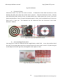
Before setting scale, first find the higher accurate ruler to measure. Use generally
ruler shown as Fig. 5-30.
Fig. 5-30 Metal ruler
e
a
b
c
d
49
Copyright © 2008-2014 MicroLinks Technology Corp.
Microscope Software manual
http://www.ViTiny.com
Fig 5-31 Calibrator
a. Concentric Circles:
Concentric Circles is to see if the ratio is correct. If Concentric Circles does not form as circle
(became like Oval,,etc) means the screen ratio is not 4:3. Place the Concentric Circles directly
onto PCB drilling hole, See Fig 5-31a, no matter black line or white space size is 1mm. First circle
(black dot) diameter is 1mm, second circle(white space) is 3mm, third circle(black line) is 5mm, the
forth circle is 7mm..,etc. The diameter can be measured from the concentric circle scale.
Diameter: 3.00mm
Fig 5-31a way to use Concentric Circles
b. 1mm Low Magnification Grid:
Low mag Grid is used for calibrate the low magnification, wider field. It can also used to check
the ratio, if the square does not form as square means the screen ratio is not 4:3. To place the grid
on the object as the bill Fig.5-31b, the length for each square is 1mm.
Fig 5-31b way to use Low Magnification Grid
50
Copyright © 2008-2014 MicroLinks Technology Corp.
Microscope Software manual
http://www.ViTiny.com
c.
Cross (High Magnfication)
The main purpose for the Cross is to calibrate the default setting in software and
also to measure. The Cross (See above chart c) has 3 kinds of units as 0.05mm, 0.1mm
and 1mm scale. It will measure 0.05mm, 0.1mm at high magnification and 0.1mm,
1mm at low magnification. The Cross can measure the Length and Width accurately,
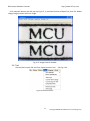
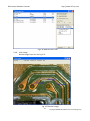
ie.: Fig.5-34, Measure the length of the onion cell as the red rectangle which is
approximate 0.400mm.
Fig 5-31c way to use Cross
d. 0.1mm High Magnification Grid
High Magnification grid is used for observing tiny object. See Fig.5-31d, put the
0.1mm scale (See above chart d) on “
0.100mm.
” microdot. The Length of
in a square i.e.
Fig 5-31d way to use High magnification Grid
e. L Type Low magnification ruler
L Type low magnification is used for calibrating or measuring low magnification.
The unit is CM, the section is 1mm.
Choose the suitable calibrator based on different observation needs, due to the
calibrator is transparent, it can place on the object then observing by microscope.
51
Copyright © 2008-2014 MicroLinks Technology Corp.
Microscope Software manual
http://www.ViTiny.com
The more precise ruler, the more accurate measurement can be obtained under high
magnification. The difference of using “metal ruler” and “calibrator”:
When the magnification is high, use the calibrator can easily and accurately
knows the scale range.
When the magnification is high, metal ruler is less accurately than a
calibrator.
When the magnification is low, a metal ruler can be suitable.
7. Calculate scale rang
First, the scale setting must calculate the horizontal and vertical scale range,
the following has several steps to decide the scale range, suggested that the
windows size adjust 640*480 the single windows:
To decide measure distance between machine and observation objects.
To adjust the focus to see the image as clear as it can.
Calculate the observation video image of horizontal and vertical scale.
Calculate the range shown in Fig.5-33.
After setup the horizontal and vertical scales, the machine, the observation
distance and focus are not allow to readjustment.
Fig.5-33 Horizontal and vertical measurement range
8. Calibrate “non-contacted” scale
Non-contacted scale: To hold the machine by the stand, fix the device lens
above calibrator or ruler for distance, it can observe as low magnification.
If the device lens is close to the calibrator, it can observe as high
magnification.
52
Copyright © 2008-2014 MicroLinks Technology Corp.
Microscope Software manual
http://www.ViTiny.com
Non-Contacted (High Magnification)
Non-Contacted (Low Magnification)
Fig.5-34 Non-Contacted
Based on the above steps it can measure horizontal and vertical scale.
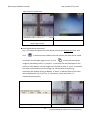
EX: Measurement for non-contact object.
Use the “metal ruler” as a measurement base, the machine and the observation
object has distance, the focus of the video image is clear. Image shown in Fig.5-35
and Fig.5-36 is the result after measurement, horizontal and vertical scale range is
24.2mm and 18.1mm.
Fig.5-35 Horizontal scale
24.2mm
range
is Fig.5-36 Vertical scale range is 18.1mm
9. Factors cause the inaccurate on the measurement
There are few factors could cause the inaccurate on the measured figures.
The used ruler is not exactly accurate, for example, a metal ruler is not
accurate than a calibrator.
53
Copyright © 2008-2014 MicroLinks Technology Corp.
Microscope Software manual
http://www.ViTiny.com
Because of the discrepancy, it is unable to know the accurate horizontal and
vertical scale range, too.
The resolution is not the same with the Windows size.
Why is the resolution not the same with the Windows size? For example the present resolution
(original video image of output size) is 640*480 the measurement of the Windows's for general is
400*300 sizes. When the original video image size is 640*480 by reducing to 400*300, the
measurements will have caused error. Therefore, the measurement is to adjust the resolution size
and windows size to become the same. To chooses the application toolbar. “Setting”-> video
format will pop up shown in Figure Fig.5-45, to change “output size” value then, this output size
expression video source resolution.
Fig.5-45 Resolution adjustment
Another window adjusts as shown Fig.5-46 below.
Fig.5-46 window size adjustment
54
Copyright © 2008-2014 MicroLinks Technology Corp.
Microscope Software manual
http://www.ViTiny.com
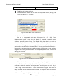
10. Setting scale
The setting scale dialog box show in Fig.5-47. The following several to explain
operation
Fig.5-47 Setting scale dialog
Scale default file
The scale unit is selectable for mm and inch.
Default Scale file, see Fig 5-48.
@ High Magnification[0.00cm,contacted]: is for High magnification. The
lens contact to object, by means the distance is 0cm.
@ Low Magnification [22.00cm,Non-contacted]: is for Low magnification.
The Lens does not contact to object, by means the distance is 22CM.
55
Copyright © 2008-2014 MicroLinks Technology Corp.
Microscope Software manual
http://www.ViTiny.com
Note: the default scale file is different from different models.
Fig 5-48 Default Scale file
The microscope has high and low magnification when non-contacted
observation. The high magnification distance is about 1.0cm from object
to the lens, the low magnification is about 14cm, as Fig 5-34. (There are 2
default scale files.) The default scale is used for fixed height, which means
the distance from lens to object is fixed. Scale file need to be re-calibrate
once the height changed or the default scale is not ideal. It can also create
a new scale file for observation.
If want to return to the default scale file, click “Scale default” to return to
the two default files and the other files will be deleted.
Create new scale file
Click “new” button than it will pop up shown in Fig.5-49 a dialog box and
input new scale name.
56
Copyright © 2008-2014 MicroLinks Technology Corp.
Microscope Software manual
http://www.ViTiny.com
Fig.5-49 Create new scale file
After creating new file, input vertical and horizontal’s scale value shown in
Fig.5-50 and if want to change scale color, select on “choose color” button to
change color.
Fig.5-50 Input vertical and horizontal scale value
Scale ratio
The machine’s Sensor of image ratio is 4:3, if checked fixed ratio, then the
horizontal and vertical scale will make the adjustment by 4:3 ratio, shown in Fig.
5-51. For example, input in the horizontal scale value to 400, the vertical scale
value will automatically adjust to 300.
On the other hand, due to the software will automatically calculate the
scale range for horizontal or vertical scale, thus, the user just need to measure
and enter one of the horizontal or vertical scale. i.e., while only measure and
enter the horizontal scale range, it can calculate the vertical scale range
automatically.
Fig.5-51 Fixed ratio adjustment
57
Copyright © 2008-2014 MicroLinks Technology Corp.
Microscope Software manual
http://www.ViTiny.com
Set ruler position & show (0,0) position
Ruler can display at Horizontal or Vertical position as per example per below
Fig.5-52 options. The image results in Fig.5-53.
Fig.5-52 Ruler vertical and horizontal
position setting
Fig.5-53 Ruler vertical and horizontal Display
To set up the horizontal effective range
As shown in Fig. 5-54, there’re two options for horizontal effective range setup.
The default setting is auto-detection which is able to define the effective display.
If the detected value is “0”, or adjustment required, the manual adjustment
function is also available. There are different unit options, cm and inch,
available in manual adjustment mode.
Figure 5-54 Setting effective horizontal dimension on monitor
When the “magnification display” is checked, as shown in Fig. 5-54, the
magnification ration will show on the upper right corner of the display window
based on display size, image resolution and preview window size. The ratio is
calculated by Field of View. Field of View is the calibrated horizontal and
vertical scale. Users could also calculate the ratio by rulers, please refer to Fig.
5-56. The displayed 1.00 mm equals to 16.2mm ruler scale, therefore, this is
58
Copyright © 2008-2014 MicroLinks Technology Corp.
Microscope Software manual
http://www.ViTiny.com
16.2 times the actual size.
Fig 5-55 The magnification ratio on the
upper right corner
Fig 5-56 measure ratio by ruler
Ratio displayed on the picture
Fig. 5-57 shows the options for ratio display. Choose the display way first, then
click 「
」in measurement mode to save the picture, the ratio will be saved
and shown on the upper right corner; or click 「
」to copy the previewed
image to previewed picture. If “monitor” is selected, the ratio displayed on the
picture is calculated by current image size and Filed of View. If “print” is selected,
the ratio is calculated by current image size, Field of View and printing
resolution (the default setting is 960dpi). If “both” is selected, both of the ratio
will be displayed as Fig. 5-58. The “S” represents screen ratio while “P”
represents printing ratio.
Fig 5-57 Setting of picture magnification
Fig 5-58 Saved ratio
59
Copyright © 2008-2014 MicroLinks Technology Corp.
Microscope Software manual
http://www.ViTiny.com
ratio display
To delete and rename scale file
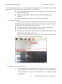
Choose delete or rename the file from the drop down menu, see Fig.5-59.
Then click “delete” or “rename”.
Fig.5-59 drop down menu choose file
Semi-Auto Calibration
Set up a customized semi-auto Calibration. See Fig. 5-60. “Input
Measurement Length” means the real length. For example, enter 400 means
4.00mm, enter 50 means 0.5mm. The Display Scale check-box is to decide to
show the Display Scale or not. If click the Horizontal Fixed, only a horizontal axis
can draw on the image; on the contrary, if click the Vertical fixed, only a vertical
axis can draw on the image. If choose “None”, axis can draw from any direction. A
horizontal or vertical axis can be draw by pressing ‘shift’ button on your keyboard
together with clicking mouse left. After it is completed, please click “Finished” for
saving the new scale.
Fig. 5-60 Input the actual measurement length
The calibration frame can be freeze by pressing the right button on the
mouse. The freeze frame helps for calibrating in a stable condition. Put the
calibrator under the machine and adjust focus to clearly see the scale. Key in
“400” length in the check-box of “Input Measurement Length”. Use mouse to
draw a yellow line for 4.00mm.Click “Finished” to complete and save the new
calibration figure.
The new setting scale (Calibration Scale [New]) show on the frame. See
60
Copyright © 2008-2014 MicroLinks Technology Corp.
Microscope Software manual
http://www.ViTiny.com
Fig.5-61.
Fig. 5-61 Draw a line in actual length
5.4.6 Scale information setting “
”
This setup screen indicates to set whether to show the unit value or not, see Fig.
5-60. Choose “length” means to display the length of the line, by capital letter “L”
expression, if length is 2.33mm, it will show L=2.33mm besides the line. If choose “none”, no
value will show on the dialogue. If show “P” means “perimeter”, “A” means “Area”, “C”
means “Circumference, and “R” means ”radius”
Fig.5-62 Scale information setting dialog
61
Copyright © 2008-2014 MicroLinks Technology Corp.
Microscope Software manual
http://www.ViTiny.com
The “precision” is refers to under the decimal point of effective number of digits. The
effective number of digits can be adjusted. “Choose color” may choose the text color.
“Display unit” does not check its unit “mm” did not display. Attention, after setting option,
and also choose the “measuring means style”.
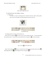
5.4.7 Measurement tool styles
The measuring include optional Line, 2 Points Circle, 3 Points Circle, Ellipse, Square,
Rectangle, 3 Points Angle, 3 Points Fillet, 4 Points Angle, and Polygon for variable demand.
As shown in Fig. 5-63.
Fig.5-63 Measurement Tool Styles
(1) Line: Measure the Length and use . See Fig 5-63.
Firstly choose Fig.5-63 Scale information setting dialog. Measure the Length
on the PCB rectangle, choose the “line” icon, then draw a line, the “ L” means
Length. Ex: L=5.510mm as Fig. 5-64.
Fig 5-64 Length measurement
62
Copyright © 2008-2014 MicroLinks Technology Corp.
Microscope Software manual
http://www.ViTiny.com
(2) Trace: Use Trace
to measure length when line is not straight.
See Fig 5-65, the total length is L=5.550mm. Right click one time to end up draw
line.
Fig 5-65 Trace measurement
(3) Multi-lines
: Measure lengths from line.
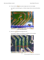
See Fig 5-66, 3 lengths are L=0.436mm, L=0.403mm, and L=0.422mm.
Right click one time to end up draw multi-lines.
63
Copyright © 2008-2014 MicroLinks Technology Corp.
Microscope Software manual
http://www.ViTiny.com
Fig 5-66 Multi-lines measurement
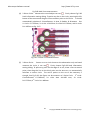
(4) 2 Points Circle: Measure the round object can use . Firstly choose Fig.5-63
Scale information setting dialog. To point any dot on the circle, pressing the left
button of the mouse and drag the line to another point on the circle. It should
automatically calculate C: Circumference, A: Area, R: Radius, D: Diameter. See
1st circle: C=2.276mm, 2nd circle: =0.412mm2, 3rd circle R=0.716mm, and 4th circle
D=1.467mm as Fig. 5-67.
Fig 5-67 2 Points Circle Measurement
(5) 3 Points Circle:
See an arc or a circle shows on the observation only and need
measure the circle, it can use . Firstly choose Fig.5-68 Scale information
setting dialog. To point any point on the edge of an arc, draw a line to second
point, then drag the line to the third point on the same arc, to automatically
calculate a correct circle. The said 3 points on the arc to be necessary a
triangle, See Fig 5-66, the figure can be measure as 2 Point Circle. 1st circle:
Circumferences C=2.409mm, 2nd circle Area A=0.450 mm2, 3rd circle:
R=0.727mm, 4th circle: D=1.480mm.
64
Copyright © 2008-2014 MicroLinks Technology Corp.
Microscope Software manual
http://www.ViTiny.com
Fig.5-68 3 Points Circle
(6) Arc: Use
to measure Arc or similar shape. There are 5 scale setting in
Arc’s scale options. See Fig 5-69, different information when measure arc.
[01]L=1.595mm
for
Arc
Length,
[02]P=5.960mm
for
circumferences,
2
[03]A=1.229mm for area, [04]R=0.963mm for radius, [05] radius, for angle.
Press “Shift” on keyboard to rotate arc, or “Ctrl” to change arc direction.
Fig 5-69 Arc measurement
(7) Arch: Measure arch can use
measure
arch.
. See Fig 5-70 different information when
[01]P=4.7mm
for
Chord
Length,
[02]A=1.0mm2
for
circumferences. Press “Shift” on keyboard to rotate arch, or “Ctrl” to change
arc direction.
65
Copyright © 2008-2014 MicroLinks Technology Corp.
Microscope Software manual
http://www.ViTiny.com
Fig 5-70 Arch measurement
(8) Oval: Measure an oval circle and use . Firstly choose Fig.5-71 Scale
information setting dialog. To point any dot on an oval, pressing the left
mouse button, and drag to fit the oval on an observation object. Same
methods as Circle to be measured for 2 Points Circle and 3 Points Circle, 1 st oval
C=6.703m, 2nd oval A=2.947mm2, 3rd oval: lR=1.328mm, sR=0.714mm, 4th oval
lD=2.826mm, sD=1.428mm.
Fig 5-671 Oval
(9) Square: To measure the object is a parallelogram, it can use . Firstly choose
Fig.5-63 Scale information setting dialog. To point one dot on the angle,
pressing the left mouse button, and drag the diagonal to make a square and fit
the observed object. See Fig 5-68 , P:Perimeter, A: Area, see Fig 5-72, the top
square on left P=7.295mm, the bottom square on left A=3.587 mm2.
66
Copyright © 2008-2014 MicroLinks Technology Corp.
Microscope Software manual
http://www.ViTiny.com
P=7.295mm, the bottom square on left A=3.587 mm2.
Fig 5-72 Square
(10) Rectangle: Measure a rectangle and use . Firstly choose Fig.5-63 Scale
information setting dialog. To point one dot on the corner, press the left
mouse button, and drag the diagonal to make a rectangle to fit the observed
object. See Fig 5-73, P:Perimeter, A: Area, see Fig 5-69, the top rectangle on
left P=10.308mm, the bottom rectangle in the middle A=1.940 mm2.
Fig 5-673 Rectangle
(11) 3 Points Angle: Measure the angle on the object and use . In Fig. 5-74, it
can see an angle on the object, draw a line and stop at the corner of angle, and
then draw the other line from the angle; the angle can be automatically
calculated. a dot shows the measured angle, it is 135.5 o.
67
Copyright © 2008-2014 MicroLinks Technology Corp.
Microscope Software manual
http://www.ViTiny.com
Fig 5-74 3 Points Angle
(12) 3 Points Chamfer: Measure charm and use . Draw first line on the angle (see
line A) and press the left mouse button to drag a line on the other side of the
angle (See line B) to calculate the chamfer. See Fig 5-75. There is a small dot
inside the chamfer and shows 45.8o.
Fig 5-75 3 Points Chamfer
(13) 4 Points Angle: Use
to measure an angle but only see 2 unparallel lines
shown on the object. See Fig 5-76, to draw a 1st line from the object (see line
A), and to draw the other unparallel line (see line B), the angle can be
automatically calculated. See Fig 5-76. There is a small dot show 45.3o.
68
Copyright © 2008-2014 MicroLinks Technology Corp.
Microscope Software manual
http://www.ViTiny.com
Fig 5-76 4 Points Chamfer
(14) Polygon:A polygon is a shape that is made up of many sides and has only line
segments. Choose “
” to measure the area and Perimeter, See Fig 5-77, the
calculated polygon P (Perimeter) is 1.992mm, A(Area) is 0.218 mm2。
Fig 5-77 Polygon
5.4.8 Draw overlap line “ ”
While selecting this function, it can be drawn many times in the fame. After clicking
“draw overlap line” undo or redo can be used show in Fig.5-78, if not selected it only can
repeat drawings.
Fig.5-78 Overlap tool
69
Copyright © 2008-2014 MicroLinks Technology Corp.
Microscope Software manual
5.4.9 Undo “
http://www.ViTiny.com
”
Undo function that can go back to the movement.
5.4.10 Redo “
”
Redo function can also go to the next movement.
5.4.11 Border styles
There are lines styles shown in Fig.5-79 and can choose different lines.
Fig. 5-79 Line styles
5.4.12 Choose color “
”
The tool can select colors to become different color. The line and background color
can’t be similar.
5.4.13 Clear Border “
”
Clear all things that are drawn on the fame. “Undo” and “Redo” record will be
erasing.
5.4 Far distance control mode
This mode is to control the machine from software directly without touching the
machine. This function allows to do photograpy, video record, zooming in/out, brightness
control…etc.
When connect software with device, the default setting is for hand-operation, thus all
buttons appears white. (unclickable) See Fig 5-80 the default far distance control mode, Fig
5-81 far distance control mode toolbar.
Fig 5-80 default far distance control mode
Fig 5-81 device control toolbar
70
Copyright © 2008-2014 MicroLinks Technology Corp.
Microscope Software manual
http://www.ViTiny.com
5.5.1 Enable Far Distant Control mode ”
Click the icon
”
, to start using far distance control function. When connect this
control mode, it allows to operate the microscope without touching the device. Use this
mode to do snapshot, zooming in/out…etc. Fast key「C」。
Fig 5-82 far distance control mode toolbar
5.5.2 Disable Far Distance Control Mode ”
Click the icon
”
in Fig 5-78, to end up using far distance control mode, to operate
microscope device function manually. Fast key「C」。
5.5.3 Snapshot “
”
Snapshot button is to take 5MP photo. When press “snapshot”, the live preview
image will save for temporally and show on the right window, then press “Save” button to save the
image. Fast key: “S” or “space”
71
Copyright © 2008-2014 MicroLinks Technology Corp.
Microscope Software manual
5.5.4
http://www.ViTiny.com
Focus and Calibration
(1) Manual focus
: Manually operate zoom in/out to complete focus. Refer to
“5.7.7”, fast key “4”.
(2) Single autofocus
:Only focus one time even if image is blurry because of
moving the object or changing distance. Fast key “5”.
(3) Continuous autofocus:
:Re-focus when the image is blurry, stop until image
is clear. Fast key “6”
(4) Calibration of whole operation
:Re-calculating the whole operation steps.
After using for some period or electricity black out occur, please calibrate the
whole operation when re-connect the power. Fast key “7”.
(5) Calibration of initial position :Return to high magnification (original position),
if the electricity black out occur, please calibrate the original position. Fast key
“8”.
Fig 5-83 Focus ways and motor calibrate menu
5.5.5 Focus area
In Manual focus mode, based on the distance from lens to object or FOV to choose the
focus area/section. There are 15 sections options. (refer to Fig 5-84) Choose one section
(ex:1.95cm, FOV 2.34mm) then adjust the microscope height as to 1.95cm, tuning the
stand height to find the clear image, and the magnification size will show on the screen
corner.
In autofocus mode, choose the height from 15 sections if already know the distance
from lens to object, and it will only focus in the chosen section.
(1) 15 focus sections:
rectangle is to show the current lens height.
(2) Whole area
the blue/red
: search focus in whole area. (only for Autofocus mode)
72
Copyright © 2008-2014 MicroLinks Technology Corp.
Microscope Software manual
http://www.ViTiny.com
(3) Current Section:
autofocus)
: search the section based on current position. (only for
Fig 5-84 Drop down menu for focus
5.5.6 Manual focus “
”
(1) Current position
: to show the lens position when moving, see Fig 5-78,
the track bar is also to show the current lens position.
(2) Zoom out
or “↑”.
(3) Zoom in
“↓”.
: Ascending speed when press zoom out longer. Fast key “I”, “+”,
:Ascending speed when press zoom in longer. Fast key “O”, “-“ or
(4) Step zoom out: :zoom out by one step. Fast key “W”.
(5) Step zoom in :Zoom in by one step. Fast key “E”
5.5.7 LED brightness adjustment level “
(1) LED on
/off
”
:when “off”, all LEDs turn off. When “on”, the LED will turn on
and the brightness is the same as last time before turn off. Fast key “D”.
(2) Decrease :decrease the brightness. Fast key “←” or “Page Down”.
73
Copyright © 2008-2014 MicroLinks Technology Corp.
Microscope Software manual
(3) LED levels
http://www.ViTiny.com
:Show the current brightness level.
:increase the brightness. Fast key “→: or “Page Up”
(4) Increase
5.5.8 Light mode「
」
Based on the objects, there are options for Light mode. Different Light mode can
be choose from direct light or side light. Side light gives stereo image effect.
(1) LED All on : All LEDs are light on. When enable Far Distance control mode,
Light mode default setting is in LED All on mode.
(2) Mode 1 : Suitable for higher working distance.
(3) Mode 2 : Suitable for lower working distance.
(4)
(5)
(6)
(7)
Mode 3
Mode 4
Mode 5
Auto
: Suitable for high working distance.
: Suitable for middle-high working distance.
: Suitable for low working distance.
: Auto change the light mode depends on the working distance.
Fig. 5-85 Drop down menu for Light mode.
74
Copyright © 2008-2014 MicroLinks Technology Corp.