1
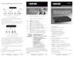
LR0304A-KIT LR0308A-KIT 4-Port and 8-Port T1/E1 Ethernet Network Extender Kits Extend Ethernet with four or eight T1/E1 connections over copper.BLACK BOX ® Bridges 10BASE-T/100BASE-TX Ethernet interface. 4-Port unit supports maximum bandwidth of 6.144 Mbps on T1 and 7.936 Mbps on E1. 8-Port unit supports maximum bandwidth of 12.288 Mbps on T1 and 15.872 Mbps on E1. Supports Ethernet Auto MDI-X function so no crossover cables are needed. Provides auto backup and recovery for Ethernet bridge connections. Customer Support Information Order toll-free in the U.S.: Call 877-877-BBOX (outside U.S. call 724-746-5500) • FREE technical support 24 hours a day, 7 days a week: Call 724-746-5500 or fax 724-746-0746 • Mailing address: Black Box Corporation, 1000 Park Drive, Lawrence, PA 15055-1018 • Web site: www.blackbox.com • E-mail: [email protected] 4-Port and 8-Port T1/E1 Ethernet Network Extender Kits Trademarks Used in this Manual Black Box and the Double Diamond logo are registered trademarks of BB Technologies, Inc. AT&T is a registered trademark of AT&T Intellectual Property II, LP. Microsoft and Windows are registered trademarks of Microsoft Corporation. Any other trademarks mentioned in this manual are acknowledged to be the property of the trademark owners. We‘re here to help! If you have any questions about your application or our products, contact Black Box Tech Support at 724-746-5500 or go to blackbox.com and click on “Talk to Black Box.” You’ll be live with one of our technical experts in less than 30 seconds. Page 2 724-746-5500 | blackbox.com FCC and IC RFI Statements Federal Communications Commission and Industry Canada Radio Frequency Interference Statements This equipment generates, uses, and can radiate radio-frequency energy, and if not installed and used properly, that is, in strict accordance with the manufacturer’s instructions, may cause interference to radio communication. It has been tested and found to comply with the limits for a Class A computing device in accordance with the specifications in Subpart J of Part 15 of FCC rules, which are designed to provide reasonable protection against such interference when the equipment is operated in a commercial environment. Operation of this equipment in a residential area is likely to cause interference, in which case the user at his own expense will be required to take whatever measures may be necessary to correct the interference. Changes or modifications not expressly approved by the party responsible for compliance could void the user’s authority to operate the equipment. This digital apparatus does not exceed the Class A limits for radio noise emission from digital apparatus set out in the Radio Interference Regulation of Industry Canada. Le présent appareil numérique n’émet pas de bruits radioélectriques dépassant les limites applicables aux appareils numériques de la classe A prescrites dans le Règlement sur le brouillage radioélectrique publié par Industrie Canada. Page 3 4-Port and 8-Port T1/E1 Ethernet Network Extender Kits Normas Oficiales Mexicanas (NOM) Electrical Safety Statement INSTRUCCIONES DE SEGURIDAD 1. Todas las instrucciones de seguridad y operación deberán ser leídas antes de que el aparato eléctrico sea operado. 2. Las instrucciones de seguridad y operación deberán ser guardadas para referencia futura. 3. Todas las advertencias en el aparato eléctrico y en sus instrucciones de operación deben ser respetadas. 4. Todas las instrucciones de operación y uso deben ser seguidas. 5. El aparato eléctrico no deberá ser usado cerca del agua—por ejemplo, cerca de la tina de baño, lavabo, sótano mojado o cerca de una alberca, etc.. 6. El aparato eléctrico debe ser usado únicamente con carritos o pedestales que sean recomendados por el fabricante. 7. El aparato eléctrico debe ser montado a la pared o al techo sólo como sea recomendado por el fabricante. 8. Servicio—El usuario no debe intentar dar servicio al equipo eléctrico más allá a lo descrito en las instrucciones de operación. Todo otro servicio deberá ser referido a personal de servicio calificado. 9. El aparato eléctrico debe ser situado de tal manera que su posición no interfiera su uso. La colocación del aparato eléctrico sobre una cama, sofá, alfombra o superficie similar puede bloquea la ventilación, no se debe colocar en libreros o gabinetes que impidan el flujo de aire por los orificios de ventilación. 10. El equipo eléctrico deber ser situado fuera del alcance de fuentes de calor como radiadores, registros de calor, estufas u otros aparatos (incluyendo amplificadores) que producen calor. 11. El aparato eléctrico deberá ser connectado a una fuente de poder sólo del tipo descrito en el instructivo de operación, o como se indique en el aparato. 12. Precaución debe ser tomada de tal manera que la tierra fisica y la polarización del equipo no sea eliminada. 13. Los cables de la fuente de poder deben ser guiados de tal manera que no sean pisados ni pellizcados por objetos colocados sobre o contra ellos, poniendo particular atención a los contactos y receptáculos donde salen del aparato. 14. El equipo eléctrico debe ser limpiado únicamente de acuerdo a las recomendaciones del fabricante. 15. En caso de existir, una antena externa deberá ser localizada lejos de las lineas de energia. 16. El cable de corriente deberá ser desconectado del cuando el equipo no sea usado por un largo periodo de tiempo. 17. Cuidado debe ser tomado de tal manera que objectos liquidos no sean derramados sobre la cubierta u orificios de ventilación. 18. Servicio por personal calificado deberá ser provisto cuando: A: El cable de poder o el contacto ha sido dañado; u B: Objectos han caído o líquido ha sido derramado dentro del aparato; o C: El aparato ha sido expuesto a la lluvia; o D: El aparato parece no operar normalmente o muestra un cambio en su desempeño; o E: El aparato ha sido tirado o su cubierta ha sido dañada. Page 4 724-746-5500 | blackbox.com CE Statement European Community (CE) Electromagnetic Compatibility Directive This equipment has been tested and found to comply with the protection requirements of European Emission Standard EN55022/EN61000-3 and the Generic European Immunity Standard EN55024. EMC: EN55022(2003)/CISPR-2 (2002): Class A IEC61000-4-2 (2001): 4 KV CD, 8 KV AD IEC61000-4-3 (2002): 3 V/m IEC61000-4-4 (2001): 1 KV (power line), 0.5 KV (signal line) Page 5 4-Port and 8-Port T1/E1 Ethernet Network Extender Kits 1. Specifications..........................................................................................................................................................................................7 2. Overview.................................................................................................................................................................................................8 2.1 Introduction.....................................................................................................................................................................................8 2.2 Features...........................................................................................................................................................................................9 2.3 What’s Included...............................................................................................................................................................................9 2.4 LED Descriptions.............................................................................................................................................................................10 2.5 Front and Back Panels.....................................................................................................................................................................10 3. Installation............................................................................................................................................................................................. 11 4. RS-232 Console Configuration...............................................................................................................................................................12 4.1 RS-232 Console Connection Setup.................................................................................................................................................12 4.2 Console Configuration...................................................................................................................................................................13 Page 6 724-746-5500 | blackbox.com Chapter 1: Specifications 1. Specifications Frame Format: T1: ESF, SF; E1: CRC4, CAS, CAS+CRC4 Jitter/Wander Performance: T1: AT&T® TR-62411; E1: ITU-T G.823 Standards: IEEE 802.3, IEEE 802.3u, EMI emissions, FCC Class A, CE Mark Line Code: T1: AMI B8ZS; E1: AMI, HDB3 Line Impedance: T1: 100 ohm; E1: 75, 120 ohm Line Rate: T1: 1.544 Mbps ±32 ppm; E1: 2.048 Mbps ±50 ppm Line Interface: T1: AT&T TR-62411, ITU-T Rec. G.703, G.704, ANSI T1.403, G.824; E1: ITU-T G.703, G.704, G.706, G.732, G.823 LAN Interface: Auto detection for 10BASE-T/100BASE-TX, full-/ half-duplex, and Auto MDI/MDI-X Connectors: LR0304A-KIT: T1/E1: (4) RJ-48; Ethernet: (2) RJ-45; RS-232 console port: (1) DB9 F; LR0308A-KIT: T1/E1: (8) RJ-48; Ethernet: (2) RJ-45; RS-232 console port: (1) DB9 F Indicators: LR0304A-KIT: (10) LEDs: (1) Power, (1) Test, T1/E1 (1–4), LAN1, LAN2, (2) 10/100M; LR0308A-KIT: (18) LEDs: (1) Power, (1) Test, T1/E1 (1–8), LAN1, LAN2, LAN3, LAN4, (4) 10/100M; Power: Input: 110/220 VAC, 50–60 Hz Temperature Tolerance: Operating: 32 to 122° F (0 to 50° C) Humidity Tolerance: 5% to 95% noncondensing Size: 1.7"H x 10.2"W x 5.9"D (4.4 x 26 x 15 cm) Page 7 4-Port and 8-Port T1/E1 Ethernet Network Extender Kits 2. Overview 2.1 Introduction The LR0304A-KIT includes two 4-port T1/E1 Ethernet Network Extenders that inversely multiplex data from an Ethernet 10BASE-T/100BASE-TX interface into four T1/E1 lines, then multiplexes back from four T1/E1 lines to Ethernet. The LR0304A-KIT provides an Ethernet bridge connection through four T1/E1 lines at a maximum bandwidth of 7.936 Mbps for E1 and 6.144 Mbps for T1. It supports T1/E1 framed modes with different line codes plus it features T1/E1 loopback. The LR0308A-KIT includes two 8-port T1/E1 Ethernet Network Extenders that inversely multiplex data from an Ethernet 10BASE-T/100BASE-TX interface into eight T1/E1 lines, then multiplexes back from eight T1/E1 lines to Ethernet. The LR0308A-KIT provides an Ethernet bridge connection through eight T1/E1 lines at a maximum bandwidth of 15.872 Mbps for E1 and 12.288 Mbps for T1. Both kits automatically maintain and back up a point-to-point Ethernet bridge connection when an T1/E1 line disconnects. This disconnect causes individual T1/E1 signal loss and the LED turns “OFF.” The extenders still maintain the Ethernet connection via the rest of T1/E1 connections, and they automatically recover the Ethernet bridge connection when any T1/E1 is reconnected. The Ethernet interface autonegotiates for 10BASE-T/100 BASE-TX and half-/full-duplex. You can manually configure the interface and monitor the connection status via a console port. LR0304A-KIT and LR0308A-KIT also feature an Auto MDI/MDI-X function to support auto Tx/Rx swap. These extenders provide a cost-effective symmetrical broadband Ethernet solution over T1/E1 transmission network. Transmission Network 4xE1/T1 Customer Interface E1/T1 Trunk Interface 4xE1/T1 Customer Interface Figure 2-1. Typical appllication for the LR0304A-KIT. Page 8 724-746-5500 | blackbox.com Chapter 2: Overview 2.2. Features • Support inverse multiplexing for four or eight E1/T1 lines • LR0304A-KIT supports maximum bandwidth up to 7.936/6.144 Mbps for Ethernet • LR0308A-KIT supports maximum bandwidth up to 15.872/12.288 Mbps for Ethernet • Auto backup and recovery for Ethernet bridge connection • Comply with ITU-T G.703, G.823, G.824 • (4) or (8) RJ-48 connectors for E1/T1 100-/120-ohm impedance • Ethernet Bridge for 10/100 BASE-T interface • Comply with IEEE 802.3 and 802.3u • (2) RJ-45 connectors for Ethernet Interface • Autosensing, autonegotiating for 10BASE-T/100BASE-TX and half-/full-duplex • Ethernet Auto MDI/MDI-X for auto Tx/Rx swap, so you don’t need a crossover cable • LR0304A-KIT: (10) LED indicators for status monitoring • LR0308A-KIT: (18) LED indicators for status monitoring • RS-232 console port for configurations and settings 2.3. What's Included Your package should include the following items. If anything is missing or damaged, please contact Black Box Technical Support at 724-746-5500. LR0304A-KIT: • (2) LR0304A 4-Port T1/ E1 Network Extenders • (2) Power cords • (2) Ethernet CAT5 cables • (2) RS-232 console cables • This user’s manual on CD-ROM LR0308A-KIT: • (2) LR0308A 8-Port T1/ E1 Network Extenders • (2) Power cords • (2) Ethernet CAT5 cables • (2) RS-232 console cables • This user’s manual on CD-ROM Page 9 4-Port and 8-Port T1/E1 Ethernet Network Extender Kits 2.4 LED Descriptions Table 2-1. Indicators. LED Color Function POWER Green Lit when power is on. TEST Yellow Lit when device is ready. Blinks when device is in self test. 10/100M Green Lit when Ethernet is connected at 100 Mbps. Off when Ethernet is connected at 10 Mbps. LAN 1/2 Green Lit when Ethernet is connected. Blink when transmitting/receiving data. T1/E1 1–4 Green Lit when T1/E1 is connected. 2.5 Front and Back Panels LED Indicators RS-232 Console Port Figure 2-2. Front panel: LR0304A-KIT. NOTE: The LR0308A-KIT’s front panel is similar to the LR0304A-KIT’s, but it has 18 LED indicators instead of 10. Ethernet Port Power Input Power Switch E1/T1 RJ-48 Interface Figure 2-3. Back panel: LR0304A-KIT. NOTE: The LR0308A-KIT’s back panel is similar to the LR0304A-KIT’s, but it has eight E1/T1 RJ-48 interface connectors instead of four. Page 10 724-746-5500 | blackbox.com Chapter 3: Installation 3. Installation 1. Connect (4) or (8) T1/E1 Trunk Lines to RJ-48 connectors on the back panel. Figure 3-1 shows the RJ-48 connector’s pin assignments. Pin 4 and Pin 5 (to input of demarc) Pin 1 and Pin 2 (to output of demarc) Figure 3-1. RJ-48 port’s pin assignment. 2. Connect CAT5 Ethernet cable to the RJ-45 connectors on the back panel. 3. Connect the 100-/240-VAC power to the AC socket. 4. Turn on the power switch. The LED indicators for E1/T1 connections and Ethernet should be ON. 5. Set the desired E1/T1 settings and Ethernet settings from the console port, and activate the configurations. Refer to Chapter 4 to see how to configure your 4-Port or 8-Port T1/E1 Ethernet Extender. NOTE: The LR0304A-KIT or LR0308A-KIT extenders will execute self-test routines and automatically connect with each other. The LAN LED indicators will start flashing to show Ethernet data activities. Page 11 4-Port and 8-Port T1/E1 Ethernet Network Extender Kits 4. RS-232 Console Configuration 4.1 RS-232 Console Connection Setup LR0304A-KIT provides an RS-232C console port to monitor the OA&M status through a VT100 terminal. Follow the steps listed below to connect the console port from the extender to the terminal. 1. Attach the DB9 female connector of the included RS-232 console cable to the male DB9 serial port connector on the rear panel of the extender. Then attach the other end of the DB9 cable to an ASCII terminal emulator or PC COM-1, 2 port. For example, PC runs Microsoft® Windows® HyperTerminal utility. 2. At “Com Port Properties” Menu, configure the parameters as below: Baud rate: 9600 Stop bits: 1 Data bits: 8 Parity: N Flow control: none 3. Press the <ESCAPE> key and the main menu will appear on the terminal’s screen. NOTE: If you press the <ESCAPE> key and the screen of the terminal does not display, the COM port might be set incorrectly. Choose the correct COM port (COM1 or COM2) on the computer and press the <ESCAPE> key again to make sure that the main menu appears on the terminal screen. RS-232 Cable Baud rate: 9600 Stop bits: 1 Data bits: 8 Parity: N Flow control: none VT100/102 Terminal PC COM Port Figure 4-1. Connection for console port with RS-232 terminal. Page 12 724-746-5500 | blackbox.com Chapter 4: RS-232 Console Configuration 4.2 Console Configuration Once you log in to the console, the main menu will be displayed on the screen. The main menu will display the LR0304A-KIT or LR0308A-KIT unit’s connection status and settings in three sections: T1/E1 Settings, Ethernet Settings, and Status. [T1/E1 Settings]: System Clock Source......................: Internal (Master) Subscriber Interface.......................: E1 Frame Mode...................................: CRC4 LIU Line Code.................................: HDB3 56k/64k Channel............................: Nx64k LIU Impedance...............................: 120 ohm Loopback Testing...........................: [START] [Ethernet Settings]: LAN2................................................: Auto Negotiation LAN1................................................: 100Base-Tx, Full-Duplex [Activate the Configurations] [Status]: [UP][DOWN] -move cursor [SPACE] -select [ENTER] -confirm [Q][q] -quit Figure 4-2. Main menu: LR0304A-KIT. In the main menu, use the [up] and [down] arrow keys to move the cursor up and down, and use the [space] key to select different options for each item. Press [enter] key to confirm the selection. After completing the configurations, move to [Activate the Configuration] and press [enter] to activate the configurations. Page 13 4-Port and 8-Port T1/E1 Ethernet Network Extender Kits The options for each item are shown in Figure 4-3. [E1/T1 Settings]: System Clock Source......................: Internal (Master) External (Slave) Subscriber Interface.......................: E1 | T1 Frame Mode...................................: CRC4 | CAS | CAS+CRC4 LIU Line Code.................................: HDB3 | AMI 56k/64k Channel............................: Nx64k | Nx56k (for T1 only) LIU Impedance...............................: 120 ohm | 75 ohm Loopback Testing...........................: [START] [Ethernet Settings]: LAN2................................................: Auto Nego | 100-Full | 100-Half | 10-Full | 10-Half LAN1................................................: Auto Nego | 100-Full | 100-Half | 10-Full | 10-Half [Activate the Configurations] [Status]: [UP][DOWN] -move cursor [SPACE] -select [ENTER] -confirm [Q][q] -quit Figure 4-3. Options for each item: LR0304A-KIT. Press the [enter] at the item “Loopback Testing” to enable the E1/T1 loopback testing, and the status will show the loopback status. To end the loopback testing, press the [Q] or [q] key to stop and go back to normal E1/T1 connections. Page 14 724-746-5500 | blackbox.com NOTES Page 15 Black Box Tech Support: FREE! Live. 24/7. Tech support the way it should be. Great tech support is just 30 seconds away at 724-746-5500 or blackbox.com. About Black Box Black Box Network Services is your source and extensive range of networking and infrastructure products. You’ll find everything from cabinets and racks and power and surge protection products to media converters and Ethernet switches all supported by free, live 24/7 Tech support available in 30 seconds or less. © Copyright 2011. All rights reserved. LR0304A-KIT, version 2 724-746-5500 | blackbox.com