1
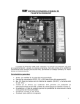
Antes de
de utilizar
utilizar su
su nuevo
nuevo Multímetro
Kit C
Antes
digital con probador
de cables, por favor lea las siguientes recomendaciones.
NUNCA aplique al multímetro, voltaje o corriente que exceda a
las especificaciones máximas de medición.
EXTREME SUS PRECAUCIONES al trabajar con altos voltajes.
NO MIDA voltajes que excedan los 1000V en CD ó 750V en CA
NUNCA conecte los cables de prueba del medidor a una fuente
de voltaje, cuando el selector de funciones está en la escala de;
Corriente, Resistencia o Prueba de diodo. Hacerlo puede dañar
el medidor y será invalida la garantía.
SIEMPRE descargue los capacitores (Uniendo sus 2 terminales,
en especial los electrolíticos) en el caso de los capacitores-filtro
de las fuentes de voltaje tenga mucho cuidado, ya que puede
haber un gran arco de voltaje al descargarse. Desconecte la
energía del circuito a medir antes hacer mediciones y/o pruebas
de Resistencias ó Diodos.
SIEMPRE apague el multímetro cuando no lo ocupe.
ESPAÑOL-02
ESPAÑOL
IMPORTANTE
•
•
•
•
•
Continuidad audible.
Auto apagado.
Retención de datos y Luz.
Probador de cables USB (de A a A, B, mini 5P)
Probador de cables de red o telefónico (RJ45, RJ11, RJ12)
1.- Pantalla digital.
CONTROLES
13
2.- HOLD/TEST
Oprima este botón para retener
los datos mostrados en pantalla.
y para realizar las pruebas de los
cables USB y de RED en modo
manual.
3.- Selector rotatorio.
1
12
2
11
3
4.- 20A
Conector de entrada positivo
para medir Corriente de hasta 20A 4
5.- Conector de entrada
positivo para medir corrientes de
hasta 200mA.
5
10
9
6
8
7
6.- Entrada USB de prueba.
7.- Leds indicadores de prueba de cables USB y RED
8.- Puerto de entrada RJ11, RJ12 ó RJ45
ESPAÑOL-03
ESPAÑOL
CARACTERISTICAS
10.- V, ohms
Conector de entrada positivo para medir voltajes de corriente
continua (máx 1000V) o alterna (máx 750V) y también para
medir resistencias (ohms)
11.- Light
Presione este botón para iluminar la pantalla.
12.- Leds indicadores de prueba de cables USB y RED
ESPECIFICACIONES ELECTRICAS
Voltaje de CD
R an g o
200m V
2V
20V
200V
1000V
R eso lu ció n
P recisió n
0.1m V
0.001V
(+/-)(0,5% de lectura + 1 d ígitos)
0.01V
0.1V
1V
(+/-)(0,8% d e lectura + 2 dígitos)
Protección contra sobrecarga:
Rango de 200mV: 250V CD o CA rms.
rangos de 2V-1000V: 1000V CD o CA rms.
Máx. entrada de voltaje: 1000V CD
Impedancia de entrada de 10 Mohms
ESPAÑOL-04
ESPAÑOL
9.- Conector de entrada común.
R an g o
2V
20V
200V
750V
R eso lu ció n
0.001V
0.01V
0.1V
1V
P recisió n
(+/-)(0,8% de lectura + 3 d ígitos)
(+/-)(1,2% de lectura + 3 d ígitos)
Protección contra sobrecarga:
Rango de 200mV: 250V CD o CA rms.
Rangos de 2V-750V: 700V CD o CA rms.
Máx. entrada de voltaje: 750V AC rms
Impedancia de entrada de 10 Mohms
Rango de frecuencia: 40Hz a 200Hz
Corriente de CD
R an g o
20.00m A
200.0m A
20.00A
R eso lu ció n
0.01m A
0.1m A
0.01A
P recisió n
(+/-)(0,8% de lectura + 1 d ígitos)
(+/-)(1,2% de lectura + 1 d ígitos)
(+/-)(2,0% de lectura + 5 d ígitos)
Protección contra sobrecarga:
Rangos mA: fusible 500mA/250V
Corriente de entrada máxima: Entrada 200mA: 200mA
Entrada 20A: 20A
ESPAÑOL-05
ESPAÑOL
Voltaje de CA
R an g o
200.0m A
20.00A
R eso lu ció n
0.1m A
0.01A
P recisió n
(+/-)(2,0% de lectura + 3 d ígitos)
(+/-)(3% de lectura + 7 dígitos)
Protección contra sobrecarga:
Rangos mA: fusible 500mA/250V
Corriente de entrada máxima: En la entrada 200mA: 200mA
20A: 20A
Rango de frecuencia: 40Hz a 400Hz
Resistencia
R an g o
R eso lu ció n
P recisió n
(+/-)(0,8% de lectura + 3 d ígitos)
(+/-)(1,0% de lectura + 2 d ígitos)
Voltaje de circuito abierto: 0.25V
Protección contra sobrecarga: 250V CD o CA rms
ESPAÑOL-06
ESPAÑOL
Corriente CA
MEDICION DE VOLTAJE DE CD o CA
1.- Conecte la punta de prueba roja al conector marcado como
“V/ohm” y la punta negra al conector “COM”.
2.- Fije el selector giratorio al rango V~ si mide voltaje de
corriente alterna o mueva el selector a V - - - si mide voltaje de
corriente directa.
Antes
de utilizar
nuevoes
Kitdesconocido,
C
Si el voltaje
a sersu
medido
fije el selector
en el rango más alto posible de la escala y reduzca el rango
hasta que la lectura obtenida sea la satisfactoria.
3.- Conecte las puntas de prueba al dispositivo o circuito e inicie
la medición.
4.- Encienda el dispositivo o circuito que va a medir, el valor del
voltaje aparecerá en la pantalla digital así como la polaridad.
Si desea retener el dato oprima el botón “HOLD”
V---
V~
ESPAÑOL-07
ESPAÑOL
INSTRUCCIONES DE OPERACION
2.- Si mide Corriente directa (CD) coloque el selector rotatorio
en la posición de A - - -. Si mide Coriente alterna (CA) coloque
el selector en posición de A~
Antes
de utilizar
su nuevo
Kit C
Si la corriente
a medir
es desconocido,
fije el selector en
el rango más alto posible de la escala y reduzca el rango
hasta que la lectura obtenida sea la satisfactoria.
3.- Abra el circuito a ser medido y conecte las puntas de prueba
en SERIE con la carga en donde la corriente debe ser medida.
4.- Lea el valor de la corriente en la pantalla digital.
Si desea retener el dato oprima el botón “HOLD”
Medición de CD
ESPAÑOL-08
ESPAÑOL
MEDICION DE CORRIENTE CD o CA
1.- Coloque la punta de prueba roja en la posición “mA” y
la punta negra en posición “COM” para mediciones máximas
200mA, para corrientes máximas de 20A coloque la punta roja
en la entrada 20A y la punta negra en posición “COM.
ESPAÑOL
Medición de CA
ESPAÑOL-09
1.- Coloque las puntas: la punta roja en “V/ohms” y la punta
negra a “COM”.
2.- Coloque el selector rotatorio en la posición de Ohms.
3.- Si la resistencia a medir esta conectada a un circuito,
apague este circuito y descargue los capacitores antes de
realizar la medición.
4.- Conecte las puntas de prueba a la resistencia a medir.
5.- Lea el valor de resistencia en la pantalla digital.
Si desea retener el dato oprima el botón “HOLD”
ESPAÑOL-10
ESPAÑOL
MEDICION DE RESISTENCIA
1.- Coloque la punta roja en “V/ohms” y la punta negra en
“COM”
2.- Coloque el selector en la posición de diodo
3.- Conecte la punta de prueba roja al ánodo del diodo a ser
medido y la negra al cátodo.
4.- En caso de que el diodo este en buen funcionamiento en
pantalla se desplegará 0,6V para diodos de silicio y 0,3V para
diodos de germanio. En caso de invertir las puntas de prueba
solo el multimetro marcará 1
ESPAÑOL-11
ESPAÑOL
MEDICION DE DIODOS
1.- Coloque las puntas de prueba: La punta roja en “V/ohms” y
la punta negra en “COM”
2.- Coloque el selector en la posición de )))
3.- Conecte las puntas a los puntos del circuito a ser medido.
Si la resistencia es menor de 50 Ohms el zumbador (buzzer)
sonará.
MEDICION DE CABLES RJ45, RJ11, RJ12 Y USB
1.- Conecte en ambos extremos del multímetro un cable USB o
RJ11 o RJ12 o RJ45.
ESPAÑOL-12
ESPAÑOL
MEDICION DE CONTINUIDAD AUDIBLE
En modo AUTO:
Automáticamente realizará la prueba del cable que conectó. Los
LEDs indicadores de ambos extremos se encenderán
Por ejemplo si conectó un cable USB deberán encenderse uno
a uno los LEDs 1, 2, 3 y 4 de forma automática.
Si conecta un cable RJ45 deberán encenderse los LEDs del 1
al 8.
Para un cable RJ11, enecenderan los LEDs 3 al 6
Para un cable RJ12, enecenderán los LEDs 2 al 7
Modo MANUAL:
Los LEDs indicadores de ambos extremos del multímetro se
encenderán de igual forma que en el caso anterior.
La diferencia es que manualmente tiene que oprimir el botón
“HOLD/TESTER” hasta que enciendan uno a uno los LEDs
indicadores de ambos extremos del multímetro.
ESPAÑOL-13
ESPAÑOL
2.- Puede Girar el selector en posición AUTO o MANUAL
1.- En la parte posterior del multímetro desatornille la tapa del
compartimiento de baterías y haga palanca con el soporte para
retirar la tapa.
ESPAÑOL-14
ESPAÑOL
REEMPLAZO DE BATERIAS Y FUSIBLE
3.- Coloque nuevamente la tapa del compartimiento y atornille.
ESPECIFICACIONES
Alimentación: 9V - - - (Batería de 9V)
Resistencia: 200 a 20Mohms precisión +/- 0,8%
Voltaje cc: 200mV a 1000V precisión +/- 0,5%
Voltaje ca: 2V a 750V precisión +/- 0,8%
Corriente cc: 20mA a 20A +/- 0,5%
Corriente ca: 200mA a 20A +/- 1%
Pantalla de LCD: 3 1/2 digitos, con indicador de polaridad.
Temperatura de operación: 0 a 50°C
Humedad relativa < 75%
Antes de utilizar su nuevo Kit C
El diseño del producto y las especificaciones pueden
cambiar sin previo aviso.
ESPAÑOL-15
ESPAÑOL
2.- Coloque una batería cuadrada de 9V, poniendo atención a la
correcta polaridad.
Producto: Multímetro digital con probador de cables
UTP y USB Modelo: MUL-450
Marca: Steren
PÓLIZA DE GARANTÍA
Esta póliza garantiza el producto por el término de un año en todas sus partes y mano de
obra, contra cualquier defecto de fabricación y funcionamiento, a partir de la fecha de entrega.
CONDICIONES
1.- Para hacer efectiva la garantía, presente ésta póliza y el producto, en donde fue
adquirido o en Electrónica Steren S.A. de C.V.
2.- Electrónica Steren S.A de C.V. se compromete a reparar el producto en caso de estar
defectuoso sin ningún cargo al consumidor. Los gastos de transportación serán cubiertos por
el proveedor.
3.- El tiempo de reparación en ningún caso será mayor a 30 días, contados a partir de la
recepción del producto en cualquiera de los sitios donde pueda hacerse efectiva la
garantía.
4.- El lugar donde puede adquirir partes, componentes, consumibles y accesorios, así
como hacer válida esta garantía es en cualquiera de las direcciones mencionadas
posteriormente.
ESTA PÓLIZA NO SE HARA EFECTIVA EN LOS SIGUIENTES CASOS:
1.- Cuando el producto ha sido utilizado en condiciones distintas a las normales.
2.- Cuando el producto no ha sido operado de acuerdo con el instructivo de uso.
3.- Cuando el producto ha sido alterado o reparado por personal no autorizado por
Electrónica Steren S.A. de C.V.
El consumidor podrá solicitar que se haga efectiva la garantía ante la propia casa
comercial donde adquirió el producto. Si la presente garantía se extraviara, el consumidor
puede recurrir a su proveedor para que le expida otra póliza de garantía, previa
presentación de la nota de compra o factura respectiva.
DATOS DEL DISTRIBUIDOR
Nombre del Distribuidor
Domicilio
En caso de que su producto presente
alguna falla, acuda al centro de
distribución más cercano a su domicilio y en caso de
tener alguna duda o pregunta por favor llame a nuestro
Centro de
Atención a Clientes, en donde con gusto le atender-
Número de serie
emos en todo lo relacionado con su producto Steren.
Fecha de entrega
Centro de Atención a Clientes
01 800 500 9000
ELECTRONICA STEREN S.A. DE C.V.
Camarones 112, Obrero Popular, 02840, México, D.F. RFC: EST850628-K51
STEREN PRODUCTO EMPACADO S.A. DE C.V.
Biólogo MaximIno Martínez No. 3408 Int. 3 y 4, San Salvador Xochimanca, México, D.F. 02870,
RFC: SPE941215H43
ELECTRONICA STEREN DEL CENTRO, S.A. DE C.V.
Rep. del Salvador 20 A y B, Centro, 06000, México. D.F. RFC: ESC9610259N4
ELECTRONICA STEREN DE GUADALAJARA, S.A.
López Cotilla No. 51, Centro, 44100, Guadalajara, Jal. RFC: ESG810511HT6
ELECTRONICA STEREN DE MONTERREY, S.A.
Colón 130 Pte., Centro, 64000, Monterrey, N.L. RFC: ESM830202MF8
ELECTRONICA STEREN DE TIJUANA, S.A. de C.V.
Calle 2a, Juárez 7636, Centro, 22000, Tijuana, B.C.N. RFC: EST980909NU5
Antes de
utilizar
sunew
nuevo
Kitrange
C
Before
using
your
Auto
digital multimeter, please
read the following recommendations.
NEVER apply voltage or current that exceeds the maximum
specifications of measurement of the multimeter.
ENGLISH
IMPORTANT
CAUTION when you are working with high voltages.
DO NOT MEASURE voltages higher than 1000V in DC or 750V in AC
NEVER connect testing cables to a voltage source, when
the switch is in the scale:
Current, or Resistance, Test diode. Doing so may damage
meter
ALWAYS discharge the capacitors before measuring.
ALWAYS place the function switch to Off when you
do not use the multimeter.
ENGLISH-02
FEATURES
Audible Continuity
Auto power off
Data hold.
Backlight
USB cable tester (from A to A, B, mini 5P)
Network or phone cable tester (RJ45, RJ11, RJ12)
ENGLISH
•
•
•
•
•
•
CONTROLS
13
1.- LCD display
2.- HOLD/TEST
Press this button for data hold,
or to test UTP and USB cables
3.- Selector switch
1
12
2
4.- 20A jack
5.- mA
You can measure up to 200mA
of current
11
3
4
5
10
9
7.- LEDs indicator of tester of USB 6
UTP cables.
8
6.- USB input
8.- RJ11, RJ12 and RJ45 input
9.- COM jack
ENGLISH-03
7
11.- Light
Press this button and the screen lights up.
12.- LEDs indicator of tester of USB UTP cables.
ELECTRICAL SPECIFICATIONS
DC Voltage
R an g e
200m V
2V
20V
200V
1000V
R eso lu tio n
Accu racy
0.1m V
0.001V
(+/-)(0,5% o f reading + 1 digits)
0.01V
0.1V
1V
(+/-)(0,8% o f reading + 2 digits)
Overload protection:
200mV range: 250V DC or AC rms.
2V-1000V ranges: 1000V DC or AC rms.
Max. voltage input: 1000V DC
Input impedance: 10 Mohms
ENGLISH-04
ENGLISH
10.- V/ohms
You can measure up to 1000V in DC or 750V in AC. Also you
can measure resistance.
R an g e
2V
20V
200V
750V
R eso lu tio n
0.001V
0.01V
0.1V
1V
Accu racy
(+/-)(0,8% o f reading + 3 digits)
(+/-)(1,2% o f reading + 3 digits)
Overload protection:
200mV ranges: 250V DC or AC rms.
2V-750V ranges: 700V DC or AC rms.
Max. voltage input: 750V AC rms
Input impedance 10 Mohms
Frequency range: 40Hz to 200Hz
DC Current
R an g e
20.00m A
200.0m A
20.00A
R eso lu tio n
0.01m A
0.1m A
0.01A
Accu racy
(+/-)(0,8% o f reading + 1 digits)
(+/-)(1,2% o f reading + 1 digits)
(+/-)(2,0% o f reading + 5 digits)
Overload protection:
mA ranges: 500mA/250V fuse
Max. input current: 200mA jack: 200mA jack 200mA
20A jack: 20A jack 20A
ENGLISH-05
ENGLISH
AC Voltage
R an g e
200.0m A
20.00A
R eso lu tio n
0.1m A
0.01A
Accu racy
(+/-)(2,0% o f reading + 3 digits)
(+/-)(3% o f reading + 7 digits)
Overload protection:
mA ranges: 500mA/250V fuse
Max. input current: 200mA jack: 200mA jack 200mA
20A jack: 20A jack 20A
Frequency range: 40Hz to 400Hz
Resistance
R an g e
R eso lu tio n
Accu racy
(+/-)(0,8% o f reading + 3 digits)
(+/-)(1,0% o f reading + 2 digits)
Open circuit voltage: 0.25V
Overload protection: 250V DC or AC rms
ENGLISH-06
ENGLISH
AC Current
MEASURING DC / AC voltage
1.- Connect the red testing point to the jack signaled “V/ohms”
and the black testing point to the jack signaled “COM”.
2.- Set the dial to the V - - - (VCD) / V~ (VCA) setting
Antes
de utilizar
sube
nuevo
Kit C is unknown, set the dial to
When the
value to
measured
the maximum setting. Reduce level by level until reaching
the desired one.
3.- Connect the testing points to the equipment to be measured.
4.- Turn the equipment to be measured on, the voltage will
appear in the LCD display. The polarity will also appear.
If you want to hold the value, press HOLD button.
V---
ENGLISH-07
V~
ENGLISH
INSTRUCTIONS
1.- When measuring up to 200 mA connect the red testing point
to the jack signaled “mA”, when measuring up to 20A connect the
red testing point to the jack signaled “mA”, in both cases insert
the black testing point to the jack signaled “COM”.
2.- Set the dial to A - - - scale if you measure DC or A~ scale if
you measure AC
Antes
de utilizar
sube
nuevo
Kit C is unknown, set the dial to
When the
value to
measured
the maximum setting. Reduce level by level until reaching
the desired level.
3.- Open the circuit and connect the testing points (in serial) to
the equipment to be measured.
4.- Read the value in the LCD display.
If you want to hold the value, press HOLD button.
MEASURING DC
ENGLISH-08
ENGLISH
MEASURING DC/AC CURRENT
ENGLISH
MEASURING AC
ENGLISH-09
1.- Connect the red testing point to the jack signaled “V Ω”
and the black testing point to the jack signaled “COM”.
2.- Set the dial to Ohms (Ω)
3.- Press the RANGE button and select automatic or manual
4.- If the measured resistance is connected to a circuit, turn it off
and discharge the capacitors before to measure.
5.- Connect the testing points to the resistance to be measured.
6.- The resistance value will appear on the LCD display.
If you want hold the value, press the HOLD button.
ENGLISH-10
ENGLISH
MEASURING RESISTANCE
1.- Connect the red testing point in the jack signaled “V Ω” and
the black testing point in the jack signaled “COM”.
2.- Set the dial to
3.- Connect the red testing point to the anode and the black
testing point to the cathode.
4.- In case that the diode is a good function in display will
appear 0.6V for silice diode and 0.3V for germanium diode if you
change the testing points the meter will appear 1
ENGLISH-11
ENGLISH
MEASURING DIODES
1.- Connect the red testing point in the jack signaled “V Ω”
and the black testing point in the jack signaled “COM”.
2.- Set the dial to the “)))” range.
3.- Connect the testing points on the circuit to be measured. If
the resistance is less than 50Ohm the multimeter will sound.
MEASURING RJ45, RJ11, RJ12 AND USB CABLES
1.- Connect a USB or RJ11 or RJ12 or RJ45 cables in both
connectors of the multimeter as shown.
ENGLISH-12
ENGLISH
MEASURING AUDIBLE CONTINUITY
AUTO mode:
Automatically test the connected cable. The LED indicators light
up on both ends of the multimeter.
For example:
If you connected a USB cable then the LEDs 1, 2, 3 and 4
should light on one by one.
If is a RJ45 cable should light on the LEDs 1 to 8
For RJ11 cable, will light on 3 to 6
For RJ11 cable, will light on 2 to 7
MANUAL mode:
The LED indicators light up on both ends from the multimeter
too.
The difference is that you manually must press the “HOLD /
TEST” until the LEDs light on in both ends from the
multimeter.
ENGLISH-13
ENGLISH
2.- Set the dial to AUTO or MANUAL position
1.- In the multimeter´s back, unscrew the battery compartment
cover, then leverage the support for removing the cover.
2.- Insert a 9V battery, pay attention to polarity.
3.- Place again the cover and screw in.
ENGLISH-14
ENGLISH
BATTERY REPLACEMENT
Input: 9V - - - (one 9V battery)
Resistance: 200 to 20Mohms accuracy +/- 0,8%
DC voltage: 200mV to 1000V accuracy +/- 0,5%
AC voltage: 2V to 750V accuracy +/- 0,8%
DC current: 20mA to 20A +/- 0,5%
AC current: 200mA to 20A +/- 1%
LCD screen: 3 1/2 digits, with polarity indicator.
Operating temperature: 0 to 50°C
Relative Humidity < 75%
Antes
dedesign
utilizarand
su nuevo
Kit C
Product
specifications
are subject to change,
without notice.
ENGLISH-15
ENGLISH
SPECIFICATIONS
Product: Digital multitester with UTP and USB
cable tester
Part number: MUL-450
Brand: Steren
WARRANTY
This Steren product is warranted under normal usage against defects in
workmanship and materials to the original purchaser for one year from the
date of purchase.
CONDITIONS
1.- This warranty card with all the required information, invoice or purchase
ticket, product box or package, and product, must be presented when warranty
service is required.
2.- If the product stills on the warranty time, the company will repair it free of
charge.
3.- The repairing time will not exceed 30 natural days, from the day the claim
was received.
4.- Steren sell parts, components, consumables and accessories to customer,
as well as
warranty service, at any of the addresses mentioned later.
THIS WARRANTY IS VOID IN THE NEXT CASES:
If the product has been damaged by an accident, acts of God, mishandling,
leaky batteries, failure to follow enclosed instructions, improper repair by
unauthorized personnel, improper safe keeping, among others.
a) The consumer can also claim the warranty service in the purchase
establishment.
b) If you lose the warranty card, we can reissue it, if you show the invoice or
purchase ticket.