1
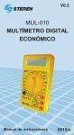
MULTÍMETRO DIGITAL PROFESIONAL
CON PUNTA ILUMINADA
MUL-270
Gracias
por haber adquirido su nuevo Multímetro Digital.
Para apoyo, compras y para todo lo nuevo que
tiene Steren, visite nuestro sitio Web en:
www.steren.com
2
CARACTERÍSTICAS
- Precisión en CD de ± 0,5%.
- Rango completo, ajuste automático a cero, indicador de
polaridad, sobrerango y batería baja.
- Resolución de 0,1µA para pequeñas corrientes.
- Amplio rango de medición en corriente 20A.
- Protección por sobrecarga e indicador audible para mediciones
incorrectas.
Antes de utilizar su nuevo Multímetro Digital Económico con
Prueba de Transistores lea este instructivo para evitar cualquier
mal funcionamiento. Guárdelo para futuras referencias.
3
VOLTÍMETRO DE CD
Impedancia de entrada: 10MΩ para rangos pequeños
Protección de sobrecarga: Para picos mayores a 1000V excepto para
el rango de 200mV con un valor máximo de 250V rms.
Rango
200 mV
2V
20V
200V
1 000V
Resolución
100µV
1mV
10mV
100mV
1V
Precisión
±0,5% ±1 dígitos
VOLTÍMETRO DE CA
Impedancia de entrada: 10MΩ en todos los rangos.
Rango de frecuencia: 40Hz a 400Hz
Protección de sobrecarga: Para picos mayores a 750 rms
Valor promedio (rms de la onda senoidal)
Rango
2V
20V
200V
750V
4
Resolución
1mV
10mV
100mV
1V
Precisión
±0,8% ±3 dígitos
±1,2% ±3 dígitos
AMPERÍMETRO DE CD
Protección de sobrecarga: Fusible de 0,3A/250V (Rango 20A)
Rango máximo de corriente: 20A max. (arriba de 10A sólo por 15s)
Caída de Voltaje: 200mV
Rango
2mA
20mA
200mA
10A
20A
Resolución
1µA
10µA
100µA
10mA
10mA
Precisión
±0,8% ±1 dígito
±1,5% ±1 dígito
±2,0% ±5 dígitos
AMPERÍMETRO DE CA
Protección de sobrecarga: Fusible de 0,3A/250V (Rango 20A)
Rango de frecuencia: 40Hz a 1 000Hz.
Rango máximo de corriente: 20A max. (Arriba de 10A sólo 15s)
Caída de Voltaje: 200mV
Valor promedio (rms de la onda senoidal).
Rango
20 mA
200mA
10A
20A
Resolución
10 µA
100µA
10mA
10mA
Precisión
±1,0% ±3 dígitos
±3% ±7 dígitos
5
OHMETRO
Protección de sobrecarga: 220VCD o CA rms
Voltaje a circuito abierto: -700mV
Humedad: 0-75%, 0-35˚C en 2MΩ y 20MΩ, 0-90% 0-35˚C en
cualquier otro rango
Rango
Resolución
Precisión
200 Ω
0,1Ω
±0,8%±3 dígitos
2kΩ
1Ω
20kΩ
10Ω
±0,8± 1 dígito
200kΩ
100Ω
2MΩ
1kΩ
20MΩ
10kΩ
±1% ±2 dígitos
200MΩ
100kΩ
±5% ±10 dígitos
CAPACITANCIA
Señal de prueba: alrededor de 400Hz 40mV rms
Rango
2 nF
20 nF
200 nF
2 µF
20 µF
6
Resolución
1 pF
10 pF
100 pF
1 nF
10 nF
Precisión
± 4% ± 3 dígitos
FRECUENCIA
Rango: 20kHz
Resolución: 10Hz
Precisión: ± 1,5% ± 5 dígitos
Sensibilidad de entrada: ≤ 100 mV rms máx.
Protección contra sobrecarga: 250V rms
TEMPERATURA
Rango
-20 a 0 °C
0 a 400 °C
400 a 1000 °C
Resolución
1°C
1°C
1°C
Precisión
± 5% ± 3 dígitos
± 1% ± 3 dígitos
± 2% ± 3 dígitos
PROBADOR DE DIODO Y CONTINUIDAD
Rango
Condiciones de
prueba
Corriente pol. dir.
aprox. 1mA CD
Voltaje pol. Inv.
aprox. 2,8VCD
Circuito abierto
Voltaje aprox.
2,8VCD
Precisión
Lectura aproximada
de voltaje de
polarización directa
Audible si la
resistencia
es menor a 70Ω
PROBADOR DE TRANSISTORES
Rango
hFE
Condiciones de
prueba
lb=10μA y
Vce=2,8V
Precisión
Transistores NPN
y PNP con un
rango entre
0-1000
INSTRUCCIONES DE OPERACION
Mediante el encendido del instrumento podemos checar si la
batería se encuentra en buenas condiciones. Si la batería esta baja,
aparecerá en el display “LOBAT” o “BAT”.
El símbolo ! indica que el voltaje o corriente no deben exceder los
valores indicados. Se usa para prevenir daños en los circuitos
internos. Antes de realizar cualquier medición debemos elegir el
rango correcto.
Mediciones de Voltaje de CD y CA
Conectar la punta roja a “V Ω HZ” y la negra a “COM”. Colocar la
perilla de funciones en el rango correcto de voltaje de CD o CA y
realizar la medición. Si aparece en el display la lectura de “1”, quiere
decir que el voltaje que se esta midiendo excede el rango
seleccionado, por lo tanto, debemos elegir uno más alto.
7
Si no sabemos el valor del voltaje a medir, se recomienda usar el
rango mas alto.
Evitar rebasar los limites de medición 1000V de CD y 750V rms
de CA(~). A pesar de que pueden lograrse lecturas mas altas a
los límites, esto provoca daños en el instrumento.
Cuando una de las puntas no se encuentra bien conectada,
podemos tener alguna lecturas especialmente en los rangos de
200mA y 2V, lo cual es normal. La lectura es cero cuando existe
un circuito abierto.
Mediciones de Corriente de CD y CA
- Conectar la punta roja al jack “A” para lectura entre 2A y 20A (20A
max. 10 seg.) y la punta negra al jack “COM”.
- Colocar la perilla en el rango más alto y gradualmente reducir éste,
dependiendo de la lectura medida por el instrumento.
Esta función protegida por un fusible de 2A/250V Poner
especial atención en el rango de 20A ya que este no se
encuentra protegido por ningún fusible. Cuando se usa este
rango la lectura máxima debe ser de 20A pero no por más de
15 s, debido a que si la mantenemos por más tiempo provocara
daños en las resistencias internas del instrumento.
8
Mediciones de Resistencia
A.) Conectar la punta roja a “V Ω Hz” y la negra a “COM”.
B.) Colocar la perilla en la función de Ohmmetro, elegir el rango
correcto y proceder a realizar las mediciones.
- Cuando existe un circuito abierto en el display aparecerá “1”
como en la condición de sobrerango.
- Si la resistencia medida excede el rango seleccionado esto
será condición de sobrerango y leeremos en el display “1”, por
lo tanto, seleccionaremos un rango más alto. Para valores de 1M
o mas el aparato puede tardarse algunos segundos de
estabilizarse. Lo cual es normal.
- Cuando se cheque resistencia en los circuitos, tener cuidado
de que estos se encuentren desenergizados y los capacitores
completamente descargados.
Medición de Capacitancia
Antes de realizar una medición recuerde que le toma tiempo al
medidor ajustarse a cero cada vez que cambiamos de rango.
1. Coloque el capacitor en el conector del medidor, asegúrese que
la polaridad es la correcta (si conecta en forma invertida el signo “-”
aparecerá en la pantalla).
2. Lea el valor del capacitador en la pantalla digital.
9
Medición de Frecuencia
1. Coloque las puntas de prueba: roja en “V Ω Hz” y negra en “COM”
2. Coloque el selector en la posición de kHz
3. Conecte la punta a través del circuito a medir, la lectura aparecerá
en la pantalla.
Medición de Temperatura
Inserte el termopar en el medidor y coloque la punta donde desea
medir la temperatura, la lectura se mostrará en la pantalla.
Probador de Diodos
A. Conectar la punta roja a “V Ω Hz” y la negra a “COM”. La
polaridad de la punta roja será positiva.
B. Seleccionar la función de
y realizar las mediciones.
- Cuando alguna de las puntas no esta conectada
(circuito abierto), en el display aparecerá un “1” como en la
condición de sobrerango.
- Cuando se utiliza esta función, circula por el elemento de
prueba una corriente de 1mA aprox.
El Voltaje en polarización directa esta dado en mV, en
polarización inversa aparecerá en el display un “1”.
10
Probador de Continuidad Audible
A. Conectar la punta roja a “V Ω Hz” y la negra a “COM”.
B. Colocar la perilla en la posición “
”
C. El medidor sonara si la resistencia entre las puntas es igual o
menor a 70Ω.
-Cuando existe circuito abierto aparece en el display “1” como
en la condición de sobrerango.
- Si por error se utiliza esta función cuando el circuito se
encuentra energizado, el medidor sonará para advertir la falla.
Esto no causará ningún daño.
Probador de Transistores
Colocar la perilla selectora en la posición hFE. Determine que tipo de
transistor es y localice el emisor, la base y el colector. El medidor nos
dará la lectura aproximada de hFE a una corriente de base Ib=10µA
y Vce = 2,8V.
PRECAUCIONES PARA LA OPERACIÓN GENERAL
1. Nunca conectar el multímetro a mas de 1000V de CD o 750V rms
de CA
2. Nunca usar un rango inapropiado, ya que esto dañará la
circuitería interna del instrumento.
3. Nunca usar el aparato si la cubierta de la batería no esta en su
lugar y totalmente cerrada.
4. El reemplazo de la batería y el fusible deben hacerse con las puntas desconectadas y el aparato apagado.
CARACTERÍSTICAS
Dimensiones: 190 X 88 X 34mm
Peso: 223g (incluyendo la pila)
Accesorios: Puntas de prueba y pila de 9V
Las características del equipo pueden ser modificadas sin
previo aviso.
11
Producto: Multímetro Digital Profesional con Punta Iluminada
Modelo: MUL-270
Marca: Steren
PÓLIZA DE GARANTÍA
Esta póliza garantiza el producto por el término de un año en todas sus partes y mano de obra, contra cualquier defecto
de fabricación y funcionamiento, a partir de la fecha de entrega.
CONDICIONES
1.- Para hacer efectiva la garantía, presente ésta póliza y el producto, en donde fue adquirido o en Electrónica Steren
S.A. de C.V.
2.- Electrónica Steren S.A de C.V. se compromete a reparar el producto en caso de estar defectuoso sin ningún cargo al
consumidor. Los gastos de transportación serán cubiertos por el proveedor.
3.- El tiempo de reparación en ningún caso será mayor a 30 días, contados a partir de la recepción del producto en
cualquiera de los sitios donde pueda hacerse efectiva la garantía.
4.- El lugar donde puede adquirir partes, componentes, consumibles y accesorios, así como hacer válida esta garantía es
en cualquiera de las direcciones mencionadas posteriormente.
ESTA PÓLIZA NO SE HARA EFECTIVA EN LOS SIGUIENTES CASOS:
1.- Cuando el producto ha sido utilizado en condiciones distintas a las normales.
2.- Cuando el producto no ha sido operado de acuerdo con el instructivo de uso.
3.- Cuando el producto ha sido alterado o reparado por personal no autorizado por Electrónica Steren S.A. de C.V.
El consumidor podrá solicitar que se haga efectiva la garantía ante la propia casa comercial donde adquirió el producto.
Si la presente garantía se extraviara, el consumidor puede recurrir a su proveedor para que le expida otra póliza de
garantía, previa presentación de la nota de compra o factura respectiva.
DATOS DEL DISTRIBUIDOR
ELECTRONICA STEREN S.A. DE C.V.
Camarones 112, Obrero Popular, 02840, México,
D.F. RFC: EST850628-K51
Nombre del Distribuidor
STEREN PRODUCTO EMPACADO S.A. DE C.V.
Biólogo MaximIno Martínez No. 3408 Int. 3 y 4,
Producto
San Salvador Xochimanca, México, D.F. 02870,
RFC: SPE941215H43
ELECTRONICA STEREN DEL CENTRO, S.A.
Modelo
DE C.V.
Rep. del Salvador 20 A y B, Centro, 06000,
Número de serie
México. D.F. RFC: ESC9610259N4
ELECTRONICA STEREN DE GUADALAJARA,
Fecha de entrega
S.A.
López Cotilla No. 51, Centro, 44100, Guadalajara,
Jal. RFC: ESG810511HT6
En caso de que su producto presente alguna falla, acuda al centro de distribución más ELECTRONICA STEREN DE MONTERREY, S.A.
cercano a su domicilio y en caso de tener alguna duda o pregunta por favor llame a
Colón 130 Pte., Centro, 64000, Monterrey, N.L.
nuestro Centro de Atención a Clientes, en donde con gusto le atenderemos en todo lo RFC: ESM830202MF8
relacionado con su producto Steren.
ELECTRONICA STEREN DE TIJUANA, S.A.
de C.V.
Calle 2a, Juárez 7636, Centro, 22000, Tijuana,
Centro de Atención a Clientes
12
B.C.N. RFC: EST980909NU5
01 800 500 9000
ILUMINATED TEST LEAD PROFESSIONAL MULTITESTER
MUL-270
Thank you
for purchasing your new Digital Multitester. For
support, shopping, and everything new at Steren,
visit our website at:
www.steren.com
2
FEATURES
- Accuracy of ± 0,5% in DC
- Full range, automatic set to zero, polarity indicator, over range and
low battery indicator.
- 0,1µA resolution for small currents
- Wide range on 20A current measures
- Protection against over charge and audible indicator for incorrect
measures
Before using your new Digital Multitester, please read this
instruction manual to prevent any damage. Put it away in a safe
place for future references.
3
DC VOLTMETER
Input impedance: 10MΩ for small ranges
Overload protection: for peaks higher than 1 000V, except for 200mV
range with a maximum value of 225V(~) rms.
Range
200 mV
2V
20V
200V
1 000V
Resolution
100µV
1mV
10mV
100mV
1V
Accuracy
±0,5% ±1 digits
AC VOLTMETER
Input impedance: 10MΩ for small ranges
Frequency range: 40Hz to 1 000Hz
Overload protection: for peaks higher than 1 000V, except for 200mV
range with a maximum value of 225V(~) rms.
Average value (rms of the sine wave)
Range
2V
20V
200V
750V
4
Resolution
1mV
10mV
100mV
1V
Accuracy
±0,8% ±3 digits
±1,2% ±3 digits
DC AMPEREMETER
Overload protection: 2A/250V fuse
Maximum current range: 20A max. 15s
Voltage loss: 200mV
Range
2mA
20mA
200mA
10A
20A
Resolution
1µA
10µA
100µA
10mA
10mA
Accuracy
±0,8% ±1 dígit
±1,5% ±1 dígit
±2,0% ±5 dígits
AC AMPEREMETER
Overload protection: 2A/250V fuse
Frequency range: 40 to 1 000Hz
Maximum current range: 20A max. 15s
Average value (rms of the sine wave)
Voltage loss: 200mV
Range
20 mA
200mA
10A
20A
Resolution
10 µA
100µA
10mA
10mA
Accuracy
±1,0% ±3 digits
±3% ±7 digits
5
OHMETER
Overload protection: 220VCD or CA rms
Voltage in an open circuit: -700mV
Humidity: 0 – 75%, 0 –35°C in 2MΩ, 0-90% 0-35˚C in any other range
Range
Resolution
Accuracy
200 Ω
0,1Ω
±0,8%±3 digits
2kΩ
1Ω
20kΩ
10Ω
±0,8± 1 digit
200kΩ
100Ω
2MΩ
1kΩ
20MΩ
10kΩ
±1% ±2 digits
200MΩ
100kΩ
±5% ±10 digits
CAPACITANCE
Proof signal: around 400Hz 40mV rms
Range
2 nF
20 nF
200 nF
2 µF
20 µF
6
Resolution
1 pF
10 pF
100 pF
1 nF
10 nF
Accuracy
± 4% ± 3 dígits
FREQUENCY
Range: 20kHz
Resolution: 10Hz
Accuracy: ± 1,5% ± 5 dígitos
Input sensitivity: ≤ 100 mV rms max.
Overload protection: 250V rms
TEMPERATURE
Range
-20 to 0 °C
0 to 400 °C
400 to 1000 °C
Resolution
1°C
1°C
1°C
Accuracy
± 5% ± 3 dígits
± 1% ± 3 dígits
± 2% ± 3 dígits
DIODE AND CONTINUITY TESTER
Overload protection: 250V DC or AC rms
Range
Test conditions
Direct pol. current
1mA CD approx.
Inverted pol. voltage
2,8VDC approx.
Opened circuit
approx. voltage
2,8VDC
Accuracy
Approx. Direct
polarization voltage
reading
Audible if the
resistance is
under 70ohm
TRANSISTOR TESTER
Range
hFE
Test conditions
lb=10uA y
Vce=2,8V
Accuracy
NPN & PNP
transistors
with a range between
0-1000
INSTRUCTIONS
With this meter we can check the battery status. If one battery have
not enough energy, you will see “LOBAT” or “BAT” in the LCD screen.
The symbol ¡ indicates that the voltage or the current must not
exceed the indicated values. It is used to prevent damages in the
internal circuits. Before to measure, we should choose the correct
range.
Measuring DC / AC voltage
1.- Connect the red testing point to the jack signaled “V Ω Hz” and the
black testing point to the jack signaled “COM”.
2.- Set the dial to the VDC / VAC setting . If you see “1” in the display,
it means the measured voltage exceed the selected range. Please,
select a higher one.
7
Do not introduce DC voltages above 1000 VDC or AC voltage
above 750 VAC. Nevertheless you can obtain readings higher
than the limits, this can damage the meter.
If one of the testing point is not well connected, you can obtain
some readings, specially in 200mA and 2V ranges, which is
normal. When the reading is zero, the circuit is probably opened.
Measuring DC and AC current
1.- Connect the red testing point to the jack signaled ““V Ω Hz”” for
readings between 2A and 20A (maximum 10 seconds with 20A) and
the black testing point to the jack signaled “COM”.
Set the dial to the VDC setting
2.- Set the dial to the maximum setting. Reduce level by level until
reaching the desired level.
This functions it is protected by a 2A/250V fuse. Pay special
attention to 210A range, because this range is not protected by
any fuse. If you use this range, the maximum range of reading
must be 20A, for 15 seconds as maximum,
otherwise it will damage the internal resistances.
Measuring Capacitance
8
Remember that takes time to the multimeter to recover when we
change range.
1. Place the capacitor in the multimeter connector. Take care of
polarity (if it’s wrong the “-“ sign will appear).
2. Read the capacitor’s value.
Measuring Frequency
1. Connect the red testing point to the jack signaled ““V Ω Hz”” and
the black testing point to the jack signaled “COM”.
2. Place the selector on kHz position.
3. Place the points along the circuit you want to measure.
Measuring Temperature
Connect the thermopair to the multimeter and place the point where
you want to measure temperature. It will display on screen.
Testing diodes
1.- Connect the red testing point to the jack signaled ““V Ω Hz”” and
the black testing point to the jack signaled “COM”.
2.- Set the dial to DIODE range and measure the diode.
If one of the testing points is not connected to the circuit, the
LCD screen will display “1”, indicating an over range.
When you use this function, through the testing element circulates a 1mA current, approximately.
The voltage in direct polarization is displayed in mV, in
inverted polarization the LCD screen will display “1”.
9
Measuring audible continuity
1.- Connect the red testing point in the jack signaled ““V Ω Hz”” and
the black testing point in the jack signaled “COM”.
2.- Set the dial to the “
” range.
3.- Connect the testing points on the circuit to be measured. If the
resistance is less than 70 Ω the meter will sound.
If the circuit is open, the LCD screen will display “1”,
indicating over range.
If you use this function while the circuit is energized, the buzzer
will sound to warning you. Don’t worry about it, it won’t cause
any damage.
Transistor measurement –hFE-
1.- Set the dial to the hFE range.
2.- Determine if the transistor is NPN or PNP and localize the emitter,
base, and collector.
3.- The meter will show the approximate hFE value with base current
condition of 10 uA and VCE 2.8 V.
CAUTION
1.- Do not introduce DC voltages above 1000 VDC or AC voltage
above 750 VAC.
2.- Never use an inappropriate range, it would damage the
internal circuits.
3.- Never use your meter if the protective cover is not properly placed.
4.- Before replacing the meter’s battery or fuses, make sure to disconnect the testing points and turn the meter off.
CHARACTERISTICS
Dimensions:190 X 88 X 34mm
Weight: 223 g (battery included)
Accessories: testing points and 9V battery
The characteristics for this multimeter are subject to change
without notice.
10
Product: Digital Multimeter
Part number: MUL-270
Brand: Steren
WARRANTY
This Steren product is warranted under normal usage against defects in workmanship and materials to the original purchaser for one year from the date of purchase.
CONDITIONS
1.- This warranty card with all the required information, invoice or purchase ticket, product box or package, and product,
must be presented when warranty service is required.
2.- If the product stills on the warranty time, the company will repair it free of charge.
3.- The repairing time will not exceed 30 natural days, from the day the claim was received.
4.- Steren sell parts, components, consumables and accessories to customer, as well as warranty service, at any of the
addresses mentioned later.
THIS WARRANTY IS VOID IN THE NEXT CASES:
If the product has been damaged by an accident, acts of God, mishandling, leaky batteries, failure to follow enclosed
instructions, improper repair by unauthorized personnel, improper safe keeping, among others.
a) The consumer can also claim the warranty service in the purchase establishment.
b) If you lose the warranty card, we can reissue it, if you show the invoice or purchase ticket.
11