1
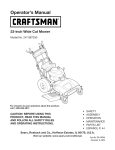
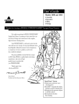
Operator's
Manual
CRRF[SM
®
675 Series
LOG SPLITTER
Model No. 247.77641
o SAFETY
ASSEMBLY
OPERATION
MAINTENANCE
PARTS LIST
Espa_ol
CAUTION: Before using
this product, read this
manual and follow all
safety rules and operating
instructions.
Sears Brands
Management
Visit
Corporation,
our website:
Hoffman
www.craftsman.corn
Estates, iL 60179, U.S.A.
FORMNO. 769-05240A
6/11/2010
WarrantyStatement
..................................
Pace2
SafeOperationPractices
..........................
Paces 3-5
SafetyLabels............................................
Pace6
Assembly
..................................................
Paces 7-10
Operation
..................................................
Paces 11-14
Service&Adjustments
.............................
Paces 15
Maintenance
.............................................
Paces 16-18
OffSeasonStorage..................................
Page19
Troubleshooting
........................................
Page20-21
PartsList...................................................
Page22-30
RepairProtection
Agreement
...................
Page31
Espa_ol
.....................................................
Page35
ServiceNumbers......................................
BackCover
CRAFTSMAN
FULLWARRANTY
Whenoperatedandmaintained
according
toallsuppliedinstructions,
ifthisCraftsman
logsplitterfailsdueto
a defectinmaterialorworkmanship
withinoneyearfromthedateof purchase,
call1-800-4-MY-HOME®
to
arrangeforfreerepair(orreplacement
if repairprovesimpossible).
Thiswarrantyappliesforonly90daysfromthedateof purchaseifthislogsplitteris everusedforcommercial
or rentalpurposes.
This warranty
•
covers ONLY defects in material and workmanship.
Sears will NOT pay for:
Expendable items that become worn during normal use, including but not limited to spark plug, air cleaner,
belts, and oil filter.
Standard maintenance servicing, oil changes, or tune-ups.
Tire replacement or repair caused by punctures from outside objects, such as nails, thorns, stumps, or glass.
Tire or wheel replacement or repair resulting from normal wear, accident, or improper operation or
maintenance.
Repairs necessary because of operator abuse, including but not limited to damage caused by over-speeding
the engine, or from impacting objects that bend the frame, auger shaft, etc.
Repairs necessary because of operator negligence, including but not limited to, electrical and mechanical
damage caused by improper storage, failure to use the proper grade and amount of engine oil, or failure to
maintain the equipment according to the instructions contained in the operator's manual.
Engine (fuel system) cleaning or repairs caused by fuel determined to be contaminated or oxidized (stale). In
general, fuel should be used within 30 days of its purchase date.
Normal deterioration and wear of the exterior finishes, or product label replacement.
This warranty applies only while this product is within the United States.
This warranty gives you specific legal rights, and you may also have other rights which vary from state to state.
Sears, Roebuck and Co., Hoffman Estates, IL 60179
Model Number .............................................................
Serial Number ..............................................................
Date of Purchase ..........................................................
Engine Series: 126L02-0531
Engine Oi1:
SAE 30
Engine Oil Capacity:
20 Ounces
Fuel Capacity:
1.5 Quarts
Spark Plug (.030" Gap): Champion® RJ19LM
Hydraulic Fluid/Capacity: Dexron® III/3.0 gal.
Record the model number, serial number
and date of purchase above
2
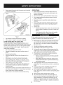
This machinewas built to be operatedaccordingto the safe operation practicesin this manual.As with any type of powerequipment,
carelessnessor error on the part of the operatorcan resultin
seriousinjury.This machineis capableof amputatingfingers,hands,
toes and feet and throwingdebris. Failureto observethe following
safetyinstructionscouldresultin seriousinjuryor death.
which,if not followed,could endangerthe personal
This
symbolpointsout
importantsafetyinstructions
safetyand/or
propertyof
yourselfand others.Read
and followall instructionsin this manualbefore
4_
attemptingto operatethis machine.Failureto comply
with these instructionsmay resultin personalinjury.
Whenyousee this symbol,HEEDITSWARNING!
CALIFORNIA
PROPOSITION
65
Your Responsibility-- Restrictthe use of this powermachine
to personswho read,understandand follow thewarningsand
instructionsin this manualand on the machine.
EngineExhaust,someof its constituents,and certainvehicle
componentscontainor emit chemicalsknownto Stateof California
to cause cancerand birthdefects or other reproductiveharm.
SAVE THESE INSTRUCTIONS!
TRAINING
1.
2.
3.
4.
5.
10. Leakscanbe detectedby passingcardboardor wood, while
wearingprotectiveglovesand safetyglasses,overthe suspected
area. Lookfor discolorationof cardboardor wood.
Read,understand,and followall instructionson the machineand
in themanual(s)beforeattemptingto assembleand operate.
Keepthis manualin a safe placefor futureand regularreference
and for orderingreplacementparts.
Be familiarwith all controlsand their properoperation.Knowhow
to stop the machineand disengagethemquickly.
11. If injuredby escapingfluid, see a doctorimmediately.Serious
infectionor reactioncandevelopif propermedicaltreatmentis not
administeredimmediately.
12. Keeptheoperatorzoneand adjacentarea clearfor safe,secure
footing.
13. If your machineis equippedwith an internalcombustionengine
and is intendedfor usenear anyunimprovedforest, brush,or
grass coveredland,the engineexhaustshouldbe equippedwith
a spark arrestor.Make sureyoucomplywith applicablelocal,
state,and federalcodes.Takeappropriatefirefightingequipment
with you.
Neverallowchildrenunder 16 yearsof age to operatethis
machine.Children16 and overshouldreadand understandthe
instructionsand safe operationpracticesin this manualand on
the machineand be trainedand supervisedby an adult.
Neverallowadultsto operatethis machinewithoutproper
instruction.
Manyaccidentsoccurwhen morethan one personoperatesthe
machine.If a helper is assistingin stackinglogs, neveractivate
the controluntilthe helperis a minimumof 10feet from the
machine.
6.
Keepbystanders,pets,and childrenat least 10feet from the
machinewhile it is in operation.
7.
8.
9.
Neverallowanyoneto ride on this machine.
Nevertransportcargoon this machine.
Hydrauliclog splittersdevelophigh fluidpressuresduringoperation. Fluidescapingthrougha pin hole openingcan penetrate
yourskin and causeblood poisoning,gangrene,or death.Give
attentionto the followinginstructionsat all times:
14. This machineshouldbe usedfor splittingwoodonly, do notuse it
for anyother purpose.
15. Followthe instructionsin the manual(s)providedwith any
attachment(s)for this machine.
PREPARATION
a.
b.
Do notcheckfor leaks with yourhand.
Do notoperatemachinewith frayed,kinked,cracked,or
damagedhoses,fittings,or tubing.
c.
Stopthe engineand relievehydraulicsystempressureby
cyclingthe valvecontrol leverfrom forwardto reverseseveral
timeswhileengineis not running;returningto neutralbefore
repairingor adjustingfittings,hoses,tubing,or other system
components.
Do notadjust the pressuresettingsof the pumpor valve.
d.
3
1.
2.
Alwayswear safetyshoesor heavyboots.
Alwayswear safetyglassesor safetygoggleswhenoperatingthis
machine.
3.
Neverwearjewelryor looseclothingthat might becomeentangled
inmovingor rotatingparts of the machine.
4.
5.
Makesuremachineis on a flat,dry, solid groundbeforeoperating.
Alwaysblockwheelsto preventunintendedmovement,and lock
beamin eitherthe horizontalor verticalposition.
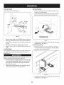
.
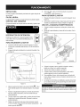
OPERATION
Alwaysoperatethis machinefrom theoperatorzone(s) specified
in the manual.See Figure1.
1.
Vertical
2.
3.
4.
5.
6.
Beforestartingthis machine,reviewthe "SafetyInstructions".
Failureto followthese rulesmay resultin seriousinjuryto the
operatoror bystanders.
Neverleavethis machineunattendedwith the engine running.
Donot operatemachinewhile underthe influenceof alcohol,
drugs, or medication.
Neverallowanyoneto operatethis machinewithoutproper
instruction.
Alwaysoperatethis machinewith all safetyequipmentin place
and working.Makesureall controlsare operatingproperlyfor
safe operation.
OperatorZone
•
•
Figure1
7.
Logsshouldbe cut with squareendsprior to splitting.
8.
Use log splitterin daylightor undergood artificiallight.
SAFE HANDLING
Whenstabilizinglog with left hand,removeyour handwhenthe
wedgejust contactsthe log or seriousinjurymayoccur.
OF GASOLINE
Toavoidpersonalinjuryor propertydamageuseextremecare in
handlinggasoline.Gasolineis extremelyflammableand the vaporsare
explosive.Seriouspersonalinjurycan occurwhengasolineis spilled
on yourselfor yourclotheswhichcan ignite. Washyour skin and
changeclothesimmediately.
•
•
•
•
•
•
•
belowbottomof filler neckto providespacefor fuel expansion.
Replacegasolinecapand tighten securely.
•
•
•
7.
Whenloadinga log, alwaysplaceyourhandson the sideof the
log, noton the ends,and neveruseyour foot to help stabilizea
log. Failureto do so, may resultin crushedor amputatedfingers,
toes, hand,or foot.
8.
Useonly yourrighthand to operatethe controls.
9. Neverattemptto split morethan one log at a time.
10. Forlogswhich are not cut square,the leastsquareend and the
longestportionof the log shouldbe placedtowardthe beamand
wedge,and the squareend placedtowardthe end plate.
11. Whensplittingin the verticalposition,stabilizethe log before
movingthe controlhandle.Splitas follows:
Use onlyan approvedgasolinecontainer.
Extinguishall cigarettes,cigars,pipes,and othersourcesof
ignition.
Neverfuel machineindoors.
Neverremovegas capor add fuel whilethe engineis hot or
running.
Allowengineto coolat leasttwo minutesbeforerefueling.
Neveroverfillthe fueltank. Filltank to no morethan 1/2inch
HorizontalOperatingPosition:Standon thecontrol leverside
of the log splitterand stabilizelog as shown,if needed.See
Figure1.
VerticalOperatingPosition:Standin frontof thelog splitter
and stabilizelog as shown,if needed.See Figure1.
If gasolineis spilled,wipe it off theengineand equipmentand
movemachineto anotherarea.Waitfive (5) minutesbefore
startingtheengine.
Neverstorethe machineor fuel containerinsidewherethereis an
openflame,spark or pilotlightas on a water heater,space heater,
furnace,clothesdryer or othergas appliances.
Allowmachineto cool at least five (5) minutesbeforestoring.
4
•
Placelog on the end plateand turn untilit leansagainstthe
beamand is stable.
•
Whensplittingextra largeor unevenlogs, the log mustbe
stabilizedwith woodenshimsor split woodbetweenthe log
and end plateor ground.
12. Alwayskeepfingers awayfromany cracksthat open in thelog
while splitting.They canquicklyclose and pinchor amputateyour
fingers.
13. Keepyourworkarea clean. Immediatelyremovesplit wood
aroundthe machineso youdo notstumbleover it.
14. Donot changethe enginegovernorsettingsor overspeedthe
engine.The governorcontrolsthe maximumsafe operatingspeed
of the engine.
15. Nevermove this machinewhilethe engineis running.
16. This machineshouldnotbe towedon any street,highwayor
public roadwithoutcheckingtheexistingfederal,state,or local
vehicle requirements.Any licensingor modificationssuch as
taillights,etc., neededto comply,is the sole responsibilityof the
purchaser.If a "Statementof Origin"is requiredin your state,see
your localdealer.
17.Donottowmachine
over45mph.
SPARK ARRESTOR
18.SeeTransporting
theLogSplitter
section
inthismanual
forproper
towing
instructions
once
allfederal,
local,
orstaterequirements
aremet.
This machineis equippedwith an internalcombustionengineand
MAINTENANCE
1.
2.
3.
4.
AND STORAGE
Stopthe engine,disconnectthe spark plugand ground it against
the enginebeforecleaning,or inspectingthe machine.
Stopthe engineand relievehydraulicsystempressureby cycling
the valvecontrolleverfrom forwardto reverseseveraltimeswhile
engineis not running;returningto neutralbeforerepairingor
adjustingfittings,hoses,tubing,or othersystemcomponents.
Topreventfires, cleandebrisand chaff from the engineand
mufflerareas. If the engineis equippedwith a sparkarrester
muffler,cleanand inspectit regularlyaccordingto manufacturers
instructions.Replaceif damaged.
Periodicallycheckthat all nuts and bolts,hoseclamps,and
hydraulicfittingsare tight to be sureequipmentis in safe working
condition.
5.
Checkall safetyguardsand shieldsto be surethey are in the
properposition.Neveroperatewith safety guards,shields,or
otherprotectivefeaturesremoved.
6.
Thepressurereliefvalveis presetat thefactory.Donot adjustthe
valve.
7.
Neverattemptto movethis machineoverhillyor uneventerrain
withouta tow vehicleor adequatehelp.
8.
Foryour safety,replaceall damagedor wornparts immediately
with originalequipmentmanufacturer's(O.E.M) parts only.Use of
parts whichdo notmeet the originalequipmentspecificationsmay
lead to improperperformanceand compromisesafety!
Do notalter this machinein any manner,alterationssuch as
attachinga rope or extensionto the controlhandle,or addingto
the widthor heightof the wedgemay resultin personalinjury.
9.
10. Accordingto the ConsumerProductsSafetyCommission(CPSC)
and the U.S.EnvironmentalProtectionAgency(EPA),this product
hasan Average UsefulLifeof seven(7) years,or 130hoursof
operation.At the end of the Average UsefulLifehavethe machine
inspectedannuallybyan authorizedservicedealer to ensurethat
all mechanicaland safetysystemsare workingproperlyand not
wornexcessively.Failureto do so can resultin accidents,injuries
or death.
shouldnotbe usedon or near anyunimprovedforest-covered,brush
coveredor grass-coveredland unlesstheengine'sexhaustsystem
is equippedwith a sparkarrestermeetingapplicablelocalor state
laws (if any).
If a sparkarresteris used, it shouldbe maintainedin effectiveworking
order by theoperator.Inthe State of Californiathe aboveis required
bylaw (Section4442 of the CaliforniaPublicResourcesCode). Other
statesmayhavesimilarlaws. Federallawsapplyon federallands.
A spark arresterfor the muffleris availablethroughyournearest
engineauthorizedservicedealeror contactthe servicedepartment,
RO. Box361131Cleveland,Ohio44136-0019.
SAFETY
SYMBOLS
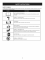
This pagedepictsand describessafetysymbolsthat mayappear on this product. Read,understand,and followall instructionson the machine
beforeattemptingto assembleand operate.
i
i
READTHEOPERATOR'SMANUAL(S)
Read,understand,andfollow all instructionsin the manual(s)beforeattemptingto assemble
and operate
WARNING-- CRUSHINGHAZARD
'l I
Keephandsaway fromwedge,end plate, partiallysplitwood and movingparts.
BYSTANDARDS
Keepbystanders,helpersand childrenat least 10feet away.
SINGLEOPERATOR
Onlyone personshouldoperatethe machineat a time.The adultwho loadsand stabilizesthe
log mustbe the personwho operatescontrol handle.
WARNING-- PRESSURIZEDFLUID
Nevercheckfor hoseleaks with yourhands.High pressurefluidcan escapethrougha pin hole
leakand causeseriousinjuryby puncturingthe skin and causingbloodpoisoning.
EYE PROTECTION
Alwayswear safetyglassesor safetygoggleswhenoperatingthis machine.
WARNING-- MOVINGWEDGE
Keephandsaway fromwedgeand movingparts.
6
8.
Useextremecautionunpackingthis machine.Somecomponentsare
very heavyand will requireadditionalpeopleor mechanicalhandling
equipment.
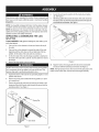
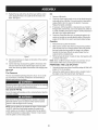
9.
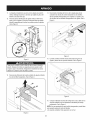
Securethejack standin positionwith theclevis pin and spring
clip. See Figure1.
Withthelogsplitterstillsecuredtothebottomd thecrate,removetwo
hexboltsandhexnutsfromthetankbracketandremovethepieced
woodinsidethetankbrackets.SeeFigure2.
NOTE:Yourlog splitteris shippedwith motoroil in the engine.However,
youMUSTcheckthe oil levelbeforeoperating.Be carefulnot tooverfill.
NOTE:All referencesin this manualto the left or right sideof the log
splitterare from theoperatingpositiononly.See OperatorZonein the
Operationsectionof the Safetyinstructions.
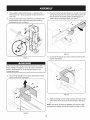
UNPACKING
SPLITTER
& ASSEMBLING
THE LOG
TOOLS NEEDED: Safetyglasses,leathergloves,wirecutters,prybar
and/orclawhammer.
1.
Use a pry bar or claw hammerto loosenand removethe topof
thecrate.
2.
Use a pry bar or claw hammerto removethe sidesof thecrate,
beginningwith the short sides (or left and rightsideof the log
splitter).Setthe sides of the crateasideto avoid injury.
3.
On the front sideof the crate thetongueassemblyis attachedon
the insideof thecrate with a cabletie. Cut the cabletie to remove
4.
thetongue.
Removethe largeplasticcoverand discard.
Figure2
10. Align the holesin the tonguewith the holesin the tank bracket
and securewith the hardwarejust removed.See Figure2.
NOTE: Thehigh pressurehose,which runsfromthe gear pumpto the
bottomof the controlvalve,mustbe abovethetongueassembly.
Do NOTremoveanywoodor cut any strapssecuringthe log splitter
[ or its componentsto the log splitteror thecrate at this time. Only
[ removestrapsand/orwoodwhen instructedto do so.
5.
inspectthe bottomof the crate for anyprotrudingstaplesor wood
splintersand remove.
6.
Removeany looseparts includedwith the log splitter(i.e. operatot's manual,etc.).
Removethe springclip and clevispin from thejack standon the
tongueand then pivotthe jack stand towardsthe groundintothe
operatingposition.See Figure1.
7.
SpringClip
ClevisPin
Jack Stand
Figure1
7
14. Disconnectthe log cradlefromthe beamon theside of the control
valve by removingthe two hexwasherscrewsthat secureit to the
beamand the two hex washerscrewsin the beamflange.The
cradleis off-set for shippingpurposes.See Figure5.
11, Thelog splitteris shippedwith the beamin a verticalposition,
Removeanybolts or strapssecuringthe end plateto the bottom
of the crate.
12. Pull outthe verticalbeamlock, rotateit back,and pivot the beam
to the horizontalpositionuntilit locksbeingsureto avoidany
possiblepinchpoints,See Figure3,
Figure5
15. Lift and slidethe cylinderup to the top of beamand intothe weld
brackets.See Figure6.
Figure3
Takeextra carewhen raisingand loweringthe beamas it is fairly
heavy.Havinga secondpersonassist with raisingor loweringthe
beamis recommended.Be sureto keephandsawayfrom any
possiblepinchpoints.
13. Disconnectthe dislodgerfrom the beamweld bracketby removing the six hex screws.See Figure4.
f
-,
Figure6
16. Attachthe dislodgeroverthe wedgeassemblyand secureit to the
weld bracketswith the previouslyremovedhardware.See Figure
4.
NOTE:Oncethe six hex screwsare tightened,theremay be a slight
gap betweenthe dislodgerand theweld brackets.This gap is normal.
\
Figure4
8
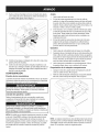
17. Reattachthe log cradleto the sideof the beamwith the control
valve,aligningthe holesin thecradlewith the the holesin the
beam.See Figure7.
Oil
1.
Removeoil fill dipstick.
2.
Checkthe oil levelmakingcertain notto rub the dipstickalongthe
insidewalls of the oil fill tube. This wouldresultin a falsedipstick
reading.Refillto the FULLmark on the dipstick,if necessary.
Replacethe dipstickand tighten.
If necessary,with the log splitteron levelground,use a funnelto
fill enginewith oil to the FULLmark on the dipstick.Be carefulnot
to overfill.Overfillingwillcause the engineto smokeprofuselyand
will resultin poor engineperformance.
....
fJ
3.
4.
Checkthe oil levelthreetimes priorto startingthe engineto be
certain you'vegotten an accuratedipstick reading.Runningthe
enginewith too little oil can resultin permanentengine damage.
Gasoline
1.
2.
Removethe fuelcap from the fueltank.
Makesurethe containerfrom whichyou will pourthe gasolineis
cleanand free from rust or foreignparticles.Neverusegasoline
that maybe stalefrom long periodsof storagein its container.
Gasolinethat has been sittingforany periodlongerthan four
weeksshouldbe consideredstale.
3.
Fillthe fueltank with about 1.5quarts of clean, freshgasolinewith
a minimumof 85 octane.
J
Figure7
18. Checkfor and removeany stapleson the bottomof the cratethat
may puncturethe tire.
NOTE: Neveroverfillthe fueltank. Filltank to no morethan 1/2inch
belowbottomof fillerneck to providespacefor fuelexpansion.
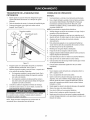
PREPARING THE LOG SPLITTER
19. Cut the metalstrap securingthe log splitterto the bottomof the
crateand removethe woodunderthe engineand/orany other
wood,then roll the log splitteroff the bottomof the shippingcrate.
1.
Lubricatethe beamarea (wherethe splittingwedgewillslide) with
engineoil. Donot usegrease.
2.
Removethe ventedreservoirdipstick,whichis locatedin front of
the engineon topof the reservoirtank.See Figure8.
SET-UP
Tire Pressure
The max recommendedoperatingpressureis 30 psi. Do not, under
anycircumstances,exceedthe manufacturer'srecommendedpsi.
Maintainequal pressureon all tires.
Excessivepressurewhen seatingbeadsmay causetire/rim
to burstwith force sufficientto cause seriousinjury.
Gas and Oil Fill-Up
Servicethe enginewith gasolineand oil as instructedbelow.Readthe
instructionscardully.
Useextremecarewhenhandlinggasoline.Gasolineis extremely
flammableand the vaporsare explosive.Neverfuelthe machine
indoorsor whilethe engineis hot or running.
\
NOTE:Your log splittermaybe shippedwith motoroil in the engine.
You MUSTchecktheoil levelbeforeoperating.Be carefulnot to
overfill.Gasolinecan be addedto theenginewhenthe log splitteris
in eitherthe horizontalor verticalposition.However,it maybe easier
whenthe splitteris in the verticalposition.
jj
\
Figure8
9
\
NOTE:Thelogsplitterisfilledto theproperoperatinglevelfromthemanufacturerwithShellTellus®32 HydraulicFluid.However,
youMUSTcheckthe
fluidlevelbeforeoperating.If notfilled,proceedwiththefollowingsteps:
Muchd the originalfluid hasbeen drawnintothe cylinderand hoses.
Makecertainto refillthe reservoirto preventdamageto the hydraulic
pump.
3.
Checkthefluid levelusingthedipstick.See Figure8. Do not
overfill.
4.
Replacetheventeddipsticksecurely,tighteningit untilthe topof
the threadsare flush with top of the pipe.
Disconnectthe spark plugand primethe pumpby pullingthe
recoilstarteras faras it will go. Repeatapproximately10 times.
5.
6.
7.
Reconnectthe sparkplug wireand start the enginefollowingthe
instructionsin the Operationsection.
Use thecontrol handleto engagethewedgeto the farthest
extendedposition.Then retractthe wedge.
8. Refillthe tank as specifiedon thedipstick.
NOTE: Failureto refillthe tank willvoid the splitter'swarranty.
9. Extendand retractthewedge 12completecyclesto removeany
air trappedin the system(thesystemis "self-bleeding").
10. Refillthe reservoirwithinthe rangemarkedon the dipstick.
NOTE:Somefluid mayoverflowfrom the vent plugas the system
buildsheatand the fluidexpandsand seeksa balancedlevel.
10
Cylinder
ControlHandle
;lodger
Horizontal
BeamLock
CouI
Hitch
BeamAssembly
Plate
Tongue
Engi
Starter Handle
Vertical
Tray
Beam
Reservoir
Lock
Tank
Fi, ure 9
Be familiarwith all the controlsand their properoperation.Knowhow
to stop the machineand disengagethemquickly.
Readthis operator'smanualand the safetyrulesbeforeoperating
yourlog splitter.Comparethe illustrationsbelowwith yourequipment
to familiarizeyourselfwith the locationof variouscontrolsand adjustments.Savethis manualfor future reference.
Alwayswear safetyglasseswhenoperatingthis equipmentor while
performinganyadjustmentsor repairson it.
BEAM
LOCKS
CONTROL
Thesetwo locksare usedto securethe beamin the horizontalor
theverticalposition.The verticalbeamlock is locatedon the tanks
bracket.The horizontalbeamlock is locatedon the beamsupportlatch
bracket.
WEDGE
HITCH
ANSI SAFETY
LOG DISLODGER
STARTER
Thecouplerhitch is at theend of the tongueand attachesto a a tow
ball for transportationpurposes.
MEETS
The controlhandleis usedto movethewedgeup and downto split
wood. Thecontrolhandlehas threepositions;Forward,Neutraland
Reverse.See the "Usingthe LogSplitter"sectionfor instructions.
The log dislodgeris designedto removeany partiallysplitwoodfrom
the wedge.This mayoccur whilesplittinglargediameterwoodor
freshlycut wood.
Thewedgeis usedto splitthe wood.
COUPLER
HANDLE
HANDLE
Usedto startthe engine.
STANDARDS
CraftsmanLogSplittersconformto the safetystandardof the AmericanNationalStandardsInstitute(ANSI).
11
LOG TRAY
8.
Thelog tray is designedto catchthe log after it is split,
If enginefalters, movechoke controlbackto the CHOKEt'°,1
positionand repeatsteps4 through7.
END PLATE
TO STOP ENGINE
Theend plateholdsthelog in placewhilethe wedgesplitsthe log.
1.
2.
TONGUE
Thetongueis usedto attachto a towingvehiclefor transportation.
CHOKE
Pushthe stop switchto the OFF position.See Figure10.
Disconnectspark plugwireand ground it to preventaccidental
startingwhilethe equipmentis unattended.
USING THE LOG SPLITTER
CONTROL
Thechokecontrol is usedto chokethe carburetorand assist in starting
the encinc.
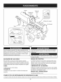
1,
2,
Placethe log splitteron flat, dry, solidground,
Blockthe front and backof bothwheels.See Figure11.
Vertical
STOP SWITCH
Thestop switch is usedto turnoff the engineand must
be pushedbackto the ON positionbeforethe enginewill
start.
TO START
ENGINE
1.
2.
Attachsparkplug wireand rubberbootto spark plug.
Gastank shouldbe filled 3/4 to full beforestarting.
3.
Pushthe stop switchto the ONposition.See Figure10.
f
Horizontal
Figure11
3.
4.
Choke Controli
Figure10
5.
6.
7.
5.
Placethe log againstthe end plateand only split woodalongthe
grain (lengthwise).
6.
To stabilizethelog, placeyourleft handon the sideof the log.
Neverplacea hand betweenthe log and thesplittingwedgeor
the log and end plate.
Onlyone operatoris permitted.Theadultwho loadsand stabilizes
the log mustbe the personwhooperatesthecontrol handle.
Stop Switch
4.
Placethe beamin either thehorizontalor verticalpositionand
lock it intoplace.
Blockthe front and backof bothwheels.
lxl pos t(A
on.
warm
Movethe chokeleverto the CHOKE
enginemay not requirechoking.)See Figure10.
Standingon the left sideof the log splitterand facingthe front of
the engine,graspthe starterhandleand pull the ropeout until you
feela drag.
Pull the ropewith a rapid,continuous,full armstroke.Keepa firm
grip on the starterhandle.Letthe rope rewindslowly.
Repeat,if necessary,untilenginestarts.Whenenginestarts,
movechokecontrolgraduallyto the RUN'_{ I position.
12
Control
Handle
Vertical
Referto Figure12 forthe followingsteps.
Position
1.
Pullthe horizontalbeamlock out to releasethe beamand pivot
the beamto the verticalposition.
2.
To lock thebeamin the verticalposition,pull out on the vertical
beamlock and rotateit to securethe beam.See Figure13.
f
To Return
Wedge
_ToStop
_
Wedge
To Split
Wood
......................................................................................................
:J.........................................
Figure12
1.
Movethe controlhandleto the FORWARDpositionto splitwood.
2.
Removeyour left hand fromthe sideof the log oncewedgejust
contactsthe log. Continuemovingcontrol handleforwardto split
thewood.
3.
Releasethe controlhandleto stopthe wedgemovement.
4.
Movethe controlhandleto the REVERSEpositionto returnthe
wedge.
Figure13
3.
Standin front of the log splitterto operatethe controlhandleand
to stabilizethe log. See Figure11.
Horizontal Position
Pullthe verticalbeamlock out and rotateitdown. See Figure
14.Pivotthe beamto the horizontalposition.The beamwill lock
automaticallyinthe horizontalposition.
Log Dislodger
The log dislodgeris designedto removeanypartiallysplit woodfrom
thewedge.This may occur whilesplittinglarge diameterwoodor
freshlycut wood.
Neverremovepartiallysplit woodfrom the wedgewith your hands.
Fingersmaybecometrappedbetweenthe split wood.
1.
2.
Tofreethe wedgefroma partiallysplit pieceof wood,placethe
controlhandlein the REVERSEposition.As it movesback,the
split woodportionwillcontactthe log dislodgerand become
detachedfrom the wedge.
Onceremovedfrom the wedgewith the log dislodger,splitthe
woodfrom theoppositeend or inanotherlocation.
HorizontalBeamLock
Figure14
.
13
Standbehindthe reservoirtank to operatethe controlhandleand
to stabilizethe log. See Figure11.
TRANSPORTING
THE LOG SPLITTER
1.
Lowerthe beamto itshorizontalposition.Makecertainthe beam
islockedsecurelywith the horizontalbeamlock.
2.
3.
Removespringclip and clevispin from jackstand.
Supportthe tongueand pivotthe jackstand up againstthe
tongue.See Figure15.
OPERATING
TiPS
Always:
8.
9.
f
CouplerHitch
Usecleanfluid and checkthefluid levelregularly.
Usean approvedhydraulicfluid. ApprovedfluidsincludeShell
Tellus®32 HydraulicFluid,Dexron®III/ Mercon®automatic
transmissionfluid, Pro-SelectTM AW-32HydraulicOil or 12WAWISOviscositygrade 32 hydraulicoil.
NOTE:It is not recommendedthat hydraulicfluids be mixed.
10. Alwaysensurethat the filter is in place.Cleanor replacethe filter
regularly.
Spritg Clip
11. This unit comeswitha breathercap on the fluid reservoir.Do not
useanyothertype of reservoircap.
12. Makesurethe pumpis mountedand alignedproperly.
Adjustment
Nut
13. This unit comeswitha flexible"spider"type couplingbetween
the engineand pumpdriveshafts. Donot useany othertype of
coupling.
14. Keepthe hosesclearand unblocked.
15. Bleedthe air out of the hosesbeforeoperating.
ClevisPin
16. Flushand cleanthehydraulicsystembeforerestartingafterservicing.
17. Use"pipedope"on all hydraulicfittings.
18. Allowtime for the engineto warm-upbeforesplittingwood.
19. Primethe pumpbeforethe initial start-upby turningoverthe
enginewith sparkplug disconnected.
JackStand
Figure15
4.
5.
6.
7.
20. Splitthewood alongthe grain (lengthwise)only.
Never:
Securethejack with the springclipand clevispin previously
removed.See Figure15.
1.
Usewhenfluid is below200F or above 1500R
Attachthecouplerhitch to a classI or higher2" ball on a towing
vehicle.Latch securely.
a. If thecouplerhitch doesnot fit on the ball:Turnthe
adjustmentnutlocatedunder thecouplerhitchone turn
counter-clockwise.
2.
Usea solidengine/pump coupling.
3.
b.
4.
Operatethroughreliefvalvefor morethan5 seconds.If the
wedgestopsmovingor reachesthe end of its stroke,releasethe
controlvalve or REVERSEit within5 secondsto avoidputting
stresson the hydraulicsystemand engine.
Attemptto adjust unloadingor reliefvalve settings.
5.
6.
7.
Operatewith air in the hydraulicsystem.
Useteflontape on the hydraulicfittings.
Attemptto cut woodacrossthe grain.
8.
Attemptto removepartiallysplit woodfromthe wedgewith your
hands.Fullyretractthewedgeto dislodgethe woodwith the log
dislodger.
If thecouplerhitch is too looseon the ball: Turnthe adjustment nutlocatedunder thecouplerhitchone turn clockwise.
Connectthe safetychainsto the towingvehicle.
Plug in the tail lights,if so equipped,to the tail lightconnectoron
the towvehicle.
Do nottow fasterthan45 mphand checklocal, state,and federal
requirementsbeforetowingon any publicroad.
NOTE: Usecautionwhenbackingup. Usinga spotteroutsideof the
vehicleis recommended.
14
FLEXIBLE
PUMP COUPLER
Do notat any time makeanyadjustmentswithoutfirststopping
theengine,disconnectingspark plugwire and groundingit against
theengine.Alwayswearsafetyglassesduringoperationor while
_performng anyadjustmentsor repars.
Theflexiblepumpcoupleris a nylon"spider"insert,locatedbetween
the pumpand theengine shaft.Overtime,the couplerwill hardenand
deteriorate.If you detectvibrationor noisecomingfromthe area betweenthe engineand the pumpcontactan authorizedservicedealer.
If thecouplerfails completely,you will experiencea loss of power.
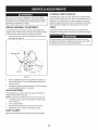
WEDGE
TIRES
ASSEMBLY
ADJUSTMENT
The maximumpressurefor thetires is 30 psi. Do not exceedthe
manufacturer'srecommendedpsi underanycircumstances.Maintain
equal pressureon all tires.
As normalwearoccursand thereis excessive"play"betweenthe
wedgeand beam,adjustthe bolts on the sideof the wedgeassembly
to eliminateexcessspacebetweenthe wedgeand the beam.
1. Loosenthejam nutson the two adjustmentboltson the sideof
thewedge.See Figure16.
Excessivepressurewhen seatingbeadsmay causethe tire/rim
assemblyto burst with forcesufficientto causeseriousinjury.Refer
to sidewallof the tire for the recommendedpressure.
AdjustmentBolt
Gib
Jam Nut
' Lock Nut
Figure16
2.
Turnthe adjustmentbolts in until snugand thenback them off
slowly(approximately1.5turns) untilthe wedgeassemblywill
slideon the beam.
3.
Re-tightenthe jam nuts securelyagainst theside of the wedgeto
securethe adjustmentboltsin this position.
GIB ADJUSTMENT
Periodicallyremoveand replacethe"gibs"(spacers)betweenthe
wedgeassemblyand the back plate.
NOTE:The gibsmay be rotatedand/or turnedoverfor evenwear.
1. Loosenthe lock nuts undereach back plateand slidethegibs
out. See Figure16.
2.
3.
Turnor replacethe gibs.
Reassemblethe back plateand securewith the lock nuts.
4.
Readjustthebolts on the sideof the wedgeassembly.
HOSE CLAMPS
Beforeeach usecheckall the hoseclampsto see if they are tight.
15
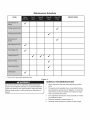
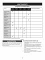
Maintenance
Schedule
TASKS
SERVICEDATES
* -- Heavyloador high ambienttemperatureuse.
Figure 17
GENERAL
Do notat any time makeanyadjustmentswithoutstoppingthe
engine,disconnectingthe spark plugwire, groundingit againstthe
engineand relievethe hydrosystempressure.Alwayswear safety
glassesduringoperationor whileperforminganyadjustmentsor
repairs.
RECOMMENDATIONS
1.
Alwaysobservethe safety ruleswhenperformingany maintenance.
2.
The warrantyon this log splitterdoesnotcover itemsthat have
been subjectedto operatorabuseor negligence.Toreceivefull
valuefrom the warranty,the operatormust maintainthe equipment as instructedin this manual.
3.
4.
Someadjustmentswill needto be madeperiodicallyto maintain
yourequipmentproperly.
Followthe maintenanceschedule(Figure 17).
5.
Periodicallycheckall fastenersand makesurethey are tight.
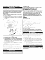
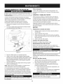
HYDRAULIC
FLUID AND iNLET FILTER
Hydraulic
Filter
Changethehydraulicfilter every 50 hoursof operation.Useonlya 10
micronhydraulicfilter.Order partnumber723-0405.
Stopthe engineand relievehydraulicsystem )ressurebeforechanging or adjustingfittings,hoses,tubing,or othersystemcomponents.
BEAM
AND
SPLITTING
WEDGE
Checkthehydraulicfluid levelin the log splitterreservoirtank before
eachuse. Maintainthe fluid levelwithinthe rangespecifiedon the
dipstickat all times.
Beforeeachuse, lubricateboth sidesof the beam(whereit comesinto
contactwith the splittingwedge)with engineoil. The wedgeplateon
the log splitteris designedsothe gibs on the sideof thewedgeplate
can be removedand rotatedand/or turnedoverfor evenwear.
Changethe hydraulicfluid in the reservoirevery 100 hoursof operation. Followthe stepsbelow:
1. Disconnectthe suctionhosefromthe bottomof the reservoirtank.
Makecertainto readjusttheadjustmentbolts so the wedgemoves
freely,butno excessspaceexistsbetweenthe wedgeplateand the
beam.
2.
ENGINE
Carefullyunthreadthe inletfilter and clean it with penetratingoil.
See Figure18.
f
-,
J,
.......
I
i
................................................
/
/
/
Check Engine
1.
Stoptheengineand wait severalminutesbeforecheckingtheoil
level.
2.
3.
Removethe oil fill dipstick.
Checkthe oil levelon the dipstick.With the engineon level
ground,theoil mustbe to the FULLmarkon thedipstick.
4.
Replacethe dipstickand tighten.
Changing
p
Oil
Engine Oil
Referto an authorizedSearsServiceCenter.
Service
Air Filter
The air filter preventsdamagingdirt, dust, etc.,from enteringthe
carburetorand being forcedintothe engineand is importantto engine
lifeand performance.
\
\
\
\
Neverrunthe enginewithoutan air cleanercompletelyassembled.
,,J
Figure18
3.
Allowthefluid to drain intoa suitablecontainer.
4.
Reinsertthe filter and refillthe reservoir.Approvedfluidsinclude
Shell Tellus®32 HydraulicFluid,Dexron®III / Merconautomatic
transmissionfluid, Pro-SelectTM AW-32HydraulicOil or 10WAWISOviscositygrade32 hydraulicoil.
5.
Maintainthe fluid levelwithinthe rangespecifiedon the dipstick
at all times.
NOTE:Alwaysdisposeof usedhydraulicfluidand engineoil at
approvedrecyclingcentersonly.
Contaminantsin fluidmay damagethe hydrauliccomponents.Flushing
the reservoirtank and hoseswith kerosenewheneverserviceis
performedon the tank, hydraulicpumpor valve is recommended.Any
repairto the hydrauliccomponentsshouldbe performedby a Sears
ServiceCenter.
Use extremecautionwhen workingwith kerosene.It is an extremely
flammablefluid.
Servicethecartridgeevery 25 operatinghoursor every season.
Servicethecartridgemoreoften underdusty conditions.
To Service Air Filter
.
2.
Loosentheair filter coverscrew,butdo not removethe screw
from the cover.Swingthecover downto removefrom the hinge.
Inspectthe filter for discolorationor dirt accumulation.If either is
present,proceedas follows:
a. Cleanthe insideof compartmentand coverthoroughlyand
removethe cartridge.
b. Reassemblethenew cartridgein the compartment.Swing
the coverdownand tightenthe screwloosenedearlier.
Temperatureof mufflerand nearbyareasmay exceed150° F(65°C).
Avoidtheseareas.
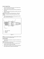
Service
Spark Plug
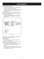
1.
Cleanthe sparkplug and resetthe gap to .030"at leastonce a
seasonor every 50 hoursof operation.
2.
Cleanthearea aroundthe sparkplug. Removeand inspectthe
spark plug.
Replacethe spark plug if the electrodesare pitted,burnedor the
porcelainis cracked.
3.
NOTE:Contacta SearsPartsand RepairCenteror 1-800-4-MYHOME®for a replacementsparkplug,Champion®partnumber
RJ19LM.
4.
Checkthe electrodegap with a wirefeelergaugeand resetthe
gap to .030inches.See Figure19.
3
2
\
r!
mm
ii
114F---___
1
1.
2.
3.
.030(.76 ram) Gap
Electrodes
Porcelain
Figure19
NOTE: Donot sandthe sparkplug.The spark plugshouldbe cleaned
with a wirebrushand a commercialsolvent.
Clean
1.
Engine
Cleantheengine periodically,by removingdirt and debriswith a
cloth or brush.
NOTE: Cleaningwith a forcefulsprayof wateris not recommendedas
watercouldcontaminatethe fuel system.
2.
3.
Toensuresmoothoperationof theengine,keepthe governor
linkage,springsand controlsfreeof debris.
Every 100hoursof operation,removecombustiondepositsfrom
topof cylinder,head,top of pistonand aroundvalves.
Prepare
yourlogsplitter
forstorage
attheendoftheseason
orifthe
logsplitter
willnotbeused
for30daysormore.
FUEL STABILIZER
NOTE: Fuelstabilizeris an acceptablealternativein minimizingthe
formationof fuel gumdepositsduring storage.
Pleasefollowthe instructionsbelowfor storingyourlog splitterwith
Never
store
themachine
withfuelinthefueltankinside
ofbuilding fuel and stabilizerin the engine:
where
fumes
mayreach
anopenflame
orspark
orwhere
ignition
1. Add stabilizerto the gasolinein the fueltank or storagecontainer.
sources
arepresent
suchashotwater
andspace
heaters,
furnaces,
Alwaysfollow the mix ratiofoundon the stabilizercontainer.
clothes
dyers,
stoves,
electric
motors,
etc.
2. Runtheengine at least 10 minutesafteradding stabilizerto allow
the stabilizerto reachthe carburetor.
NOTE:
Ayearly
check-up
byyourlocalSears
service
center
isagood
waytoensure
yourlogsplitter
willprovide
themaximum
performanceNOTE: Do notdrain the gastank and carburetorif usingfuelstabilizer.
nextseason.
Drainall the oil from the crankcase(this shouldbe done afterthe
LOG SPLITTER
engine hasbeen operatedand is still warm)and refillthecrankcase
with fresh oil.
1.
2.
OTHER
Cleanthe log splitterthoroughly.
Wipethe log splitterwith an oiled rag to preventrust,especially
on the wedgeand the beam.
ENGINE
NOTE: It is importantto preventgumdepositsfrom formingin the
essentialfuel systemparts suchas the carburetor,fuelfilter,fuel hose
or tank during storage.Also, alcoholblendedfuels (calledgasoholor
usingethanolor methanol)can attractmoisturewhich leadsto separationand formationof acids during storage.Acidic gascan damagethe
fuel systemof an enginewhile in storage.
1. Drainthe fueltank by runningthe engineuntilthe fuel linesand
carburetorare empty.Alwaysdrain the fuel intoan approved
containeroutdoorsawayfromopen flame.Be surethe engine is
cool. Do notsmokewhile handlingthe fuel.
NOTE: Neveruse engineor carburetorcleanerproductsin the fuel
tank or permanentdamagemayoccur.Usefresh fuel next season.
2. Removethe sparkplug,pour approximately1/2oz. of engineoil
intocylinderand crank it slowlyto distributetheoil.
3. Replacethe spark plug.
19
•
Donot storethe gasolinefrom one seasonto another.
•
Replaceyourgasolinecan if it starts to rust.
Storethe log splitterin a clean,dry area.Do not storeit nextto
any corrosivematerials,suchas fertilizer.
•
Wipethe equipmentwith an oiled ragto preventrust.
Beforeperforminganytype of maintenance/service,disengageall controlsand stopthe engine.Wait
untilall movingparts havecome to a completestop.Disconnectspark plugwire and groundit againstthe
engineto preventunintendedstarting.Alwayswearsafetyglassesduring operationor whileperformingany
adjustmentsor repars.
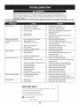
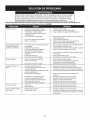
This section addresses minor service issues. To locate the nearest Sears Service Center or to schedule service, simply contact Sears
at 1-800-4-MY-HOME®.
Enginefails to start
1.
2.
3.
4.
Sparkplugwire disconnected.
Fueltank emptyor stale fuel.
Chokelevernot in CHOKEposition.
Faultyspark plug.
1.
2.
3.
4.
5.
Blockedfuel line.
5.
6.
Dirtyair cleaner.
6.
Serviceair cleanerfollowinginstructionsin the
Maintenancesection.
1.
2.
3.
Unit runningwith CHOKEapplied.
Sparkplugwire loose.
Blockedfuel line or stalefuel.
1.
2.
3.
4.
5.
6.
Wateror dirt infuel system.
Dirtyair cleaner.
Carburetornot adjustedproperly.
4.
5.
6.
Movechokeleverto RUNposition.
Connectand tightenspark plugwire.
Cleanfuel line;fill tank with clean,fresh (lessthan
30 days old) gasoline.
Drainfuel tank. Refillwith freshfuel.
Cleanor replaceair cleaner.
ContactSearsservicecenter.
1.
2.
Engineoil levellow.
Dirtyair cleaner.
1.
2.
3.
Carburetornot adjustedproperly.
3.
1.
2.
Brokendriveshaft.
Shippingplugsleft in hydraulichoses.
1.
2.
3.
4.
5.
6.
7.
8.
9.
Setscrewsin couplingnotadjustedproperly.
Looseshaftcoupling.
Gearsectionsdamaged.
Damagedreliefvalve.
Hydrauliclines blocked.
Incorrectoil level.
Damagedor blockedcontrolvalve.
3.
4.
5.
6.
7.
8.
9.
Enginestallsduringsplitting
1.
2.
Lowhorsepower/weakengine.
Overloadedcylinder.
1.
2.
Returnunitto Searsservicecenter.
Donotattemptto splitwoodagainstthe grain.If
enginestallsrepeatedly,contactSearsservicecenter.
LeakingCylinder
1.
2.
Brokenseals.
Scoredcylinder.
1.
2.
Returnunitto Searsservicecenter.
Returnunitto Searsservicecenter.
Enginerunningerratically/
inconsistentRPM (huntingor
surging)
EngineOverheats
Cylinderrod will not move
Connectwireto spark plug.
Filltank with clean,fresh gasoline.
Movechoketo CHOKEposition.
Servicesparkplug followinginstructionsin the
Maintenancesection.
Cleanfuel line.
Fillcrankcasewith properoil.
Serviceair cleanerfollowinginstructionsin the
Maintenancesection.
ContactSearsservicecenter.
Returnunitto Searsservicecenter.
Disconnecthydraulichoses,removeshippingplugs,
reconnecthoses.
Seeoperator'smanualfor correctadjustment.
Correctengine/pumpalignmentas necessary.
Returnunitto Searsservicecenter.
Returnunitto Searsservicecenter.
Flushand cleanhydraulicsystem.
Checkoil level. Refillif necessary.
Returnunitto Searsservicecenter.
NEED MORE HELP?
Y_!I_ fk@ _he answor
a_(! more
o_ _anagem,y_fe_cem,
Find this and at[ your other product manuals online.
* Get answers from our team of home experts.
Get a personalized maintenance plan for your home.
* Find information
and tools to help with home projects.
b:ro'_g_: to yea by S_&_
20
_ £o_° f_ee!
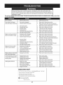
Beforeperforminganytype of maintenance/service,disengageall controlsand stopthe engine.Wait
[
untilall movingparts havecome to a completestop.Disconnectspark plugwire and groundit againstthe [
engineto preventunintendedstarting.Alwayswear safetyglassesduringoperationor whileperformingawl
[adjustmentsor repars.
This section addresses minor service issues. To locate the nearest Sears Service Center or to schedule service, simply contact Sears
at 1-800-4-MY-HOME®.
Reservoirfluid levellow.
1.
Refilltransmissionfluid.
Gear sectionsdamaged.
Excessivepumpinletvacuum.
1.
Returnunitto Searsservicecenter.
2.
3.
4.
5.
6.
Slowenginespeed.
Damagedreliefvalve.
incorrectoil level.
Contaminatedoil.
3.
4.
Makecertainpump inlethosesare clearand
unblocked.Use short,large diameterinlet hoses.
Returnunitto Searsservicecenter.
Returnunitto Searsservicecenter.
7.
8.
Directionalvalve leakinginternally.
[nternallydamagedcylinder.
5.
6.
7.
8.
Checkoil level. Refillif necessary.
Drainoil,clean reservoir,and refill.
Returnunitto Searsservicecenter.
Returnunitto Searsservicecenter.
1.
2.
3.
Smallgear sectiondamaged.
Pumpcheckvalve leaking.
Excessivepumpinletvacuum.
1.
2.
3.
4.
5.
6.
7.
8.
incorrectoil level.
Contaminatedoil.
Directionalvalve leakinginternally.
Overloadedcylinder.
[nternallydamagedcylinder.
4.
5.
6.
Returnunitto Searsservicecenter.
Returnunitto Searsservicecenter.
Makecertainpump inlethosesare clearand
unblocked.Use short,large diameterinlet hoses.
Checkoil level. Refillif necessary.
Drainoil,clean reservoir,and refill.
Returnunitto Searsservicecenter.
7.
8.
Do notattemptto split woodagainstthe grain.
Returnunitto Searsservicecenter.
1.
2.
3.
4.
5.
Engine/pumpmisalignment.
Frozenor seizedpump.
Lowhorsepower/weakengine.
Hydrauliclines blocked.
Blockeddirectionalvalve.
1.
2.
3.
4.
5.
Correctalignmentas necessary.
Returnunitto Searsservicecenter.
Returnunitto Searsservicecenter.
Flushand cleanhydraulicsystem.
Returnunitto Searsservicecenter
Wedgecontinues
to moveforward 1.
whencontrolhandlereleased
DamagedControlValve
1.
Returnunitto Searsservicecenter.
Controlhandledoes notreturn 1.
to neutralwhen releasedfrom 2.
3.
forwardposition
4.
Hydraulicfluidtoo cold.
Hydraulicfluidtoo thick.
Hydraulicfluid contaminated.
Damagedcontrolvalve.
1.
2.
3.
4.
Warmup the engine.
Replacehydraulicfluid.
Replacehydraulicfluid.
Returnunitto Searsservicecenter.
1.
Brokendriveshaft.
1.
Returnunitto Searsservicecenter.
2.
3.
4.
5.
Engine/pumpmisalignment.
Gear sectionsdamaged.
Poorlypositionedshaftseal.
Pluggedoil breather.
2.
3.
4.
Correctalignmentas necessary.
Returnunitto Searsservicecenter.
Returnunitto Searsservicecenter.
5.
Makecertain reservoiris properlyvented.
Will notsplit logs
1.
Slowcylindershaftspeed
1.
whileextendingand retracting. 2.
Engineruns butwoodwill not
split or wood splitstoo slowly
Enginewill notturn or stalls
under lowload conditions
Leakingpumpshaft seal
NEED HORE HELP?
YOu[[S;ndLheanswer andmoreonma_agemy[£e_{om- rex_h'ee!
Find this and aLLyour other product manuals online.
ii _ Get answers
ii
from
our team
of home experts.
Get a personalized maintenance plan for your home.
Find information and tools to help with home projects.
ma, nagemylife
21
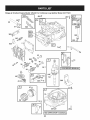
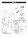
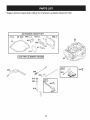
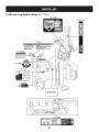
Craftsman
Log Splitter Model 247.77641
@
A
22
A
iVlodel 247
Loc
918-0769A
727-04166
HydraulicCylinder
719-0353
CouplingShield
SquareKey3/16" x.75
HydraulicTube
914-0122
710-1018
Hex CapScrew 1/2-20x 2.75
710-1842
Screw,1/4-20x .38
737-0192
90 DegreeSolidAdapter
718-04392
Coupling,.500
918-0481A
ControlValve
718-04395
Coupling,.875
737-0153
ReturnElbow
735-04103
SpiderCoupling
737-0238
NipplePipe 1/2-14
712-04063
FlangeLock Nut,5/16-18
710-1806
Hex CapScrew 1/2-13x 3.25
781-0097-0637
RearCouplingSupportBracket
719-0550A
WedgeAssembly
781-1024A-0637 FenderMountingBracket
912-3058
Hex Lock Nut, 1/2-20
727-04130
Hose
712-0711
Hex Jam Nut 3/8-24
918-04127
GearPump
710-0459A
Hex CapScrew3/8-24 x 1.5
737-0329
45 DegreeElbowFitting
781-0351
AdjustableGib
727-0502
HighPressureHydraulicHose
936-0116
Fiat Washer.635x.93 x.06
781-0788-0637
TongueAssembly
712-3022
Hex Lock Nut 1/2-13
747-1261
LatchRod
681-04071A-0637 BeamAssembly
781-1045-0637
Latch
710-3056
Hex Screw,5/16-18x 3.25
932-3127
CompressionSpring
710-0502A
Hex WasherScrew3/8-16x 1.250
736-0371
FlatWasher
781-04426-4044
DislodgerBracket
781-0538A
HoseGuard
781-0790-0637
Back Plate
710-3085
HexCap Screw,3/8-16x 3.50
737-04093
inlet Filter
936-0185
FiatWasher,.375x.738x.063
727-0443
ReturnHose3/4" ID x 44" Lg.
747-04539
HydraulicValveControl
726-0132
Hose Clamp5/8"
681-04030
HitchCouplingAssembly
737-0316
Filter Housing
713-0433A
Chain
723-0405
Oil Filter
731-2496A
Fender
734-0873
Hub Cap
911-0813
ClevisPin
714-0162
CotterPin
720-04088
Grip
712-0359
SlottedNut 3/4-16
732-0194
SpringPin
634-0186
WheelAssembly
781-0789-0637
Jack Stand
936-0351
Flat Washer.760ID x.500 OD
915-0120
SpiralPin
737-0312
Adapter3/4-14
710-0650
TT Screw, 5/16-18x 0.875"
781-0526A
Hose Guard
710-0602
TT Screw,5/16-18x 1.00
737-0348A
VentedDipstick
711-04585
ClevisPin
711-1587
ClevisPin
913-04036
ValveHandleLink
781-0690
Lock Rod
914-0111
CotterPin
914-0470
CotterPin
710-0376
HexScrew,5/16-18x 1.00
726-0214
PushCap
736-3010
FiatWasher,.407x .812x .135
732-0583
CompressionSpring
941-0987
RollerBearing
781-04180-0637
Log TrayBracket
921-0168
DustSeal
710-04484
Hex WasherScrew,5/16-18x .750
734-0872
Tire, 16x 4.8 x 8.0
712-04065
FlangeLock Nut,3/8-16
934-0255
TubelessAir Valve
781-04179
-0637
Log Tray
634-0188
RimAssembly
710-04683
HexWasherScrew,3/8-16x 1.000
981-04040A-0637 FrameAssembly
710-0521
Hex Bolt3/8-16x 3
23
Briggs
& Stratton
Engine
Model
126L02
so
For Craftsman
Log Splitter
Model
247.77641
_
51
585_
524
m
i1330
REPAIR
146_
741
306
m
25_
27CJ
@
ls8
I1058
24
OPERATOR'S
MANUAL
i
MANUAL
j
Briggs
& Stratton
Engine
Model
126L02
42s%
For Craftsman
Log Splitter
Model
247.77641
_
836
968
445
443_
843
692 i
633A_
977 CARBURETOR
GASKET SET
104
(3
633A@
633G
276_
130
137_)
95
276 Q
121 CARBURETOR
OVERHAUL
127
KiT
276 O
@
m
276 O
25
°33
0
617
Briggs
& Stratton
Engine
IViodel 126L02
For Craftsman
Log Splitter
IViodel 247.77641
78
497_363_
455 _=_
304
1005
6s _'
58
592
55
s89
456 _
597 _
601
i
1036 EMiSSiONS
LABEL
i
J
26
6O
Briggs
3_
& Stratton
Engine
IViodel 126L02
For Craftsman
Log Splitter
IViodel 247.77641
20
[1329 REPLACEMENT
ENGINE i
m
615 0
404
616
5O5_
27
Briggs
& Stratton
Ref.No.
Engine
IViodel 126L02
PartNo.
For Craftsman
Description
Log Splitter
Ref.No.
IViodel 247.77641
PartNo.
Description
1.
BS-697322
CylinderAssembly
58.
BS-697316
StarterRope(Cut to Req'dLength)
2.
BS-399269
Bushing/SealKit
60.
BS-281434S
StarterRopeGrip
3.
BS-299819St
Oil Seal (MagnetoSide)
65.
BS-690837
Screw(RewindStarter)
4.
BS-493279
EngineSump
78.
BS-691108
Screw(FlywheelGuard)
5.
BS-691160
CylinderHead
81.
BS-691740
MufflerScrewLock
7.
BS-692249t
CylinderHeadGasket
95.
BS-691636
Screw(ThrottleValve)
8.
BS-695250
BreatherAssembly
97.
BS-696565
ThrottleShaft
9.
BS-699125
BreatherGasket
104.
BS-691242tt
Float HingePin
BS-691182
ChokeValve
10.
BS-691125
Screw(BreatherAssembly)
108.
11.
BS-691781
BreatherTube
109.
BS-498593
ChokeShaft
12.
BS-692232t
CrankcaseGasket
117.
BS-498981
MainJet (Standard)
13.
BS-690912
Screw(CylinderHead)
118.
BS-498978
MainJet (HighAltitude)
BS-498260
CarburetorOverhaulKit
15.
BS-691680
Oil DrainPlug
121.
16.
BS-691455
Crankshaft
125.
BS-792253
Carburetor
20.
BS-399781St
Oil Seal (PTOSide)
127.
BS-694468tt
WelchPlug
22.
BS-691092
Screw(EngineSump)
130.
BS-696564
ThrottleValve
23.
BS-691992
Flywheel
133.
BS-398187
CarburetorFloat
24.
BS-222698S
FlywheelKey
134.
BS-398188tt
Needle/SeatValve
25.
BS-791097
PistonAssembly(Standard)
137.
BS-693981it*
Float BowlGasket
--
BS-791326
PistonAssembly(.020"Oversize)
163.
BS-795629t*tt
Air CleanerGasket
26.
BS-791098
PistonRingSet(Standard)
187.
BS-791891
FuelLine (Cut to RequiredLength)
--
BS-791324
PistonRingSet(.020"Oversize)
188.
BS-693399
Screw(ControlBracket)
27.
BS-691866
PistonPin Lock
190.
BS-690940
Screw(FuelTank)
28.
BS-499423
Pistonpin
202.
BS-691829
MechanicalGovernorLink
29.
BS-499424
ConnectingRod
209.
BS-691291
GovernorSpring
BS-692982
ControlBracket
32.
BS-691664
Screw(ConnectingRod)
222.
32A.
BS-695759
Screw(ConnectingRod)
227.
BS-690783
GovernorControlLever
33.
BS-262651S
ExhaustValve
240.
BS-298090S
FuelFilter
34.
BS-262652S
IntakeValve
276.
BS-271716it*
SealingWasher
35.
BS-691270
ValveSpring(Intake)
287.
BS-690940
Screw(DipstickTube)
36.
BS-691270
ValveSpring(Exhaust)
300.
BS-692038
Muffler
37.
BS-694086
FlywheelGuard
304.
BS-493294
BlowerHousing
40.
BS-692194
ValveRetainer
305.
BS-691108
Screw(BlowerHousing)
43.
BS-691997
Governor/OilSlinger
306.
BS-690450
CylinderShield
45.
BS-690548
ValveTappet
307.
BS-690345
Screw(CylinderShield)
46.
BS-691449
Camshaft
332.
712-0318
Nut (Flywheel)
48.
BS-792740
ShortBlock
333.
BS-695711
MagnetoArmature
50.
BS-794305
IntakeManifold
334.
BS-691061
Screw(ArmatureMagneto)
51.
BS-794306t
IntakeGasket
337.
759-3338
SparkPlug
54.
BS-691650
Screw(IntakeManifold)
339.
BS-794797
Tube/ConnectorAssembly
55.
BS-691421
RewindStarter Housing
28
Briggs
& Stratton
Ref.No.
Engine
IViodel 126L02
PartNo.
For Craftsman
Description
Log Splitter
Ref.No.
IViodel 247.77641
PartNo.
Description
347.
BS-691396
RockerSwitch
633A.
BS-6938671-1-* Choke/ThrottleShaft Seal
356.
BS-693010
StopWire
635.
BS-66538S
SparkPlug Boot
358.
BS-794307
EngineGasketSet
668.
BS-493823
Spacer
363.
BS-19069
FlywheelPuller
670.
BS-692294
FuelTankSpacer
365.
BS-692524
Screw (Carburetor)
684.
BS-690345
Screw(BreatherPassageCover)
383.
BS-89838S
SparkPlug Wrench
689.
BS-691855
FrictionSpring
404.
BS-690272
Washer(GovernorCrank)
692.
BS-690579
DetentSpring
425,
BS-690670
Screw (Air CleanerCover)
718.
BS-690959
LocatingPin
443,
BS-692523
Screw (Air CleanerPrimerBase)
741.
BS-790345
TimingGear
BS-499034
MufflerGuard
445,
BS-491588S
Air CleanerCartridgeFilter
832.
455,
BS-791960
FlywheelCup
836.
BS-690664
Screw(MufflerGuard)
456,
BS-692299
PawlFrictionPlate
842.
BS-6910311-
O-RingSeal(DipstickTube)
459.
BS-281505S
RatchetPawl
843.
BS-691895
LeverSleeve
497.
BS-690664
Screw (Stopswitch)
847.
BS-692047
Dipstick/TubeAssembly
505.
BS-691251
Nut (GovernorControlLever)
851.
BS-493880S
SparkPlugTerminal
523,
BS-499621
Dipstick
868.
BS-697338
ValveSeal
524,
BS-6922961-
DipstickTubeSeal
869.
_ BS-691155
525,
BS-495265
DipstickTube
870.
BS-690380
ValveSeat(Exhaust)
529,
BS-691923
Grommet
871.
BS-262001
Guide Bushing(Exhaust)
562,
BS-92613
Bolt(GovernorControl Lever)
--
BS-63709
Guide Bushing(Intake)
564,
BS-690351
Screw (ControlCover)
930.
BS-691919
RewindGuard
584,
BS-697734
BreatherPassageCover
957.
BS-794793
FuelTankCap
585,
BS-6918791-
BreatherPassageGasket
966.
BS-794798
Air CleanerPrimerBase
592.
712-0349
Nut (RewindStarter)
968.
BS-692298
Air CleanerCover
BS-794792
FuelTank
Valve Seat(Intake)
597.
BS-691696
Screw (PawlFrictionPlate)
972.
601.
BS-791850
HoseClamp
975.
BS-796611
Float Bowl
604.
BS-794794
ControlCover
977.
BS-498260
CarburetorGasketSet
608.
BS-497680
RewindStarter
1005.
BS-691346
FlywheelFan
BS-697457
EmissionLabel
613.
BS-691340
Screw (Muffler)
1036.
615.
BS-690340
GovernorShaft Retainer
1058.
BS-MS3260
Owner'sManual
616.
BS-698801
GovernorCrank
1059.
BS-692311
Screw/WasherKit
617.
BS-270344S
1"11 O-RingSeal (intake Manifold)
1210.
BS-498144
Pulley/Spring(Pulley)Assembly
627.
BS-792565
StopswitchBracket
1211.
BS-498144
Pulley/Spring(Spring)Assembly
633.
BS-69132111*
Choke/ThrottleShaftSeal
1330.
272147
RepairManual
tlncluded in EngineGasketSet, Key.No. 358
ttlncluded in CarburetorOverhaulKit, Key.No. 121
*includedin CarburetorGasketSet, Key.No. 977
29
Craftsman
Log Splitter Model 247.77641
777S32061
777D14914
777S33112
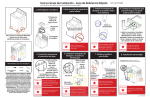
MOVING LO_ SPLITTER BY HAND
" A_a h eoup_r toC_ass_or hZ_herhitch w_th2" bal_,
o Look
beam
in horizontal
= Lo_k
iack
s_and
in down
= DO not
attempt
to
move
, If coupler
adiustme_t
_S needed
_efer
,Raisejackstandandlaichsecu_elyinfutlupposltion.
o Attach
safety
chains
to tow
vehicle,
or
down
TOWING
•
LOCk
a slope
LOG
beam
by
position,
position
log
splitter
hand
up
*
Do
•
High
C_eck
towing
SPLITTER
in
hori_ntal
position,
not
tow
faster
than
45
to
owt_er's
manu_t,
mph,
speed
m_y
cause
loss
oca
sae
nd
edea
on ahy
public
road.
of
control.
equ
emensbeoe
777S33200
DOHOT
USE E85 OR FUEL
CuR'rAMMG MORE
777X43688 TUAR
10%
ETRAROL
777i23022
level Pump
be
ruined.
Change
777S32605
30
Congratulationson makinga smartpurchase.YournewCraftsman@
productis designedand manufacturedfor yearsof dependableoperation. But likeall products,it may requirerepairfrom time to time.That's
whenhavinga RepairProtectionAgreementcansave youmoneyand
aggravation.
Here'swhat the RepairProtectionAgreement*includes:
* Expert service byour 10,000professionalrepairspecialists
o Unlimitedserviceand no chargefor partsand laboron all
coveredrepairs
o Product replacementup to $1500if yourcoveredproductcan't be
fixed
• Discountof 10%from regularprice of serviceand relatedinstalled
parts notcoveredby theagreement;also, 10%off regularpriceof
preventivemaintenancecheck
• Fast help by phone- we call it RapidResolution- phone support
from a Searsrepresentative.Thinkof usas a "talkingowner's
manual."
31
Onceyou purchasethe Agreement,a simplephonecall is all that it
takesfor youto scheduleservice.Youcan call anytimedayor night,or
schedulea serviceappointmentonline.
The RepairProtectionAgreementis a risk-freepurchase.If youcancel
for any reasonduringthe productwarrantyperiod,wewill providea full
refund.Or,a proratedrefundanytimeafter the productwarrantyperiod
expires.Purchaseyour RepairProtectionAgreementtoday!
Somelimitationsand exclusionsapply. For pricesand additional
informationin the U.S.A. call 1-800-827-6655.
*Coverage in Canadavaries on some items. Forfull details call
Sears Canadaat 1-800-361-6665.
Sears Installation Service
ForSearsprofessionalinstallationof homeappliances,garagedoor
openers,waterheaters,and othermajorhomeitems,in the U.S.A.or
Canadacall 1-800-4-MY-HOME®.
32
33
34
Garantia .......................................................
Instrucciones De Seguridad .....................
Ensamble ..................................................
Funcionamiento ........................................
Servicio y ajustes ......................................
Mantenimiento ..........................................
Pagina 35
Pagina 36-39
Pagina 40-43
Pagina 44-47
Pagina 48
Pagina 49-51
Almacenamiento ....................................... Pagina 52
Solucion De Problemas ............................ Pagina 53-54
Acuerdo De Protecci6n Para Reparaciones
.............................................................
Pagina 55
NOmero de servicio ..................... Cubierta posterior
CRAFTSMAN
COMPLETA
GARANTIA
Cuando son operados y mantenidos de acuerdo con tas instrucciones suministradas en su totalidad, si este registro
Craftsman bifurcador falla debido a un defecto de material o mano de obra dentro de un a_o a partir de ta fecha de compra,
ltame al 1-800-4-MY-HOME ® fibre que disponga la reparaci6n ( si ta reparaci6n o ta sustituci6n resulte imposibte).
Esta garantia se aplica s61o para 90 dias a partir de la fecha de compra si este registro separador es utitizado para
prop6sitos comerciales o de alquiter.
Esta garantia solo cubre defectos de material y mano de obra. Sears no pagara per:
*
*
*
*
*
*
*
*
Los etementos que se desgastan durante et uso normal, incluyendo pero no limitado a la bujia, depurador de aire,
cinturones, y fittro de aceite.
Norma de servicios de mantenimiento, cambios de aceite, o afinaci6n
Cambio de neumaticos de sustituci6n o reparaci6n de pinchazos causados por objetos externos, tales como clavos,
espinas, tocones, o de vidrio.
De neumaticos o ruedas de reemplazo o ta reparaci6n como consecuencia de desgaste normal, accidente, o de la mala
operaci6n o mantenimiento.
Reparaciones que scan necesarias a causa de los abusos det operador, incluyendo pero no limitado a los da_os
causados por el exceso de vetocidad det motor, o de objetos que impactan doblar et marco, et eje sinfin, etc.
Reparaciones que scan necesarias a causa de la negligencia det operador, inctuyendo pero no limitado a, productos
etectricos y mecanicos de los da_os causados por almacenamiento inadecuado, falta de utilizaci6n de la categoria
apropiada y la cantidad de aceite de motor, o et fracaso para mantener et equipo de acuerdo con las instrucciones
contenidas en el manual del operador.
Motor (sistema de combustible), ta limpieza o reparaciones causadas por los combustibles decidida a ser contaminados
o oxidado (rancio). En general, et combustible debe ser utitizado dentro de los 30 dias siguientes a su fecha de compra.
Normal desgaste y deterioro de los acabados exteriores, o ta etiqueta det producto de reemplazo.
Esta garantia s61o se aptica mientras que este producto esta dentro de los Estados Unidos.
Esta garantia le otorga derechos legales especificos,
estado.
y usted tambien puede tener otros derechos que varian de estado a
Sears, Roebuck and Co., Hoffman Estates, IL 60179
Serie de motor:
126L02=0531
Tipo del aceite de motor:
SAE 30
Cap. de aceite del motor:
20 Onzas
Capacidad de combustible:
1.5 Cuartos
Bujia (separaci6n de .030"): Champion RJ=lgLM
Liquido hidraulico:
Dexron III / 3.0 gal
N_mero
NQmero
de modelo ....................................................
de serie ........................................................
Fecha de compra ......................................................
Para referencia
futura
registrar
el nQmero
de serie
y la fecha
35
de compra
y guardar
en un lugar
seguro.
Esta m_quina fue construida para set operada de acuerdo
con las reglas de seguridad contenidas en este manual.
AI igual que con cualquier tipo de equipo motorizado, un
descuido o error pot parte del operador puede producir
de instrucciones importantes de seguridad que
La
presencia
de este
sfmbolo
se trata
se deben
respetar
para
evitar indica
poner que
en peligro
su seguridad personal y/o material y la de otras
personas. Leay siga todas las instrucciones de
este manual antes de poner en funcionamiento
esta m_quina. Si no respeta estas instrucciones
podrfa provocar lesiones personales. Cuando
vea este sfmbolo, ipreste atenci6n a la
advertencia!
PROPOSICION
lesiones graves. Esta m,iquina es capaz de amputar manos y
pies y de arrojar objetos con gran fuerza. De no respetar las
instrucciones de seguridad siguientes se pueden producir
lesiones graves o la muerte.
Su responsabilidad--Restrinja
el uso de esta m_iquina
motorizada alas personas que lean, comprendan y respeten
las advertencias e instrucciones que aparecen en este
manual yen la m_iquina.
65 DE CALIFORNIA
El escapedel motorde este producto,algunosde sus componentes
y algunoscomponentesdel vehiculocontieneno liberansustancias
quimicasque el estadode Californiaconsideraque puedenproducir
c_ncer,defectosde nacimientou otros problemasreproductivos.
GUARDE
ESTAS
INSTRUCCIONES
CAPACITACION
1.
2.
3.
4.
5.
6.
7.
8.
9.
Lea,entienday cumplatodaslas instruccionesincluidasen la
m_quinayen el(los)manual(es)antes de intentarrealizarel
montajede la unidady utilizarla.Guardeeste manualen un
lugar seguropara consultasfuturasy peri6dicas,asi como para
solicitarrepuestos.
Familiaricesecontodos los controlesy con el usoadecuadode
los mismos.Sepac6mo detenerla m_quinay desengancharlos
controlesr_pidamente.
No permitanuncaque losniEosmenoresde 16aEosutilicenesta
m_quina.Losni_osde 16a_osen adelantedebenleery entender
las instruccionesde operaci6ny normasde seguridadcontenidas
en este manualyen la m_quinay debenserentrenadosy
supervisadospor un adulto.
Nuncapermitaque los adultosoperenesta m_quinasin recibir
antesla instrucci6napropiada.
Muchosaccidentesocurrencuandom_s de una personahace
funcionarla m_quina.Si un pe6n Io est_ ayudando
a cargar lostroncos,nuncaactiveel control hastaque el pe6n se
encuentrepor Io menosa 10 piesde distanciade
la m_quina.
Mantengaa losobservadores,mascotasy ni_ospor Iomenosa 10
piesde la m_quinasiempreque est_funcionando.
Nuncapermitaque ningunapersonase desplaceen
la m_quina.
Nuncatrasladecargasen esta m&quina.
36
Lasm&quinasrompetroncoshidr&ulicasdesarrollanaltas
presionesde fluidoduranteel funcionamiento.Si salefluido a
trav_sde la aberturade un orificiode pasadorpuede penetrar
en la piel y causarleenvenenamiento
de la sangre,gangrenao
la muerte.Presteatenci6nalas siguientesinstruccionesen todo
momento:
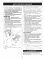
a.
Nocontrolelas fugascon la mano.
b.
Noopere la m&quinasi las mangueras,los accesorioso
los tubos est&ndeshilachados,enroscados,agrietadoso
daSados.
c.
Detengael motory libere la presi6ndel sistemahidr&ulico
haciendopasarla palancade controlde la valvulade la
posici6nde avancea la de retrocesovariasvecesmientras
el motorno est&en marcha;regresandoa la posici6nneutral
antes de realizarla reparaci6no el ajustede los accesorios,
las mangueras,los tubos u otros componentesdel sistema.
d. Noajuste losvaloresde presi6nde la bombao v&lvula.
10. Lasfugas se puedendetectarpasandoun cart6no maderasobre
el &reasospechosa,usandoguantesde protecci6ny anteojosde
seguridad.Fijesesi el cart6no la maderapierdencolor.
11. Si es lastimadopor un escapede fluido,consultea un m_dico
de inmediato.Si no se administratratamientom_dicoadecuado
inmediatamentese puede produciruna infecci6no reacci6n
grave.
12. Mantengala zonadel operadory el &reaadyacentedespejadas,
para poderestar paradocon firmezay seguridad.
13. Si la rn_.quinaest,. equipadacon un motorde cornbusti6ninterna
y existela intenci6nde usarlacerca de un terrenoagrestecubiertode bosque,arbustoso pasto,el escapedel motordebe estar
provistode un arnortiguadorde chispas.AsegQresede respetar
todoslos c6digoslocales,estatalesy federalesaplicables.Lleve
el equiparnientoadecuadopara cornbatirincendios.
14. Esta rn_.quinasedebe utilizar Qnicarnente
para cortar rnadera,no
la usecon ningQnotroprop6sito.
NIANEJO SEGURO
DE LA GASOLINA
Paraevitarlesionespersonaleso da_os rnaterialesseasurnarnente
cuidadosoal rnanipularla gasolina.La gasolinaes surnarnente
inflarnabley sus vaporespuedencausarexplosiones.Si se derrarna
gasolinaencirnao sobrela ropa se puedelesionargravernenteya que
sepuede encender.L_.vesela piel y c_.rnbiesede ropade inrnediato.
•
Utilices61olos recipientesparagasolinaautorizados.
•
Apaguetodos loscigarrillos,cigarros,pipasy otrasfuentesde
ignlclon.
Nuncacarguecombustibleen la rn_.quinaen un espaciocerrado.
15. Siga las instruccionesdel(de los) rnanual(es)entregado(s)con
cualquieraccesoriode esta rn_.quina.
•
PREPARATIVOS
•
Nuncasaquela tapadel combustibleni agreguecombustible
rnientrasel motorest,. calienteo en rnarcha.
1.
Siernpreusezapatosde seguridado botasreforzadas.
2.
Siernpreuseanteojoso antiparrasde seguridadcuandohace
funcionaresta rn_.quina.
No usenuncajoyas ni vestirnentafioja que pudieranquedar
atrapadasen laspartes rn6vileso giratoriasde la rn_.quina.
Cornpruebeque la rn_.quinaest_ sobresuelonivelado,seco y
resistenteantesde suoperaci6n.
•
Dejeque el motor se enfriepor Io rnenosdosrninutosantes de
volvera cargarcombustible.
•
NuncaIleneen excesoel tanquede combustible.Lleneel tanque
no rn_.sde 1/2pulgadapor debajode la basedel cuellodel filtro
paradejar espaciopara la expansi6ndel combustible.
Vuelvaa colocarla tapadelcombustibley ajQstelabien.
Siernprebloqueelas ruedaspara evitarque sernuevaaccidentalrnentey trabe la viguetaya sea en posici6nhorizontalo vertical.
Siernpreopere la rn_.quinadesdela(s) zona(s)del operadorque
se especificanen el manual.Vea la Figura1.
•
Lirnpieel combustibleque se hayaderrarnadosobreel motory
el equipoy rnuevala rn_.quinaa otra_.rea.Esperecinco rninutos
antes de encenderel motor.
•
Nuncaguarde la rn_.quinao el recipientede combustibleen un
espaciocerradodondehayafuego,chispaso luz piloto,corno
porejernplode calentadoresde agua,calefactoresde arnbientes,
hornos,secadoresde ropau otrosaparatosa gas.
Dejeque la rn_.quinase enfriepor Iornenos
5 rninutosantes de guardarla.
3.
4.
5.
6.
_
Vertical
•
"]
•
FUNCIONAIVilENTO
1.
2.
3.
Noutilice la rn_.quinabajola infiuenciade alcohol,drogas
o rnedicarnentos.
4.
Nuncaperrnitaa nadie operaresta rn_.quinasin recibirantes la
instrucci6napropiada.
Siernpreopere la rn_.quina
con todoel equiparnientode seguridad
en su lugary en condiciones.AsegQresede que todos los
controlesfuncionenadecuadarnentepara una operaci6nsegura.
5.
Horizontal
6.
Figura1
7.
Antesde cortar los troncosconesta rn_.quina
se les debencortar
los extrernosen escuadra.
8.
Use la rn_.quinarornpetroncosa la luz del dia o con buenaluz
artificial.
Antes de poneren rnarchaesta rn&quina,repaselas"Medidasde
seguridad".Si no se respetanestasnorrnasse puedenproducir
lesionesgravestantoal operadorcornoa los observadores.
Nuncadeje la rn_.quinaen funcionarnientosin vigilancia.
Zonadeloperador
•
Posici6nhorizontalde funcionarniento:P_.resedel lado de la
palancade controlde la rn_.quinarornpetroncosy estabilice
el troncocornose indica,si es necesario.Vea la Figura1.
•
Posici6nverticalde funcionarniento:P_.resedelantede la
rn_.quinarornpetroncosy estabiliceel troncocornose indica,
sies necesario.Vea la Figura1.
Cuandoestabilizael troncocon la rnanoizquierda,quitela rnano
despu_sde que la cuSaest_justo en contactocon el troncoo
puede lesionarsegravernente.
37
7.
8.
9.
Cuandocargueun tronco,siernprecoloquelas rnanosa los
ladosdel misrno,no en los extrernos,y no use nuncael pie para
estabilizarun tronco.Si no respetaestasinstrucciones,se puede
producirel aplastarnientoo la arnputaci6nde dedos,dedosde los
pies, rnanoso pies.
Use Qnicarnentela rnanoderechaparaoperar loscontroles.
Nuncaintentecortar rn_.sde un tronco a la vez.
10. Paralos registrosque no est_.ncortadosen _.ngulorecto,el
extrernornenoscuadradode la sesi6nse debe colocarhaciael
rayoy la curia,y el extrernocuadradocolocadohaciala placa
terminal.
8.
colocaentreel registroy la placaterminalo tierra.
12. Siernprernantengalos dedosalejadosde cualquierhendidura
que se abra en el troncornientrasrealizael cortado.Estas
separacionessepuedencerrarcon rapidezy atrapar
o arnputardedos.
13. Mantengalirnpiael _.reade trabajo.Retireinrnediatarnentela
rnaderacortadaque quede alrededorde la rn_.quinapara no
tropezarsecon la rnisrna.
Paraevitarincendios,
lirnpiela suciedady grasade las _.reas
del motory del silenciador.Si el motorest,. equipadocon un
silenciadorcon arnortiguadorde chispas,lirnpieloe inspecci6neloregularrnentesegQnlas instruccionesde losfabricantes.
Reernpl_.celo
si est,. dafiado.
Peri6dicarnentecontroleque todas lastuercasy pernos,abrazaderas de rnanguerasy accesorioshidr_.ulicosest_najustados,
para verificarque el equipose encuentraen condicionesde
trabajoseguras.
Controletodos losprotectoresy escudosde seguridadpara
verificarque se encuentrenen posici6nadecuada.Nuncaopere
la rn_.quinasi se han retiradolosprotectoreso escudosde
seguridadu otrosdispositivosde protecci6n.
La v_.lvulade descargade presi6nvienepreconfigurada
de f_.brica.Nola ajuste.
Nointentenuncamoverla rn_.quina
en terrenoen pendienteo
desparejosin un vehiculode rernolqueo sin ayudaadecuada.
Potsu seguridad,carnbietodas las piezasdafiadaso desgastadas inrnediatarnenteutilizandoQnicarnenteequipodel fabricante
original('OEM'). El uso de piezasque no curnplencon las especificacionesdel equipooriginalpuede resultaren rendirniento
inadecuadoy puedeponer en peligrola seguridad.
9.
14. Nocarnbiela configuraci6ndel reguladordel motorni acelere
dernasiadoel motor.El reguladordel motorcontrolala velocidad
rn_.xirnade funcionarnientosegurodel motor.
15. Nuncarnuevala rn_.quinarnientrasel motorest,. en funcionarniento.
16. Esta rn_.quinano se debe rernolcaren ningunacalle, rutao
carninopOblicosinverificarlos requisitosaplicablesa los vehiculos segQnlas reglarnentaciones
federales,estataleso localesque
se encuentrenen vigencia.Cualquierautorizaci6no rnodificaci6n
que se deba realizar,por ejernplo,en relaci6ncon lucestraseras,
etc.,es responsabilidadexclusivadel cornprador.Si en su estado
se exigeuna "Declaraci6n
de Origen",consultecon su distribuidorlocal.
17. No rernolquela rn_.quinaporencirnade las 45 rnph.
18. Vea la secci6n'Transportede la rn_.quinarornpetroncos'
de este manualparaconsultarlas instruccionesde rernolque
adecuadasdespu_sde habercurnplirnentadotodos los requisitos
federales,localeso estatales.
2.
6.
7.
AIdividirextra grandeo desigualregistros,el registrodebe
set estabilizadoconcutlasde rnaderao de rnaderadividida
1.
4.
5.
11. Cuandocorte en posici6nvertical,estabiliceel troncoantesde
moverla rnanijade control.Corte segQnse indicaa continuaci6n:
•
Coloqueel troncoen la placadel extrernoy girelo hastaque
se inclinecontra la viguetay quedeestable.
MANTENIMIENTO
3.
Y ALIVlACENANIIENTO
Nornodifiqueesta rn_.quina
de ning_nrnodo;si se realizan
rnodificacionestalescornoagregadode una cuerdao alargador
a la rnanijade control,o el aurnentodel anchoo la alturade la
curia, se puedenproducirlesionespersonalesgraves.
10. SegOnla Cornisi6nde Seguridadde Productosparael Consurnidorde los EstadosUnidos(CPSC)y la Agenciade Protecci6n
Arnbientalde los EstadosUnidos(EPA),este productotieneuna
vida dtil mediade siete(7) afios o 130 horasde funcionarniento.
AI finalizarla vida dtfl mediahaga inspeccionaranualrnenteesta
unidad por un distribuidorde servicioautorizadoparacerciorarse
de que todos lossisternasrnec_.nicosy de seguridadfuncionan
correctarnentey no tienenexcesivodesgaste.Si no Io hace,
puedenproducirseaccidentes,lesioneso la rnuerte.
AMORTIGUADOR
DE CHISPAS
Esta rn_.quina
est,. equipadacon un motorde cornbusti6ninternoy
no debe ser utilizadaen o cercade un terrenoagrestecubiertopor
bosque,rnalezaso hierbaexceptoque el sisternade escapedel
motorest_ equipadocon un arnortiguadorde chispasque curnpla
con lasleyeslocaleso estatalescorrespondientes(en caso de
existir).
Si se utiliza un arnortiguadorde chispasel operadorIo debe rnantener
en condicionesde usoadecuadas.Enel Estadode Californialas
rnedidasanteriorrnenternencionadassonexigidaspor Icy (Arficulo
4442 del C6digode RecursosPOblicosde California).Esposible
que existanleyessirnilaresen otros estados.Lasleyesfederalesse
aplicanen territoriosfederales.
Puedeconseguirel arnortiguadorde chispasparael silenciadora traves
de sudistribuidorde rnantenirniento
de rnotoresautorizadorn_.scercano
o poni_ndoseen contactoconel departarnentode servicios,RO. Box
361131Cleveland,Ohio44136-0019.
Detengael motor,desconectela bujiay haga rnasacontrael
motorantesde lirnpiaro inspeccionarla rn_.quina.
Detengael motory liberela presi6ndel sisternahidr_.ulico
haciendopasarla palancade controlde la v_.lvulade la posici6n
de avancea la de retrocesovariasvecesrnientras
el motorno est,. en rnarcha;regresandoa la posici6nneutral
antesde realizarla reparaci6no el ajuste de los accesorios,las
rnangueras,los tubosu otroscornponentesdel sisterna.
38
SAFETY SYMBOLS
This pagedepictsand describessafety symbolsthat may appearon this product. Read,understand,and follow all instructions
on the machine
beforeattemptingto assembleand operate.
LEA LOSMANUALESDELOPERADOR
Lea,entienday curnplatodas las instruccionesincluidasen losrnanualesantes de realizar
el rnontajede la unidady utilizarla.
ADVERTENCIA--RIESGODEAPLASTAMIENTO
Mantengalasrnanosalejadasde la cuSa,la placadel extrerno,la rnaderaque est_ parcialrnente
cortaday las piezasrn6viles.
OBSERVADORES
Mantengaa los observadores,ayudantesy niSospor Iornenosa 10 piesde distancia.
OPERADORONICO
%1o debe operarla rn_.quinauna personaa la vez.El adultoque cargay estabilizael troncodebe ser
la personaque opere la rnanijade control.
ADVERTENCIA--FLUlDOPRESURIZADO
Nuncacontrolecon las rnanossi los tubostienen perdidas.El fiuidoa presi6nelevadapuedesalir
a travesde la aberturade un orificiode pasadory causarlelesionesgravesal penetraren la piel y
causarleenvenenarnientode la sangre.
PROTECCIONOCULAR
Siernpreuseanteojoso antiparrasde seguridadcuandohacefuncionaresta rn_.quina.
ADVERTENCIA--CUNAMOVIL
Mantengalasrnanosalejadasde la cuba y de las piezasrn6viles.
39
Retiredel gatoque est,. sobrela leng_Jeta
la abrazaderade
resortey el pasadorde horquillay luegogire el gato haciael
suelo, hastala posici6nde operaci6n.Vea la Figura1.
NOTA: Eldivisor del registrose enviacon aceitede motoren el motor.
Sin embargo,debe cornprobarel nivelde aceiteantes de operar.
Tengacuidadode no Ilenardernasiado.
NOTA:Todaslas referenciasque contieneeste manualsobrelos lados
derechoo izquierdoy delanteroy traserode la rn_.quinarornpetroncos
se hacenobservandola rnisrnades@la posici6nde operaci6n.Si
existieraalgunaexcepci6n,la rnisrnaser_.especificada.
COMO DESEMBALAR
Y MONTAR
MAQUINA ROMPETRONCOS
Abrazadera
de resorte
LA
H ERRAMIENTAS NECESARIAS: Anteojosde seguridad,
guantesde cuero,cortadoresde alarnbre,barretay/o un rnartillode
orejas.
1. Use una barretapara afiojary extraerla tapade la caja.
2.
3.
4.
Chavetade
horquilla
Gato
Use una barretay un rnartillopara extraerlos costadosde la
caja, cornenzandopor loscostadoscortos(o el lado izquierdoy
derechode la rn_.quinarornpetroncos).Ponga
a un lado los costadosde la caja para evitarlesiones.
En el frentede la caja el conjuntode la lengOetaest&sujetoen el
interiorde la cajacon un precintoparacables.Corte
el precintopara cablespara extraerla leng(Jeta.
Figura1
,
9.
Extraigala cubbrta pl&sticagrandey desc&rtela.
Sujeteel gatoen sulugar conel pasadorde horquilla
y la abrazaderade resorte.Vea la Figura1.
Con la rn_.quinarornpetroncostodavia sujetaa la basede la
caja, extraigados pernoshexagonalesy tuercashexagonalesdel
soportedel tanquey extraigael trozode rnaderaque est&en los
soportesdel tanque.Veala Figura2.
NOsaquernaderani corte las tiras que sujetanla rn&quinarompetroncoso sus cornponentesa dicharn_.quinao la cajaen este
rnornento.Saque solarnentelas tirasy/o la rnaderacuandose le
indiqueque Io haga.
5.
6.
Inspeccioneel rondode la caja paradetectargrapaso astillasde
rnaderasobresalientesy extr_.igalas.
Quitecualquierpartesueltaque se incluyacon la rn_.quina
rornpetroncos(el manualdel operador,etc.).
NOTA: Noextraigala rnaderaque est,.entre la cuba y la placadel
extrerno,los pernosque sujetanla placadel extrernoa la basede la
cajay la tira grandede metalque sujeta la rn_.quinarornpetroncosa la
basede la caja, hasta que se le indiqueque Io haga.
Figura2
10. Alinee losorificiosde la leng_Jeta
con los orificiosdel soportedel
tanquey fijela con los elernentosde ferreteriaque se acabande
retirar.Vea la Figura2.
NOTA: La rnanguerade alta presi6n,que seextiendedesdela bornba
de engranajehasta la parteinferiorde la v_.lvulade control,debeestar
por encirnadel conjuntode la bng(Jeta.
40
14. Desconecteel bandejade troncosde la viguetaque est,. al
costadode la v_.lvulade controlextrayendolosdos tornillos
de las arandelashexagonalesque Io sujetana la viguetay los
dos tornillosde las arandelashexagonalesde la vigueta.Vea la
Figura5.
11. La rn_.quinarornpetroncosse envfacon la viguetaen posici6n
vertical.Extraigalos pernoso las tiras que sujetanla placadel
extrernoa la basede la caja.
12. Tirehaciaafueradel bloqueode viguetavertical, r6telohacia
atr_.sy gire la viguetaa la posici6nhorizontalhastaque quede
trabada,asegur_.ndose
de evitarlos posiblespuntosde apriete.
Veala Figura3.
Figura5
15. Levantey desliceel cilindrohaciaarriba hastael topede la
viguetay dentrode los soportessoldados.Veala Figura6.
Figura3
Tengarnuchocuidadoal subiry bajarla viga,ya que es bastante
pesado.Despu_sde haberuna segundapersonaayudara subir
o bajarla vigase recornienda.AsegQresede rnantenerlasrnanos
alejadasde cualquierpuntode pellizcoposible.
13. Desconecteel liberadordel soportesoldadode vigueta retirando
los seis tornilloshexagonales.Veala Figura4.
Figura6
16. Coloqueel liberadorencirnadel rnontajede la cuSay fijelo en los
soportessoldadoscon loselernentosde ferreteriaque extrajo
previarnente.Vea la Figura4.
NOTA:Unavez apretadoslos seis tornilloshexagonales,puedehaber
una pequeSaseparaci6nentreel liberador
y los soportessoldados.Estaseparaci6nes normal.
Figura4
41
17. Vuelvaa colocarel bandejade troncosal costadode la vigueta
con la vAIvulade control,alineandolos orificiosdel bandejacon
los orificiosde la vigueta.Veala Figura7.
Aceite
1.
Quitarvarillade Ilenadode aceite.
2.
El niveldel aceiteasegurandosede no frotar la varillade
rnedici6na Io largode las paredesinterioresdel tubo de Ilenado
de aceite.Estodarfacornoresultadouna lecturafalsa varillade
rnedici6n.Vuelvaa Ilenarhastala rnarcaFULLde la rnisrna,si es
necesario.Vuelvaa colocarla varillay apriete.
Si es necesario,con la cortadorasobreel niveldel suelo,utilice
un ernbudopara Ilenarel motorcon aceitehasta la rnarcaFULL
de la rnisrna.Tengacuidadode no Ilenardernasiado.Sobrellenado harAnque el motorde furnarrnuchoy resultarAen un
rendirnientodel motor.
3.
4.
El niveldel aceitetres vecesantes de arrancarel motorpara
asegurarsede que hayasconseguidouna varillade lectura
precisa.El funcionarnientodel motorcon pocoaceite puede
provocarda_osen el motorperrnanente.
Gasolina
1.
2.
Quite la tapade combustibledesdeel tanquede combustible.
AsegQresede que el recipientedel que se vierte la gasolinaest_
lirnpioy librede 6xidoo partfculasextra,as. Nuncausegasolina
que puedeserduro de largosperfodosde alrnacenarnientoen su
envase.Gasolina,que ha estadoen reposoduranteun perfodo
mayorde cuatrosernanasdebeconsiderarseviciado.
3.
Lleneel tanquede combustiblecon aproxirnadarnente1,5litros
de gasolinalirnpia,fresca,con un rnfnirnode 85 octanos.
Figura7
18. Controlesi haygrapasy extrAigalasde la basede la cajaya que
puedenperforarel neurnAtico.
19. Corte la tira de metalque sujeta la rnAquinarornpetroncosa la
basede la aja y extraigala rnaderaque estAdebajo del motory/o
cualquierotrarnadera,luego hagarodar la rnAquinafuerade la
basede la caja de ernbalaje.
Preparaci6n
1.
CONFIGURACI6N
2.
Presi6n
de los neurnaticos
de la rnaquina
rornpetroncos
Lubriqueel Areade la viguetadonde se desplazarAla cuba de
corte con aceitede motor.No usegrasa.
Retirela varilladel dep6sitoventeadaque se encuentradelante
del motor,sobreel tanquede dep6sito.Vea la Figura8.
La presi6nde operaci6nmaximarecornendadaes 30 psi. En ninguna
circunstanciasuperela presi6nen psi recornendadapor el fabricante.
Mantengala rnisrnapresi6nen todos losneurnAticos.
causarlesiones raves.
Llenado
de gasolina
y aceite
Realiceel rnantenirnientodel motorcon gasoNnay aceite corno
se expNcaen el manualdel motorque se entreg6con la rnAquina
rornpetroncos.Lea las instruccionesconatenci6n.
Tengarnuchocuidadoal trabajarcon gasolina.La gasoNnaes
sumarnenteinfiarnabley susvaporespuedencausarexplosiones.
I Nuncaagreguecombustiblea la rnAquinaen interioreso rnientrasel
l motorestAcalienteo en funcionarniento.
NOTA: Esposibleque su rnAquinarornpetroncosseenvfecon aceite
en el motor.UstedDEBEcontrolarel nivelde aceiteantes de hacer
\
Figura8
NOTA: La rnAquinarornpetroncosvienede fAbricaIlenahastael nivel
funcionarla rnAquina.Tengacuidadode no Nenaren exceso.Se
operativocorrectoconfluido hidrAulicoShell Tellus®32. Sin embargo,
puedeagregargasoNnaal motorcuandola rnAquinarornpetroncosse
usted DEBEcontrolarel nivelde fluidoantes de ponerlaen funcionaencuentraen posici6nhorizontalo vertical.Sin embargo,es posible
rniento.Si no estA Ileno,realicelos siguientespasos:
que resulternAsfAcilcuandola unidadse encuentraen posici6n
vertical.
42
Granpartedel liquidooriginal seha desplazadoen el cilindroy los
tubos.AsegOresede volvera Ilenarel dep6sitopara evitar que se
dafie la bornbahidr_.ulica.
3.
Controleel nivelde liquidocon la varillade nivel.Vea la Figura8.
No Ileneel dep6sitoen exceso.
NOTA:Entrelos fluidosaprobadosse encuentranfiuidohidr_.ulico
Shell Tellus®32, fluidopara transrnisionesautorn_.ticasDexron®III
/ Mercon®,aceitehidr_.ulicoPro-SelectTM AW-32o aceitehidr_.ulico
32 grado de viscosidadIOWAW-lSO.No se recorniendarnezclarlos
fluidos,para Ilenarhastacornpletarel tanquede dep6sitodurantela
configuraci6ninicial debeusar Onicarnenteel fluidohidr_.ulicoShell
Tellus®32.
4.
5.
6.
7.
8.
Vuelvaa colocarla varillade nivelventeaday apri_telabien hasta
que el topede las roscasquedeal ras del topedel tubo.
Desconectela bujia y cebela bornbatirandodel arrancadorde
retrocesohastael rn_.xirno.Repitaeste pasoaproxirnadarnente
10 veces.
Vuelvaa conectarel cablede la bujia y arranqueel motor seg_n
las instruccionesdel manualdel operadordel motor.
Use la rnanijade control paraengancharla cura en la posici6n
de extensi6nmaxima.Luegoretraigala cura.
Vuelvaa Ilenarel tanquesegQnIo especificadoen la varillade
nivelde sernecesario.
NOTA:La falta de Ilenadodel tanqueanulala garantiade
la rn_.quinarornpetroncos.
9.
Extienday retraigala curia12 cicloscornpletosparaelirninarel
aireatrapadoen el sisterna(el sisternaes "autopurgante").
10. Vuelvaa Ilenarel dep6sitodentrodel rangoque figuraen la
varillade nivelde ser necesario.
NOTA:Partedel Ifquidopuede rebasarel tap6nde cierrede la tuberia
de ventilaci6nya que el sisternaacurnulacalory el liquido se expande
y buscaun nivelbalanceado.
43
Cilindro
Liberadorde
la rnadera
Manijade
control
Cuba
/ BIoqueodela
viga horizontal
Montajede la vigueta
Findel mural
gOeta
Gato
Controlesdel motor
jL
delarran_o_
tandeja
Bloqueo
detroncos
de la viga
vertical Tanquedel
dep6sito
Control
_
del cebador
L____
Fi. ura 9
Farniliaricesecon todos loscontrolesy sucorrectofuncionarniento.
Sepa c6rnodetenerla rn_.quinay c6rnodesconectarloscontroles
r_.pidarnente.
Lea este manualdel operadory las reglasde seguridadantesde
poneren funcionarnientola rn_.quina
cortadorade rnadera.Compare
las ihstracionesque aparecena continuaci6ncon su equipopara
farniliarizarsecon la ubicaci6nde los distintoscontrolesy ajustes.
Guardeeste manualparaconsultasfuturas.
usta o Io repar&
BLOQUEOS
iVlANIJA DE CONTROL
DE LAS VIGAS
Estasdostrabas,se usanpara ajustarla viguetaen posici6n
horizontalo en posici6nvertical.La trabade la viguetaverticalest,.
ubicadasobrela rn_nsulade los dep6sitos.El bloqueode la vigueta
horizontalest,. ubicadosobreel soportedel sujetadorde la vigueta.
La manijade controlse usa para moverla cubahaciaarriba y hacia
abajo paracortar rnadera.La rnanijade controltiene tres posiciones:
adelante,neutral,y rnarchaatr_.sVea la secci6nUso de la rn_.quina
rornpetroncospara obtenerinstrucciones.
CUbA
LIBERADOR
La cuSase usapara cortar la rnadera.
El liberadorde maderaest,. dise_adopara sacarde la cuba la rnadera
parcialrnentecortada.Estopuede sucedercuandosecorta rnaderade
gran di_.rnetroo recienternentecortada.
LENGUETA
La lengOetaseusa para acoplara un vehiculode rernolquepara
transporte.
DE LA iVlADERA
iVlANIJA DEL ARRANCADOR
Se utilizapara encenderel motor.
CUiVIPLE CON LOS ESTANDARES
DE SEGURIDAD
DE ANSI
La rn_.quina
cortadorade rnaderade Craftsmancurnplecon las norrnasde seguridaddel InstitutoNacionalArnericanode Norrnalizaci6n(ANSI).
44
ENTRA
CUNA
8.
La basede registroest,. dise_adoparadetectarel registrodespu_sde
que se divide.
FIN DEL MURAL
Si el motorfalla, vuelvael controldel cebadora la posici6n
CHOKEI'_1 y repitalos pasos4 a 7.
PARA DETENER
1.
La placafinaltieneel registroen sulugarmientraslacubadivideel registro.
EL MOTOR
Empujeel interruptorde detenci6na la posici6nApagado.Veala
Figura10.
Desconecteel cablede la bujfay haga masapara evitarque se
enciendaaccidentalmenteel equipoal dejarlo sinvigilancia.
CONGr'ROL DEL CEBADOR
2.
El controldel cebadorse usa paracebarel carburadory ayudara que
el motorarran(de.
USO DE LA M.&.QUINA ROMPETRONCOS
1.
Coloquela m_.quinarompetroncossobrepiano,la tierra secay
s61ida.
2.
BIoquede la partedelanteray traserade las dos ruedas.Veala
Figura11.
f
INTERRUPTOR
Vertical
DE DETENCION
El interruptorde detenci6nse usapara apagarel motor
y se Io debevolver a la posici6nEncendidoparaque el
motorarranque.
PARA ENCENDER
.
2.
3.
EL MOTOR
Conecteel cablede la bujfay la mangade gomaa la mlsma.
El tanquede combustibledebe Ilenarsea 3/4 del totalantes de
arrancar.
Empujeel interruptorde detenci6na la posici6nEncendido.Vea
la Figura10.
f
Horizontal
.......
.\
Figure11
3.
Coloquela viguetaya sea en posici6nhorizontalo verticaly
tr_.belaen sulugar con la varillade seguridad.
4.
5.
Trabelasdos ruedaspot delantey por detr_.s.
Coloqueel tronco contrala placadel extremoy s61ocorte la
maderasiguiendola veta (en sentidolongitudinal).
6.
Paraestabilizarel tronco,s61ocoloquela manoa los ladosdel
tronco.Nuncacoloquela manoen el extremoentreel troncoy la
cuSade corte.
7.
La manijade controldebe serestabiNzaday operadaOnicamente
por un adulto,de modoque el operadortengael controltotal del
tronco y la cuSade corte.
\
Controldel cebador
ptorde detenci6n
/
Figura10
4.
I',,!
Muevala palancadel cebadora la posici6nCHOKE
e_
motorest,. tibio puedeno ser necesariocebarlo).Vea la Figura
10.
Tansolo un operadorest,. permitido.El adultoque las cargasy se
estabiNzaen el registrodebe ser la personaque opera la palancade
control.
5.
Paradoa la izquierdadel rompetroncosmirandohaciael frente
del motor,sujeteel arrancadory tire de la cuerdahastaque
sienta resistencia.
6.
Tirede la cuerdacon un golpe r_.pidoy continuode todoel brazo.
Aprietebien la manijadel arrancador.Dejeque la cuerdase
enrollelentamente.
7.
Repita,si es necesario,hasta que el motor arranque.Cuando
el motorarranque,muevael controldel cebadorgradualmente
hastala posici6nRUNI _ I.
45
Manija de control
Posici6n
Consultela Figura12para ver lospasos siguientes.
f
1.
Tire del bloqueode viguetahorizontalparaliberar la viguetay
girar la viguetaa la posici6nvertical.
2.
Paratrabarla viguetaen posici6nvertical,tire del bloqueode
viguetaverticaly girelo para ajustarla vigueta.Vea la Figura13.
I
vertical
f
Paravolverla
cuba a su lugar
Paradetener
la cuba
Paracortar
_eo/ madera
Figura12
Bloqueode la vigavertical
1.
2.
Muevala manijade control HACIAADELANTEo HACIAABAJO
paracortar la madera.
Quitesu rnanoizquierdadesdeel lado del registrouna vez cuba
solocontactoconel registro.ContinOemoviendoel controlde la
manijahaciaadelantepara rajarla madera.
k,.
Figura13
3.
3.
4.
Sueltela palancade controlpara detenerel movimientode cuba.
Muevala manijade control HACIAATRASo HACIAARRIBApara
que regresela cuba.
Liberador
de la madera
P_.resedelantede la unidadpara operarla manijade controly
estabilizarel tronco.Vea la Figura11.
Posici6n horizontal
1.
Tire el bloqueode viguetaverticalhaciaafueray r6telohacia
abajo.Vea la Figura14.Gire la viguetaa la posici6nhorizontal.
La viguetase trabaraautom_tticamente
en posici6nhorizontal.
El liberadorde rnaderaest,. dise_adopara sacarde la cubala rnadera
parcialmentecortada.Esto puedesucedercuandose corta maderade
grandi_.metroo recientementecortada.
No utilicenuncalas manospara sacarde la cuba la maderaparcialrnentecortada.Losdedospuedenquedaratrapadosentre la madera
cortada.
1.
2.
Parasacar la cuba de un trozode rnaderaparcialmentecortado,
coloquela manijade controlen la posici6nREVERSE.AI
moversehaciaatr_.s,el trozo cortadoentrar_,en contactocon el
liberadorde rnaderay se separate,de la cuba.
Unavez extraidade la cuba medianteel usodel liberador
de madera,corte maderadesdeextremoopuestoo en otra
ubicaci6n.
Bloqueode la viga horizontal
Figura14
.
46
P_.resedetr_.sdel tanquede dep6sitopara operarla manijade
controly estabilizarel tronco.Vea la Figura11.
TRANSPORTE
PETRONCOS
DE LA MAQUINA
ROIVI-
CONSEJOS
Siempre:
Baje la viguetaa la posici6nhorizontal.Aseg0resede que la
viguetaest_trabadafirrnernentecon el bloqueode vigueta
horizontal.
.
3.
1.
2.
Useliquido lirnpioy controleel nivelde liquido per6dicarnente.
Useun liquidohidr_.ulicoaprobado.Entrelos fiuidosaprobados
seencuentranfiuidohidr_.ulicoShellTellus®32, fluidopara
transrnisionesautorn_.ticas
Dexron®III/ Mercon®,aceite
hidr_.ulicoPro-SelectTM AW-32y aceitehidr_.ulico32 grado de
viscosidad10WAW-lSO.
NOTA:Se recorniendano rnezclarfluidoshidr_.ulicos.
Retirela abrazaderade resortey la chavetade horquilladel gato.
Sostengala lengQetay gire el gatohaciaarriba contrala
leng(Jeta.Vea la Figura15.
Eng_Lncheacoplador
3.
Verifiquesiernprequeel filtro se encuentraen su lugar.Lirnpieo
reernplaceel filtro peri6dicarnente.
4.
Estaunidadest,. equipadacon una tapa con respiraderoen el
dep6sitode fluido. No utiliceningOnotto tipode tapade dep6sito.
AsegQresede que la bornbaest_ rnontaday alineada
adecuadarnente.
Abrazaderade resorte
5.
luerca de
ajuste
6.
7.
8.
Chavetade
horquilla
Enjuaguey lirnpieel sisternahidr_.ulico
antesde volvera arrancarla
rn_.quina
despu_sdelrnantenirniento.
10. Use"lubricantepara ca_os"en todos losaccesorioshidr_.ulicos.
k.__
11. Dejeque el motor se calienteantes de cortar rnadera.
12. Cebela bornbaantesdel arranqueinicialhaciendogirarel motor
con la bujiadesconectada.
j
Figura15
5.
b.
6.
7.
13. Cortela rnaderaQnicarnentesiguiendola veta (en sentido
longitudinal).
Nunca:
Asegureel gato conla abrazaderade resortey la chavetade
horquillaretiradaspreviarnente.Vea la Figura15.
Sujeteel engancheacopladora una bolaclase I o superiorde 2"
en un vehiculode rernolque.Sujetebien.
a.
1.
Si el engancheacopladorno encajasobrela bola: Gire la
tuercade ajusteubicadadebajodel engancheacoplador
una vueltaa la izquierda.
Si el engancheacopladorest,. dernasiadoflojo sobrela
bola: Girela tuercade ajusteubicadadebajodel enganche
acopladoruna vueltaa la derecha.
2.
3.
Conectelas cadenasde seguridadal vehiculode rernolque.
Conectelas lucestraseras,en caso de haber,al conectorde
lucestraserasdel vehiculode rernolque.
ue en cualc
Estaunidadest,. equipadacon un acoplarnientoflexibletipo
"ara_a"entrelos ejesde accionarnientode la bornbay el motor.
Noutilice ningOnotrotipo de acoplarniento.
Mantengalas rnangueraslirnpiasy destapadas.
Purgueel aire de las rnanguerasantesde usarlas.
9.
Gato
4.
DE OPERACION
)0blica.
NOTA:Tengaprecauci6nal desplazarseen rnarchaatr_.s.Se
recorniendausarun observadorfueradel vehiculo.
47
Usela rn_.quinacuandoel liquidoest,. a ternperaturainferiora
20°Fo superiora 150°E
Useun acoplarnientode rnotor/bornbas61ido.
4.
Operea travesde la v_.lvulade descargadurantern&sde 5
segundos.Si la cuSasedetieneo Ilegaal finalde la carrera,
liberela v_.lvulade controlo p6ngalaen MARCHAATRASen
rnenosde 5 segundospara evitarla tensi6nsobreel sisterna
hidr_.ulicoy el motor.
Intenteregularlosvaloresde lav_.lvulade descargao de seguridad.
5.
6.
7.
Operesi hayaire en el sisternahidr_.ulico.
Usecinta de Tefl6nen losaccesorioshidr_.ulicos.
Intentecortar la rnaderaen sentidotransversala la veta.
8.
Intentesacarde la cuba conlas rnanosla rnaderaparcialrnente
cortada.Retraigatotalrnentela cubapara liberarla rnaderacon el
liberadorde rnadera.
ABRAZADERAS
•
Nuncarealicening[3najustesin antesdetenerel motor,desconectar
el cable de la bujfay hacerrnasacontra el motor.UtiNcesiernpre
I anteojosde seguridaddurantela operaci6no rnientrasrealizaajustesI
l o reparaciones,
j
AJUSTE
DEL MONTAJE
DE LA CUi_IA
A rnedidaque se produceel desgastenormaly se generajuego
excesivoentrela cuSay la vigueta,ajuste los pernoslateralesdel
rnontajede la cuSaparaelirninarel espacioexcesivoentre la cuSay la
vigueta.
1.
Contratuerca
"Tuercade
seguridad
j
Figura16
Gire los pernosde ajustehaciaadentrohastaque
quedenajustadosy luegoN_veloshaciaatr_.slentarnente
(aproxirnadarnente1,5giros)hasta que el rnontajede la cuba se
deslicesobrela vigueta.
Vuelvaa apretarlas contratuercascon firrnezacontra el lado de
la cuba para fijar lospernosde ajusteen su lugar.
DEL RETENEDOR
Peri6dicarnenteretirey carnbielos "retenedores"(separadores)entre
el rnontajede la cuba y el contraplato.
NOTA: Losretenedoresse puedenrotary/o girar para un desgaste
parejo.
1.
2.
3.
4.
FLEXIBLE
DE LA BOIVIBA
El acopladorflexiblede la bornbaes una piezade sujeci6n"ara_a"
de nylonubicadaentrela bornbayel eje del motor.El acopladorse
endurecey deterioraconel transcursodel tiernpo.Si detectavibraci6n
o ruido provenientesdel _.reaque se encuentraentreel motory la
bornba,cornunfquesecon un distribuidorde servicioautorizado.Si el
acopladorfaNacornpletarnente,experirnentar_,
perdidade potencia.
Ejercerexcesivapresi6nal asentarlos rebordespuedehacerque el
ensarnbladodel neurn_.tico
y la Ilantaexplotecon fuerzasuficiente
cornoparacausar lesionesgraves.En la pared lateraldel neurn_.tico
encontrar_,la presi6nrecornendada.
Retenedol
AJUSTE
ACOPLADOR
La presi6nm_.xirnade los neurn_.ticos
es 30 psi. Bajoninguna
circunstanciasuperela presi6nen psi recornendadapor el fabricante.
Mantengala rnisrnapresi6nen todos losneurn_.ticos.
\
3.
Antesde cadauso,verifiqueque todas lasabrazaderasde
rnanguerasest_.najustadas.
NEUMATICOS
Aflojelas contratuercasde losdos pernosde ajusteque se
encuentrana los costadosde la cuSa.Vea la Figura16.
Pernode ajuste
2.
DE LA MANGUERA
Aflojelas tuercasde seguridadque se encuentrandebajode
cadacontraplatoy desNcelos retenedoreshaciaafuera.Vea la
Figura16.
Gire o carnbielos retenedores.
Vuelvaa rnontarel contraplatoy ajQstelocon lastuercasde
seguridad.
Vuelvaa ajustarlos pernosque se encuentrandel ladodel
rnontajede la cuba.
48
Programa de mantenimiento
TAREAS
FECHASDELOSSERViCIOS
v"
* -- Uso concarga pesadao en ternperaturaarnbienteelevada.
Figura 17
RECONIENDACIONES
Nuncarealicening[3najuste sinantes detenerel motor,desconectar
el cablede la bujiay hacerrnasacontrael motor.Utilicesiernpre
anteojosde seguridaddurantela operaci6no rnientrasrealiza
ajusteso reparaciones.
1.
Respetesiernprelas reglasde seguridadcuandorealicetareas
de rnantenirniento.
2.
La garanfiade este rornpetroncosno cubreelernentosque ban
estado sujetosal rnalusoo la negligenciadel operador.Para
recibirel reernbolsototal de la garanfia,el operadordeber_.
realizarel rnantenirnientodel equipotal y cornose indicaen este
manual.
3.
Hayque realizaralgunosajustesperi6dicospara rnantenerel
equipoadecuadarnente.
Siga el prograrnade rnantenirniento(Figura 17).
4.
5.
49
GENERALES
Reviseperi6dicarnentetodoslos sujetadoresy cornpruebeque
est_n bien ajustados.
LiQUIDO
HIDRAULICO
Filtro hidraulico
Y FILTRO DE EN-
Carnbieel filtro hidr_.ulicocada 50 horasde funcionarniento.Use
0nicarnenteun filtro hidr_.ulicode 10rnicrones.Pidala piezanOrnero
23-0405.
VIGUETA
Antes de cada uso,lubriquecon aceitede motorlosdos ladosde
la vigueta(dondehacecontactocon la cuffade corte). La placade
la cuffade la rn_.quinarornpetroncosest,. diseffadapara que los
retenedoresqueest_.nal costadode la rnisrnase puedanquitary rotar
y/o dar vuelta para queel desgastesea parejo.
AsegOresede reajustarlos pernosde ajustepara que la cuffa se
rnuevalibrernente,pero sin que quedeexcesivoespacioentrela placa
de la cuffa y la vigueta.
Controleel nivelde fiuidohidr_.ulicodel dep6sitode la rn_.quina
rornpetroncosantesde usarla.Siernprernantengael nivelde liquido
dentrodel rangoespecificadoen la varillaindicadora.
Carnbieel fluido hidr_.ulicodel dep6sitocada 100horasde
funcionarniento.Sigalos pasosque aparecena continuaci6n.
1.
2.
Desconectela rnanguerade succi6ndel rondodel tanquede
dep6sito.
Conrnuchocuidadodesenrosqueel filtrode entraday lirnpielo
conaceite penetrante.Veala Figura18.
MOTOR
f
Inspeccione
el aceite
del motor
1.
Detengael motory esperevarios rninutosantesde verificarel
nivelde aceite.
2.
3.
Saquela varilladel nivelde aceite.
Reviseel nivelconla varilla.Conel motor sobreunasuperficie
pareja,el aceitedebealcanzarla rnarcaFULL (lleno)de la varilla
del nivelde aceite.
J
i
Y CUi_IA DE CORTE
i
4. Vuelvaa colocar la varillay ajuste.
Cambio del aceite del motor
Autorizadoy se refierena SearsService Center.
IVlantenimiento
del filtro de aire
El filtro de aire evita que la suciedad,el polvo,etc. ingresenen el
carburadory seanforzadoshaciael motorcausandodaffo. El filtro es
irnportante
para la vida Otily el rendirnientodel motor.
\
Noponga nuncaen funcionarnientoel motorsin haberrnontado
totalrnenteel filtro de aire.
Figura18
3.
4.
5.
H_.galeun servicioal cartuchocada25 horasde funcionarnientoo
cadaternporada.Realiceel serviciorn_.sfrecuenternentecuandohaya
rnuchopolvo.
Servicio
del filtro de aire
Dejeque el liquidodreneen un recipienteadecuado.
Vuelvaa colocarel filtroy Ileneel dep6sito.Entrelos fluidos
aprobadosse encuentranfluidohidr_.ulicoShellTellus®32, fiuido
para transrnisionesautorn_.ticas
Dexron®III/ Mercon®,aceite
hidr_.ulicoPro-SelectTM AW-32y aceite hidr_.ulico32 gradode
viscosidad10WAW-lSO.
.
2.
Siernprernantengael nivelde liquido dentrodel tangoespecificadoen la varillaindicadora.
Aflojeel tornillode la tapadel filtro de aire,pero no Io saquede la
tapa. Gire la tapahaciaabajo parasacarlade la bisagra.
Reviseel filtro buscandodecoloraci6no acurnulaci6nde
suciedad.Si detectaalgunade lascondicionesrnencionadas
procedade la siguienternanera:
a. Lirnpieexhaustivarnente
el interiordel cornpartirnientoy de
la tapay extraigael cartucho.
NOTA:Siernpredesecheel liquidohidr_.ulicoy el aceitede motor
usadosOnicarnenteen centrosde reciclajeaprobados.
Loscontarninantesque se encuentranen el fluidopuedenda_ar
los cornponenteshidr_.ulicos.Se recorniendaenjuagarel tanquede
dep6sitoy las rnanguerascon kerosenocadavez que se realizael
serviciodel tanque,de la bornbahidr_.ulicao de la v_.lvula.Cualquier
reparaci6nde loscornponenteshidr_.ulicos
debe ser realizadapor un
centrode servicioSears.
b.
Vuelvaa ensarnblarel cartuchonuevoen el cornpartirniento.
Girela tapahaciaabajo y ajusteel tornilloque afloj6
anteriorrnente.
La ternperaturadel silenciadory de las_.reascercanaspuede
superarlos 150°F(65°0). Eviteesos lugares.
Sea rnuycuidadosocuandotrabajecon queroseno.Es un liquido
mh_ nf arnabe.
I
I
5O
IVlantenimiento
de la bujia
1.
Lirnpielabujia y ajuste el espacioa 0.030"al rnenosuna vez por
ternporadao cada 50 horasde funcionarniento.
2.
3.
Lirnpieel _.reaalrededorde la bujfa. Saquee inspeccionela bujia.
Carnbiela bujia si loselectrodosest_.npicados,quernadoso la
porcelanaest,. rota.
NOTA: P6ngaseen contactocon un centrode piezasy reparaci6n
Searso con 1-800-4-MY-HOME®
para obteneruna bujia de repuesto,
Champion®piezanQrneroRJ19LM.
4. Cornpruebela separaci6nde electrodoscon un calibradode
separaci6nde alarnbrey fije la separaci6nen 0,030pulgadas.
Vea la Figura19.
3
2
\
1.
2.
3.
Separaci6nde
0,030 (0,76rnrn)
Electrodos
Porcelana
Figura19
NOTA: Nolije la bujfade encendido.La bujia se debe lirnpiarcon un
cepillode alarnbrey un solventecornercial.
Limpie el motor
1.
Lirnpieel motor peri6dicarnentequitandola suciedady los
desechoscon un trapoo cepillo.
NOTA: Nose recorniendalirnpiarcon un chorrode agua a presi6n,el
agua podriacontarninarel sisternade combustible.
2.
Paragarantizarel funcionarnientouniforrnedel motor,rnantenga
libresde residuosel enlacedel regulador,los resortesy
controles.
3.
Cada100 horasde funcionarniento,retirelosdep6sitosproducto
de la cornbusti6nde encirnadel cabezaldel cilindro,encirnadel
pist6ny alrededorde las v_Jvulas.
51
ESTABILIZADOR
Preparela rn_.quinarornpetroncospara sualrnacenarnientoal finalizar
la ternporadao si la unidad no se utilizar_,durante30 dias o rn_.s.
NOTA: El usode estabilizadoresde combustiblees una alternativa
aceptablepara rninirnizarla forrnaci6nde dep6sitosde gornade
combustibleduranteel alrnacenarniento.
Nuncaalrnacenela rn_.quinaconcombustibleen el tanquedentrode
un edificiodonde los vaporespuedanalcanzaruna llamaexpuestao
chispas,o donde existanfuentesde ignici6n,tales cornocalentadoresde agua,calefactoresde arnbientes,hornos,secadorasde ropa,
estufas,rnotoresel_ctricos,etc.
Paraalrnacenarla rn_.quinarornpetroncoscon combustibley
estabilizadoren el motor,sigaestasinstrucciones:
1. Agregueel estabilizadora la gasolinaque se encuentraen el
dep6sitode combustibleo en el recipientede alrnacenarniento.
Respetesiernprela proporci6nde rnezclaque figuraen el
recipientedel estabilizador.
2. Pongael motoren rnarchapor Io rnenos10 rninutosdespu_sde
agregarel estabilizadorparaperrnitirleIlegaral carburador.
NOTA: Unbuen rn_todopara asegurarque la rn_.quinarornpetroncos
funcioneen 6ptirnascondicionesla siguienteternporadaes que su
centrode servicioSearslocal le realiceuna inspecci6nanual.
MAQUINA
DE COMBUSTIBLE
ROMPETRONCOS
1.
Lirnpiea rondola rn_.quinarornpetroncos.
NOTA: Nodrene el dep6sitode combustibleni el carburadorsi est,.
utilizandoun estabilizadorde combustible.Dreneel aceite del c_.rter
2.
Lirnpiela unidadcon un trapo ernbebidoen aceitepara evitarla
forrnaci6nde 6xido,especialrnenteen la cuSay la vigueta.
(se debe hacerdespu_sde hacerfuncionarel motor,rnientrasest,.
caliente)y vuelvaa Ilenarlocon aceitenuevo.
MOTOR
OTROS
NOTA: Esirnportanteevitar que duranteel alrnacenarnientose
forrnendep6sitosde gornaen las piezasesencialesdel sisterna
de combustible,cornoel carburador,el filtro de combustible,la
rnanguerade combustibleo el dep6sito.Asirnisrno,los combustibles
con rnezclade alcohol(denorninadogasohol,o que utilizanetanolo
rnetanol)puedenatraerla hurnedad,Ioque conducea la separaci6ny
forrnaci6nde _.cidosduranteel alrnacenarniento.
El gasacidico puede
daSarel sisternade combustibledel motorrnientrasla rn_.quinaest,.
alrnacenada.
•
1.
•
•
Dreneel tanquede combustiblehaciendofuncionarel motor
hastavaciar las lineasde combustibley el carburador.Siernpre
dreneel combustible0nicarnentedentrode un recipiente
aprobadoal aire librey lejosde cualquierllamaexpuesta.
Aseg0resede que el motorest,. frio. Nofume rnientrastrabaja
concombustible.
NOTA: Nuncause productosde lirnpiezaparael motoro el carburador
en el tanquede combustibleyaque esto provocar_,un daSo
perrnanente.La siguienteternporadausecombustiblenuevo.
2.
Extraigala bujia,viertaaproxirnadarnente1/2oz. de aceitede
motoren el cilindroy h_.galorotarlentarnenteparadistribuirel
aceite.
3.
Vuelva a colocar la bujia.
52
Noguardegasolinade una ternporadaa la otra.
Reernplaceel recipientede gasolinasi cornienzaa oxidarse.
Alrnaceneel rornpetroncosen un _.realirnpiay seca. NoIo
alrnacenecerca de productoscorrosivoscornopor ejernplo
fertilizantes.
Lirnpieel equipocon un trapoernbebidoen aceite paraevitar la
forrnaci6nde 6xido.
Estasecci6n
Antes
derealizar
cualquier
tipodem_,ntenimiento
oservicio,
desenganche
todos
loscontroles
ydetenga
elmotor.
Espere
aquesedetengan
completamente
todas
laspiezas
m6viles.
Desconecte
elcable
de
labujia
y p6ngalo
haciendo
masa
contra
elmotor
para
evitar
queseencienda
accidentalmente.
Utilice
siempre
anteojos
deseguridad
durante
laoperaci6n
omientras
realiza
ajustes
o reparaciones.
analiza problemas menores de servicio, Para ubicar el Centro de Servicio Sears rn_s cercano o para programar un
servicio, simplernente comuniquese con Sears al tel_fono 1-800-4-MY-HOME®,
El motorno arranca
1.
2.
3.
Conecteel cable a la bujia.
Lleneel tanquecon gasolinalimpiay nueva.
Pongael cebadoren la posici6nCHOKE(cebador).
4.
Se ha desconectadoel cable de labujia.
El dep6sitode combustibleest_ vacio o el
combustiblese ha echadoa perder.
La palancadel cebador no est_ en posici6n
CHOKE(cebador).
La bujia no funcionacorrectamente.
4.
5.
6.
La linea del combustibleest_ bloqueada.
El filtro de aireest_ sucio.
5.
6.
Haga el servicio de la bujia siguiendolasinstruccionesde la
secci6n Mantenimiento.
Limpie lalinea delcombustible.
Haga el servicio del depuradorde airesiguiendolas
instruccionesde lasecci6n Mantenimiento.
1.
1.
2.
3.
Mueva lapalanca del cebadora la posici6nRUN(marcha).
Conectey ajusteel cable de la bujia.
Limpie lalinea de combustible;llene el dep6sitocon gasolina
limpia y nueva(que tenga menosde 30 dias).
4.
5.
6.
La unidadfuncionacon el cebadoraplicado (si
est_ equipado).
El cable de la bujia est_flojo.
La linea del combustibleest_ tapada o el
combustiblese ha echadoa perder.
Hayaguao suciedaden el sistemade
combustible.
El filtro de aireest_ sucio.
El carburadorno est_ bien regulado.
Vacie eltanque de combustible.Carguecombustiblenuevo
en el tanque.
Limpieo cambie elfiltro de aire.
Comuniquesecon el centrode servicio Sears.
1.
2.
El nivel de aceitedel motorest_ bajo.
El filtro de aireest_ sucio.
1.
2.
3.
El carburadorno est_ bien regulado.
3.
1.
2.
El eje de accionamientoest_ roto.
Se handejado lostaponesde envio en las
manguerashidr_ulicas.
Lostornillosde fijaci6ndel acoplamientonoest_n
ajustadosadecuadamente.
El acoplamientodel eje est_ flojo.
1.
2.
6.
7.
8.
9.
Haypartesde los engranajesda_adas.
La v_lvulade descargaest_ da_ada.
Las tuberiashidr_ulicasest_n bloqueadas.
El nivel de aceitees incorrecto.
Wlvula direccionalda_adao bloqueada.
5.
6.
7.
8.
9.
Corrija laalineaci6ndel motor/la bombasegQnsea
necesario.
Devuelvala unidad al centrode servicioSears.
Devuelvala unidad al centrode servicioSears.
Enjuaguey limpieel sistemahidr_ulico.
Reviseel nivelde aceite.Llenesi es necesario.
Devuelvala unidad al centrode servicioSears.
Cilindrocon perdidas
1.
2.
Juntas rotas.
Cilindroranurado.
1.
2.
Devuelvala unidad al centrode servicioSears.
Devuelvala unidad al centrode servicioSears.
El motorsedetiene mientras
est_ cortando
1.
2.
Baja potencia/motordebil.
Sobrecargade cilindro.
1.
2.
Devuelvala unidad al centrode servicioSears.
No intentecortarmaderaen sentidotransversala laveta.Si el
motorse cala constantemente,comuniquesecon el centrode
servicioSears.
1,
2.
3.
El motorfuncionade manera
err_tica/RPMdesiguales
(oscilaci6no sobretensi6n)
2.
3.
4.
El motorrecalienta
La varilla del cilindrono se
mueve
3.
4.
5,
53
5.
6.
3.
4.
Lleneel c_rter con aceiteadecuado.
Haga el servicio del depuradorde airesiguiendolas
instruccionesde lasecci6n Mantenimiento.
Comuniquesecon el centrode servicio Sears.
Devuelvala unidad al centrode servicioSears.
Desconectelas manguerashidr_ulicas,retirelos tapones
colocadospara el envio,vuelva a conectarlas mangueras.
Veael manualdel operadorparaconsultarel ajustecorrecto.
Antesde realizarcualquiertipode rnantenirnientoo servicio,desenganchetodos loscontrolesy detenga
el motor.Esperea que se detengancornpletarnente
todas las piezasrn6viles.Desconecteel cablede
Ila bujia y p6ngalohaciendornasacontrael motor paraevitar que se enciendaaccidentalrnente.Utilice
[siernpreanteojosde seguridaddurantela operaci6no rnientrasrealizaajusteso reparaciones.
Esta secci6nanaliza problemasrnenoresde servicio.Paraubicar el Centrode Servicio Sears m_scercanoo para programarun
servieio,sirnplernenteeornuniquesecon Sears al tel_fono 1-800-4-MY-HOME®.
Velocidadlentadel eje del
cilindrodurantela extensi6no
retracci6n.
1.
2.
Haypartesde los engranajesdaSadas.
Vacioexcesivoen la entradade la bomba.
1.
2.
3.
4.
5.
6.
7.
8.
Velocidaddel motorlenta.
La v_lvulade descargaest_ da_ada.
El nivel de aceitees incorrecto.
El aceiteest_ contaminado.
La v_lvuladireccionaltiene p@didasinternas.
EIcilindroest_ da_ado internamente.
3.
4.
5.
6.
7.
8.
El motorfuncionapero la
1.
madera no se corta o se corta 2.
con demasiadalentitud
3.
4.
5.
6.
7.
8.
La secci6n de engranajespeque6osest_ daSada. 1.
La v_lvulade retenci6nde la bombatiene
2.
p@didas.
Vacioexcesivoen la entradade la bomba.
3.
Devuelvala unidad alcentrode servicio Sears.
AsegQresede que las manguerasde entrada esten
despejadasy sin bloqueos.Usemanguerasde entrada
cortas y de gran all,metro.
Devuelvala unidad alcentrode servicio Sears.
Devuelvala unidad alcentrode servicio Sears.
Reviseel nivelde aceite. Llenesi es necesario.
Vacie el aceite,limpieel dep6sitoy vuelva a Ilenarlo.
Devuelvala unidad alcentrode servicio Sears.
Devuelvala unidad alcentrode servicio Sears.
Devuelvala unidad alcentrode servicio Sears.
Devuelvala unidad alcentrode servicio Sears.
El nivel de aceitees incorrecto.
El aceiteest_ contaminado.
La v_lvuladireccionaltiene p@didasinternas.
Sobrecargade cilindro.
EIcilindroest_ da_ado internamente.
4.
5.
6.
7.
8.
AsegQresede que las manguerasde entrada esten
despejadasy sin bloqueos.Usemanguerasde entrada
cortas y de gran all,metro.
Reviseel nivelde aceite. Llenesi es necesario.
Vacie el aceite,limpieel dep6sitoy vuelva a Ilenarlo.
Devuelvala unidad alcentrode servicio Sears.
No intentecortar maderaen sentidotransversala laveta.
Devuelvala unidad alcentrode servicio Sears.
El motorno girao se detiene
en condicionesde carga baja
1,
2.
3.
4.
5.
Alineaci6nincorrectadel motor/labomba.
Bombacongeladao atascada.
Baja potencia/motordebil.
Las tuberiashidr_ulicasest_nbloqueadas.
La v_lvuladireccionalest_ bloqueada.
1.
2.
3.
4.
5.
Corrijala alineaci6nsegQnsea necesario.
Devuelvala unidad alcentrode servicio Sears.
Devuelvala unidad alcentrode servicio Sears.
Enjuaguey limpieel sistemahidr_ulico.
Devuelvala unidad alcentrode servicio Sears.
La junta del eje de la bomba
pierde
1.
2.
3.
4.
5.
El eje de accionamientoest_ roto.
Alineaci6nincorrectadel motor/labomba.
Haypartesde los engranajesda_adas.
La juntadel eje no est_ bien posicionada.
Respiraderode aceitetapado.
1.
2.
3.
4.
5.
Devuelvala unidad alcentrode servicio Sears.
Corrijala alineaci6nsegQnsea necesario.
Devuelvala unidad alcentrode servicio Sears.
Devuelvala unidad alcentrode servicio Sears.
AsegQresede que el dep6sitotenga ventilaci6nadecuada.
Palancadel control no vuelve
a la posici6nneutralcuando
se liberade la posici6nhacia
delante
1.
2.
3.
4.
El aceitehidr_ulicodemasiadofrio.
El aceitehidr_ulicodemasiadoespesa.
El aceitehidr_ulicocontaminados.
v_lvula de control da_ados.
1.
2.
3.
4.
Calienteel motor.
Vuelvaa colocarde fluido hidr_ulico.
Vuelvaa colocarde fluido hidr_ulico.
Devuelvala unidad alcentrode servicio Sears.
Cuba continQamoviendoseal
mangode control en libertad
1.
Wlvula de control da_ados
1.
Devuelvala unidad alcentrode servicio Sears.
No rompelostroncos
1.
El fluido del dep6sitoest_ bajo.
1.
Llenecon fluido de transmisi6n.
54
Felicitacionespor haberrealizadouna adquisici6ninteligente.El
productoCraftsman@que ha adquiridoest_ dise_adoy fabricado
para brindarrnuchosa_osde funcionarnientoconfiable.Perocorno
todoslos productosa vecespuederequerirde reparaciones.Esen
esernornentocuandoel disponerde un Acuerdode protecci6npara
reparacionesle puedeahorrardineroy problernas.
A continuaci6nsedetallanlos puntosincluidosen el Acuerdo:
• Servicio experto prestadopor nuestros10,000especialistasen
reparacionesprofesionales
Unavezadquiridoel Acuerdo,puedeprograrnarel serviciocon
tan s61orealizaruna Ilarnadatelef6nica.PuedeIlarnaren cualquier
mornentodel dia o de la nocheo prograrnarun servicioen linea.
El Acuerdode Protecci6nde Reparaci6nes una cornprasin riesgo.
Si ustedanula por alguna raz6nduranteel periodode garantiade
producto,proporcionarernosun reernbolsoIleno.O,un reernbolso
prorrateadoen cualquiermornentodespu_sdel periodode garantia
de productoexpira, iAdquieraboysu acuerdode protecci6npara
reparaciones!
• Servicio ilirnitadosin cargopara laspiezasy la rnanode obra en
todaslas reparacionescubiertas
• Reernplazodel productohasta 1500d61aressi no es posible
repararel productocubierto
Se aplican deterrninadaslimitaciones y exclusiones.Paraobtener
inforrnaci6nadicional y preciosen los Estados UnidosIlarne al
1-800-827-6655.
El *Coverage en Canad_variaen algunosarticulos. Paradetalles
Ilenosla IlarnadaCharnuscaCanad_en 1-800-361-6665.
• Descuentode 10%del precionormaldel servicioy de las piezas
relacionadascon el rnisrnoque no est_ncubiertaspor el acuerdo;
adern&s,10%del precionormalde la verificaci6nde rnantenirniento Servicio de instalaci6nde Sears
preventivo
Si deseasolicitarla instalaci6nprofesionalde Searsde aparatos
dorn_sticos,dispositivospara abrir portones,calentadoresde agua
• Ayudar_pida pot tel_fono- IoIlarnarnos
Resoluci6nR_pida- el
y otrosarficulosdorn_sticosirnportantes,
en los EstadosUnidoso
apoyotelef6nicode un Charnuscaal representante.Pienseen
Canad_Ilarneal 1-800-4-MY-HOME®.
nosotroscornoel manual"de un due_ohablador."
55
Your Home
For troubleshooting,
product manuals and expert advice:
managernylife
www.managemylife.com
For repair - in your home - of all major brand appliances,
lawn and garden equipment, or heating and cooling systems,
no matter who made it, no matter who sold it!
For the replacement parts, accessories and
owner's manuals that you need to do-it-yourself.
For Sears professional installation of home appliances
and items like garage door openers and water heaters.
1-800-4-MY-HOME
®
(1-800-469-4663)
Call anytime, day or night (U.S.A. and Canada)
www.sears.com
www.sears.ca
Our Home
For repair of carry-in items like vacuums, lawn equipment,
and electronics, call anytime for the location of your nearest
Sears Parts & Repair Service Center
1-800-488-1222
(U.S.A.)
www.sears.com
To purchase a protection
1-800-827-6655
agreement
Para pedir servicio de reparaci6n
a domicilio, y para ordenar piezas:
(1-888-784-6427)
www.sears.com
®
(Canada)
www.sears.ca
(U.S.A.)
1-888-SU-HOGAR
1-800-469-4663
on a product serviced
by Sears:
1-800-361-6665
(Canada)
Au Canada pour service
en frangais:
1-800-LE-FOYER
Mc
(1-800-533-6937)
www.sears.ca
® Registered Trademark / TMTrademark of KCD IP, LLC in the United States, or Sears Brands, LLC in other countries
® Marca Registrada ! TMMarca de Fabrica de KCD IP, LLC en Estados Unidos, o Sears Brands, LLC in otros paises
MCMarque de commerce ! MDMarque deposee de Sears Brands, LLC