1
Safety • Assembly • Operation • Adjustments • Maintenance
OPERATOR'S
• Troubleshooting
• Parts Lists • Warranty
MANUAL
Zero Turn Riding Mower
Time Saver Models
i1046
i1050
IMPORTANT
READ SAFETY
RULES AND INSTRUCTIONS
CAREFULLY
BEFORE
OPERATION
Warning: This unit is equippedwithan internalcombustionengineand shouldnot be usedon or nearany unimprovedforest-covered,brushcoveredor grass-coveredland unlesstheengine'sexhaustsystemis equippedwith a sparkattester meetingapplicablelocalor statelaws(if any),
If a sparkarresteris used,it shouldbe maintainedin effectiveworkingorder by the operator,In theState of Californiathe aboveis requiredbylaw
(Section4442 of the CaliforniaPublicResourcesCode), Otherstatesmay havesimilarlaws,Federallaws applyon federallands,A sparkattester
for the muffleris availablethroughyour nearestengineauthorizedservicedealeror contactthe servicedepartment,P.O,Box361131Cleveland,
Ohio 44136-0019,
CUB CADET LLC, P.O. BOX 361131 CLEVELAND,
PRINTEDIN U,S,A,
OHIO 44136-0019
769-02708A
01/2007
This Operator's
prepare,
Manual is an important
and maintain
part of your new lawn mower.
the unit for best performance.
Please
It will help you assemble,
read and understand
what it says.
Table of Contents
Slope Gauge ...............................................................
Safe Operation Practices ..........................................
Setup and Adjustment ..............................................
Operating Your Lawn Mower ...................................
Making Adjustments
..............................................
3
4
8
10
17
Maintaining
20
Your Lawn Mower ................................
Off-Season
Storage .................................................
Optional Attachments
............................................
Safety Labels ..........................................................
Troubleshooting
......................................................
Replacement
Parts .................................................
Warranties
...............................................................
29
29
30
31
33
34
Recording Model Serial Number
BEFOREOPERATINGYOURNEWEQUIPMENT,pleaselocate thetractormodelplateand enginemodeplateon the equipmentand copy the informationto the samplemodelplatesprovidedto the below.Youcan locatethe tractormodelplateeitherbeneaththe seat pivot plate,or on the front/right
sideof the frame.Theengine identificationis locatedon a decal (or decals)affixedto the engineshrouding.This informationwill be necessaryto use
the manufacturer'sweb site,to obtainassistancefrom the CustomerSupportDepartment,or whencontactingan authorizedservicedealer.
KOHLER
IMPORTANT
THIS
ENGINE
ENGINE
LATERAND
Model Number
Serial Number
INFORMATION
MEETS
U.S.
EPAAND
CA2005
AND
EC STAGE II (SN:4) EMISSION REGS
FOR SI SMALL
OFF-ROAD
ENGINES
FAMILY
TYPE APP
i_l, Lh_
www.cubcadet.¢om
DISPL. (CC)
MODEL NO,
SPEC. NO,
SERIAL NO.
BUILD DATE
OEM PROD, NO.
CUB
CADET
P.
O. BOX
361131LLC
CLEVELAND, OH 44136
• DEALER L0CATOR PHONE NUMBER: 877-282-8684
j
EMISSION
COMPLIANCE
EPA:
PERIOD:
CARB:
CERTIFIED
REFER
ON:
TO
SAFETY,
OWNER'S
MAINTENANCE
1-800-544-2444
MANUAL
FOR
HP RATING,
AND/_JUSTMENTS
w ww.kohlerengines.com
KOHLER CO. KOHLER, WISCONSIN
USA
Customer Support
If youhavedifficultyoperatingthis productor haveany questionsregardingthe controls,operation,or maintenanceof this unit, youcan contactthe
dealeryou purchasedthe unit fromor choosefrom the optionsbelow:
1. Visitwww.cubcadet.comfor manyuseful suggestions.Clickon
CustomerServiceor the ServiceLocatorto find the nearestCub
2. Toreachthe CustomerDealerReferralLine,pleasecall 1-877-2828684.
Cadetservicedealerin yourarea.
3. Theenginemanufactureris responsiblefor all engine-relatedissues
with regardsto performance,power-rating,specifications,warranty
and service.Pleasereferto the engineOwner's/Operator'sManualfor
moreinformation.
2
Use this page as a guide to determine slopes where you may not operate safely. Do not operate
your lawn mower on such slopes.
iI
iI
I III
l
S
1
l
l
l
l
l
feet). A riding mower
could overturn and
cause serious injury.
If operating a walkbehind mower on such
a slope, it is extremely
difficult to maintainyour
footing and you could
slip, resulting in serious
injury.
o
Operate RIDING
mowers up and down
slopes, neveracross
the face of slopes.
Operate
WALK-BEHIND
mowers acrossthe
face of slopes, never
up and down slopes.
3
WARNING: Engine Exhaust, some of its constituents, and certain vehicle components contain or emit chemicals known to State of Californiato cause cancer and
birth defects or other reproductiveharm.
DANGER: This machine was built to be operated according to the rules for safe operation in this
manual. As with any type of power equipment, carelessness or error on the part of the operator can
result in serious injury. This machine is capable of amputating hands and feet and throwing objects.
Failureto observe the following safety instructions could result in serious injury or death.
iCes
WARNING
This symbol points
out important safety
instructionswhich, if
not followed, could
i endangerthe personal
i safety and/or property
of yourself and others.
Read and follow all
i instructions in this manual before attempting to
operate this machine.
Failureto comp y with
these instructions may
result in personal injury.
When you see this
symbol.
HEED ITS WARNING
Your
i Responsibility
Restrict
theuse
i of thispower machine
to persons who read,
understand
I and folFowthe warnings
and instructions
in this manual
Children
Operation
1, Tragicaccidentscanoccur if the operatoris not
alertto the presenceof children,Childrenare often
attractedto themachineand the mowingactivity,
Theydo not understandthe dangers,Neverassume
that childrenwill remainwhereyou last sawthem,
a, Keepchildrenout of the mowingarea and in
watchfulcare of a responsibleadultother than
the operator.
b, Be alert and turnmachineoff if a childenters
the area,
Safe Handling of Gasoline:
1. Toavoid personal injury or property damage use
extreme care in handling gasoline.Gasolineis
extremely flammableand the vapors are explosive. Seriouspersonalinjurycan occurwhengasoline
is spilledon yourselfor yourclotheswhichcan ignite,
Washyourskin and changeclothesimmediately,
a, Use onlyan approvedgasolinecontainer,
b, Neverfill containersinsidea vehicleor on a
truckor trailerbed with a plasticliner.Always
c, Beforeand while backing,lookbehindand
placecontainerson the groundawayfrom
downfor smallchildren,
yourvehiclebeforefilling,
d, Nevercarry children,evenwith the blade(s)
c, Whenpractical,removegas-powered
shutoff,They mayfalloff and be seriously
equipmentfromthe truckor trailerand refuelit
injuredor interferewith safemachineoperation,
on the ground,If this is notpossible,then
e, Use extremecarewhenapproachingblind
refuelsuch equipmenton a trailerwith a
corners,doorways,shrubs,trees or other
portablecontainer,ratherthan froma gasoline
objectsthat may blockyourvision of a child
dispensernozzle,
whomay run into the machine,
d, Keepthe nozzlein contactwith the rimof
f, To avoid back-over accidents, always
the fueltank or containeropeningat all
disengage the cuttingblade(s) before
timesuntilfuelingis complete,Donot usea
shiftinginto Reverse. If equipped, the
nozzlelock-opendevice,
"Reverse Caution Mode"shouldnot be
e, Extinguishall cigarettes,cigars,pipesand
used when childrenor others are around.
othersourcesof ignition,
g, Keepchildrenaway from hotor running
f, Neverfuel machineindoors,
engines,They can sufferburnsfroma hot
g, Neverremovegas cap or add fuel whilethe
muffler,
engineis hot or running,Allowengineto cool
h, Removekeywhenmachineis unattendedto
at least two minutesbeforerefueling,
preventunauthorizedoperation,
h, Neveroverfill fuel tank,Fill tank to no more
2, Neverallowchildrenunder 14 yearsold to operate
than1/2inch belowbottomof filler neck to
the machine,Children14years old and overshould
allowspacefor fuel expansion,
readand understandthe operationinstructionsand
i, Replacegasolinecapand tighten securely,
safety rulesin this manualand shouldbe trainedand
j, If gasolineis spilled,wipe it off theengine
supervisedbya parent,
and equipment,Moveunit to anotherarea,
Wait5 minutesbeforestartingtheengine,
k, Toreducefirehazards,keepmachinefreeof
grass,leaves,or otherdebris build-up,Clean
up oil or fuel spillageand removeanyfuel
soakeddebris,
I, Neverstorethe machineor fuel container
insidewherethere is an open flame,spark
or pilot lightas on a waterheater,space
heater,furnace,clothesdryeror other gas
appliances,
m, Allowa machineto cool at least five minutes
beforestoring,
4
14.Watchfor traffic whenoperatingnearor crossing
roadways.This machineis not intendedfor useon
anypublic roadway.
15.Do notoperatethe machinewhileunderthe influenceof alcoholor drugs.
16.Mowonly in daylightor good artificiallight.
17.Nevercarry passengers.
18.Disengageblade(s)beforeshiftinginto reverse.
Back up slowly.Alwayslookdownand behindbefore
and whilebackingto avoida back-overaccident.
19.Slowdownbeforeturning.Operatethe machine
smoothly.Avoiderraticoperationand excessive
speed.
20.Disengageblade(s),set parkingbrake,stopengine
and wait untilthe blade(s)cometo a completestop
beforeremovinggrass catcher,emptyinggrass,
uncloggingchute,removingany grassor debris,or
makinganyadjustments.
21.Neverleavea runningmachineunattended.Always
turnoff blade(s), placetransmissionin neutral,set
parkingbrake,stop engineand removekey before
dismounting.
22.Useextracare whenloadingor unloadingthe
machineintoa traileror truck. This unit shouldnot
be drivenup or downramp(s),becausethe unit
couldtip over,causingseriouspersonalinjury.The
unit mustbe pushedmanuallyon ramp(s)to load or
unloadproperly.
23.Mufflerand enginebecomehotand can causea
burn.Do nottouch.
General Operation:
1. Read,understand,and followall instructionson the
machineand in the manual(s)beforeattemptingto
assembleand operate.Keepthis manualin a safe
placefor future and regularreferenceand for ordering
replacementparts.
2. Be familiarwith all controlsandtheir properoperation.
Knowhow to stopthe machineand disengagethem
quickly.
3. Neverallowchildrenunder 14yearsold to operate
this machine.Children14years old and overshould
readand understandthe operationinstructionsand
safety rulesin this manualand shouldbe trainedand
supervisedby a parent.
4. Neverallowadults to operatethis machinewithout
proper instruction.
5. To helpavoidblade contactor a thrownobject injury,
keep bystanders,helpers,childrenand petsat least
75 feet fromthe machinewhileit is in operation.Stop
machineif anyoneenters thearea.
6. Thoroughlyinspectthearea wheretheequipmentis to
be used. Removeall stones,sticks,wire,bones,toys,
and otherforeignobjectswhichcouldbe pickedup
and thrown bythe blade(s).Thrownobjectscancause
seriouspersonalinjury.
7. Planyourmowingpatternto avoiddischargeof
materialtowardroads,sidewalks,bystandersand the
like. Also,avoiddischargingmaterialagainsta wall or
obstructionwhich maycause dischargedmaterialto
ricochetback towardthe operator.
8. Alwayswear safetyglassesor safetygogglesduring
operationand while performingan adjustmentor
repairto protectyoureyes.Thrownobjectswhich
ricochetcancause seriousinjuryto the eyes.
9. Wearsturdy,rough-soledwork shoesand close-fitting
slacks and shirts. Loosefittingclothesandjewelry
can be caught in movableparts.Neveroperatethis
machinein barefeet or sandals.
24.Checkoverheadclearancescarefullybeforedriving
under lowhangingtreebranches,wires,dooropeningsetc., wheretheoperatormaybe struckor pulled
fromthe unit,which couldresult in seriousinjury.
25.Disengageall attachmentclutches,depressthe
brakepedalcompletelyand shift into neutralbefore
attemptingto startengine.
26.Yourmachineisdesignedto cut normalresidential
grassof a heightno morethan 10".Do notattemptto
mowthroughunusuallytall, dry grass (e.g.,pasture)
or pilesof dry leaves.Dry grass or leavesmay
contactthe engineexhaustand/orbuild up on the
mowerdeck presentinga potentialfire hazard.
27.Use onlyaccessoriesand attachmentsapprovedfor
this machinebythe machinemanufacturer.Read,
understandand followall instructionsprovidedwith
the approvedaccessoryor attachment.
28.Data indicatesthat operators,age 60 yearsand
above,are involvedin a largepercentageof riding
mower-relatedinjuries.Theseoperatorsshould
evaluatetheirability to operatethe ridingmower
safelyenoughto protectthemselvesand othersfrom
seriousinjury.
29.If situationsoccurwhich are not coveredin this
manual,usecareand good judgment.Contactyour
customerservicerepresentativefor assistance.
10.Be awareof the mowerand attachmentdischarge
directionand do not pointit at anyone.Donot operate
the mowerwithoutthe dischargecoveror entiregrass
catcherin its properplace.
11.Donot put handsor feet near rotatingpartsor under
the cuttingdeck. Contactwith the blade(s)can
amputatehandsand feet.
12.Amissingor damageddischargecovercan cause
blade contactor thrown objectinjuries.
13.Stop the blade(s)whencrossinggraveldrives,walks,
or roadsand whilenot cuttinggrass.
WARNING
This symbol points
out important safety
instructionswhich, if
not followed, could
endangertne personal
safety and/or property
of yourself and others.
lead and follow all
instructions in this manJal before attempting to
operate this machine.
Failureto comply with
these instructions may
result in personal injury.
When you see this
_ymbol.
HEED ITS WARNING
Your
Responsibility
Restrict the use
of this power machine
to personswho read,
understand
and follow the warnings
and instructions
in this manual
5
ces
This symbol points
out important safety
instructionswhich, if
not followed, could
i endanger the personal
safety and/or property
of yourself and others.
Read and follow all
instructions in this man-
Slope Operation:
Do Not:
Slopesare a majorfactor relatedto loss of controland
tip-overaccidentswhich can resultin severeinjuryor
death.All slopesrequireextracaution.If youcannot
back up the slopeor if youfeel uneasyon it, do notmow
it.
Foryour safety,usethe slopegaugeincludedas partof
this manualto measureslopesbeforeoperatingthis unit
on a slopedor hillyarea. If the slopeis greaterthan 15
degreesas shownon theslopegauge,do notoperate
this unit on that area or seriousinjurycouldresult.
DO:
1. Do notturn on slopesunlessnecessary;then,turn
slowlyand graduallydownhill,if possible.
2. Do not mownear drop-offs,ditchesor embankments.
Themowercouldsuddenlyturnoverif a wheel is over
the edgeof a cliff, ditch,or if an edge cavesin.
3. Do nottry to stabilizethe machineby puttingyourfoot
on the ground.
4. Do not usea grasscatcheron steep slopes.
5. Do not mowon wet grass. Reducedtractioncould
causesliding.
6. Do not shiftto neutraland coastdownhill.Over-speeding may causethe operatorto losecontrol of the
machineresultingin seriousinjuryor death.
7. Do nottow heavypull behindattachments(e.g.loaded
dumpcart, lawnroller,etc.)on slopesgreaterthan
5 degrees.Whengoingdown hill,the extra weight
tendsto pushthe tractorand may causeyou to loose
control.(e.g. tractormayspeedup, brakingand steering ability are reduced,attachmentmayjack-knifeand
causetractorto overturn).
1. Mow up and downslopes,notacross. Exercise
extremecautionwhenchangingdirectionon slopes.
2. Watchfor holes, ruts,bumps,rocks,or other hidden
objects.Uneventerraincouldoverturnthe machine.
Tallgrasscan hide obstacles.
3. Use slow speed.Choosea low enoughspeed
settingso that youwill not haveto stopor shift while
on the slope.Tires may losetractionon slopeseven
thoughthe brakesare functioningproperly.Always
keepmachinein gear whengoingdown slopesto
take advantageof engine brakingaction.
4. Followthe manufacturer'srecommendations
for
wheelweightsor counterweightsto improvestability.
5. Use extracare with grasscatchersor otherattachments.Thesecanchangethe stabilityof the
machine.
Towing:
1. Towonlywith a machinethat hasa hitch designedfor
towing.Donot attachtowedequipmentexceptat the
hitch point.
2. Followthe manufacturersrecommendationfor weight
limitsfor towedequipmentand towingon slopes.
3. Neverallowchildrenor othersin or on towedequipment.
6. Keepall movementon the slopesslowand gradual.
Do not makesuddenchangesin speedor direction.
Rapidengagementor brakingcouldcausethe front
of the machineto lift and rapidlyflip overbackwards
whichcouldcause seriousinjury.
7. Avoidstartingor stoppingon a slope.If tires lose
traction,disengagethe blade(s)and proceedslowly
straightdownthe slope.
4. On slopes,the weightof the towedequipmentmay
causeloss of tractionand loss of control.
5. Travelslowlyand allowextra distanceto stop.
6. Do not shiftto neutraland coastdownhill.
ual before attempting to
I operate this machine.
Failureto comply with
, these instructions may
i result in personal injury.
When you see this
symbol.
HEED ITS WARNING
Your
i Responsibility
Restrict the use
i of this power machine
to persons who read,
understand
I and follow the warnings
and instructions
in this manual
6
Service
10,Neverattemptto makeadjustmentsor repairsto the
machinewhilethe engine is running,
1, Neverrun an engineindoorsor in a poorlyventilated
11,Grasscatchercomponents
and the discharge
area, Engineexhaustcontainscarbonmonoxide,an
coverare
subjectto
wearand
damagewhich could
odorless,and deadlygas,
exposemovingpartsor allowobjectsto be thrown,
2, Beforecleaning,repairing,or inspecting,makecertain
Forsafety protection,frequentlycheckcomponents
the blade(s)and all movingparts havestopped,
and replaceimmediatelywith originalequipment
Disconnectthe sparkplug wireand groundagainstthe
manufacturer's(O,E,M,)parts only,listed in this
engineto preventunintendedstarting.
manual."Useof parts which do not meetthe original
3, Periodicallycheckto make surethe bladescome to
equipmentspecificationsmay leadto improper
completestop withinapproximately(5) five seconds
performanceand compromisesafety!"
after operatingthe bladedisengagementcontrol.If the
12,Do notchangethe enginegovernorsettingsor
bladesdo notstop within thethis timeframe,yourunit
over-speedthe engine,Thegovernorcontrolsthe
shouldbe servicedprofessionallyby an authorized
maximumsafe operatingspeedof the engine,
MTDServiceDealer.
13,Maintainor replacesafety and instructionlabels,as
4, Checkbrakeoperationfrequentlyas it is subjectedto
necessary,
wearduring normaloperation,Adjustand serviceas
14,Observeproperdisposallawsand regulationsfor
required,
gas, oil,etc, to protecttheenvironment.
5, Checkthe blade(s)and enginemountingbolts at
frequentintervalsfor propertightness.Also,visually
inspectblade(s)for damage(e,g,,excessivewear,
bent, cracked), Replacethe blade(s)with theoriginal
equipmentmanufacturer's(O,E,M,)blade(s)only,
listed in this manual,"Useof partswhich do not meet
the originalequipmentspecificationsmaylead to
improperperformanceand compromisesafety!"
6, Mowerbladesare sharp,Wrapthe bladeor wear
gloves,and useextra cautionwhenservicingthem,
7, Keepall nuts, bolts,and screwstight to be surethe
equipmentis in safe workingcondition,
8, Nevertamperwith the safety interlocksystemor other
safety devices,Checktheir properoperationregularly,
9, After strikinga foreignobject,stop the engine,
disconnectthe spark plug wire(s)and groundagainst
the engine,Thoroughlyinspectthe machinefor any
damage,Repairthe damagebeforestartingand
operating.
This symbol points
out important safety
instructionswhich, if
not followed, could
endangerthe personal
safety and/or property
of yourself and others.
Read and follow all
instructions in this manual before attemptingto
operate this machine.
Failureto comply with
these instructions may
result in personal injury.
When you see this
symbol.
HEED ITS WARNING
Your
Responsibility
Restrict the use
of this power machine
to personswho read,
understand
and follow the warnings
and instructions
in this manual
7
Opening
the Tractor Hood
Gas and Oil Fill-up
Toattachthe negativebatterycableand checkthe
engineoil levelthehood mustbe open,Locatethe hood
lift notch(Referto Figure4 on page 10)at the front/cen- 4_
ter of thedash panel, Graspingthe hoodat the notch,
lift and pivotthe hood forwardto open,
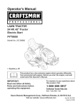
Attaching
the Battery
Cables
Thetractoris shippedwith an activatedsealedbattery,
Thepositivebatterycableis factoryconnected,The
negativecable mustbe connected,The positivebattery
terminalis markedPos,(+), The negativebattery
terminalis markedMeg,(-),
• This engineis certifiedto operateon unleaded
gasoline.Forbest results,fill thefuel tank with only
clean,fresh,unleadedgasolinewith a pumpsticker
octaneratingof 87 or higher.Incountriesusingthe
Researchmethod,it shouldbe 90 octaneminimum.
• Fromthe centernotchat thefront of the dashpanel,
lift thetractorhood and pivotforwardto open,
• Unleadedgasolineis recommendedbecauseit leaves
less combustionchamberdepositsand reduces
harmfulexhaustemissions.Leadedgasolineis not
recommendedand must notbe usedwhereexhaust
emissionsare regulated.
• Removethehex shoulderboltand wingnutfrom the
negative(black)cable,
Use extreme care when
handling gasoline.
Gasoline is extremely
flammable and the
WingNut
• Gasohol(up to 10%ethyl alcohol,90% unleaded
gasolineby volume)is an approvedfuel. Other
gasoline/alcoholblendsare notapproved.
vapors are explosive.
Never fuel machine
indoors or while the en-
• MethylTertiaryButyl Ether(MTBE)and unleaded
gasolineblends(up to a maximumof 15%MTBEby
volume)areapprovedfuels.Othergasoline/ether
blendsare notapproved.
gine is hot or running.
Extinguish cigarettes,
cigars, pipes, and other
sources of ignition.
Thegasolinetank is underthe rear fender,with the fuel
fill cap locatedin the centerof the rearfender. Thefuel
cap is tetheredto the tractorto preventits loss. Donot
attemptto removethe cap from thetractor.
Make sure the riding
mower's engine is off,
remove the ignition
key, and set the parking
brake before removing
the shipping brace.
The deck chute shipping
brace, used for shipping
purposesonly, must be
! removedand discarded
i beforeoperating your
i riding mower.
the engineis hotor running.Extinguish
cigarettes,cigars,pipes,and other
sourcesofignition.
NOTE: Purchasegasolinein small quantities.Do notuse
gasolineleft overfrom thepreviousseason,to minimize
gum depositsin the fuelsystem.
IMPORTANT:Makesure theignitionswitch is in the
"OFF"positionbeforeattachingthebatterycables.
WARNING
handlinggasoline.Gasolineis extremely
WARNING:Useextremecarewhen
flammable andthevaporsare explosive.
Neverfuel machineindoorsor while
IMPORTANT:Yourtractoris shippedwith motoroil in the
engine.However,you MUSTcheckthe oil levelbefore
operating.Refer to 'checkingthe oil level in the Maintaining your Tractor-Section6 of this manual.Be carefulnot
tooverfill.
Figure 1
• Pull the protectivecap, if present,off the negative
batteryterminal,Attachthe negativecable(heavy
blackwire) to the negativebatteryterminal(-) with
the boltand wing nut, See Figure1,
Mulching
Removal
• Thepositivecable(red cable)is securedto the
positivebatteryterminal(+)with a carriagebolt and
hexseresnut at the factory,Makecertain that the
rubberboot coversthe positivebatteryterminal,
Plug and Shipping
Brace
WARNING:Makesure the riding
mower'sengineis off, removethe
ignitionkey,and set the parkingbrake
beforeremovingthe shippingbrace.
NOTE:If the batteryis putinto serviceafter the date
shownon top of battery,chargethe batteryas instructed
on page 24 of this manualprior to operatingthe tractor.
8
,__
for packagingpurposes only,mustbe
WARNING:
Theshippingbrace,used
removedand
discardedbeforeoperating
yourridingmower.
A
WARNING:The mowingdeckis capable
of throwingobjects.Neveroperatethe
mowerdeckwithoutthe chutedeflector
in its downposition,evenwith the
mulchingplug installed.Failureto do so
could resultin seriouspersonalinjury
and/or propertydamage.
50" MowerDeck
Chute
Deflector
rLawn
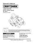
Removing Mulching Plug and Shipping
Brace From 46" Decks ONLY
•
Removethe wingnut and carriagebolt securingthe
mulchingplug in the deck dischargeopening,and pull
the mulchingplugfrom the deck,See Figure2,
ff46"Mower Deck
Vlulching Plug
WARNING
Carriage
The mowing deck is
capable of throwing
objects. Failure to operate the riding mower
without the chute
deflector in the down
Wing
Nut
operating position
could result in serious
\
/
personal injury and/or
property damage.
Figure 3
• Locatethe shippingbraceand tag, if present,
betweenthe chute deflectorand thecutting deck.
Holdingthe chutedeflectorfully upward,removethe
shippingbraceby graspingit and rotatingit. Lower
the chutedeflector.Referto Figure2.
Storethe mulchingplug for futureuse. Referto "Mulching"in Section4 : Operationfor instructionson installing
and usingthe mulchingfeature.
Tire Pressure
Figure 2
A
Locatethe shippingbraceand tag, if present,between
the chutedeflectorand the cuttingdeck, Holdingthe
chute deflectorfully upward,removethe shippingby
graspingit and rotatingit clockwise,Lowerthe chute
deflector,Referto Figure2,
Thetires on yourunit maybe over-inflatedfor shipping
purposes,Reducethe tire pressurebeforeoperating
the tractor.Recommendedoperatingtire pressureis
approximately10 p,s,iforthe reartires & 14 p,s,i,for the
fronttires, Checksidewallof tire for maximump,s,i,
Removing Mulching Plug and Shipping
Brace From 50" Decks ONLY
•
underanycircumstancesis 25
ARNING:Maximumtire pressure
psi.Equaltire pressureshouldbe
maintainedat all times.
Fullyraiseand hold the chutedeflector;thenslide
the mulchingplugout of the deck dischargeopening,
Lowerthe chutedeflector,
9
Maximumtire pressure
underanycircumstances
is 25 psi.The recommended tire pressure
shouldbe maintainedat
all times.
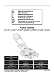
KNOW THE CONTROLS
Readthis owner'smanualand safetyrules beforeoperatingyourlawnmower,Comparethe figurebelowwith your
lawntractorto learnaboutthe locationand purposeof variouscontrolsand adjustments,Savethis manualfor future
reference.It is very importantto follow the instructionsand operatethe controlsproperly.
NOTE:
Any referencein this
manual to the R GHT
or LEFT side of the
tractor is observedfrom
operator's position.
Figure 4
A
SystemsIndicatorMonitor/Hour Meter
J
DeckLift Lever
B
ThrottleControlLever
K
Cup Holder
C
KeySwitchModule
L
SeatAdjustmentLever
D
ChokeControl Knob
M
FuelFillCap
E
PTO(BladeEngage)ControlSwitch
N
HydroTransmissionBypassRods
F
ParkingBrakeLever
0
FuelLevelWindow
G
H
12volt PowerOutlet
DrivePedal
P
Q
CargoNet
HoodLift Notch
I
BrakePedal
NOTE: Any referencein this manualto the RIGHTor LEFTsideof the tractoris observedfromoperator'sposition,
10
Throttle
Control
Lever
PTO (Blade Engage)
F PTO
The throttlecontrollevercontrols
Control
the speedof the engine,When
set in a givenposition,the throttle Fast
will maintaina uniformengine
Position
speed,
IMPORTANT:Whenoperating
the tractorwith the cuttingdeck
engaged,throttlecontrollever
mustalwaysbe in the FAST
Slow
(rabbit)position.
Position
Choke Control
Toengagethe electricPTOand
providepowerto the cuttingdeck,
pull outwardon the PTOcontrol
switchknob. Pushthe switchknob
inwardto disengagethe PTOand
stop thecuttingdeck.
NOTE: ThePTOControlSwitch
mustbe in the disengaged(OFF)
positionwhenstartingthe engine,
The chokecontrolknob is located
on the lowerleft sideof thedash
panel and is activatedbypulling
outward,Activatingthe chokecontrol closesthe choke
plateon the carburetorand aids in startingthe engine,
Key Switch Module
Switch
!
t
o
I
OFF
ONj
The keyswitch moduleis
usedto start and stop the
©
engine,It is also usedto
activatethe REVERSE
CAUTIONMODE.Insert
Brake Pedal
The brakepedalis locatedat the front of the right running key intothe key switch
moduleand
board and is usedfor quick stops,or settingthe parking
to the STARTposition,
brake,This pedal mustbe FULLYdepressedto activate
Releasethe key into
the safety interlockswitchwhenstartingthetractor.
the NORMALMOWING
Parking Brake Lever
positiononceenginehas
NOTE: The parkingbrakemustbe set if the operator
started.
leavesthe seat with the enginerunning;otherwisethe
enginewill automaticallyshut off,
h._,._
Tostop the engine,turn theignitionkey counterclockwise
• To set the parkingbrake,fully depress
to the STOPposition.
the brakepedaland pushthe bottom
of parkingbrakeleverinward, Seethe
imageto the rightfor parkingbrake
identification,Holdtheleverin while
disengagePTO,
moveshift
lever into
__b
ARNING:Neverleave
a running
removingyour foot fromthe brake
neutralposition,set parkingbrake,
pedal, Bothparkingbrakeleverand
stopengineand
removekey
machineunattended.
Alwaysto prevent
brakepedal will staydepressed,
unintendedstarting.
CHILDREN
AROUND
• To releasethe parkingbrake,depress
the brakepedal slightly,The parkingbrakeleverwill
then returnto its originalposition,
IMPORTANT:Prior tooperatingthe tractor,referto both
SafetyInterlockSwitcheson page 13 and StartingThe
Engineon page 14 of this manualfor detailedinstructions
IMPORTANT:Alwaysset the parkingbrakewhenleaving regardingthe IgnitionSwitchModuleand operatingthe
tractorin REVERSECAUTIONMODE.
the tractorunattended.
Drive Pedal
The drivepedal is locatedon the right sideof the tractor,
along the runningboard,Depressthe upper portionof
the drive pedalforwardto causethe tractorto travel
forward,Depressthe lowerportionof the drive 41.
pedal with the ball of your rightfoot (NOTyour
heel) to causethe tractorto travel in reverse,
Groundspeedis also controlledwith the drive
pedal,Thefurther forwardor rearwardthat the
pedal is pivoted,the fasterthe tractorwill travel.
The tractorwill slowand the pedalwill return
to its originalpositionwhenthe pedal is not
depressed,
__lb
the Start position whilethe engineis
ARNING:Nevermovethe
key into
running.Doingso
maycausedamageto
your engine'sstarter.
12V Power Outlet
The 12Vpoweroutlet is locatedbelowthe chokecontrol
on the left sideof the dashpanel.It is usedfor the
convenienceof pluggingin accessoriesthat requirea
powersourcewith a maximumloadof 5 arnpsat 12volts,
11
running machine
unattended.Always
parkingbrake,stop
engine andremove
]
MPORTANT
When operatingthe
tractorwith the cuttingdeck
engaged,throttlecontrol
lever mustalwaysbe in the
FAST (rabbit)position.
Alwaysset the parking
brake whenleavingthe
tractor unattended.
Priorto operatingthe
tractor, refertoboth Safety
InterlockSwitcheson page
13 and StartingThe Engine
on page 14of this manual
for detailedinstructions
g the KeySwitch
odu!eand operating
the tractor in REVERSE
CAUTION MODE.
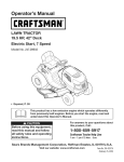
Systems Indicator Monitor/Hour
Oil PressureIndicatorLight
This warninglampindicateslow engineoil pressure.If
this indicatorilluminates,stop the tractorimmediately
and checkthe engineoil level.If the oil levelis within the
operatingrange,butthe light remainson, contactyour
CubCadetdealer.NOTE: Theoil pressureindicatormay
illuminatewhenthe keyswitch is turnedto an on position,
but shouldtum off whenthe engineis started.
Meter
Your tractor is equipped with a SystemsIndicator
Monitor as shown in Figure5. The monitor records the
accumulated hours of tractor operation, and displays
the informationon the LCDhour meterdisplay (tenths
of an hour- right most digit). The monitor also hasfour
indicator lights that showthe status of variousfunctions
of the tractor.
Battery
PTO Engaged Indicator Light
Oil
This indicatorilluminateswhenthe keyswitch is turned
to the "START"positionwhilethe PTOswitchis in the
"ENGAGED"position.Checkthis indicatorif the engine
will notcrank with the key switchin the "START"position.
Movethe PTOswitchto the "DISENGAGED"position.
LCDHourMeter
Brake Engaged Indicator
This indicatorilluminateswhenthe keyswitch is turned
to the "START"positionand the brakepedalis notfully
depressed.Checkthis indicatorif the enginewill not
crankwith the key switchin the "START"position.If
necessary,fully depressthe brakepedal...
123.4-
/
(®)
PTO
Seat Adjustment
ParkingBrake
Theseat adjustmentleveris on the left sideof the seat.
Use this leverto adjustthe seat forwardor rearwardto a
comfortableoperatingposition.See the MakingAdjustmentssectionlater in this manualfor instructions.
Figure 5
into the Start position
i may cause damage to
i your engine's starter.
Lever
The system indicator monitor features are as follows:
LCDHour MeterDisplay
Deck Lift Lever
The hour meter display is activated when the key
switch is turned to either the "NORMAL MOWING"or
Thedeck lift leveris locatedin the rightfenderand is
usedto changethe cuttingheightof the mowerdeck.The
cuttingheightsrangefrom 1-1/2"to 4"for the 46" mower
deck and 1-1/2"to 3-1/2"for the50" mowerdeck. Each
of the six indexnotchesrepresentan approximately1/2"
adjustmenttothe deck height.To use,graspthe lift lever
handleand pull slightlyupward(rearward)whilepivoting
the leverinwardand out of its indexnotch.Movethe lift
leveras necessaryto placein the notchbest suitedfor
yourapplication.
the "REVERSECAUTIONMODE"switch positions.
When the key switch is turned to an on position, the
battery indicator light briefly illuminatesand the battery
voltage is briefly displayed. The display then changes
to the accumulated hours.
NOTE: A record of the actual hours of operation
should be kept to assure maintenanceprocedures are
completed according to the schedule in this manual.
The IndicatorMonitorwill also remindthe operatorof
maintenanceintervalsfor changingthe engine oil. The
LCD will alternatelyflash the recordedhours, "CHG"and
"OIL"for five minutes,after every 50 hoursof recorded
operationelapse.The maintenanceinterval lasts for
two hours(from 50-52, 100-102,150-152,etc.). The
LCD will flash as describedfor five minutesevery time
the tractor'sengine is started duringthis maintenance
interval. Followthe oil changeintervalsprovidedin the
engine manualthis the Maintainingyour Tractorsection
of this Manual.
After changingthecuttingheightof the deck,you must
checkthe positionof the deckfront gaugewheelsand
rear rollers.Theyshouldbe approximately1/2-inch
above
the groundwhenthe tractoris on a smooth,flat surface
such as a driveway.Referto "AdjustingDeckGauge
Wheelsand Rollers"in the MakingAdjustmentssection
laterin this manual
Battery Indicator Light
Illuminateswhen theignitionswitchit turnedto an ON
positionand the engineis not started.
Fuel Fill Cap and Fuel Level Window
Cup Holder
Thetractor'scup holderis locatedon the fenderto the left
of the seat.
Thefuel fill cap is locatedin thecenterof the rearfender.
Pivotthe seat forwardto fully accessthe fuelfill cap and
fill the fueltank.
Illuminatesto indicatethebatteryvoltagehasdropped
below11.5(+0.5/-1.0)DC volts(the batteryvoltageis also Turnthe fill cap approximately1/4turn and pull upwardto
remove.Pushthe cap downwardon the fueltank fill neck
displayedon the hour meter).If this indicatorand display
comeon duringoperation,checkthe batteryand charging and turn 1/4turn clockwiseto tighten.
Thelevelof fuelin thefuel tank can be viewedthrough
systemfor possiblecausesand/or contactyourCub
Cadetdealer.
the fuellevelwindowin the rear hitchplate.
12
Cargo
Net
Convenientlylocatedon thetractor'sdashpanel,the
cargonet can be usedto storepersonalitemswhile
operatingthe lawntractor.
Hydro Transmission
Bypass
__b
Rods
Reverse
tobypasstheSafetyInterlockSwitchesin
anywaywillvoidyourtractor's
warranty.
ARNING:Tampering
withorattempting
Do notoperatethetractorif theinterlock
systemismalfunctioning.
Caution
Mode
The hydrotransmissionbypassrodsare locatedat the
back of the tractorabovethe rear hitch plate,When
engaged,these leversopena hydropumpbypass
valve in each transmissionwhich allowsthe tractorto
be pushedshort distancesmanually,See "Movingthe
TractorManually"laterin this section,
operatingthetractorin the REVERSE
CAUTION
MODE.Always
lookdownand
__b
ARNING:Useextreme
caution
while
behindbeforeand whilebacking.Do
notoperatethetractorwhenchildren
or othersarearound.Stopthetractor
immediatelyif someoneentersthearea.
Headlights
The REVERSECAUTIONMODE
The tractorheadlightsare turnedon whenevertheignition positionof the key switchmoduleallowsthetractorto be
switch is turnedto eitherof the run positions,
operatedin reversewith the blades(PTO)engaged,
IMPORTANT:Mowingin reverseis not recommended,
Safety Interlock
System
To usethe REVERSECAUTIONMODE:
The safetyinterlocksystemis designedfor safeoperation
IMPORTANT:
TheoperatorMUSTbeseatedinthetractorseat.
of the tractor.If this systemshouldevermalfunction,do
1. Start engineas instructedearlierin this manual
not operatethe tractor,immediatelycontactyourCub
section,
Cadetdealer.
2. Turnthe keyfrom the NORMALMOWING(Green)
° The safetyinterlocksystempreventsthe enginefrom
positionto the REVERSECAUTIONMODE(Yellow)
startingunlessthe parkingbrakeis engagedand the
positionof the key switchmodule.See Figure6.
PTOswitchis in the disengaged(OFF)position,
3. Depressthe REVERSEPUSHBUTTON(Orange,
• The safetyinterlocksystemwill automaticallyshut
off the engineif the operatorleavesthe seat before
engagingthe parkingbrake,
• The safetyinterlocksystemwill automaticallyshut off
the engineif theoperatorleavesthe tractor'sseatwith
the PTO(Blade Engage)switch engaged,regardless
of whetherthe parkingbrakeis engaged,
('_ndicator (FfNo ........
Light ___Push
• _'_
Butt°n/
_1
st°p.../II
• With the ignitionkey in the NORMALMOWING
position,theelectric PTOclutchwill automaticallyshut
off if the PTOswitch is in the engaged(ON) position
and the drivepedal is depressedfor Reversetravel,
Reverse_
- I
Ill Start |
_'__,,\
vos,uon /_(//
Position I
-__
ReverseCautionMode /
/
//
|
F
WARNING
Figure 6
TriangularButton)at the top, rightcornerof the key
switch module.The red indicatorlightat the top, left
cornerof the key switchmodulewill be ONwhile
activated,See Figure6.
AVOID SERIOUS INJURY OR DEATH
•
GO UP AND DOWN SLOPES, NOT ACROSS.
•
AVOID SUDDEN TURNS.
•
DO NOTOPERATE THE UNIT WHERE IT COULD SLIP OR TIE
•
IF MACHINE STOPS GOING UPHILL, STOP BLADE(S) AND
BACK DOWNHILL SLOWLY.
•
DO NOT MOW WHEN CHILDREN OR OTHERS ARE AROUND.
•
NEVER CARRY CHILDREN, EVEN WITH BLADES OFF.
•
LOOK DOWN AND BEHIND BEFORE AND WHILE BACKING.
•
KEEP SAFETY DEVICES (GUARDS, SHIELDS, AND
SWITCHES) IN PLACE AND WORKING.
•
REMOVE OBJECTS THAT COULD BE THROWN BY THE
BLADE(S).
•
KNOW LOCATION AND FUNCTION OF ALL CONTROLS.
•
BE SURE BLADE(S) AND ENGINE ARE STOPPED BEFORE
PLACING HANDS OR FEET NEAR BLADE(S).
•
BEFORE LEAVING OPERATOR'S POSITION, DISENGAGE
4. Onceactivated(indicatorlightON),thetractorcanbe
drivenin reversewith thecuttingblades(PTO)engaged,
5. Alwayslook downand behindbeforeand while
backingto make sureno childrenarearound,
6. After resumingforwardmotion,returnthe key to the
NORMALMOWINGposition,
IMPORTANT:The REVERSECAUTIONMODEwill
remainactivateduntil:
a. The key is placedin eitherthe NORMALMOWING
positionor STOPposition,
b. Theoperatorleavesthe seat,Followtheprevious
instructionsto re-activate.
BLADE(S), PLACETHE SHIFT LEVER IN NEUTRAL, ENGAGE
BRAKE LOCK, SHUT ENGINE OFF AND REMOVE KEY.
READ OPERATOR'S MANUAL
J
13
WARNING
Tamperingwith or
attempting to bypass
Switches in any way
theSafetylnterlock
will void your tracoperate the tractor if
t°r'sinterlock
the
warranty.
system
Do not
is malfunctioning.
Use extremecaution
whileoperating
the tractorin the
REVERSECAUTION
MODE.Alwayslook
down and behind
beforeand whilebacking. Do not operatethe
tractorwhen children
or others arearound.
Stopthe tractor immediatelyifsomeone
entersthe area.
Starting
the Engine
NOTE: Referto the TRACTORSET-UPon page 8 of this
manualfor gasolineand oil fill-upinstructions,
1, Insertthe tractorkeyinto the key switchmodule.
Stopping
___#
2, Disengagethe PTO(BladeEngage)lever/knob,
3, Engagethe tractor'sparkingbrake,
4, Pull thechoke controlknoboutwardintothe full choke
position(a warm enginemay not requirechoking),
5, Movethe throttlecontrolleverto midwaybetweenthe
SLOWand FASTpositions,
5, Turnthe ignitionkey clockwiseto the STARTposition,
After theengine starts,releasethe key,It will returnto
the NORMALMOWINGposition.
WARNING
If you strike a foreign
object, stop the
engine, disconnect
the spark plug
wire(s) anti ground
against the engine.
Thoroughly inspect
the machine foi any
damage. Repair dam-
the Engine
ject, stopthe engineand disconnect
the
spark plugwire(s).
Thoroughly
ARNING:
If you strikea
foreignobinspectthe machinefor anydamage.
Repairdamagebeforerestarting.
1, If the bladesare engaged,disengagethe PTO,
2, Movethe throttlecontrolleverto midwaybetweenthe
halfand fullthrottle.ThenturntheignitionkeycounterclockwisetotheOFFposition.
3, Removethekey from the ignitionswitchto prevent
unintendedstarting.
Driving The Tractor
IMPORTANT:Do not holdthe key in the STARTposition IMPORTANT:Avoidsuddenstarts,excessivespeedand
for longerthanten secondsat a time, Doingso may cause suddenstops.
damageto yourengine'selectricstarter.
° Brieflydepressthe brakepedalto releasethe
6, After theengine starts,graduallypushthechoke knob
parkingbrake. Movethe throttleleverintothe
fully inwardas the enginewarmsup,
FAST(rabbit)position,
NOTE: Do not usethe chokecontrolto enrichthe fuel
• Totravelforward:Slowlydepressthe upper portion
mixture,exceptas necessaryto start and warm up the
of the drivepedalforward untilthe desiredspeed
engine,
is achieved,See Figure7,
•
Totravelin reverse:Checkthat thearea behind is
clear,thenslowlydepressthe lowerportionof the
drivepedal with the ballof yourfoot (notyour heel)
untilthe desiredspeedisachieved,See Figure7,
°
Releasethe drive pedaland depressthe brake
pedalto stopthe tractor.
Brake Pedal
Drive Pedal
age before restarting.
Do notleavethe seat
of thetractorwithout
first placingthe PTO
leverin the disengaged(Blade Stop)
position,depressing
the brakepedaland
engagingthe parking
brake.If leavingthe
tractorunattended,
alsoturn the ignition
keyoff and remove
the key.
If leavingthe tractorunattended,alsoturn the
ignitionkeyoff and removethe key,
Do not mowon slopein excessof 15degrees(a rise
of approximately2-1/2feet every 10 feet),
Plan yourmowingpatternto avoiddischargeof
materialstowardroads,sidewalks,bystandersand
the like,Also, avoiddischargingmaterialagainst
a wallor obstructionwhich maycausedischarged
materialto ricochetback towardtheoperator.
k.
Reverse
Forward j
Figure 7
IMPORTANT:Do not usethe drivepedalto changethe
directionof travelwhenthe tractoris in motion.Always
bring thetractorto a completestop beforepivotingthe
drivepedalfrom forwardto reverseor vice versa,
__lb
14
the tractor without first placing the PTO
knob
in the disengaged(Blade
Stop)
ARNING:Donot
leavethe seat
of
position, depressing the brakepedal
and engaging the parking brake.If
leavingthe tractor unattended,also turn
the ignition key off and removethe key.
Steering the Tractor
Moving
Your i1000seriestractoris equippedwith an innovative
steeringdesignwhich is somewhatdifferentfrom that of
the traditionalsteeringwheeltype lawntractor.Turning
the steeringwheelnotonly turnsthe front wheels,but
also controlsthe drivelinkageof the two hydrotransmissions that drivethe tractor.Thisfeatureallowsyou to
vary the radiusof turns froma normalwideturn downto
a zeroturn. Somepracticemaybe requiredto become
accustomedto the steeringof yourtractor.Thesteering
worksas follows:
If for anyreasonthetractorwill notdriveor youwish to
movethe tractor,engagethetwo hydrotransmission
bypassrodsto manuallymovethe tractorshortdistances.
the Tractor Manually
IMPORTANT:Nevertow or dragthe tractorwiththe rear
wheelson the ground.Evenwith the bypassrodsengaged.
Doingso willdamagethe transmissions.
Toengagea bypassrod,pull the rod rearwardthroughthe
slot untilthe offset form the rod is outsidethe hitch plate.
Thenturnthe rod in eitherdirectionand releaseso that
the offsetis lockedagainstthe hitchplate. Engageboth
° The steeringwheelturns approximatelytwo turns stop bypassrodsto manuallymovethe tractor.See Figure8.
to stop.With the center positionbeingthe straight
ahead position.
BypassRods
_
/ Disengaged
° Minorturns of the steeringwheelfrom the center
position(up to approx.100) will turnonly thefront
i.
4'
/
axles and resultin widerturns.
°
Increasingtheturn of the steeringwheel (beyond10°)
resultsin increasinglytighterturns.As the steering
mechanismturnsthe front wheels,it alsochanges
the positionof the transmissiondrivelinkageto slow
downthe inner rearwheel in the turnand adjust the
speedof the outerwheelas necessaryto complete
the desiredturn. Turnthe steeringwheelback to the
center positionas the turn is completed.
OffsetFormLockedAgainst
WAR NING
To help avoid blade
contact or a thrown
J
NOTE: It is not necessarytoreleasethedrivepedal
whenmakinga turn. Thechangeto the transmission
linkageoccursregardlessof howfar the drivepedal is
depressed.Whenthesteeringwheelis straightened,the
tractorwillreturnto thespeedset by thedrivepedal.
° Turningthe steeringwheelfully to its stop in either
directionwill fully turnthe front wheels,reversethe
directionof the innerwheeland adjust theouter wheel
speedto executea zeroturn in the chosendirection.
Turnthe steeringwheelback to the centerpositionas
the turn is completed.
Figure 8
Todisengage,turnthe rod to align with the slot and
releasethe rod back throughthe hitch plate.
NOTE: Thetransmissionwill NOTengagewhenthe
hydrostaticbypassrod is pulledout. Returnthe rod to its
normalpositionpriorto operatingthetractor.
Mowing
WARNING: To helpavoidblade
contactor a thrownobjectinjury,keep
bystanders,helpers,childrenand
petsat least75 feet from the machine
whileit is in operation.Stop machineif
anyoneentersthe area.
NOTE: As the steeringwheelis turnedfurther toward
its stop, theeffortneededto tum thesteeringwheel
increases.
IMPORTANT:Makingtight or zeroturnson grasswill
greatly increasethe potentialfor defacementof the turf.
bystanders,helpers,
children and pets
at least 75 feet from
the machine while it
Thistractorisequippedwithoneof CubCadet'shighquality
cuttingdecks.Thefollowinginformation
willbe helpfulwhen
usingthecuttingdeckwithyourtractor.
Driving On Slopes
IMPORTANT:Referto theSLOPEGAUGEonpage3 tohelp
determineslopeswhereyoumayoperatethetractorsafely.
• Mowup and down slopes,neveracross.
• Watchfor holes,ruts, bumps,rocks,or otherhidden
objects. Uneventerraincouldoverturnthe machine.
Tallgrass can hideobstacles.
• Avoidturns whendrivingon a slope.If a turnmust
be made,turndownhillon the slope.Turninguphill
increasesthe possibilityof a tractorrollover.
• Avoidstoppingwhendriving up a slope.If it is necessary to stopwhiledriving up a slope,start up smoothly
and carefullyto reducethe possibilityof flippingthe
tractoroverbackward.
•
Do not mowat high groundspeed,especiallyif a
mulchkit or grass collectoris installed.
•
Forbestresultsitis recommended
thatthefirsttwolaps
becut withthedischargethrowntowardsthecenter.
Afterthefirsttwolaps,reversethedirectionto throw
thedischargeto theoutsideforthebalanceofcutting.
Thiswillgivea betterappearanceto thelawn.
•
Do notcut thegrass too short.Shortgrass invites
weedgrowthand yellowsquicklyin dryweather.
Mowingshouldalwaysbe donewith the engineat
full throttle.
•
IMPORTANT
Refertothe SLOPEGAUGE
on page3 tohelpdete_ine
slopeswhereyoumay
operatethetractorsafelyl
Never attemptto movethe
tractor manuallywithoutfirst
engagingthe reliefvalve.
Doing so rnaydamagethe
tractor,s transmission.
i_ :_ /i
_i iiiiiiiii_:
I
\i_,:
...........................................
j
15
*
.
.
Underheavierconditions
it maybe necessarytogo
backoverthecutareaa secondtimetogeta cleancut.
Do notattemptto mowheavy brushand weeds
and extremelytall grass.Yourtractoris designedto
mow lawns,not clearbrush.
Keepthebladessharpand replacethebladeswhen
worn.Referto CuttingBladeson page25 of this
manualfor properbladesharpeninginstructions.
IMPORTANT:Whenstoppingthe tractorforany reason
whileon a grass surface,always
* Placethe shiftleverin neutral,
.
Engagethe parkingbrake,
.
Shutengineoff and removethe key.
Doingso will minimizethe possibilityof havingyour lawn
"browned" byhot exhaustfrom yourtractor'srunning
engine.
NOTE: It is not necessaryto removethe chute deflector
to operatethe mowerwith the mulchplug installed.
• Themulchpluginstalledat thefactorywasremoved
earlierin the"Settingup yourLawnTractor"section.To
reinstallthemulchingplug,proceedasfollows:
Installing Mulching Plug on 46" Decks ONLY
• Raiseandholdthechutedeflectorin up position.
° Locatethe1/4inchholeinthetopofthemulchingplug.
Withtheholefacingupwardinsertthemulchingplugfully
intothedischargeopeningofthedeck.
° Alignthemulchingplugholewiththeholeinthetopof the
deckdischarge.Insertthecarriageboltthroughthetopof
thedeckandthemulchingplugand securewiththewing
nut.Referto Figure2 on page9
Installing Mulching Plug on 50" Decks ONLY
Mulching
in the down position
Failure to do so could
• Pivotthe chutedeflectorup to accessthe deck
dischargeopening.
Thei1000seriestractordecksareequippedwith a
mulchingkit. Themulchkit whichincorporatesspecial
° Locatetwo notchesin thechutedeflectorhingebracket
blades,alreadyon yourtractor,in a processof recirculating
abovethedeckdischargeopening.
grassclippingsrepeatedlybeneaththe cuttingdeck.The
° Insertthemulchplugintothedeckdischargeopening.
ultra-fineclippingsare thenforcedbackintothe lawnwhere
Makesurethetwotabsonthetopoftheplugarein the
theyact as a naturalfertilizer.
notchesofthehingebracket.Lightlytap on the plugwith
yourhand to assurethat the tabs fit snugly intothe
Observethefollowingpointsfor bestresultswhenmulching:
notches.
. Neverattemptto mulch if the lawnis damp.Wet grass
° Whileholdingthe mulchingplug in position,fully lower
tendsto stickto the undersideof the cuttingdeck
the chutedeflector.
preventingproper mulchingof the clippings.
result in serious
.
Do notattemptto mulch morethan 1/3the total height
of the grassor approximately1-1/2inches.Doingso
will causethe clippingsto clump up beneaththe deck
and not be mulchedeffectively.
.
Maintaina slowgroundspeedto allowthe grass
clippingsmoretimeto effectivelybe mulched.
Alwayspositionthrottlecontrolleverin theFAST(rabbit)
positionandallowit toremaintherewhilemowing.Failing
tokeeptheengineatfullthrottleplacesstrainon the
tractor'sengineanddoesnotallowthebladestoproperly
mulchgrass.
WARNING
The mowing deck is
capable of throwing
objects. Never operate
the mower deck without the chute deflector
personal injury and/or
property damage.
.
WARNING:The mowingdeck is capable
of throwing objects.Neveroperatethe
mowerdeckwithoutthe chutedeflector
in its downposition,evenwith the
mulchingplug installed.Failureto do so
could resultin seriouspersonalinjury
and/or propertydamage.
16
3. Oncethe desiredpositionis reached,releasethe seat
lever.Slidethe seat slightlyforeand aft as necessary
to engagethe seat leverinto one of the eightadjustanyadjustmentswhile the engineis
ment positionsin the indexplate. Makecertain the
running,exceptwherespecifiedin
seat is lockedin position.
___lb
ARNING: Neverattemptto makethe
operator'smanual.Disconnectspark
plug wire(s) beforeperformingany
Leveling the Deck
adjustments,repairsor maintenance.
NOTE:Checkthe tractor'stire pressurebeforeperforming any deck levelingadjustments.Referto Tires laterin
Steering and Transmission
Linkage
this sectionforfurther informationregardingtire pressure.
Thesteeringtie rod and drag links and the related
transmissionlinkageare set at the factoryand should
Side to Side Leveling
not requirefurther adjustment.Becauseof the complex
If thecuttingdeck appearsto be mowingunevenly,a side
adjustmentprocedure,the steeringand transmission
to sideadjustmentcan be performed.Adjustif necessary
linkageshouldonly be servicedor adjustedby a qualified
as follows:
mechanic.If youexperienceproblemswith steering,or
1. With thetractorparkedon a firm,levelsurface,move
with the hydrodrivetransmissions,contactyournearest
the deckto the midheightposition(thirdor fourth
CubCadetdealer to havethe tractorinspected.
notch)usingthe deck lift lever.Rotateboth bladesso
Making Adjustments
Adjusting
the Seat
WARNING: After adjusting the seat
__lb
sure that the seat adjustment lever is
r before driving the tractor, make
engaged in the seat index plate and
that the seat will not move. Do not
adjust the seat while the tractor is
being driven. Adjusting the seat while
the tractor is moving could cause the
operator to lose control of the tractor.
that they are perpendicularwith the tractorframe.
2. Measurethe distancefrom the outsideof the left blade
tip to the groundand the distancefrom theoutsideof
the rightbladetip to the ground.Bothmeasurements
takenshouldbe equal.If they'renot, notewhetherthe
left side of the deck is loweror higherand proceedto
the next step.
3. Workingfrom the left side of the tractor,loosen,but do
not remove,the hexcap screwon the left deck hanger
bracket.See Figure11.
50" Mower
1. Whilesittingin theseat,graspthe seatadjustment
leveron the left sideof the seat and pull it upwardto
disengagefrom the seat indexplate.See Figure9.
Deck Shown
2. Slidethe seattothedesiredposition.SeeFigure9.
i
Hex Cap Screw
Figure 10
4. Toeventhe deck turnthe adjustmentgear,located
immediatelybehindthe hexcap screw,clockwise
(rearward)to raisethe left side of the deck.Turnthe
gearcounter-clockwise(towardfront)to lowerthe left
sideof the deck. See Figure11.
5. Thedeck is properlyleveledwhenbothblade tip
measurements,as describedearlier,are equal.
6. Retightenthe hexcap screwon the left deck hanger
bracketwhenproperadjustmentis achieved.
17
WARNING
Neverattempt
to makeany
adjustments
while
theengineis
running,except
wherespecified
inthe operator's
manual.Stopthe
enginebefore
_erformingany
adjustments.
Beforeoperating
this machine,
makesurethe seat
isengaged inthe
seat stop.While
sittinginthe seat
beforeyoustart
the tractor,check
that the seatwill
not slidefore or
aft.
Front To Rear Leveling
Deck Gauge Wheel Adjustment
Thefront of the cuttingdeck is supportedby an adjustable frontdeck hanger rod. This rod can be adjusted
to set the front to rear pitchof the deck.The front of the
deck shouldbe between1/4-inchand 3/8-inch lowerthan
the rearof the deck.Adjust if necessaryas follows:
1. With thetractorparkedon a firm,levelsurface,move
thedeck to themid heightposition(thirdor fourth
notch)usingthe deck lift lever.Rotatethe blade
nearestthe dischargechute so that it is parallelwith
thetractorframe.
NOTE: The deck gaugewheelsare an anti-scalpfeature
of thedeck and are notdesignedto supportthe weightof
thecuttingdeck.
Thedeck gaugewheelsshouldneithercontactthe
ground,nor be highoff the ground,whenthe deck is
movedto the desiredheightsetting.If youchangeyour
cuttingheightduring the mowingseason,the gauge
wheelsshouldbe checkedand adjustedas necessary.
Adjustthegauge wheelsas follows:
2. Measurethe distancefrom the frontof the bladetip to • Placethe tractoron a smooth,flat surfaceand move
theground andthe rearof the blade tip to the ground.
thedeck to the desiredmowingheightusingthe deck
Thefront measurementtakenshouldbe between1/4"
lift lever.
and 3/8" lessthan the rear measurement.Determine
• Checkgaugewheels distancefrom theflat surface
theapproximatedistancenecessaryfor properadjustbelow.If the gaugewheelscontactthe ground,they
mentand proceed,if necessary,to the next step.
mustbe raised.If the gaugewheelsare higher than
3. Workingat the front of the tractor,loosenthe two hex
1/2" abovethe ground,they shouldbe lowered.
lock nuts at the frontof the deck hanger rod.Thread
• Removethe shoulderbolt securingone of thefront
the lock nuts awayfromthe hexnuts behindthem.
ball wheelsto the front indexbracket.Repositionthe
See Figure11.
ball wheelto align with theone of four indexholes
that placesthe wheel1/4"to 1/2"abovethe ground.
Securethe ball wheelto the indexbracketwith the
shoulderbolt. Notethe indexhole usedand secure
theother ball wheelin the same position.See Figure
12.
LockNut
FrontIndex
Bracket
adjustments.
of Deck
_
Raise Front
of Deck
j
Figure 11
4. Usinga wrench,turn the innerhex nutsclockwise
to raisethe frontof the deck,or counterclockwiseto
lowerthe front of the deck.Adjustthe hexnuts evenly
so that the deck hangerrod is at the frontof bothslots
in the hangerbracketon the frontof thedeck. See
Figure11.
5. Retightenthe two hexlock nuts whenproperly
adjusted.
18
Figure 12
Shoulder
Bolt
50" DeckONLY
Deck Rear Roller Adjustment
The50" deck rollerassemblyindexbrackethasfive
adjustmentpositionsholes,
The rear rollerson the mowerdeck are notdesignedto
carry the weightof the deck,The rear rollersshouldbe
adjustedto approximately1/4"to 1/2"abovethe ground
whenthe deck is movedto the desiredcutting height,
Placethe tractoron a smooth,flat surface,movethe deck
to the desiredcuttingheight,and checkthe heightof the
rear rollers,If contactingthe ground,or above1/2" from
the ground,adjust the rear rollersas follows:
• Whilesupportingthe rollerassembly,removeclick pin
and withdrawthe clevispin from boththe left and right
roller indexbrackets,See Figure14,
Index Brkt.
Click Pin
46" Deck ONLY
ustments
The 46"deck rollerassemblyindexbrackethasthree
adjustmentpositionsusingeitherthe bottomtwo holes,
middletwo holes, or top two holes.
• Supportthe rollerassemblyand removethe two self
tappingscrewsfrom boththe left and rightroller index
brackets,
•
Positionthe rollerassemblyso that the rollersare approximately1/4"to 1/2" abovethe flat surfacebelow,
Align the nearesttwo indexbracketholeswith holesin
the deck mountingbrackets,See Figure13,
WARNING
Clevis Pin
• Securethe rollerassemblywith thefour self tapping
screws.See Figure13.
NOTE: Theself tappingscrewsshouldbe in the
correspondingholesof boththe left and rightrollerindex
brackets,
Figure 14
• Positionthe rollerassemblyso that the rollersare approximately1/4"to 1/2"abovethe flat surfacebelow.
• Alignthe nearestindexbracketholeswith the holes
in the deck mountingbrackets.Insertthe clevispins
throughthe deck bracketsand the indexbracketsand
securewith the click pins.See Figure14.
Roller Index Brkt.
0
NOTE:The clevispinsshouldbe in the corresponding
holesof boththe left and right rollerindexbrackets.
Self Tapping
Screws
Figure 13
19
Neverattempt
to makeany
adjustments
while
the engineis
running,except
wherespecified
inthe operator's
manual.Stopthe
enginebefore
performing
any
adjustments.
Maintaining
Your Lawn Tractor
RecommendedViscosityGrades
WARNING:Beforeperformingany
maintenanceprocedures,inspections,
or repairs,disengagePTO,set parking
brake,stop engineand removekeyto
preventunintendedstarting.
nln
Checking Engine Oil Level
Checkengineoil levelbeforeeachuse as follows:
• Placethetractoron a flat surfaceand stopthe
engine.Allowthe engineto cool long enoughfor the
oil to draininto theengine sump,
• Cleanthearea aroundthe oil dipstick/fillcap,
unscrewthedipstick/fillcap from the fill tubeon the
engine.Removethedipstick and wipethe oil off,
Reinsertthe dipstickinto thetube and rest the cap
on the tube. Do notscrewthe caponto thetube. See
Figure15.
f
]
Oil FillTube
i
Before performing
:__o
0o 20o 40o 60o 80o 100o
(°C)-30 o -20o -10° 0° 10° 20o 30o 40o
IMPORTANT:Neveroperatethe enginewith theoil level
belowthe"ADD"or "L"mark,or abovethe"FULL"or "F"
mark,on the dipstick,
Changing
Engine Oil & Filter
Changethe engineoil and oil filter after every 100hours
of operation,
• Pop openthe protectivecap on the end of the oil
drain valveto exposethedrain port. Pushthe oil drain
hose(packedwith this manual)onto theoil drain port.
Routethe oppositeend of the hoseintoan appropriate
oil collectioncontainerwith a capacitygreatenoughto
collectthe usedoil.
i any maintenanceor
i repairs, disengage
PTO, move shift
lever into neutral
position, set parking
brake, stop engine
and remove key to
• Removetheoil fill cap/dipstickfromthe oil fill tube.
Pushthedrain valve in slightlyand turn counterclockwise untilit stop,thenpull the valvefully outwardto
open thevalve and drainthe oil. Referto Figure15.
Oil DrainValve
i prevent unintended
starting.
• After theoil hasfinisheddraining,pushtheoil drain
valveback in, rotateit clockwiseto lock the valve
closed.Removethe drain hoseand re-capthe end of
the oil drain valveto keepdebrisfrom entering.
Before lubricating,
I repairing,or
i inspecting, always
I
disengage PTO, set
parking brake, stop
2engine and remove
key to prevent
unintended starting.
(°F)-20o
• Runthe enginefor a short time to warmthe engine
oil, Theoil willflow morefreely and carry awaymore
impurities,
• Locatethe oil drain valveon the rightsideof the
engine,beneaththe startermotor.Referto Figure15.
Dipstick/OilFillCap
WARNING
ann
.)
v
Fromthe left sideof the engine,removetheoil filter
usingan automotivetype oil filterwrench (See Figure
17).Wipethe filter adapterwith a cleancloth.
Figure 15
Pull thedipstick outand checkthe oil level.The oil
levelshouldbe up to, but notover,the "FULL"of "F'
markon the dipstick.See Figure16.
Full Mark
.-I
.-I
..I.
1
Ol_erating
ange
1
o
Figure 16
If the levelis low,add oil of the propertype (See
followingViscosityChart),up to the "FULl_"or "F"
markon the dipstick.Alwayscheckthe levelwith the
dipstickbeforeaddingmoreoil. Donot overfill the
crankcase.
20
Figure 17
Placethe newoil filter in a shallowpan withopen end
up. Pournewoil, of the propertype, intothe center
threadedhole.Stop pouringwhenthe oil reachesthe
bottomof the threads.Allowa few minutesfor the oil
to be absorbedby thefilter material.
3. Washthe precleanerin warmwaterwith detergent.
Rinsethe precleanerthoroughlyuntilall tracesof
detergentare eliminated.Squeezeout excesswater
Applya thin coat or newoil on the rubbergasketof the
(do not wring).Allowthe precleanerto air dry.
newoil filter.
4. Saturatethe precleanerwith newengineoil.
• Installthe newoil filter on the filter adapter.Hand
Squeezeoutall excessoil.
tighten untilthe filter gasketcontactsthe adapter,then
5. Reinstallthe precleaneroverthe paperelementand
tightenthe filter an additional3/4-1 turn.
securewith the latch.
• Refillthe enginewith the propertype oil. Theengine
oil capacityis approximately1.7-1.9quarts (1.6-1.8L). NOTE: Reinstallthe air filter elernent/precleanerif
removed.
Air Cleaner
6. Pivotthe latch overthefilter assemblyand pressthe
latchdownwardto rehook.See Figure18.
Checkthe air cleanerbeforeeach use.Checkfor a
buildupof dirt of debrisaroundthe air cleanersystem.
Keepthearea clean. Keepthis area clean.Also check
for looseor damagedcomponents.Replaceall bentor
damagedair cleanercomponents.
IMPORTANT:Makecertainthe latch is securedin the
lockedposition.Failureto properlyhookthe latchwill
allowunfilteredair intothe enginecausingdamageto
the engine.
7. Closethe accessdoor
looseor damagedair cleanercompoARNING:Operatingthe
enginewith
nentscould
allowunfilteredair
intothe
__lb
Servicing
enginecausingprematurewearand
failure.
Servicing
the Precleaner
Washand reoilthe precleanerevery25 hoursof
operation(moreoften underextremelydusty or dirty
conditions).Replacethe precleanerannuallyor every
100hours.
1. Open the dooron the blowerhousingto accessthe air
cleanerelementand precleaner.
2. Unhookthe latch and removethe precleanerfrom the
air filterelement.See Figure18.
AccessDoor
Latch
Filter
Element
Paper Element
Checkthe paperelementevery 50 hoursof operation
(moreoften if operatedunderextremelydusty or dirty
conditions).Cleanor replacethe elementas necessary.
Replacethe air cleanerelementannually,or every 100
hoursof operation.
after every100 hours
of operation,Failure
• Openthe accessdoor,unhookthe latch,and remove
the air filter assemblyas describedin the previous
sub-section.
premature wear or
failure of the engine,
• Removethe precleanerfromthe filter element.
• Gentlytap the paperelementto dislodgedirt. Do
notwash the paperelementor usepressurizedair,
as this will damagethe element.Replacea dirty,
bent,or damagedelement.Do notuse if the sealing
surfacesare bentor damaged.
• Cleantheair cleanerbaseand check its condition.
• Reinstallthe precleaneroverthe paperair cleaner
elementand installon base.Securewith the latch
and closethe accessdoor.
Spark Plug(s)
Every 100hoursof operation,removethe sparkplugs.
Checkthere conditionand resetthe gap,or replacewith
newplugs.
• Beforeremovingthe sparkplug,cleanthe area
aroundthe baseof the plugtoe keepdirt and debris
outof theengine.
Precleaner
Figure 18
NOTE: Theair filterelernent/precleanerassemblycan
be removedand the precleanerthen removedfromthe
filter element.Makesurethe baseand the sealingarea is
clean beforereinstallingthe air filter elernent/precleaner
assembly.
WARNING
• Removethe plugand checkits condition.Replace
the plug if wornor reuseis questionable.
NOTE: Donot cleanthe sparkplug in a machineusing
abrasivegrit. Somegrit could remainin the spark
plug and entertheengine causingextensivewear and
damage.
21
Operating the engine with loose or
damaged air cleaner
components could allow unfiltered air into
the engine causing
premature wear and
failure.
Checkthegap usinga wire feelergauge,Adjustthe
gap to ,030in, (0,76ram)by carefullybendingthe
groundelectrode,See Figure19,
Steering Maintenance
Steering
Lubrication
Thesteeringarms,pivot shafts,and axles must be
lubricatedif everthe steeringeffort increases,or after
every25 hourof operation.Lubricateusinga pressure
greasegun and CubCadet251HEP grease,or an
equivalentNo. 2 multipurposelithium grease.
Electrode
° Applygreasethroughthe lubefitting on the RH and
LH steeringarms whichare locatedat rearwardend of
the two steeringdrag links.See Figure20.
.030 in. (0.70-0.80ram)
J
Steering
.....................
GearCover
Figure 19
SteeringArm
LubeFitting
• Reinstallthe sparkplug into thecylinderhead,
Torquethe sparkplug to 18-22ft, Ibs, (24,429.8N.m).
Engine Cooling
Thissymbolpoints
oUtimportantsafety
instructions
which,if
not followed,
could
!
endangerthe personal
safety and/or property
of yourself and others.
Read and follow all
instructions in this manua before attempt ng to
operate this machine.
FailuretO comply with
these instructions
result in personal injury.
when yousee this
symbol
HEED ITS WARNING
Toensurepropercooling, makesurethe grass screen,
coolingfins, and otherexternalsurfacesof theengine
are kept cleanat all times,
Every 100hoursof operation(moreoften under
extremelydusty,dirty conditions),removethe blower
housingand othercoolingshrouds,Cleanthe cooling
fins and externalsurfacesas necessary,Makesurethe
coolingshroudsare properlyreinstalled,
AxlePivotBar
LubeFittings
Carburetor
Figure 20
In compliancewith governmentemissionstandards,the
carburetoris calibratedto deliverthecorrectfuel-to-air
mixtureto the engine underall operatingconditions.
Thehigh speedmixtureis set at the factoryand cannot
be adjusted.
Cleaning
of
tOpersons who read,
understand
and follow the warnings
Gears
Oncea year,or if a tight spot is experiencedwhenturning
the steeringwheel, removethe steeringgear coveron
• Makesurethe fuel tank is filledwith clean, fresh
eachend of the pivot bar and cleanthe two steering
gasoline.Makesurethefuel tank vent is not blocked. gears,
• Makesurethe in-line fuelfilter is cleanand unob• Frombeneaththe coverbase plateon eachend of the
structed.Replacethefilter if necessary.
pivot bar,removethe threehex screwssecuringthe
steeringgearcover.Removethe coversand cleanthe
• Makesurethe air cleanerelementis cleanand all air
gears, It is not necessaryto lubricatethe gears,Refer
cleanerelementcomponentsare fastenedsecurely.
to Figure20,
If after checkingthe aboveitemsthe engineis hard to
• Insertthe tabof the LHsteeringgear coverintothe
start, runsroughly,stalls,or lackspower,contactyour
squarehole in the LH baseplate,positionthe cover,
CubCadetdealer to havethecarburetorand fuel pump
and securewith the threehexscrews,Donot over
inspected.
tighten,Repeatto install thecover on the RH side,
Pivot Bar adjustment
Changethe fuel linefilter after every 100 hoursof
operation,Thefuel filter is locatedon the left sideof the
enginein thefuel line, Notethe orientationof the filter to
installthe newfilter correctly,
i
and instructions
in
this manual
Steering
If enginetroublesare experiencedthat appearto be fuel
systemrelated,checkthe followingareas:
Fuel Line
Restrict the use
this power machine
Locatethe lube fittingsfor the pivot shaftand axleon
the frontof one end of the axlepivot bar.Applygrease
throughthe two lube fittings,then repeatto lubricate
the otherend of the pivotbar, See Figure20,
° Placea containerbelowthefilter to catch anyspilled
gasolineand carefullyclampthe fuel lines,
° Loosenthe hoseclampsto removeand replacethe
filter,
22
If excessiveplayis experiencedin the steeringwheel,
checkthe pivotbar for forward/rearwardmovement,
1, Raisethe front of the tractorand set it on jack stands,
so the frontwheelsare suspendedabovethe ground,
2, Graspingthe endsof the pivotbar,attemptto move
eachend of the axle forwardand rearwardtocheck
for sideplay,Thereshouldbe minimalor no side play,
,
If there is no side play,lowerthetractorto the ground
and havethe steeringlinkageinspectedby youCub
Cadetdealer.If thereis side play,tightenthe pivotbar
as follows:
• Supportthe pivot bar,then removethe hex lock
nutssecuringthe two shoulderbolts that pass
throughthe pivotbar bracket,the pivotbar,and
frame,Referto Figure20,
• Slidea half inchflat washer,with a maximumthichnessof ,030inch,onto eachshoulderbolt, Reinstall
the sholderboltsw/washersand fastenwith the two
hexlock nuts,
• Graduallyand evenlytightenthe hexlock nutwhile
continuingto checktheforward/rearwardmovementof the pivot bar.Tightenthe lock nuts until
minimumplay,withoutbindingthe pivotbar'sup
and downmovement,is achieved,
Deck Wash System
TM
Yourtractor'sdeck is equippedwith waternozzleson its
surfaceas partof its deck washsystem,
Use the DeckWashSystemTM to rinsegrassclippings
fromthe deck'sundersideand preventthe buildup
of corrosivechemicals,Completethe followingsteps
AFTEREACHMOWING:
1, Drivethe tractorto a level,clear spoton yourlawn,
nearenoughto a water sillcock(spigot)for your
gardenhoseto reach,
IMPORTANT:Makecertainthe tractor'sdischargechute
is directedAWAYfrom yourhouse,garage,parkedcars,
etc,
2, Disengagethe PTO(Blade Engage),set the parking
brake,and stop theengine,
3, Threadthe nozzleadapter(packagedwith your
tractor'sOperator'sManual)ontothe end of your
gardenhose,
Lubrication
Front Wheel Bearings
Lubricatethefront wheelbearingswith Cub Cadet251H
EPgreaseafter every25 hoursofoperation,Thelube
fittings are locatedin the rimhub insideeachfront wheel,
4, Pull back thelock collar ofthe nozzleadapterand
pushthe adapterontothe deck wash nozzleat the
left end of the mowerdeck, Releasethe lock collar
to lock the adapteron the nozzle,See Figure21,
Deck Spindles
46" DeckShown
Lubricatethedeck spindlewith Cub Cadet251HEP
greaseafter every 10hoursof operation,
° The deck spindlelube fittings are in the spindlehousings, and can onlybe accessedfrom the undersideof
the deck, Usea pressuregreasegun to lubricatethe
spindles,
• 50" Deck ONLY- Lubricatethe deck idler bracket
every 10 hoursof operation,The idler bracketlube
fitting is in theshoulderboltthat securesthe bracket
to the deck,
Nozzle
pter
Pivot Points & Linkage
Lubricateall the pivot pointson the drive system,parking
brakeand lift linkageat leastoncea seasonwith light oil,
Figure 21
Rear Wheels
The rear wheelsshouldbe removedfrom the axlesonce
a season,Lubricatethe axlesand the rimswellwith an
all-purposegreasebeforere-installingthem,
Cleaning the Tractor
Nozzle
and Deck
Any fuelor oil spilledon the machineshouldbe wipedoff
promptly,DoNOTallowdebristo accumulatearoundthe
deck pulleysor anyotherpart of the machine,
Periodicallyremovethe beltcoversand removeany
accumulatedgrass clippingsfromaroundthe spindle
pulleysand the deck belt,
5, Turnthe wateron,
6, Whilesittingin theoperator'spositionon the tractor,
re-starttheengine and placethethrottle leverin the
FAST(rabbit)position,
7. Movethe tractor'sPTO(BladeEngage)intothe
ON position,Remain in the operator's position
with thecutting deckengagedfor a minimumof two
minutes,allowingthe undersideof the cuttingdeck
to thoroughlyrinse,
8, Movethe tractor'sPTO(BladeEngage)intothe OFF
position,Turnthe ignitionkey to the STOPposition
to turnthe tractor'sengineoff,
IMPORTANT:The use of a pressurewasherto cleanyour
9, Pull back thelock collar ofthe nozzleadapterto
tractoris NOTrecommended,It maycausedamageto
disconnectthe adapterfrom the nozzle,
electricalcomponents,spindles,pulleys,bearingsor the
10,Repeatthe previoussteps4 thru9 to cleanthe deck
engine,
usingthe nozzleat theother end of thedeck,
23
WARNING
This symbol points
out important safety
instructionswhich, if
not followed, could
endangerthe personal
safety and/or property
of yourself and others.
Read and follow all
instructions in this manual before attemptingto
operate this machine.
Failureto comply with
these instructions may
result in personal injury.
When you see this
symbol.
HEED ITS WARNING
Your
Responsibility
Restrict the use
of this power machine
to persons who read,
understand
and follow the warnings
and instructions
in this manual
Tires
_
2. Connectthe otherjumpercableto the negative
terminalof the good battery,thento the frame of the
unit with the dead battery.
muminflationpressureshownon the
ARNING:Neverexceedthe
maxisidewallof
tire.
The recommendedoperatingtire pressureis:
• Approximately10 psifor the rear tires
__b
° Approximately14psi for the fronttires
Cleaning
couldcausesparking,and thegas in eiARNING:Failureto usethis procedure
ther battery couldexplode.
the Battery
Cleanthe batteryby removingit fromthe tractorand
IMPORTANT:Referto the tire sidewallforexacttire
washingwith a bakingsodaand watersolution,If necesmanufacturer'srecommendedor maximumpsi. Do not
sary,scrapethe batteryterminalswith a wire brushto
overinflate,Uneventire pressurecouldcausethe cutting
removedeposits,Coat terminalsand exposedwiringwith
deck to mow unevenly,
greaseor petroleumjelly to preventcorrosion,
Battery
Battery
Thebatteryis sealedand is maintenance-free,
Acid
levelscannotbe checked,
• Alwayskeepthe batterycables and terminalsclean
and freeof corrosivebuild-up,
WARNING
Batteries giveoff an
explosive gas while
charging.Charge
i the battery in a well
ventilated area and
i keep away from an
open flame or pilot
light as on a water
i heater, space heater,
furnace, clothes dryer
I or other gas appli-
Iances.
i Be sure to shut the
engineoff,remove
ignition key, and
disconnect the
spark plugwire(s) to
i prevent unintended
i starting before
removingthe mower
deck.
Failures
Somecommoncausesfor batteryfailureare:
• incorrectinitialactivation
• undercharging
• overcharging
• corrodedconnections
• After cleaningthe batteryand terminals,apply a light
coat of petroleumjelly or greaseto bothterminals.
• Alwayskeepthe rubberboot positionedoverthe
positiveterminalto preventshorting.
° freezing
IMPORTANT:If removingthebatteryfor anyreason,
disconnectthe NEGATIVE
(Black)wirefromit's terminal
FIRST,followedby thePOSITIVE(Red)wire,When
re-installingthe battery,alwaysconnectthe POSITIVE
(Red)wire its terminalfirst, followedby the NEGATIVE
(Black)wire, Becertainthat thewiresare connectedto
thecorrectterminals;reversingthem couldchangethe
polarityand resultin damageto yourengine'salternating
system.
Toremovethe cuttingdeck, proceedas follows:
Charging
If the tractorhas not beenput into usefor an extended
periodof time,chargethe batterywith an automotivetype 12-voltchargerfor a minimumof one hour at six
amps.
WARNING: Batteriesgive off an explosivegaswhile charging.Charge
battery in a well ventilatedareaand
keep awayfrom an open flame or pilot
light as on a water heater,spaceheater, furnace, clothesdryeror othergas
These failures are NOT covered by your tractor's
warranty.
Cutting Deck Removal
1, Disengagethe PTO(BladeEngage)and engagethe
parkingbrake,
2, Placethedeck gaugewheels in their highestsetting
(lowestdeck setting),
3. Lowerthe deck by movingthedeck lift leverintothe
bottomnotchon the rightfender.
4. Lookingat the cuttingdeck fromthe left sideof the
tractor,locate thedeck supportpin on the rearleft
sideof thedeck, See Figure22,
50" Mower
Deck Shown
appliances.
Jump Starting
,_
installingthe battery,follow theseinWARNING:
removingor
structionstoWhen
preventthe
screwdriver
from shortingagainsttheframe.
Figure 22
5. Pull thedeck supportpin outwardto releasethe deck
from thedeck lift arm.
IMPORTANT:Neverjump yourtractor'sdead battery
with the batteryof a runningvehicle,
6. Moveto the rightside of the tractorand pull the deck
supportpin outwardto releasethe deck from the RH
lift arm.
1, Connectend of one jumpercableto the positive
terminalof the good battery,thenthe otherend to
the positiveterminalof the deadbattery,
24
7. Movethedeck lift leverintothe top notchon the right
fenderto raisedeck lift arms up and out of the way.
8. Carefullyslidethe cuttingdeck forwardand remove
the deck belt fromaroundthe tractor'sPTOpulleyon
the bottomof the engine.
9. Continueto roll the deck towardthefront of the tractor
until the frontdeck hanger rod canbe removedfrom
the slotsof the hangerbracketat thefront of the deck.
10.Whileholdingthe front deck hangerrod upwarduntil
it clearsthe hangerbracketon the front of the deck,
carefullyslidethedeck out from the rightside of the
tractor.
° Toproperlysharpenthe cuttingblades,remove
equalamountsof metalfrom bothendsof the blades
alongthe cuttingedges,parallelto the trailingedge,
at a 25oto 30oangle.
IMPORTANT:If the cuttingedgeof theblade has
alreadybeen sharpenedto within 1 5/8" from the edge,
or if anymetal separationis present,replacethe blades
with newones. See Figure24.
Cutting Blades
A
• Usea wrenchto loosenthehexflangenutthatsecures
thebladetothe spindle.Holdingthebladeontothestar
hubof thespindle,or usinga secondwrenchto hold
thenutatthetopof thespindle,securethe spindleand
removetheflangenutand cuttingblade.Repeatto
removetheotherthreeblades.
WARNING:Be sureto shut the engine
off, removeignition key,disconnect
thespark plugwire(s) to preventunintendedstartingbeforeremovingthe
cuttingblade(s)for sharpeningor replacement.Protectyour handsbyusing
heavyglovesor a ragto graspthe cutting blade.
WARNING
Use caution when
WARNING:Periodicallyinspect the
bladespindlesfor cracksor damage,
especiallyif you strikea foreign object.
Replaceimmediatelyif damaged.
WindWing
The bladesmaybe removedas follows.
•
your hands.
Removethe deck from beneaththetractor,(referto
CuttingDeck Removalon page 24) thengently flip the
deck overto exposeits underside.
A block of woodmay be placedbetweenthe deck
housingand the cuttingedge of the blade to help in
breakingloosethe hex nut securingthe blade.See
Figure23.
('I"Hex FlangeNut
Figure 24
• It is importantthat eachcuttingblade edge be
groundequallyto maintainproperblade balance.
A poorlybalancedbladewill causeexcessive
vibrationand maycausedamageto thetractorand
result in personalinjury.The bladecan be tested
by balancingit on a roundshaftscrewdriver.Grind
metalfrom the heavyside untilit balancesevenly.
WoodBlock
• Whenreplacingtheblade,be sureto installthe
bladewith the side of the blademarked"Bottom" (or
with a part numberstampedin it) facingthe ground
whenthe moweris in the operatingposition.
IMPORTANT:Usea torquewrenchto tighten the blade
spindlehexflangenutto between70 foot-poundsand
90 foot-pounds.
SpindleAssembly
k,,..
handling the cutting
blades. The sharpened edges could
cause severe cuts to
j
Figure 23
25
Shut tractor engine
off, remove ignition
key, and disconnect
the spark plug wire(s)
before proceeding
with job. Protect
your hands by using
heavy gloves or a rag
to graspthe cutting
blade
Fuses
• Removethespindlecoversby removingthe self-tapping screwsthat fastenthem to the deck, Referto
• A 20 ampfuse is installedin yourtractor'swiring
Figure25.
harnessto protectthe tractor'selectricalsystemfrom
damagecausedby excessiveamperage.
• 46"MowerDeckONLY- Removethe old beltfrom
the deck,Installthe newbeltaround thespindleand
• If the electricalsystemdoes notfunction,or your
idler pulleysas shownin Figure26.
tractor'senginewill not crank,firstcheckto be
• 50" MowerDeckONLY
certainthat the fuse has not blown.
Thefuse can be foundinsideof the dash panel
behindthe batterytray, You may needto removethe
batteryto gain accessto the fuse.
1.
Loosenthe hex screwfasteningthe idler pulley
to the idler armas necessaryto slidethe belt
from betweenthe idler pulleyand idler arm. See
Figure25.
A fiveamp fuse canalso be foundinsidethe dash
panel.This fuse is forthe 12volt poweroutlet.
]1
Spindle Cover
Alwaysuse a fusewith the same amperagecapacity
for replacement.
dler Pulley
Changing TransmissionDrive Belt
IMPORTANT
IMPORTANT: Always
use a fuse with the
same amperage capacity for replacement.
NOTE: Severalcomponentsmustbe removed,including transmissionsteeringlinkagewhichwill haveto be
readjusted,in orderto changethetractor'stransmission
drivebelt,ContactyourCubCadetdealerto haveyour
transmissiondrivebeltreplaced,
Hydrostatic Transmission
Figure 25
Keepthe area aroundthe transmissioncoolingfan
freeof grass and debrisat all times, The hydrostatic
transmissionis sealedat thefactory and is maintenance
free,The fluid levelcannot be checkedand cannotbe
changed,
Changing
the Deck Belt
WARNING: Besure to shut the engine
off, remove ignition key,disconnect
the spark plug wire(s) to prevent
unintended starting before removing
the belt(s).
WARNING:Avoidthe possibility of
a pinching injury. Do not place your
fingers on the idlerspringor between
the belt and a pulleywhileremoving
the belt.
2.
Placethe newbelt betweenthe idler pulleyand
idler arm.The backsideof the 'V' belt shouldbe
againstthe idler pulley,Tightenthe hexscrewto
securethe idler pulley,
3.
Routethe deck beltaroundthe spindlepulleys
and idler pulleysas shownin Figure27.
Reinstallthe spindlecoverson the deck usingthe
self-tappingscrews.Do not overtightenthe screws.
Reinstalling
the Cutting Deck
Thereare two methodsfor reinstallingthe mowerdeck on
the tractor,One methodinvolvesrotatingthe deckidler
armto relieveenoughbelttensionto allowthe belt to be
placedin eitherthe PTOpulleyor the deck idler pulley,
Becausethat methodis difficult,we recommendusing
the secondmethodof rollingthe beltonto the PTOpulley.
Installthe cuttingdeck as follows:
All belts on yourtractorare subjectto wearand should
be replacedif anysigns of wearare present,
• Fromthe rightside of the tractor,slidethedeck under
the tractorand align the read deck hangerbracket
with the deck lift arms.
IMPORTANT:Do notuse substitutebelts.TheV-belt
foundon yourtractoris speciallydesignedfor optimal
performanceand servicelifefor yourdeck application.
Use onlyOEMoriginal replacementbelts.
Slide thedeck forwardand placethe deck front
hangerrod intothe slotsof the deckfront hanger
bracket.Then slidethe deck rearwardsothat the
Tochangeor replacethedeck belt on your tractor,
proceedas follows:
hangerrod is at the front of the slots.
Usingthe deck lift lever,lowerthe deck lift arms.From
eithersideof the tractor,pull the supportpin in the
deck rear hangerbracketoutward,alignthe deck lift
armhole with the deck supportpin and releasethe pin
so that it goesthroughthe deck lift arm. Repeaton the
othersideof the tractorto securethe deck.
• Removethedeck from beneaththe tractor(referto
CuttingDeckRemovalon page24)
26
• After first makingsurethe deck beltis properly
engagedin all of the deck pulleys,routethe deck belt
forwardthroughthe centerof the front deck hanger
rod and towardthe PTOpulleyon the bottomof the
engine,
•
Usingthedeck lift handle,raisethedeck to the
positionthat gives youthe most horizontalrunof the
belt betweenthe deck pulleysand the PTOpulleyon
the bottomof the engine.
• Sitting in frontof the tractor,facing rearward,make
certain the beltis nottwisted;then reachbeneaththe
tractorto graspthe belt and pull it towardthe PTO
pulley,
46" Mower
NOTE: Referencesto left and rightare fromthe front of
the tractorin the followinginstructions,
• Pull the rightside of the beltforwardand placethe
narrowV sideof the beltinto the PTOpulley,
• Whileholdingthe beltand pulleytogether,rotatethe
pulleyto the left. Continueholdingand rotatingthe
pulleyand beltuntil the beltis fully rolledinto the
PTOpulley,
,__
Deck
II
pinchingyourfingers when rollingthe
WARNING:Usecautionto
beltonto the PTOpulley. prevent
Replacement
Belt Routing
i
i
i
ii i _iI_ ii
Figure 26 Replacement Belt Routing 46" Mower Deck
50" Mower
Deck
Replacement
Belt Routing
k.
Figure 27 Replacement Belt Routing 50" Mower Deck
27
i
i
i
ii
MAINTENANCE
SCHEDULE
Before
EachUse
,alnln
CheckEngineOil Level
4
CheckAir Cleaner
_'
CheckEngineAir Intake
Areas& Cleanas Needed
_'
Every10
Hours
Every25
Hours
IMPORTANT: Failure
to performthe scheduled maintenance may
void your warranty.
Priorto
Storing
_'
CheckAir CleanerPaperElement & Cleanas Needed
IMPORTANT
Every 100
Hours
_'
Cleanand Re-oilAir Filter's
FoamPrecleaner
]1.
Every50
Hours
_'
ReplaceAir CleanerPaper
Element& Precleaner
_'
ChangeEngineOil & Filter
4
CheckSparkPlugs
_'
CleanEngineCoolingFins
4
ChangeFuel Filter
_'
LubeMidSteeringArms,
PivotShafts,and Axles
4
_'
LubeFrontWheelBearings
4
_
LubeDeckSpindles
,_
_'
LubeDeckIdlerArm- 50"
DeckONLY
4
_1_
LubeDeckFrontBallWheels
UseDeckWashSystemto
CleanUnderside
of Deck
_'
4
_,
LubricateAll Pedaland Lift
PivotPointsWith LightOil
_,
CleanBatteryTerminals
,_
CleanHoodLouvers
4
IMPORTANT:Checkair cleanercomponentsmoreoften if operatingin extremelydirty,dustyconditions,and seviceas
necessary.
28
If the machineis to be inoperativefor a period longerthan
30 days,the followingproceduresare recommended:
• Drainanylarge volumeof fuelfrom the tank by
disconnectingthe fuel linefrom the in-line fuelfilter
nearthe engine,
° Reconnectthe fuel lineand run theengine until
it starts to falter,then use thechoketo keepthe
enginerunninguntilall fuel in the carburetorhas
beenexhausted,
WARNING:Neverstorethe machineor
fuel containerindoors where there is an
openflame, spark or pilotlight suchas
on waterheater,furnace, clothesdryer
or othergas appliance.
IMPORTANT:Fuelleft in the fueltank during warm
weatherdeterioratesand will causeseriousstarting
problems.To preventgumdepositsfromforminginside
the engine'scarburetorand causingpossiblemalfunction
,_
of the engine,the fuel systemmustbe eithercompletely
emptied,or the gasolinemustbe treatedwith a stabilizer
to preventdeterioration,
1. If usinga fuel stabilizer:
• Readthe productmanufacturer'sinstructionsand
recommendations,
° Againdisconnectthe fuel line and drainany
remaininggasolinefrom the system,
approvedcontaineroutdoors,away
WARNING:Drainfuel
only into an
from
an open flame. Allowengineto
cool. Extinguishcigarettes,cigars,
pipes,and othersourcesof ignition
priorto drainingfuel.
Removethe sparkplug and pourone (1)ounceof
engineoil throughthe sparkplug hole intothe cylinder.
Crankthe engineseveraltimesto distributetheoil.
Replacethe sparkplug,
• Add to clean,fresh gasolinethe correctamountof
stabizerfor thecapacityof thefuel system.
° Fill thefuel tank with treatedfueland run enginefor
2-3 minutesto get stabilizedfuelinto thecarburetor.
2. If emptyingthefuel system:
Cleanand lubricatethe tractoras instructedin Section
6: MAINTAININGYOUR LAWNTRACTORof this
manualbeforestoringfor an extendedperiod.
WARNING
• Do notdrain fuel whenthe engine is hot. Allowthe
engineadequatetime to cool, Drainfuel into an
approvedcontaineroutdoors,away fromopen flame,
Attachments
& Accessories
Thefollowingattachmentsand accessoriesare availalbefor the Modeli1046and/ori1050 LawnTractors,Seethe
retailerfrom which youpurchasedyourtractor,or an authorizedCubCadetDealerfor informationregardingprice
and availability,
MODEL
19A-100-100
19A-101-100
190-833-000
19Aq02-100
19A-106-100
19Aq05-100
19A-103-100
19Aq94-100
19A-107-100
19Aq13-i00
19A-108-100
19Aq09-100
190-658-000
190-215-100
DESCRIPTION
Twin RearBaggerGrassCollectorfor 46" Deck
Twin RearBaggerGrass Collectorfor 50"Deck
46" DozerBlade
18Cubic Foot SteelCart
10 CubicFoot PolyCart
48" BroadcastSpreader
42" Sweeper
........................
25 GallonSprayer
48" Dethatcher
48" Plug Aerator
48" SpikeAerator
..........................
20" x 8" Tire Chains
WheelWeights
29
Drain fuel only intoan
approved container
outdoors, away
from an open flame.
Allow engine to cool.
Extinguishcigarettes,
cigars, pipes, and
other sources
of ignition prior to
draining fuel.
Never store the
machine or fuel
container indoors
where there is an
open flame, spark or
pilot light such as on
water heater, furnace,
clothes dryer or other
gas appliance.
Warning/Instruction LabelOn Center of Fender Running Board
WARNING
This symbol points
out importantsafety
instructionswhich, if
not followed,could
endangerthe personal
i safety and/or property
i ofyourselfand others.
Read and follow all
instructionsin this
manual beforeat-
WarningOn Hitch Plate
WarningOn Steering Gears
DangerOn DeckChute Deflector
DangerOn Right Side of Deck
temptingto operate
this machine. Failure
to comply with these
i instructionsmay result
i in personalinjury.When
you see this symbol.
................................
i/+..I
+
1121
/ _1
_ :{*] d _:l
d W:Td
I
ASSEMBLECHUTEDEFLECTORTO THIS UNIT BEFOREOPERATING.I
i HEED ITS WARNING!
Your Responsibility
Restrict the use
of this power machine
to persons who read,
understand
50" Deck ONLY
Danger- On Left Side of Deck
46" Deck ONLY
Danger- On Left Side of Deck
and follow the warnings
and instructions
i in this manual
and onthe machine.
30
Problem
:
,
'
Ca use
_
Remedy
11 PTOengaged.
!_ PlacePTOknob in disengaged
Lnglne TailsIOstart
I
I 21 spark plUgwiie(s)disconnecte&
3 Fueltank emptyor stale fuel.
4. Choke not activated.
(OFF)position.
21 (]onnectwire(s) to spark plUg(s)i
. 3, Filltank with clean fresh gasoline.
I 4. PullOutthe CHOKEcontrol(if So
equipped)or placethe throttle
controlin CHOKEposition.
I &Clean adjustgap orieplacel
I 6, Clean fuel line or replacefue!
I
filter, if So equipped.
17. Crank enginewith throttle in FAST
I 8 Parkng brakenot engaged
I
position.
9 Throtte control levernotin Correct
. 8. Engageparkingbrake.
5, Faultysparkplug.
6. Blockedfuel !ine.
7: Engineflooded.
I
I
starting postionl
I
91 PlacethrottlelevertoFAST
position
I
I
I
I
1. Unit runningwith CHOKEapplied.
2. Sparkplug wire(s) loose.
Engine runs erratic
3. Blockedfuelline or stale fuel.
4. Ventin gas cap plugged.
5. Wateror dirt in fuel system.
6. Dirty air cleaner.
i iii i
1; Engine oil ieve!!ow.
Idlespoor v
i _i
2. Connectand tightenspark
plugwire(s).
3. Cleanfuel line;fill tank with clean,
fresh (less than30 daysold)
gasoline.Replacefuel filter,if so
equipped.
4. Clearvent or replaceif damaged.
5. Drainfuel tank. Refillwith
fresh fuel.
For repairs beyond
the minor adjustmeats/i,,
contact an authorized
service dealer.
i_i
!
i
1 Fi!!crankcasewith properoil,
12: Clean grassclippings and debris
from aroundthe engines cooling
I fins and blowerhousing.
I
Enqine
i
6. Replaceair cleanercartridge/elementor cleanpro-cleaner,if so
equipped.
2: Airflow restricted.
Engine hesitatesat
high RPM
_iii
_ i iii i_i i_IIII _
1. PushCHOKEcontrolin.
ii
Engineoverheats
i iiii/ii
_i _
1, Sparkplug(s)gap too close,
1, Removespark plug(s)and reset
the gap,
11 spark p!ug(s)fouled,faultyor gap
too w de.
2. DirtYair cleaner
I
ii
Replacespark plug(s),set plug(s)
gap.
. 2. Replaceair cleanercartridge/elemeat or €lean preicleaner,if so
equipped.
ii /_iiii/
/ii
31
i
_
ili
i iiiiiiii
i
i
iiiI
Problem
Steering
I_
Cause
i: Lack of Lubr cation.
i
2. Debrisin steeringgears.
Tightspot in steering
or steeringjams
Excessive play When
ii i ii i ii ii !i iii
Excessive
Vibration
For repairs beyond
i the minoradjustments listed here,
contact an authorized
service dealer.
Mowerwill not
mulchgrass(If
Equipped)
i! Apply greasethroughsix !ubefit,
t ngs on ax!epivot bar andsteering
arms.
2. Removesteeringgear coversand
cleangears.
1, Debrisin steeringgears,
1, Removesteeringgear coversand
cleangears,
1: Side playbetweenaxle pivot bar and
pivotbar bracket!frame,
!
2. Wearin drag linkball joints,steering
arm, or othersteeringcomponents.
2. Contactyo
steeringinspection.
1, Cuttingblade looseor unbalanced,
1, Tightenbladeand spindle, Balance
blade,
2, Replaceblade,
2, Damagedor bentcutting blade,
1. Enginespeedtoo low.
2. Wet grass.
3. Excessivelyhigh grass.
4. Du blade.
Uneven cut
Remedy
Shimshoulderbo!t and retightento
reduceside
1. Placethrottle controlin FAST
(rabbit)position.
2. Do notmow whengrass is wet:
wait untillaterto cut.
3. Mowonce at a highcutting height.
then mow againat desiredheight
or makea narrowercuttingpath.
4. Sharpenor replaceblade.
1. Decknotbalancedproperly.
2, Dullblade,
1. Perforr_side-to-sidedeck adjustment.
3, Uneventire pressure.
2, Sharpenor replaceblade.
3, Checktire pressurein all fourtires,
32
NOTE:Contactyour CubCadetdealerto order replacementparts. If you do not havea dealer,
call the CustomerDealerReferralLineat 1-877-282-8684or visitwww.cubcadet.comto find
the nearestCubCadetdealer in yourarea.
Model i1050
Description
Model i1046
LowerDrive Belt- ContactDeaier ...........................
954-04134
Engineto Deck! DeckSpindleBelt
DeckBlades-46i, Deck'
DeckSpindle
Deck FrontBall Wheels
954-04118
954-04077
942-04124(Qty.1)
942,04053A (etyl 3)
734-04155(Qty.2)
_i
i
_
ii
_
618-04126(Qty.3)
|
DeckRearGaugeWheels
Deck Rollers
i
954-04134
618-0660(Qty.3)
I
i
734-04155 (Qty.2)
734-0973(Qty.2)
-731-3005
(Qtyl 3)731-3005
(Qtyl 4)
Battery
925-1707D
925-1707D
Starter Solenoid
725:04439-
725:04439
725-2054
725-2054
IgnitionKeys
EngineOil Filter
KH-52'050'02
EngineOil (Capacity57.6ounces)
737-3030A(lqt.)
737-3030A(lqt.)
EngineAir Filter Elernent-
KH-32-083'03-S
KH-32-083-03-S
EngineAir Filter FoamPrecleanerElement
KH-32-083-05-S
FuelFilter
-KH-25-050:22-S
KH-32-083-05-S
KH-25:050'22-S
Spark Plug
759-3336
DeckDischargechute AsSembly
931q032B
KH-52-050-02
759-3336
'
631:04070A
WARNING:If a safetyfeatureis notfunctioningproperly,do notuse the tractor.Contactyou Cub
Cadet Dealeror call (800) 965-4CUB.
33
To order replacement
parts, call the Customer
Dealer Referral Line at
1-877-282-8684,
or visit
www.cubcadet.comto
find the nearest Cub
Cadet service dealer in
your area.
KOHLERCO.
FEDERALAND CALIFORNIA EMISSIONCONTROLSYSTEMS
LIMITEDWARRANTY
UTILITY AND LAWN AND GARDENENGINES
The U.S. Environmental Protection Agency (EPA), the California Air Resources Board (CARB), and Kohler Co. are pleased to explain the Federal and California Emission
Control Systems Warrantyon your small off-road equipment engine. For California, engines produced in 1995 and later must be designed, built and equipped to meet the
state's stringent anti-smog standards. In other states, 1997 and later model year engines must be designed, built and equipped, to meet the U.S. EPA regulations for small
non-road engines.The engine must be free from defects in materials and workmanship which cause it to fail to conform with U.S.EPA standards for the first two years of
engine use from the date of sale to the ultimate purchaser. Kohler Co. must warrant the emission control system on the engine for the period of time listed above, provided
there has been no abuse, neglect or improper maintenance.
The emission control system may include parts such as the carburetor or fuel injection system, the ignition system, and catalytic converter. Also included are the hoses,
belts and connectors and other emission related assemblies.
Where a warrantable condition exists, Kohler Co. will repair the engine at no cost, including diagnosis (if the diagnostic work is performed at an authorized dealer), parts
and labor.
MANUFACTURER'S
WARRANTY COVERAGE
Engines produced in 1995 or later are warranted for two years in California. In other states, 1997 and later model year engines are warranted for two years, if any emission
related part on the engine is defective, the part will be repaired or replaced by Kohler Co. free of charge.
OWNER'S WARRANTY RESPONSIBILITIES
(a) The engine owner is responsible for the performance of the required maintenance listed in the owner's manual. Kehler Co. recommends that you retain all receipts
covering maintenance on the engine. But Kohler Co. cannot deny warranty solely for the lack of receipts or for your failure to assure that all scheduled maintenance
was performed.
(b) Be aware, however,that Kehler Co. may deny warranty coverage if the engine or a part has failed due to abuse, neglect, improper maintenance or unapproved
modifications.
(c) For warranty repairs, the engine must be presented to a Kohler Co. service center as soon as a problem exists. Call 1-800-544-2444, or access our web site at:
www.kohlerengines.com, for the names of the nearest service centers. The warranty repairs should be completed in a reasonable amount of time, not to exceed 30
days.
If you have any questions regarding warranty rights and responsibilities, you should contact Kohler Co. at 1-920-457-4441 and ask for an Engine Service representative.
COVERAGE
Kohler Co.warrants to the ultimate purchaser and each subsequent purchaser that the engine will be designed, built and equipped, at the time of sale, to meet all applicable regulations. Kohler Co. also warrants to the initial purchaser and each subsequent purchaser, that the engine is free from defects in material and workmanship which
cause the engine to fail to conform with applicable regulations for a period of two years.
Engines produced in 1995 or later are warranted for two years in California. For 1997 and later model years, EPA requires manufacturersto warrant engines for two years in
all other states.These warranty periods will be begin on the date the engine is purchased by the initial purchaser. If any emission related part on the engine is defective, the
part will be replaced by Kohler Co. at no cost to the owner. Kohler Co. is liable for damages to other engine components caused by the failure of a warranted part still under
warranty.
Kohler Co.shall remedy warranty defects at any authorized Kohler Co. engine dealer or warranty station. Warranty repair work done at an authorized dealer or warranty
station shall be free of charge to the owner if such workdetermines that a warranted part is defective.
Listed below are the parts covered by the Federal and California Emission Control Systems Warranty.Some parts listed below may require scheduled maintenance and are
warranted up to the first scheduled replacement point for that part.The warranted parts are:
• Oxygen sensor (if equipped)
• Ignition module(s) with high tension lead
• Intake manifold (if equipped)
• Gaseous fuel regulator (if equipped)
• Exhaust manifold (if equipped)
• Electronic control unit (if equipped)
• Catalytic muffler (if equipped)
• Carburetor or fuel injection system
• Fuel metering valve (if equipped)
• Fuel lines (if equipped)
" Spark advance module (if equipped)
" Air filter, fuel filter, and spark plugs (only to first scheduled replacement point)
LIMITATIONS
This Emission Control SystemWarranty shall not cover any of the following:
(a) repair or replacement required because of misuse or neglect, improper maintenance, repairs improperly performed or replacements not conforming to Kohler Co.
specifications that adversely affect performance and/or durability and alterations or modifications not recommended or approved in writing by Kohler Co.,
(b) replacement of parts and other services and adjustments necessary for required maintenance at and after the first scheduled replacement point,
(c) consequential damages such as loss of time, inconvenience, loss of use of the engine or equipment, etc.,
(d) diagnosis and inspection fees that do not result in eligible warranty service being performed, and(e)any add-on or modified part, or malfunction of authorized parts
due to the use of add-on or modified parts.
MAINTENANCE AND REPAIRS REQUIREMENTS
The owner is responsible for the proper use and maintenance of the engine. Kohler Co. recommends that all receipts and records covering the performance of regular
maintenance be retained in case questions arise. If the engine is resold during the warranty period, the maintenance recordsshould be transferred to each subsequent
owner. Kohler Co. reserves the right to deny warranty coverage if the engine has not been properly maintained; however,Kohler Co. may not deny warranty repairssolely
because of the lack of repair maintenance or failure to keep maintenance records.
Normal maintenance, replacementor repair of emission control devices and systems may be performed by any repair establishment or individual; however,warranty repair
must be performed by a Kohler authorized service center. Any replacement part or service that is equivalent in performance and durability may be used in non-warranty
maintenance or repairs, and shall not reducethe warranty obligations of the engine manufacturer.
CALIFORNIA EMISSION CONTROL WARRANTY STATEMENT
YOUR WARRANTY RIGHTS AND OBLIGATIONS
The CaliforniaAir ResourcesBoardand MTDConsumerGroup Incare pleasedto explainthe evaporativeemissioncontrol systemwarrantyon your2007 lawn
mower.In California,new lawnmower mustbedesigned,built and equippedto meetthe State'sstringent anti-smogstandards.MTDConsumerGroupInc must
warrantthe EECSon your lawnmowerfor the periodof time listed belowprovidedtherehas beenno abuse, neglector impropermaintenanceof yourlawn mower.
Your EECSmay includepartssuch as the carburetor,fuel-injectionsystem,the ignitionsystem,catalyticconverter,fuel tanks,fuel lines,fuel caps, valves,
canisters,filters, vapor hoses,clamps,connectors,and otherassociatedemission-relatedcomponents.
Where a warrantable condition exists, MTDConsumer Group Inc will repair your lawn mower at no cost toyou including diagnosis, parts and labor.
MANUFACTURER'S
WARRANTY
COVERAGE:
This evaporativeemissioncontrol systemis warrantedfor two years. If any evaporativeemission-relatedpart on your equipmentis defective,the part will be
repairedor replacedby MTDConsumerGroupInc.
OWNER'S WARRANTY
RESPONSIBILITIES:
As the lawnmowerowner,you are responsiblefor performanceof the requiredmaintenancelisted in yourowner'smanual. MTDConsumerGroup Increcommendsthatyou retainall receiptscoveringmaintenanceon your lawnmower,but MTDConsumerGroupInc cannot denywarrantysolelyfor the lack of receipts.
As the lawnmowerowner,you should howeverbe awarethat MTDConsumerGroupInc maydenyyou warrantycoverageif your lawn moweror a part hasfailed
due to abuse, neglect,or impropermaintenanceor unapprovedmodifications.
Youare responsiblefor presentingyour lawnmowerto MTDConsumerGroupInc's distributioncenteror servicecenteras soonas the problemexists. The
warrantyrepairsshould be completedin a reasonableamountof time,not to exceed30 days. If you havea questionregardingyourwarrantycoverage,you should
contact the MTDConsumerGroupInc Service Departmentat 1-800-800-7310.
GENERAL
EMISSIONS WARRANTY
COVERAGE:
MTDConsumerGroupInc warrantsto the ultimate purchaserandeachsubsequentpurchaserthatthe lawnmoweris: Designed,builtand equippedso as to
conform withall applicableregulations;andfree from defects in materialsand workmanshipthat causethe failure of a warrantedpart to be identicalinall material
respectsto that part as describedin MTDConsumerGroupInc'sapplicationfor certification.
The warrantyperiodbeginson the datethe lawn moweris deliveredto an ultimatepurchaseror first placedinto service.The warrantyperiod istwo years.
Subjectto certain conditionsandexclusionsas statedbelow,the warrantyon emission-relatedparts is asfollows:
1. Any warrantedpartthat is not scheduledfor replacementas requiredmaintenancein the writteninstructionssupplied,is warrantedforthe warrantyperiod
stated above.If the part failsduringthe periodof warrantycoverage,the part will be repairedor replacedby MTDConsumerGroupInc accordingto subsection
(4) below.Any such part repairedor replacedunderwarrantywill be warrantedfor the remainderof the period.
2. Any warrantedpartthat is scheduledonly for regular inspectioninthe writteninstructionssuppliedis warrantedfor the warrantyperiodstated above.Anysuch
part repairedor replacedunderwarrantywill be warrantedforthe remainingwarrantyperiod.
3. Any warrantedpartthat is scheduledfor replacementas requiredmaintenancein the writteninstructionssuppliedis warrantedfor the periodof time beforethe
first scheduledreplacementdate forthat part. Ifthe part fails beforethe first scheduledreplacement,the part will be repairedor replacedby MTDConsumer
GroupInc accordingto subsection(4) below.Any such part repairedor replacedunder warrantywill be warrantedfor the remainderof the periodprior to the
first scheduledreplacementpointfor the part.
4. Repairor replacementof any warrantedpart underthe warrantyprovisionshereinmustbe performedat a warrantystationat no chargeto the owner.
5. Notwithstandingthe provisionsherein,warrantyservicesor repairswill be providedat all of our distributioncentersthat are franchisedto servicethe subject
engines or equipment.
6. The lawn mowerowner will not be chargedfor diagnostic laborthat is directly associatedwithdiagnosisof a defecti,a,emission-relatedwarrantedpart,
providedthat such diagnosticwork is performedat a warrantystation.
7. MTDConsumerGroupInc is liablefor damagesto other engineor equipmentcomponentsproximatelycausedby a failure underwarrantyof any warranted
part.
8. Throughoutthe lawnmowerwarrantyperiodstatedabove,MTD ConsumerGroupInc will maintaina supply of warrantedpartssufficientto meetthe expected
demandfor such parts.
9. Any replacementpart may be usedinthe performanceof any warrantymaintenanceor repairsandmust be providedwithoutchargeto the owner.Such use will
not reducethe warrantyobligationsof MTDConsumerGroupInc.
10.Add-on or modifiedparts thatare not exemptedbythe Air ResourcesBoardmay not be used.The use of any non-exemptedadd-on or modifiedparts bythe
ultimatepurchaserwill be groundsfor disallowinga warrantyclaims.MTDConsumerGroupInc will not be liableto warrantfailuresof warrantedpartscaused
bythe use of a non-exemptedadd-on or modifiedpart.
WARRANTED
PARTS:
The repair or replacementof any warrantedpart otherwiseeligible for warrantycoverage maybe excludedfrom such warrantycoverageif MTDConsumerGroup
Incdemonstratesthat the lawn mowerhas beenabused,neglected,or improperlymaintained,andthat such abuse, neglect,or impropermaintenancewasthe
direct causeof the needfor repairor replacementof the part.That notwithstanding,any adjustmentof a componentthat has a factory installed,andproperly
operating,adjustmentlimitingdevice is still eligiblefor warrantycoverage.The followingemissionwarrantyparts list are covered:Fuel Line,FuelLine Clamps
CUB CADET LLC
MANUFACTURER'S
LIMITED WARRANTY
FOR
SERIES 1000 & SERIES 1500 TRACTORS
IMPORTANT: Toobtainwarrantycoverageownermustpresentan original
proofof purchaseand applicablemaintenancerecordsto the servicingdealer.
Pleaseseethe operator'smanualfor information
on requiredmaintenanceand
serviceintervals.
The limitedwarrantyset forth belowis given byCub CadetLLCwith respectto
new merchandisepurchasedor leasedand usedin the
Without limitingthe foregoing,this limitedwarrantydoes not providecoverage
inthe followingcases:
a. Routinemaintenanceitems such as lubricants,filters, bladesharpening,
tune-ups,brakeadjustments,clutchadjustments,deck adjustments,and
normaldeteriorationof the exteriorfinish dueto use or exposure.
b. Servicecompletedby someoneotherthanan authorizedservicedealer.
United Statesand/or its territoriesand possessions,and byMTD Products
Limitedwith respectto newmerchandisepurchasedor leasedand usedin
Canadaand/or its territoriesand possessions(either entity respectively,"Cub
Cadet").
c. Cub Cadetdoes not extend any warrantyfor productssold or exported
outsideof the United Statesand/or Canada,andtheir respectivepossessionsand territories,exceptthose sold throughCub Cadet'sauthorized
channelsof exportdistribution.
Cub Cadetwarrantsthis product(excludingits NormalWearParts, Batteries,
and Frameand FrontAxle as describedbelow)against defectsin material
andworkmanshipfor a periodof three (3) years or one hundredtwenty (120)
operationhours,whichevercomesfirst, commencingon the dateof original
retailpurchaseor lease andwill, at its option, repairor replace,free of charge,
any part foundto be defective inmaterialsor workmanship.
d. Replacementparts and\or accessoriesthatare not genuineCub Cadet
parts.
Normal WearPartsare warrantedto be free from defects in materialand
workmanshipfor a periodof thirty (30) daysfrom the dateof original purchase
or lease.Normalwearparts include,but are not limitedto itemssuch as: belts,
blades,blade adapters,grassbags, rider deck wheels,seats,andtires.
Batterieshavea one-yearproratedlimited warrantyagainstdefectsin material
andworkmanship,with 100%replacementduringthe first threemonths.After
threemonths,the battery replacementcredit is basedon the monthsremaining
inthe twelve (12)monthperioddating backto the original dateof original sale
or lease.Any replacementbatterywill be warrantedonlyfor the remainderof
the original warrantyperiod.
Frameand FrontAxlei CubCadetwarrantsthe frame,and front cast iron
pivot axle againstdefectsin materialandworkmanshipfor a periodof five (5)
yearsor 500 hours,whicheveroccursfirst, commencingon the date of original
purchaseor lease.
This limited warrantyshallonly apply if this producthas been operatedand
maintainedinaccordancewith the Operator's Manualfurnishedwiththe
product,and has not been subjectto misuse,abuse,commercialuse, neglect,
accident,impropermaintenance,alteration,vandalism,theft, fire, water,or
damagebecauseof other peril or naturaldisaster.Damageresultingfrom
the installationor use of any part, accessoryor attachmentnot approved
by CubCadetfor use withthe product(s) coveredby this manualwill void
yourwarrantyas to any resultingdamage.In addition,CubCadetmay deny
warrantycoverage if the hour meter,or any part thereof, is altered,modified,
disconnectedor otherwisetamperedwith.
HOWTO OBTAINSERVICE:Warrantyserviceis available,WITH PROOFOF
PURCHASEAND APPLICABLEMAINTENANCERECORDS,through your
localauthorizedservicedealer.Tolocatethe dealerinyour area:
e. Transportationchargesandservice calls.
f. Cub Cadetdoes not warrantthis productfor commercialuse.
There are no impliedwarranties,includingwithoutlimitation any implied
warranty of merchantability or fitness for a particular purpose. No
warranties shall apply after the applicable period of express written
warranty above. No other express warranties beyond those mentioned
above, given by any person or entity, including a dealer or retailer, with
respect to any product, shall bind Cub Cadet. The exclusive remedy is
repair or replacement of the product as set forth above. The terms of
this warranty provide the sole and exclusive remedy arising from the
sale and/or lease of the products covered hereby. Cub Cadet shall not
be liable for any incidental or consequential loss or damage including,
without limitation, expenses incurred for substitute or replacement lawn
care services or for rental expenses to temporarily replace a warranted
product.
Somejurisdictionsdo not allowthe exclusionor limitationof incidentalor
consequentialdamages,or limitationson how long an impliedwarrantylasts,
so the aboveexclusionsor limitationsmay not apply to you.
In no event shallrecoveryof any kind be greaterthanthe amountof the
purchasepriceof the productsold. Alteration of safety features of the
product shall void this warranty. Youassumethe riskand liability for loss,
damage,or injuryto you andyour propertyand/or to othersandtheir property
arisingout of the misuseor inabilityto usethe product.
This limited warrantyshallnot extendto anyoneotherthanthe original
purchaseror to the personforwhom it was purchasedas a gift.
HOWLOCAL LAWS RELATETO THIS WARRANTY:This limitedwarranty
givesyou specific legal rights,and you may also haveotherrightsthat vary in
differentjurisdictions.
In the U.S.A.:
Checkyour YellowPages,or contactCub CadetLLCat P.O.Box 361131,
Cleveland,Ohio 44136-0019,call 1-877-282-8684
or logon to our websiteat www.cubcadet.com.
In Canada:
ContactMTDProductsLimited,Kitchener,ON N2G4J1, call 1-800-668-1238
or logon to our websiteat www.mtdcanada.com.
Cub Cadet LLC, P.O. BOX 361131 CLEVELAND, OHIO 44136-0019, Phone: 1-877-282-8684
MTD Products Limited, Kitchener, ON N2G 4J1, Phone: 1-800-668-1238
Seguridad • Montaje • Operaci6n • Ajustes • Mantenimiento
MANUAL
DEL
• Soluci6n de problemas • Lista de piezas • Garantia
OPERADOR
Tractor corta c_sped con radio de giro cero
Modelos Time Saver
i1046
i1050
IMPORTANTE
LEA CON ATENCION LAS REGLAS DE SEGURIDAD E INSTRUCCIONES ANTES DEL FUNCIONAMIENTO
Advertencia: Estaunidadest,. equipadacon un motorde cornbusti6ninternay no debe utilizarseen o cerca de un terrenoagrestecubiertode
bosque,rnalezaso pastoa rnenosque el sisternade escapedel motorvengaequipadocon un arnortiguadorde chispasque curnplacon lasleyes
localeso estatalesvigentes(en caso de existi0, Si se utilizaun arnortiguadorde chispasel operadorIodebe rnanteneren condicionesde usoadecuadas,En el Estadode California,las rnedidasanteriorrnenternencionadassonexigidaspor ley (Articulo4442 del C6digode RecursosPt_blicos
de California),Es posibleque existanleyessirnilaresen otros estados,Lasleyes federalesse aplicanen territoriosfederales,Puedeconseguirel
arnortiguadorde chispaspara el silenciadora trav6sde su distribuidorautorizadode rnotoreso poni6ndoseen contactocon el departarnentode
servicios,P.O.Box361131Cleveland,Ohio44136-0019.
CUB CADET LLC, P.O. BOX 361131 CLEVELAND,
IMPRESOEN ESTADOSUNIDOSDEAMC:RICA
OHIO 44136-0019
769-02707A
1/2007
Este Manual del Operador es una parte importante
tar, preparar y mantener la unidad
Por favor,
de su nueva cortadora de c_sped. Le ayudara
para obtener los mejores resultados.
lea y comprenda
el contenido
a mon-
del manual.
I
Indice
Almacenamiento
fuera
Accesorios opcionales
Etiquetas de seguridad
Solucibn de problemas
Indicador de pendiente .............................................
3
Medidas de seguridad ...............................................
4
Montaje y Ajuste ........................................................
8
Funcionamiento
de la cortadora de c_sped ......... 10
Realizacibn de ajustes ...........................................
17
Mantenimiento
de la cortadora de c_sped ............ 20
de temporada
...................
..........................................
..........................................
..........................................
Piezas de reemplazo
..............................................
Garantias .................................................................
29
29
30
31
33
34
Registro del modelo y nt mero de serie
ANTESDEOPERAREL EQUIPONUEVO,por favor Iocalicela placade rnodelodel tractory la placade rnodelodel motoren el equipoy copiela inforrnaci6nen las placasde rnodelode rnuestraque aparecena continuaci6n.PuedeIocalizarla placade rnodelodel tractorya sea debajode la placa
de pivotedel asiento,o en el lado frontal/derechodel bastidor.La identificaci6ndel motorse encuentraen una etiqueta(o etiquetas)autoadhesivas
adheridasal cornpartimientodel motor.Esta inforrnaci6nser_.necesariapara usarel sitio webdel fabricante,paraser asistidopor el Departarnentode
Asistenciaal Cliente,o al cornunicarsecon el distribuidorde servicioautorizado.
KOHLER
IMPORTANT
THIS
ENGINE
LATERAND
FOR
ENGINE
INFORMATION
MEETS
U.S. EPAAND
CA2005
AND
EC STAGE II (SN:4) EMISSION PEGS
SI SMALL
OFF-ROAD
ENGINES
FAMILY
TYPE APP
Model Number
DISPL. (CC)
MODEL NO.
SPEC. NO.
SERIAL NO,
BUILD DATE
OEM PROD. NO.
Serial Number
EMISSION COMPLIANCE PERIOD:
i_-.Uh_
www.cubcadet.com
EPA:
CUBO. BOX
CADET
P.
361131LLC
CLEVELAND, OH 44136
CARB:
CERTIFIED
ON:
REFER TO OWNER'S MANUAL FOR HP RATING,
SAFETY,
• DEALER L0CATOR PHONE NUMBER: 877-282-8684
MAINTENANCE
1-800-544-2444
AND
ADJUSTMENTS
www.kohlerengines.com
KOHLER CO. KOHLER, WISCONSIN
USA
Asistencia al Cliente
En caso de tenerproblemaspara operareste productoo de tenerdudascon respectoa loscontroles,funcionamientoo mantenimientodel mismo,
puedeponerseen contactocon el distribuidorque le vendi6la unidado elegiruna de las opcionessiguientes:
1. Visitewww.cubcadet.comparaobtenernumerosassugerencias
t_tiles.Hagaclic en Asistenciaal Clienteo en el Localizadorde
2. Paracomunicarsecon la Linea de Asistenciaal Clientede Distribuidores,Ilameal nt_mero1-877-282-8684.
Serviciopara encontrarel distribuidorde servicioCubCadet mas
cercanoen su _.rea.
3. El fabricante del motores responsablede todos los problernas
relacionadosconel motor relativosal rendirniento,potenciade salida,
especificaciones,garantiay servicio.Por facorconsulteel manualdel
propietario/operadordel motorpara m_.sinformaci6n.
2
Use esta pagina como guia para determinar en que pendientes no puede operar el tractor de
manera segura. No opere la cortadora de cesped en estas pendientes.
I
l
Indicador
de
pendiente
ADVERTENCIA
E
o
8
g
<
0
No corte el cesped en
inclinaciones mayores
a 15grados (elevaci6n
aproximadade 2-1/2
p_espor cada 10 pies).
Un tractor corta cesped
podria voltearse y causar lesionesseveras.
Si opera una cortadora
de arrastre en una de
esas pendientes, es
sumamentedificil
mantener el equilibrio
y usted se puede
resbalary ocasionar
lesiones graves.
Opere los
TRACTORES
corta cesped hacia
arriba y hacia abajo de
las pendiente& nunca
en forma transversal.
Opere las cortadoras
DE ARRASTRE en
forma transversal,
nunca hacia arriba
y hacia abajo de las
pendientes.
3
ADVERTENCIA: El escape del motor de este producto, algunos de sus
componentesy algunos componentes del vehiculo contienen o liberansustancias
quimicas que el estado de Californiaconsidera que pueden producircancer,
defectos de nacimientou otros problemas reproductivos.
PELIGRO: Esta mAquinafue construida para ser operada de acuerdo con las reglas de seguridad
contenidas en este manual. AI igual que con cualquier tipo de equipo motorizado, un descuido o
error por parte del operador puede producir lesiones graves. Esta mAquinaes capaz de amputar
manos y pies y de arrojar objetoscon gran fuerza. De no respetar las instrucciones de seguridad
siguientesse pueden producir lesiones graveso la muerte.
seguridad
Los nihos
sobre usted o sobre la ropa, ya que 6sta se puede
incendiar. L_.vese la piel y c_.mbiese de ropa de
inmediato.
1. Pueden ocurrir accidentes tragicos si el operador
no esta atento a la presencia de niSos. Por Io
general, los niSos se sienten atraidos por este tipo
de maquinas y su funcionamiento. No entienden los
riesgos ni el peligro. Nunca asuma que los niSos
permaneceran en el mismo lugar donde los vio por
Oltima vez.
I
i
a.
simbolo indica que se
trata de instrucciones de
seguridad imP0rtantes
que deben resPetarse
Para no arriesgar su
seguridad personal
y/o material y!ade otras
personas. Lea ysiga
t0das las instrucciones
de este manual antes
de iniciar la operaci6n
de esta maquina, En
cas0 de n0 seguir estas
instrucciones podria
provocar lesiones
personales. Cuando Yea
este simb01&
Mantengaa losni_os fueradel area de trabajoy
bajo estrictavigilancia de un adulto responsable
ademasdel propiooperador.
b.
Este alerta y apaguela maquinasi un ni_o ingresa
al area.
c.
Antesy mientrasesta retrocediendo,mire hacia
arrasy cuide que no hayani_os.
d.
Nuncatransporteni_os,aOncon lascuchillas
apagadas.Podriancaersey resultarseveramente
heridoso interferirconla operaci6nsegurade la
maquina.
Tengaextrema precauci6ncuandose aproxime
a esquinasciegas,portales,arbustos,arbolesu
otros objetosquepuedanimpedirlevet a un ni_o
quepuedachocar con la maquina.
Paraevitaraccidentesal retroceder,
desenganche las cuehillasantes de pasar
a marehaatras. Si esta instalado, el "Modo
Precauci6nMarchaAtras"no debe utilizarse
e.
f.
g.
cuandohay ni5os u otras personaspresentes.
Mantengaa losni_os alejadosde losmotoresen
marchao calientes.Puedensufrirquemaduras
con un silenciadorcaliente.
h.
Retirela Ilavecuandodeje la maquinasin
vigilancia,para impedirque unapersonasin
autorizaci6nlamaneje.
2. Nunca permita que los ni_os menores de 14 a_os
operen esta maquina. Los ni_os de 14 a_os y
mayores deben leer y comprender las instrucciones
de operaci6n y las reglas de seguridad contenidas
en este manual, y tambi6n deben ser capacitados y
estar supervisados por uno de los padres.
a.
b.
Utilices61orecipientespara gasolinaautorizados.
Nunca Ilenelosrecipientesen el interiorde
un vehiculoo cami6no cajade remolquecon
recubrimientosplasticos.Coloquesiemprelos
recipientesen el pisoy lejos delvehiculoantes de
Ilenarlos.
c.
Cuandosea practico,retireel equipoa gasolina
del cami6no remolquey Ileneloen el piso.Si esto
no es posible,Ileneel equipoen un remolquecon
contenedorportatil,en vez de desdeuna boquilla
dispensadorade gasolina.
d.
Mantengala boquillade Ilenadoen contactocon el
bordedel dep6sitode combustibleo con la abertura
del recipienteen todo momento,hastaterminarla
carga.No utiliceun dispositivopara abrir/cerrarla
boquilla.
e.
Apaguetodos los cigarrillos,cigarros,pipas y otras
fuentesde combusti6n.
f.
Nunca carguecombustibleen la maquinaen un
espaciocerrado.
g.
Nunca saquela tapadel combustibleni agregue
combustiblemientrasel motoresta calienteo en
marcha.Dejeque el motorse enfrie pot Io menos
dos minutosantesde volvera cargarcombustible.
h.
Nunca Ileneen excesoel dep6sitode combustible.
Lleneel tanqueno mas de Y2pulgadapor debajo
de la basedel cuello del tap6n de carga, paradejar
espaciopara la expansi6ndel combustible.
i.
Vuelvaa colocarla tapade la gasolinay ajt]stela
bien.
j.
Limpieel combustibleque se hayaderramadosobre
el motory el equipo.Trasladela maquinaaotra
zona.Espere5 minutosantes de encenderel motor.
k.
Para reducirel riesgode incendio,mantengala
maquinalimpiade pasto,hojas y de acumulaci6n
de otros residuos.Limpielosderramesde aceite o
combustibley saquetodos los residuosembebidos
de combustible.
$61opermita que usen
esta maquina electrica
las personas que leanl
c0mprendany respeten
las advertencias y
las instrucciones que
aparecen en este
manual
Operacion
I.
Nunca guardela maquinao el recipientede
combustibleen un espaciocerradodondehaya
fuego,chispaso luz piloto,comopor ejemplo de
calentadoresde agua, calefactoresde ambientes,
hornos,secadoresde ropa u otros aparatosa gas.
m. Dejeque la maquinase enfrie cinco minutospot Io
menosantesde guardarla.
Manejo seguro de la gasolina:
1. Sea sumamente cuidadoso al manipular la
gasolina. La gasolina es altarnente inflamable
y sus vapores pueden causar explosiones.Se
puede lesionar gravemente si derrama gasolina
4
15.Noopere esta rn_.quina
estandobajolos efectosdel
alcoholo de drogas.
16.Corteel c6spedsolarnentecon luzde dia o con una
buenaluzartificial.
Funcionamientogeneral:
1. Lea,cornprenday respetetodas las instrucciones
que figuranen la rn_.quina
o en este(os)rnanual(es)
antesde procederal ensarnbladoy operaci6ndel
equipo.Guardeeste manualen un lugar seguropara
consultasfuturasy regulares,asi cornoparasolicitar
repuestos.
2. Familiaricesecontodos loscontrolesy con el uso
adecuadode los rnisrnos.Sepac6rnodetener
la rn_.quina
y c6rnodesconectarloscontroles
r_.pidarnente.
3. Nuncaperrnitaque los ni_osrnenoresde 14a_os
operenesta rn_.quina.Losni_osde 14a_osy
rnayoresdebenleery cornprenderlas instrucciones
de operaci6ny las reglasde seguridadcontenidasen
este manual,y tarnbi6ndebensercapacitadosy estar
supervisadospor uno de lospadres.
4. Nuncaperrnitaque adultossinlos conocirnientos
adecuadosacercade la rn_.quina
la operen.
5. Paraayudara evitar el contactocon lascuchillaso una
lesi6npor algt]nobjetoque seaarrojado,rnantengaa
las personasque Ioobservan,a losayudantes,ni_osy
rnascotasalejadosal rnenos25 metrosde la rn_.quina
rnientrasest,. en funcionarniento.Detengala rn_.quina
si alguienentraen la zona.
6. Reviserninuciosarnente
la zonadondese utilizar_.
el equipo.Retiretodaslas piedras,palos, Ilantas,
huesos,juguetesy otrosobjetosextra_osque
podrianser recogidosy arrojadospor la acci6nde
las cuchillas.Losobjetosarrojadosporla rn_.quina
puedenproducirlesionesgraves.
7. Planifiqueel patr6nde corte paraevitarque la
descargade materialse realicehacialos carninos,
las veredas,losobservadores,etc. Eviteadern_.s
descargarmaterialcontralas paredesy obstrucciones
que podrianprovocarque el materialdescargado
rebotecontrael operador.
8. Paraprotegerselos ojos,utilice siernpregafaso lentes
de seguridadrnientrasopera la rn_.quina
o rnientras
la ajustao repara.Losobjetosarrojadosque rebotan
puedenproducirlesionesocularesgraves.
9. Utilicezapatosde trabajoresistentes,de suelafuerte,
y pantalonesy carnisasajustados.Lasprendas
sueltaso las alhajaspuedenquedaratrapadasen las
piezasrnovibles.Nuncaopereesta rn_.quina
estando
descalzoo con sandalias.
10.Est6atentoa la cortadorade c6spedy a la direcci6n
de la descargade losaditarnentosy no apuntea
nadie.Nuncaoperela cortadorade c6spedsin que
est6n en su lugarapropiadola cubiertade descargao
el colectorde recortesde c6sped.
11.Nopongalas rnanosni los piescercade las piezas
rotatoriasni debajode la plataforrnade corte.
El contactocon lascuchillaspuedeproducirla
arnputaci6nde rnanosy pies.
12.Unacubiertade descargaque falteo est6 da_ada
puede provocarlesionespor contactocon la cuchillao
por objetosarrojados.
13.Detengalascuchillascuandocrucecarninosde
gravilla,senderoso callesy cuandono est6 cortando
el c_sped.
14.Vigile el tr_.nsitovehicularcuandoest6 operandocerca
de o en crucesde carninos.Estarn_.quinano debe
utilizarseen la via pt]blica.
17.Nuncatransportepasajeros.
18.Desenganchelas cuchillasantesde pasara rnarcha
atr_.s.Retrocedalentarnente.Siernpremirehacia
abajoy haciaatra.santesy rnientrasretrocede,para
evitaraccidentes.
19.Reduzcala velocidadantesde girar.Operela
rn_.quinasuavernente.Evitela operaci6nirregulary
la velocidadexcesiva.
Med
20.Desenganchelas cuchillas,coloqueel frenode
rnano,detengael motory esperehastaque las
cuchillassedetenganpor cornpletoantesde
retirarel colectorde recortesde c6sped,vaciar
los recortes,desbloquearla tolva,retirarcualquier
residuoo desecho,o realizarcualquierajuste.
21.Nuncadeje una rn_.quina
en funcionarnientosin
vigilancia.Apaguesiernprelas cuchillas,coloquela
transrnisi6nen neutral,coloqueel frenode rnano,
detengael motory retirela Ilaveantesde bajarsedel
vehiculo.
22.Tengacuidadoal cargaro descargarla rn_.quina
en un rernolqueo carni6n.Estaunidadno debe
conducirsesubiendoo bajandorarnpas,porque
podrialadearsey provocarlesionespersonales
graves.En las rarnpasla unidadsedebe ernpujar
rnanualrnenteparacargarlao descargarla
correctarnente.
23.El silenciadory el motorsecalientany pueden
producirquemaduras.No lostoque.
24.Reviseel espaciolibre sobresucabezaantes
de conducirbajolas rarnasbajasde los _.rboles,
cables,cerrarnientosde puertas,etc.en loscuales
el operadorpodriaatorarseo serdesalojadode la
unidad,Ioque podriaresultaren lesionesgraves.
25.Desenganchetodoslos ernbraguesde los
accesorios,presionetotalrnenteel pedaldel frenoy
carnbiea neutralantesde intentararrancarel motor.
26.Surn_.quinafuediseSadaparacortar c6sped
residencialnormal,con unaalturano mayora 10".
No intentecortarc6speddernasiadocrecido,seco
(por ej., pastura)ni pilasde hojassecas.El c6sped
y las hojassecaspuedenentraren contactocon el
escapedel motory/o acurnularseen la plataforrnade
la cortadorade c6sped,convirti6ndoseen un peligro
de incendio
27.Utilicesolarnenteaccesoriosy aditarnentos
aprobadosparaesta rn_.quinapor el fabricante
original.Lea,cornprenday sigatodaslas
instruccionesproporcionadascon losaccesorioso
aditarnentosaprobados.
28.Lasestadisticasindicanque los operadoresrnayores
de 60 aSosseven envueltosen un alto porcentajede
lesionesrelacionadasconla conducci6nde tractores
cortac6sped.Estosoperadoresdebenevaluarsu
capacidadpararnanejarel tractorcortac6spedde
rnanerasuficienternenteseguraparaprotegersea
ellosrnisrnosy a losdern_.scontralesionesgraves.
29.Si sepresentansituacionesque no est_.nprevistas
en este manual,seacuidadosoy useel sentido
cornt]n.Si necesitaayuda,p6ngaseen contactocon
su representantede asistenciaal cliente.
5
ADVERTENCIA
La presenciade este
simbolo indica que se
trata de instruccionesde
seguridad importantes
que deben respetarse
]ara no arriesgar su
seguridad personal
//o material y la de otras
personas. Lea y siga
todas las instrucciones
de este manual antes
de iniciar la operaci6n
de esta m_.quina.En
caso de no seguir estas
instrucciones podria
]rovocar lesiones
)ersonales. Cuando vea
este simbolo.
TENGA EN CUENTA
LAS ADVERTENClAS
Su
Responsabilidad
$61opermita que usen
esta maquina electrica
las personasque lean,
comprendan y respeten
las advertenciasy
las instrucciones que
aparecen en este
manual.
Funcionamientoen pendientes:
Lapresencia
deeste
simboloindicaquese
tratadeinstrucciones
de
seguridad
importantes
quedebenrespetarse
paranoarriesgar
su
seguridad
personal
y/omaterialy ladeotras
personas.
Leaysiga
todaslasinstrucciones
deestemanualantes
deiniciarlaoperaci6n
deestama.quina.
En
casodenoseguirestas
instrucciones
podria
provocarlesiones
personales.
Cuandovea
estesimbolo.
TENGA EN CUENTA
LAS ADVERTENCIAS
Su
No haga Io siguiente:
Las pendientesson un factorirnportanterelacionado
1. No gire sobrelas pendientesa rnenosque sea
necesario.Ental caso,gire lentay gradualrnente
conaccidentespor derrapey vuelcosque pueden
cuestaabajo,sis posible.
producirlesionesgravese inclusola rnuerte.Todas
2.
No corteel c6spedcerca de declives,zanjaso
las pendientesexigenrnuchaprecauci6n.Si no puede
terraplenes.La cortadorade c6spedpuede volcarse
retrocederen la pendienteo si no se sienteseguro,no
repentinarnentesi una de las ruedasesta sobre
corte el c_spedale
el bordede un acantilado,zanjao si un bordese
Para susegurida&use el rnedidorde pendientesque
desrnorona.
se incluyecornopartede este manualpara rnedir
3, No intenteestabilizarla rnaquinaponiendoel pie en el
la pendienteantesde operarla unidaden unazona
suelo.
inclinada.Si la pendientees mayorde 15 gradossegt_n
4. No utiliceun colectorde recortesde c6speden
el rnedidor,no opereesta unidaden ese sector,pues
pendientesernpinadas.
podriacausar lesionesgraves.
5. No corteel c6spedht_rnedo.Unapocatracci6npuede
Haga Io siguiente:
causarderrapes.
1. Corte haciaarribay haciaabajo de laspendientes,
6. No carnbiea neutralpara rodar cuestaabajo.El
no en forrnatransversal.Tengacuidadocuando
excesode velocidadpuedehacerque el operador
carnbiede direcci6nal operaren pendiente.
pierdael controlde la rnaquina,ocasionandolesiones
gravese inclusola rnuerte.
2. Est6atento a loshoyos,surcos,baches,rocas,y
otrosobjetosocultos. El terrenodesniveladopuede
7. No rernolqueaccesorioscon cargas pesadas
voltearla rnaquina.El c6spedalto puedeocultar
(carritode basuracargado,rodillode c6sped,etc.)
obstaculos.
en pendientesde rnasde 5 grados.Cuandose
desciende,el pesoadicionaltiendea ernpujarel
3. Vayaa baja velocidad.Elijauna velocidadIo
tractory puedehacerque se pierdael control.(por
suficienternentebaja para no tenerque detenerseo
ejernplo,el tractorpuedeacelerarse,se reducela
hacercarnbiosrnientrasesta sobrela pendiente.Las
capacidadde frenary rnaniobrar,los accesorios
Ilantaspuedenperdertracci6nsobrelas pendientes
at_ncuandolos frenosfuncionecorrectarnente.
puedenplegarsecornoun cortaplurnasy hacerque el
tractorvuelque).
Siernprernantengala rnaquinaen carnbiornientras
desciendelas pendientes,para poderfrenarconel
Remolques:
motor.
1. Rernolquet_nicarnente
con una rn_.quina
que cuente
4. Siga las recornendaciones
del fabricantesobrelos
con un enganchedise_adopara rernolcar.Noacople
pesosy contrapesosde las ruedas,para rnejorarla
equiporernolcadoexceptoen el puntode enganche.
estabilidad.
2.
Siga las recornendaciones
del fabricanteen Ioque
5. Tengaespecialcuidadocon loscolectoresde
respectaa
los
lirnitesde
pesode
los equiposa
recortede c6sped y otros accesorios.Pueden
rernolcary al rernolqueen pendientes.
rnodificarla estabilidadde la rnaquina.
3. Nuncaperrnitala presenciade ni_osu otras personas
6. Hagaque todos los rnovirnientosen laspendientes
dentroo sobrelosequiposrernolcados.
seanlentosy graduales.Nocarnbierepentinarnente
la velocidadni la direcci6n.Un frenadoo carnbiode
4. En las pendientes,el pesodel equipo rernolcado
velocidadrepentinospuedencausarque el frentede
puedeocasionarp@didade tracci6ny p@didade
controlde la rn_.quina.
la rnaquinase levantey d6 una volteretahaciaatras,
Io que podriaproducirlesionesgraves.
5. Despl_.cese
lentarnentey deje distanciaadicional
para frenar.
7. Evitearrancary detenerseen una pendiente.Si los
neurnaticospierdenla tracci6n,desenganchelas
6. No carnbiea neutralpara rodar cuestaabajo.
cuchillasy desciendalentarnentela pendiente.
•
S61opermita que usen
esta ma.quinaelectrica
las personas que lean,
comprendan y respeten
las advertencJasy
las instruccionesque
aparecen en este manual.
6
Servicio
1,
2,
3,
4,
5,
6,
10,Nuncaintentehacerajusteso reparacionesa la
rn_.quinarnientrasel motorest,. en rnarcha,
Nuncaenciendael motor en espacioscerradoso en
11,Loscornponentes
del colectorde recortesde
una zonacon pocaventilaci6n,El escape del motor
c6spedy
la
cubiertade
descargaest_.nsujetos
contienernon6xidode carbono,un gas inodoroy letal,
a desgastey daSosque podriandejar expuestas
Antesde lirnpiar,repararo inspeccionarla rn_.quina,
piezasque se rnueveno perrnitirque se arrojen
cornpruebeque las cuchillasy todas las piezas
objetos,Para protegersu seguridad,inspeccione
rn6vilesse hayandetenido,Desconecteel cablede
frecuenternentetodos los cornponentesy
la bujia y p6ngalode rnaneraque haga rnasacontra
reernpl_.celos
inrnediatarnentet_nicarnente
con
el motorpara evitarque se enciendade rnanera
piezasde
losfabricantesdel
equipo
original,
accidental,
enurneradasen este manual,"iEl usode piezasque
Reviseperi6dicarnente,paraasegurarsede que las
no curnplencon lasespecificacionesdel equipo
cuchillassedetenganpor cornpletoen un espacio
originalpuede resultaren rendirnientoinadecuado
de aproxirnadarnente
cinco (5) segundosdespu6sde
adern_.sde poneren riesgola seguridad!"
accionarel controlde desenganche,Si las cuchillas
12,No carnbielos par_.rnetros
del reguladordel motorni
no se detienendentrode este lapsode tiernpo,su
ernbaleel motor,El reguladorcontrolala velocidad
unidaddeber_,ser reparadapor su distribuidorde
de operaci6nsegurarn_.xirnadel motor,
servicioautorizadoMTD,
13,Mantengao
reernplacelasetiquetase instrucciones
Reviseconfrecuenciael funcionarnientode los
de seguridadsegt_nseanecesario,
frenos,ya que est_.nsujetosa desgastedurantela
14,Respetelas leyesy reglarnentaciones
referentesa
operaci6nnormal,Ajustey realicereparacionesen
la elirninaci6ncorrectade combustible,aceite,etc,
caso de ser necesario,
para protegerel rnedioarnbiente,
Reviselos pernosde rnontajede las cuchillasy del
motora intervalosfrecuentes,paraverificarque est6n
bien ajustados,Adern_.s,inspeccionevisualrnente
las cuchillasen buscade daSos(desgasteexcesivo,
dobladas,rajadas,etc,), Reernplacelas cuchillas
s61ocon piezasde los fabricantesdel equipooriginal
enurneradasen este manual,"iEI uso de piezasque
no curnplencon las especificacionesdel equipo
originalpuede resultaren rendirnientoinadecuado
adern_.sde poneren riesgola seguridad!"
Lascuchillasde las cortadorasde c_spedson
afiladas,Envuelvala cuchillao utiliceguantes
y extremelas precaucionescuandoefectt_e
rnantenirniento,
7, Uantengatodas las tuercas,pernosy tornillosbien
ajustadospara asegurarsede que la rn_.quinase
encuentraen condicionesde funcionarnientoseguras,
8, Nuncaintenteviolar el sisternade bloqueode
seguridadu otros rnecanisrnosde seguridad,
Verifiqueregularrnentesu funcionarnientocorrecto,
g, Despu_sde golpearcontraalgt_nobjetoextra,o,
detengael motor,desconecteel cablede las
bujiasy haga rnasacontrael motor.Inspeccione
rninuciosarnentela rna.quinaparaver si est,. daSada,
Repareel daSoantesde arrancary operar,
La presencia de este
simbolo indica que se
trata de instrucciones de
seguridad importantes
que deben respetarse
para no arriesgar su
seguridad personal
y/o material y la de otras
personas. Lea y siga
todas las instrucciones
de este manual antes
de iniciar la ooeraci6n
de esta m_.quina.En
caso de no seguir estas
instrucciones podria
provocar lesiones
)ersonales.Cuandovea
este simbolo.
TENGA EN CUENTA
LAS ADVERTENCIAS
Su
Responsabilidad
$61opermita que usen
esta maqulna electrica
las personas que lean,
comprendany respeten
las advertencias y
las instruccionesque
aparecen en este manual.
7
Apertura
del cap6 del tractor
Llenado de gasolina
Para unirel cablenegativode la bateriae inspeccionar
el nivelde aceitedel motor,el cap6debe estarabierto.
Localicela muescade elevaci6ndel cap6(Consulte
la Figura4 de la p_.gina10)en el frente/centrodel
panelde instrumentos.Sujeteel cap6 por la muescay
levantey pivoteel cap6haciaadelantepara abrirlo.
Instalacibn
trac
_
de los cables de la bateria
El tractorse enviacon una bateriaselladaactivada.El
cablepositivode la bateriavieneconectadode f_.brica.
El cable negativodebe conectarse.El bornepositivode
la bateriaest,. marcadocomo Pos(+). El borne negativo
de la bateriaest,. marcadocomo Neg(-).
IMPORTANTE:Aseggresede que et interruptorde
encendidoesta en la posicidn "OFF"(apagado)antes
de unir los cablesde la baterfa.
• Retireel pernocon rebordehexagonaly la tuercade
mariposadel cable(negro)negativo.
gasolina. La gasolina
i es altamente inflamable
y sus vapores pueden
causar explosiones.
Nunca cargue combustible en la maquina en
un espacio cerrado o
cuando el motor est_
Tuerca de mariposa
Cable
negativo de la
bateria
i caliente o en marcha.
i Apague cigarrillos,
cigarros, pipas y otras
i fuentes de combustibn.
Perno con reborde
k,,,.,
i Asegt]rese de que el
motor de la cortadora
i de cesped este apagado, quite la Ilave de
' encendido y coloque
el freno de mano antes
de extraer la traba de
i seguridad utilizada en
el envio.
La traba de seguridad
del canal de la plataforma utilizadaen el envio
s61oa los efectosde un
correcto embalaje,se
debe retirary desechar
antesde operar su
cortadorade cesped.
NOTA:Compregasolinaen peque_ascantidades.
No utilice gasolinasobrantede la temporadaanterior,
para minimizarlos dep6sitosde goma en et sistemade
combustible.
• Se recomiendala gasolinasin plomoporquedeja
rnenosresiduosen la c_.marade combustidny reduce
las emisionesdaSinasdel escape.Nose recomienda
la gasolinaconplomoy no se la debe usaren los
lugaresdonde lasernisionesdel escapeest_.n
reglarnentadas.
• El gasohol(hasta 10%de alcoholetilico y 90%
de gasolinasinplomopor volumen)es uno de los
combustiblesaprobados.Otras rnezclasde gasolinay
alcoholno est_.naprobadas.
• Las mezclasde _ter metilicoterciario-butilico(MTBE)
congasolinasin plomo(hastaun m_.ximode 15%de
MTBEpor volumen)soncombustiblesaprobados.
Otras rnezclasde gasolinay 6ter no est_.naprobadas.
El tanquede gasolinaest,. debajo del guardabarros
trasero,y el tapdnde Ilenadode combustiblese encuentra en el centrodel guardabarrostrasero. El tapdndel
combustibleest,. arnarradoal tractorparairnpedirque se
pierda.Nointente retirarel tap6ndel tractor.
Sea sumamente
cuidadoso al manipular
cuidadosoal manipularla gasolina.La
DVERTENCIA:
Sea sumamente
gasolinaes
altamente
inflamabley sus
vaporespuedencausarexplosiones.
Nuncacarguecombustibleen la mbquina
en un espaciocerradoo cuandoel motor
estbcalienteo en marcha.Apaguecigarrillos,cigarros,pipasy otrasfuentes de
combusti6n.
• Este motorest,. habilitadoparafuncionarcongasolina
sin plomo.Paraobtenerlosmejoresresultados,Ilene
el tanquede combustibles61ocongasolinalirnpia,
nuevay sin plornode un surtidorrnarcadocon un
indicede octanode 87.En paisesque utilizanel
m_todode investigacidn,deberia serun minimode 90
octanos.
• Levanteel cap6del tractordesdela rnuescacentral
del frentedel panelde instrurnentosy piv6telohacia
adelanteparaabrirlo.
ADVERTENCIA
y aceite
...
IMPORTANTE:Su tractorse envfaconaceite en el
motor.Sin embargo,ustedDEBEcontrolaret nivetde
aceite antesde operaret tractor.Consultela 'verificaci6n
detnivet de aceite'en la Secci6n6- Mantenimientodel
tractorde este manual. Tengacuidadode no Ilenaren
exceso.
Figura 1
• Extraigael tap6n protector,si hubiere,del borne
negativode la bateria.Unael cablenegativo
(pesadoy de colornegro) al borne negativode
la bateria(-) utilizandoel perno y la tuercade
mariposa.Veala Figura1.
Extraccibn de la clavija de abono y
la traba de seguridad utilizada en el
• El cable positivo(de color rojo)est,. sujetoal borne
positivode la bateria(+) por mediodel pernodel
carroy una tuerca hexagonal,segt_nconfiguraci6n
de f_.brica.Asegt_resede que el bornepositivode la
bateriaest6 cubiertocon el capuch6nde goma.
ADVERTENClA:Asegt_resede que el
motorde la cortadorade c6spedest6
apagado,quite la Ilavede encendido
y coloqueel freno de manoantesde
extraer la trabade seguridadutilizada
en el envio.
NOTA:Si la bateriase pone en funcionarnientodespu6s
de la fecha indicadaen su parte superior,carguela
bateriasiguiendolas instruccionesde la p_.gina24 de
este manualantesde operarel tractor.
_
8
utilizadaenel envios61oa efectosde
DVERTENCIA:Latrabadeseguridad
un correcto embalaje,se debe retirary
desecharantes de operarsu cortadora de
c6sped.
ADVERTENCIA:La plataformade la cortadorade c_spedpuedearrojarobjetos.
Nuncaoperela plataformade corte si el
canal deflectorno se encuentrahacia
abajo,aunquela clavijade abonoest_
instalada.Encasode hacerlopodrian
producirsegraves lesionespersonales
y/o da_os materiales.
1ataforma de corte de 50"
Canal
deflector
Extracci6n de la clavija de abono y la traba
de seguridad utilizada en el envio de las
plataformas de 46" dnicamente
•
tractor
Retirela tuerca de mariposay el pernodel carroque
sujetanla clavijade abonoa la aberturade descarga
de la plataforma,y extraigala clavijade abonode la
plataforma.Vea la Figura2.
ces
Clavija para abono
ADVERTENCIA
Perno del carro
En caso de operar la
cortadora de c_sped
sin colocar el canal de-
Tuerca
mariposa
Figura 3
• Levantetotalmentey sostengael canaldeflector,
luegoquite la clavijade abonode la aberturade
descargade la plataforma.Bajeel canal deflector.
° Localicela trabade seguridad,si hubiere,entreel
canaldeflectory la plataformade corte.Sosteniendo
el canaldeflectortotalmentehaciaarriba,extraigala
trabade seguridadsujetandolay rotandola.Bajeel
canaldeflector.Consultela Figura2.
flector en la posici6n
adecuada para el funcionamiento, podrian
producirse graves
lesiones personales
y/o dahos materiales.
Guardela clavija de abono parausar en el futuro.
Consulte"Abono"en la Seccidn4 : Operacidnpara
obtenerinstruccionessobrela instalacidny usode la
funcidnde abono.
Presibn
de los neumaticos
Figura 2
de los neum_ticosen cualquier
Localicela trabade seguridad,si hubiere,entreel
__lb
circunstancia
DVERTENCIA:
esLde
a presibnm_xima
25 psi. Se debe
canaldeflectory la plataforrnade corte. Sosteniendo
manteneruna presibnuniformepara
el canaldeflectortotalrnentehaciaarriba,extraiga
todas las ruedasen todomomento.
la trabade seguridadsujet_.ndola
y rot_.ndolaen el
sentidode las agujasdel reloj.Bajeel canaldeflector. Talvez los neumaticosde la unidadhayansido inflados
en excesoparael enviodel producto.Reduzcala
Consultela Figura2.
presidnde los neumaticosantesde operarel tractor.
Extracci6n de la clavija de abono y la traba
La presidnde neumaticosrecomendadaparael
funcionamientodel tractores de aproximadamente10
de seguridad utilizada en el envio de las
p.s.i,para los neumaticostraserosy de 14 p.s.i,para los
plataformas de 50" dnicamente
neumaticosdelanteros.Consulteen los lateralesde los
neumaticosla presidnmaximaen p.s.i.
9
La presi6nmbxima
de los neum_ticosen
cualquiercircunstancia
es de 25 psi.Se debe
mantenerla presi6nde
los neumbticosrecomendada entodo momento.
CONOZCA
LOS CONTROLES
Lea este manualdel propietarioy las norrnasde seguridadantesde operarla cortadorade c_sped.Comparela
siguientefiguracon su tractorcortac_sped paraconocerla ubicaci6ny finalidadde losdistintoscontrolesy ajustes.
Guardeeste manualpara consultasfuturas.Es rnuyirnportanteseguirlas instruccionesy operarlos controles
correctarnente.
NOTA:
Cualquier referencia
hecha en este manual
al lado DERECHOo
i IZQUIERDOdel tractor
debe entendersetal
como se observa
desde la posici6n del
operador.
Figura 4
A
Monitorindicadorde sisternas/rnedidorhorario
J
Palancade elevaci6nde la plataforrna
B
Palancade controldel regulador
K
Portacubeta
C
M6dulodel interruptorde Ilave
L
Palancade ajustedel asiento
D
Perillade controldel cebador
M
Tap6nde Ilenadode combustible
E
N
Varillasde derivaci6nde transrnisi6nhidrost_.tica
F
Interruptorde la potenciade arranque
(enganchede cuchilla)
Palancade frenode rnano
0
Visordel nivelde combustible
G
Salida de potenciade 12voltios
P
Redde carga
H
Pedalde la transrnisi6n
Q
Muescade elevaci6ndel cap6
I
Pedalde freno
NOTA:Cualquierreferenciahechaen este manualal lado DERECHOo IZQUIERDOdel tractordebeentendersetal
cornose observadesdela posici6ndel operador.
10
Palanca
de control
del requlador
Estapalancacontrolala
velocidaddel motor,Cuando
se Io colocaen una posici6n
determinada,el regulador
rnantieneuna velocidadde motor
uniforme,
IMPORTANTE:Cuandoopere
el tractorcon la plataforrnade
corte colocada,asegt_resede
que la palancadel reguladorest6
siempreen la posici6nFAST
(VELOClDADRAPIDA,representada por una liebre),
Control
del cebador
La perillade controldel cebadorseencuentradel lado
izquierdodel panelde instrumentos,y se activatirando
haciaafuera,AI activarel control,se cierrala placadel
cebadordel carburadory estocontribuyea encenderel
motor,
Pedal de freno
El pedalde frenoest,. ubicadoen la partedelanteradel
estribo derechoy se usa paradetenerser@idamente
o para ponerel frenode mano,Se debe presionar
TOTALMENTEel pedaldel freno paraactivarel interruptor de bloqueode seguridadal encenderel tractor,
Palanca
de freno
de mano
NOTA" Si el operadorabandonael asientoy deja el
motorfuncionando,deber_,colocar el frenode mano,o el
motor se apagar_,de forrnaautom_.tica,
• Paracolocarel frenode mano,
presioneporcornpletoel pedal de
frenoy empujela parteinferiorde
la palancadel frenode manohacia
adentro, Vea en la irnagende la
derechalas identificacionesdel freno
de mano,Uantengala palancahacia
adentrornientrassacael pie del pedal
de freno,Tantola palancadel freno
como el pedalquedar_.npresionados,
•
Parasoltarel frenode mano,presione
ligerarnenteel pedaldel freno, La palancadel freno
de manovolver_,a suposici6noriginal,
IMPORTANTE:Coloquesiempreel frenode mano
cuandodeje el tractorsin vigilancia,
Pedal de la transmisi6n
El pedalde la transrnisi6nest,. ubicadoa la derechadel
tractor,sobreel estribo,Presionela partesuperiordel
pedal de transrnisi6nhaciaadelantepara que el tractor
avance,Presionela parteinferiordel pedalde transrnisi6n conla parteanteriordel pie derecho(NO
el tal6n)para hacerque el tractord6 marcha
atr_.s,La velocidadabsolutatambi6nse
controlacon el pedalde la transmisi6n,Cuanto I
m_.sse presioneel pedal haciaadelanteo
atr_.s,m_.sr@ido se mover_,el tractor,Cuando
el pedal no se presiona,el tractorpierdevelocidad y el pedalvuelvea su posici6noriginal,
Interruptor de la potencia de arranque (enganche de cuchilla)
Paraconectarla potenciade
arranqueel@tricay surninistrar
energiaa la plataforrnade corte,
tire haciaafuerade la perilladel
interruptor,Presionela perilladel
interruptorhaciaadentropara
desconectarla potenciade ar-
F PTO
!
O
/
I
ranque(PTO)y
,,O_F
_nMj,/
forrnade
corte, detenerla plataNOTA- AI encenderel motor,el
interruptorde controlde la potenciade arranque(PTO)
debeencontrarseen la posici6nde desconexi6n(OFF),
M6dulo del interruptor de Ilave
o.,....... o°.o
El m6dulodel interruptor
_)
de Ilavese usapara
encendery apagarel
motor,Tambi6nse usa
paraactivarel MODO
PRECAUCIONMARCHA
ATRAS,Insertela Ilaveen
el rn6dulodel interruptor
de Ilavey girelaen el
sentidode lasagujasdel
reloj haciala posici6n
START(ENCENDIDO),
Liberela Ilaveen la posici6nCORTENORMALuna vez
que hayaarrancadoel motor.
Paradetenerel motor,gire la Ilavede encendidoen
sentidocontrarioa las agujasdel reloj hasta la posici6n
STOP(DETENCION),
ADVERTENCIA
Nunca deje la maqui,
na en funcionamiento
sin vigilanciai Siempre
desconecte la potencia de arranque (PTO),
Ilave, para evitar que
alguien encienda
accidentalmenteel
ADVERTENCIA:Nuncadeje la m_quina
en funcionamiento sin vigilancia.
Cortesiemprela potenciade arranque
(PTO), muevala palancade cambios
a la posici6nneutral,coloqueel freno
de mano,apagueel motory retire la
Ilave,paraevitar que alguienencienda IMPORTANTE
accidentalmenteel motor.
cuando opere el tractor
con !a plataf0rrnade Corte
IMPORTANTE:Antesde operarel tractor,consultelas
colocada,aseg_resede que
seccionesInterruptoresde bloqueode seguridaden la
la
palancadel regulador
p_.gina13y Encendidodel motoren la p_.gina14de este
est_
siempreen la posici6n
manual,paraobtenerinstruccionesdetalladassobreel
FAST(VELOCIDADRAPIDA,
U6dulodel Interruptorde Encendidoy paraoperarel
representadapor una liebre),
tractoren MODO DEPRECAUCIONMARCHAATRAS,
Co!oquesiempreelfreno de
ADVERTENCIA:Nuncamueva la Ilave a
rnano cuandodeje el tractor
la posicibnStart (Encendido)mientras
sin vigilancia.
el motorest_ funcionando. Si Io hace,
Antesde opera[el tractor,
puedeocasionardaSosal arrancador
consu!te!as secciones
del motor.
Interruptoresde bloqueode
seguridaden !a p_.gina!3 y:
Salida de potencia de 12 voltios
Encendidodel motoren !a
La salidade potenciade 12voltiosse encuentradebajo
p_.gina14
de este manual,
del cebador,del lado izquierdodel panelde instrumentos,
para obtenerinstrucciones
Se usa para poderenchufaraccesoriosque requieren
detalladassobre el M6dulo
una fuentede alirnentaci6ncon una cargam_.ximade 5
del Interruptorde Encendido
arnperiosa 12voltios,
y paraoperarel tractoren
UODO DE PRECAUC!ON
!
11
Monitor indicador de sistemas/medidor
horario
inmediatamente
eltractory reviseel niveldeaceitedel motor.
Si elniveldeaceiteseencuentradentrodel rangooperativo
perola luzsemantieneencendida,
p6ngaseencontactocon
sudistribuidor
CubCadet.NOTA:ElindicadordepresiSnde
aceitepuedeiluminarsecuandoel interruptor
de Ilavesegira
a la posiciSnde encendido
perodebeffaapagarsecuandose
arrancael motor.
Sutractorest,.equipadoconunmonitorindicadorde
sistemas,comomuestrala Figura5. Elmonitorregistralas
horasacumuladas
defuncionamiento
deltractor,y muestrala
informaci6n
en lapantallaLCDdelmedidorhorario(d@imas
dehora- digitoderecho).Elmonitortambi_ntienecuatroluces
de potenciadearranque
conectada
indicadoras
quemuestran
el estadodediferentes
funcionesdel Luzindicadora
tractor.
Esteindicadorseiluminacuandoel interruptor
deIlavesegira
a la posici6n"START"
(ENCENDIDO)
mientras
el interruptor
dela potenciadearranqueest,.enla posici6n"ENGAGED"
Bateria
Aceite
(CONECTADO).
Inspeccione
esteindicador
si el motornogira
conel interruptor
Ilaveen la posici6n"START".Muevael interruptorde potenciadearranquea la posici6n"DISENGAGED"
(DESCONECTADO).
Indicadordefrenoengranado
Esteindicadorseiluminacuandoel interruptor
deIlavesegira
a la posici6n"START"
(ENCENDIDO)
y el pedalde frenono
est,.totalmente
presionado.
Inspeccione
esteindicador
si el
motorno giraconel interruptor
Ilaveenla posici6n"START".
Desernecesario,
presionetotalmente
el pedaldel freno...
LCDdeImedidor
horario
/
PTO
Palanca de ajuste del asiento
Lapalancadeajustedel asientoest,.a la izquierda
del
asiento.Utiliceestapalancaparaajustarel asientohacia
adelanteo haciaatr_.sen unaposici6ndeoperaci6nc6moda.
Veala secci6nRealizacidn
deajustesm_.sadelanteeneste
manualdondeencontrar_,
instrucciones.
frenode mano
J
Nunca mueva la Ilave
a la posici6n Start
(Encendido) mientras
el motor esta funciona,
ocasionar dahos al
iarrancador del motor.
Figura 5
€:stAssonlasfunciones
del monitorindicador
de sistemas:
Palanca de elevacion de la plataforma
PantallaLCDdel medidorhoratio
Lapantalladelmedidorhorarioseactivacuandosegirael
interruptor
de Ilavea la posici6n"NORMALMOWING"(CORTE
NORMAL)o a la posici6n"REVERSE
CAUTIONMODE"
(MODODEPRECAUCION
MARCHAATRAS).Cuandoel interruptordeIlavesegiraa la posici6nencendido,
la luzindicadora
dela bateriaseiluminabrevemente
y muestrael voltajedela
bateria.Luegola pantallacambiaalas horasacumuladas.
NOTA:Se debeguardarunregistrodelashorasrealesde
funcionambnto
paraasegurarquelosprocedimbntos
de
mantenimbnto
secompletandeacuerdocond programade
estemanual.
Lapalancadeelevaci6nde la plataforma
seencuentraenel
guardabarros
derechoy seusaparacambiarlaalturade la
plataforma
de corte.Lasalturasdecortevariandesde1-1/2"a
4"paralaplataforma
de cortede46"y de 1-1/2"a 3-1/2"parala
plataforma
de cortede 50".Cadaunadelasseismuescasindicadorasrepresenta
unajusteaproximado
de 1/2"enla altura
dela plataforma.
Parausarla,tomela manijade la palancade
elevaci6n
y tirelevemente
haciaarribayatr_.smientraspivota
la palancaparadesalojarla
de la muesca.Muevala palancade
elevaci6n
de sernecesarioparacolocarlaen lamuescaque
mejorseadaptea la aplicaci6n
deseada.
Despu6sdecambiarlaalturade cortede la plataforma,
debe
laposici6nde lasruedasde calibraci6n
frontales
El monitorindicador
tambi_nle recuerda
al operadorlosinter- inspeccionar
dela plataforma
y delosrodillostraseros.Deberianestar
valosde mantenimiento
parael cambiodeaceitedelmotor.La
aproximadamente
a Y2pulgadadelsuelocuandoel tractorse
pantallade cristalliquidoparpadea
alternativamente
lashoras
encuentra
sobreunasuperficielisay planacomounaentrada
registradas,
"CHG"(CAMBIO)y "OIL'(ACEITE)
durantecinco
y
minutos,despu6sdecada50 horasde operaci6n
registrada.El paracoches.Consulte"Ajustede lasruedascalibradoras
rodillosdela plataforma"
en lasecci6nRealizacbndeajustes
intervalode mantenimiento
duradoshoras(entre50-52,100- m_.sadelanteenestemanual.
102,150-152,
etc.)LapantalladecristalliquidoparpadeasegQn
Portacubeta
sedescribedurantecincominutos,cadavezqueel motordel
tractorseenciendeduranteel intervalode mantenimiento.
El portacubeta
deltractorseencuentrasobreel guardabarros
Sigalosintervalos
decambiode aceitesuministrados
porel
a la izquierda
delasiento.
manualdelmotoren lasecci6nMantenimbnto
deltractorde
Tapon de Ilenado de combustible y
estemanual.
visor del nivel de combustible
Luzindicadora
de la bateria
Eltap6nde Ilenadode combustible
seencuentraen elcentro
Seiluminacuandoel interruptor
deencendidosegiraa la
delguardabarros
trasero.Gireelasientohaciaadelantepara
posici6nON(ENCENDIDO)
peronosearrancael motor.
accedercompletamente
al tap6ndeIlenadode combustible
y
Seiluminaparaindicarqueel voltajedela bateriaha bajado
Ilenarel tanque.
pordebajode 11,5(+0,5/-1,0)
voltiosde CC(elvoltajedela
1/4de vueltay tirehaciaarbateriatambi_nsemuestraen el medidorhorario).Siel in@a- Gireel tap6napproximadamente
ribaparaextraerlo.
Empujeeltap6nhaciaabajosobreel cuello
dory la pantallaseencienden
durantelaoperaci6n,revisela
deIlenadodeltanquede combustible
y gire1/4de vueltaen
bateriay el sistemadecargabuscandoposiblescausasy/o
sentidode lasagujasdelrelojparaajustarlo.
p6ngaseencontactoconsudistribuidorCubCadet.
Sepuedeverel niveldecombustible
quehayenel tanque
Luzindicadorade presi6nde aceite
a
trav6s
delvisordel
nivel
d
ecombustible
de laplacade
EstaI_.mpara
de advertencia
indicaquela presi6nde aceite
enganche
trasera.
delmotorest,.baja.Siesteindicador
se ilumina,detenga
12
Red de carga
Convenientemente
ubicadoen el panelde instrumentos
del
tractor,la reddecargase puedeusarparaguardarobjetos
personalesmientras
seoperael tractorcortac_sped.
Varillas de derivacion
hidrostatica
Interruptores debloqueodeseguridadde
cualquiermaneraanularala garantiade su
DVERTENCIA:
Forzaro
intentarevitarlos
tractor.
No opereel
tractorsiel
sistemade
bloqueofunciona mal.
__b
de transmision
Modo de precaucibn
en marcha atras
Lasvarillasdederivaci6ndetransmisi6n
hidrost_.tica
se
encuentran
en la parteposteriordeltractor,sobrela placa
de enganche
trasera.Cuandoest_.nenganchadas,
estas
palancasabrenla v_.lvula
de derivaci6n
de unahidrobomba
en cadatransmisi6n,
Ioquepermiteempujarmanualmente
el tractoren distanciascortas.Vea "Uovimiento
manualdel
tractor"m_.sadelanteenestasecci6n
cuandoopere
eltractorenM.ODO
DEPRECAUClON
ENMARCHA
ATRAS.
Miresiempre
__b
DVERTENClA:
Tenga
mucho
cuidado
hacia
abajoy hacia
atras
antes
y mientras
operamarcha
atras.Noopereeltractor
cuandohayanifiosuotraspersonas
enel
lugar.Detenga
eltractorinmediatamente
si
alguien
ingresa
enlazona.
Faros delanteros
La posicbnMODO
DEPRECAUCION
EN
ATRASdel
m6dulodel interruptor
de Ilavepermite
Losfarosdelanteros
del tractorseprendenal girarel interrup- MARCHA
conlascuchillas
enganchadas.
tordeencendidoa cualquiera
de lasposiciones
deencendido. operarel tractoren marchaatr_.s
IMPORTANTE:
Noserecomienda
cortarel cespedenmarcha
Sistema de bloqueo de seguridad
atr_.s.
Elsistemade bloqueodeseguridad
est,.disefiadoparaqueel Parautilizarel MODODEPRECAUCION
ENMARCHA
tractorfuncioneconseguridad.
Si elsistemafallaraenalgQn
ATRAS:
momento,no hagafuncionarel tractor,p6ngaseen contacto
IMPORTANTE:
EloperadorDEBEestarsentadoenel asiento
inmediatamente
coneldistribuidor
de CubCadet.
deltractor.
• Elsistemade bloqueodeseguridadimpidequeel motor
1. Arranqueel motorcomoseindicaanteriormente
enesta
secci6ndelmanual.
arranqueo seenciendaa menosqueest_colocadoel
frenode mano,y el interruptor
de potenciadearranque
2. GirelaIlavedesdela posici6nde CORTENORMAL
ADVERTENCIA
(PTO)est_enposici6ndesconectada
(OFF).
(verde)hastala posici6nde MODODEPRECAUCION
EN
• Si el operadorabandonasuasientoantesdecolocar
MARCHAATRAS(amarillo)delm6dulodelinterruptor
de
Forzar o intentar evitar
el frenode mano,el sistemade bloqueode seguridad
Ilave.Veala Figura6.
los Interruptoresde
automaticamente
apagarael motor.
Bot6n
de
f
/_,,,o
-'_
'--7"
bloqueo de seguridad
• Si el operadorabandonasuasientoconel interruptor
de
Luz
..............
• ,, " '
la potenciadearranque(enganche
decuchilla)conectado, ,nd,ca archa
de cualquier manera
el sistemade bloqueodeseguridad
autom_.ticamente
anulara la garantia de
apagar_,
el motor,sinimportarsi el frenode manoest,.
Posici6n__,-4_E_,VoE,%_o_/'o_
III
enganchado.
de J
III Posicibn su tractor. No opere el
• ConlaIlavede encendido
en laposici6nde CORTE
Itractor si el sistema de
detencibn II"?/
_'__d
e
NORMAL,el embrague
de la potenciade arranque
I )loqueo funciona mal.
el6ctricasedesconectar_,
autom_.ticamente
si el interruptor
de la potenciade arranqueseencuentraen posicbn
Tengamucho cuidado
/_
_
)_)encendidc
conectada(ON)yel pedaldetransmisi6n
sepresionaen
cuandoopere el tractor
Modode precaucib.nen_
/
///
marchaatras.
•
,
REVERSE
PUSH
III
en MODODE PRECAUClONEN MARCHA
ADVERTENCIA
Figura 6
EVITE LESIONES PERSONALES GRAVES 0
LA MUERTE
EN LAS PENDIENTES CONDUZCA HACIA ARRIBA Y HACIA ABAJO, NO DE
FORMA TRANSVERSAL.
EVITE MANIOBRAS DE GIRO BRUSCAS.
NOOPERE LA UNIDAD ENAREAS DONDE PUEDE DERRAPARO TROPEZAR
SI LA M_,QUlNA DEJA DE SUBIR LA PENDIENTE, DETENGA LAS CUCHILLAS
Y RETROCEDA LENTAMENTE BAJANDO LA PENDIENTE
NOCORTE EL CESPEDCUANDOHAYAMINOS UOTRAS PERSONASCERCA
NUNCA TRANSPORTE MINOS, AUN CON LAS CUCHILLAS DESCONECTADAS.
MIREHACIA ABAJO Y HACIA ATR_,SANTESY MIENTRAS OPERA EN MARCHA
ATR_,S.
MANTENGA TODOS LOS DISPOSITIVOS DE SEGURIDAD (PROTECCLONES,ESCUDOS E INTERRUPTORES) EN SU LUGAR Y ENCORRECTO
FUNCIONAMIENTO.
RETIRE LOS OBJETOS QUE PUEDANSER ARROJADOS POR LA(S)
CUCHILLA(S) EN CUALQUlER DIRECCION.
CONOZCA LA UBICACION Y FUNCION DETODOS LOS CONTROLES.
ASEGURESE DEQUE LAS CUCHILLAS Y EL MOTOR SE DETENGAN ANTES
DE COLOCAR LAS MANOS O LOS PIES CERCA DE LAS CUCHILLAS.
ANTES DE ABANDONAR LA POSICION DELOPERADOR, DESENGANCHELAS
CUCHILLAS, COLOQUE LA PALANCA DECAMBIOS EN POSICION NEUTRAL,
COLOQUE EL FRENODE MANO, APAGUEEL MOTORY RETIRE LA LLAVE.
LEA EL MANUAL DEL OPERADOR
j
3. Presione
el BOTONDEMARCHA
ATR,&S
(bot6ntriangular
de colornaranja)en laesquinasuperiorderechadel
m6dulodel interruptor
de Ilave.Laluzindicadora
rojaen
la esquinasuperiorizquierda
del m6dulodel interruptor
de
Ilavese mantiene
encendida(ON)mientrasest_activado.
Veala Figura6.
4. Unavezactivadoel Uodode Precauci6n
en UarchaAtr_.s
(conla luzindicadora
encendida
(ON)),eltractorpodr_.
conducirse
en marchaatr_.s
conlascuchillasdecorte
(PTO)enganchadas.
ATRAS.Miresiempre
haciaabajoy hacia
atras antesy mientras
opera marchaatr_s.
Noopere el tractor
cuando hayanifios u
otras personasen el
lugar.Detengael tractor
nmediatamentesi
5. Siempremirehaciaabajoy haciaatr_.s
antesy mientras
operaenmarchaatr_.s,paraasegurarse
quenohayanifios alguieningresaen la
enel _.rea.
zona.
6. Unavezretomadoel movimiento
haciaadelante,vuelvaa
colocarla Ilaveenla posici6nCORTENORMAL.
IMPORTANTE:EI
MODODEPRECAUCION
ENMARCHA
ATR.4Spermanecer_,
activadohastaque:
a. Secolocala Ilaveen la posicbnCORTENORMALo en
la posici6nSTOP(detencbn).
b. Eloperadorabandonael asiento.Sigalasinstrucciones
anterioresparavolvera activar.
13
Encendido
•
!
ADVERTENCIA
Si golpea contra
alg_nobjeto
del motor
Detencibn
NOTA:Consulte
la secci6nMONTAJE
DELTRACTORen la
p_.gina
7 deestemanualparaobtenerinstrucciones
sobreel
Ilenadode aceiteygasolina.
1. InsertelaIlavedeltractorenel m6dulodelinterruptor
deIlave.
2. Desconecte
la palanca/perilla
de potenciade arranque
(enganche
decuchilla).
3. Coloqueel frenode manodeltractor.
4. Tiredela perilladecontroldelcebadorhastalaposici6n
decebadocompleto(el motorcalientepuedeno necesitar
cebado).
5. Muevala palancadecontroldelreguladoral medio,entre
lasposiciones
DESPACIO
y RAPIDO.
5. Girela Ilavede encendido
ensentidodelasagujasdel
relojhastala posici6nSTART(ENCENDIDO).
Unavezque
arranqueel motor,sueltela Ilave.Volver_.
a la posici6nde
CORTENORMAL.
IMPORTANTE:
Nosostengala Ilaveen la posici6nSTART
(ENCENDIDO)
durantem_.sdediezsegundosporvez.Si Io
hace,puedeocasionarda5osal arrancador
el6ctricodelmotor.
6. Unavezquearranqueel motor,empujegradualmente
la
perilladelcebadortotalmentehaciaadentroa medidaque
el motorsecalienta.
NOTA:Noutiliceel cebadorparaenriquecer
la mezclade
combustible,
exceptocuandoseanecesarioparaarrancary
calentarel motor.
extrafio, detenga el
motor,desconecte
el cable de la bujia
y conecte el motor a
masa. Inspeccione
minuciosamente la
del motor
objetoextra,o,detengaelmotory
desconecte
loscablesdelasbujias.
___lb
DVERTENCIA:Sigolpeacontraalg_n
Inspeccione
minuciosamente
lamaquina
paraversiestada_ada.Repareel da_o
antesdevolvera encenderelmotor.
1. Si lascuchillasest_.nenganchadas,
desconecte
la potencia
dearranque.
2. Muevala palancadecontroldelreguladoral mediodelas
posiciones
mitady completodelregulador.
Luegogirela
Ilavedeencendidoensentidocontrarioalas agujasdel
reloja la posici6nOFF(apagado).
3. Retirela Ilavedelinterruptor
deencendidoparaevitarque
alguienenciendaaccidentalmente
el motor.
Conduccibn
del tractor
IMPORTANTE:
EvitearrancarsQbitamente,
desarrollar
excesivavelocidady detenerse
bruscamente.
• Presionebrevemente
el pedaldelfrenoparaliberarel
frenode mano.Muevala palancadel regulador
a la
posici6nFAST(VELOCIDAD
RAPIDA,representada
porunaliebre).
• Paraconducirhaciaadelante:Presionelentamente
la
porci6nsuperiordelpedaldetransmisi6n
hastaquese
alcancela velocidaddeseada.Veala Figura7.
• Paraconducirhaciaatr_.s:Verifiquequeel Areadetr_.s
est_despejada.Luegopresionelentamente
la parte
inferiordelpedalde transmisi6n
conla parteanterior
delpie(NOel tal6n)hastaquesealcancela velocidad
deseada.Veala Figura7.
• Suelteel pedaldetransmisi6n
y presioneel pedaldel
frenoparadetenerel tractor.
mziquinaparaver si
pedaldelfreno
pedalde transmision
est_idahada. Repare
el dafio antes de
volver a encender el
motor.
Noabandoneel
asientodel tractorsin
colocarprimerola
palancade potencia
de arranqueen
_osicibn desco-
Si dejael tractorsinvigilancia,
apagueel motory retirela
Ilavede encendido.
X..
nectada(detencibn
cuchilla),presionando
el pedaldel frenoy
colocandoelfreno
de mano.Si dejael
tractorsin vigilancia,
apagueel motor
' retirela Ilavede
encendido.
atrb.s
adelantej
Figura 7
Planifique
el patr6nde corte,paraevitarquela descarga
de materiales
serealicehacialoscaminos,lasveredas,
losobservadores,
etc.Eviteadem_.s
descargarmaterial
contralasparedesy obstrucciones
quepodrianprovocar
queel materialdescargado
rebotecontrael operador.
IMPORTANTE:
Nousarelpedaldetransmision
paracambiar
la direcci6nde desplazamiento
cuandoel tractorest,.en
movimiento.
SiempreIleveel tractora unaparadacompleta
antesde girarel pedalde transmisi6n
desdela posici6nde
avancea lade marchaatr_.syviceversa.
__lb
14
asientodel tractorsin colocarprimero
laDVERTENClA:
perillade potenciade
arranque(PTO)
Noabandone
el
en posici6ndesconectada(detencibn
cuchilla),presionandoel pedaldel freno
y colocandoel frenode mano.Si dejael
tractorsin vigilancia,tambi_napagueel
motory retirela Ilavede encendido.
Direccion del tractor
Movimiento
Sutractorseriei1000est,.equipadoconunadirecci6nde
novedosodise5oqueesun tantodistintade lasde lostradicionalestractorescortac_spedconvolante.AIgirarelvolanteno
s61ogiranlasruedasdelanteras,
sinotambi6nsecontrolael
varillajedetransmisi6n
delasdostransmisiones
hidrost_.ticas
queimpulsanel tractor.Estacaracteristica
le permitevariarel
radiodegirodesdeungiroamplionormala ungirocero.Es
posiblequenecesitepracticarun pocoparaacostumbrarse
a
la direcci6ndesutractor.Ladirecci6nfuncionadela siguiente
manera:
Si poralgQnmotivoel tractornosepuedeconduciro desea
moverlo,
enganchelasdosvarillasde derivaci6n
detransmisi6n
hidrost_.tica
paramoverel tractormanualmente
distancias
cortas.
•
Elvolantegiraaproximadamente
dosvueltasde untope
a otro.Laposici6ncentralesla posici6nrectahacia
adelante.
IMPORTANTE:
Nuncaremolqueo arrastreel motorconlas
ruedastraserastocandoelsuelo.NIaunconlasvarillasde
derivaci6n
enganchadas.
Hacerloda_ar_,
la transmisi6n.
Paraenganchar
unavarilladederivaci6n,
tirede lavarillahacia
atr_.sporla ranurahastaquelaformaacodadadela varilla
quedefuerade la placadeenganche.Gireentonceslavarilla
encualquierdirecci6ny su61tela
paraqueel codoseinmovilice
contrala placadeenganche.Enganche
ambasvarillasde
•
PequeSos
movimientos
delvolantedesdela posici6ncentral(hastaaprox.10C)har_.n
girars61olosejesdelanteros
y
producir_.n
curvasm_.samplias.
• AIaumentarel girodelvolante(m_.sde 10C)secierrael
_.ngulo
de lascurvas.Mientrasel mecanismo
dedirecci6n
hacegirarlasruedasdelanteras,
tambi6ncambiala
posici6ndelvarillajedela transmisi6n
paradecelerar
el
interiorde la ruedatraseradurantelascurvasy ajustarla
velocidaddelexteriorde la ruedasi fueranecesariopara
completarlacurvadeseada.Vuelvael volantea laposici6n
centraldespu6sdecompletarlacurva.
NOTA:Nohacefaltasoltarelpedalde transmis_ndurante
lascurvas.Elcambioenel varillajedetransmisbnocurresin
importarcubntoseestbpresionando
el pedalde transmbidn.
AI enderezar
el volante,el tractorvuelvea la velocidad
indicadaporel pedaldetransmisbn.
• AIgirarel volantehastaeltopeen cualquier
direcci6n,
lasruedasdelanteras
girancompletamente,
seinviertela
direcci6ndela ruedainternay seajustalavelocidadde la
ruedaexternaparaejecutarungiroa ceroen ladirecci6n
elegida.Vuelvaelvolantea la posici6ncentraldespu6sde
completarlacurva.
NOTA:A medidaquese doblael volantehaciael tope,
aumentael esfuerzonecesario
parahacergirarel volante.
IMPORTANTE:
Lascurvascerradassobreel c_sped
aumentanconsiderablemente
lasposibilidades
deestropear
la hierba.
Operacibn
manual del tractor
Varillasdederivaci6n
desenganchadas
Formaacodadatrabadacontrala placade
_,, enganche
paraengancharlas
ADVERTENCIA
Para ayudar a evitar
el contacto con las
_
2
Figura 8
cuchillas ou na lesi6n
por alg_n objeto que
sea arrojado,manderivaci6n
paramoverel tractormanualmente.
VealaFigura8.
Paradesengancharla,
girela varillahastaalinearlacon
la ranuray d6jelapasarde vueltaa trav6sdela placade
enganche.
NOTA:Latransmisi6n
NOseenganchacuandola varillade
derivaci6n
hidrost_.tica
setirahaciafuera.Regreselavarillaa
suposici6nnormalantesde operareltractor.
Corte de cesped
tenga a las personas
que Io observan, a
los ayudantes, nihos
_' mascotas alejados
al menos25 metros
de la maquina mientras esta en funcio,
namiento. Oetengala
ADVERTENCIA: Paraayudara evitar
elcontactoconlascuchillasounalesi6n
maquina s! alguien
poralg_nobjetoque seaarrojado,
manentra en la zona.
tengaa laspersonas
queIo observan,
a
losayudantes,
nihosy mascotas
alejados
al menos25 metrosdela maquinamientrasestaenfuncionamiento.
Detengala
maquinasi alguienentraenlazona.
en pendientes
IMPORTANTE:Consultelasecci6nINDICADOR
DE
PENDIENTE
en la p_.gina
3 paradeterminar
en qu_pendientes
puedeoperarel tractorde manerasegura.
• Cortehaciaarribay haciaabajodelaspendientes,
nunca
Estetractorest,.equipadoconunadelasplataformas
de corte
en formatransversal.
dealtacalidadde CubCadet.Lasiguienteinformaci6n
ser_.de
• Est_atentoa loshoyos,surcos,baches,rocas,u otros
utilidad
cuando
usela
plataforma
d
e
corteconsutractor.
objetosocultos.Elterrenodesnivelado
puedevoltearla
• Nocortea altavelocidadabsoluta,especialmente
si se
m_.quina.
Elc_spedaltopuedeocultarobst_.culos.
ha
instalado
unkitde
abono
o
uncolector
d
e
c_sped.
• Eviterealizargiroscuandoopereen unapendiente.Si
• Paraobtenerlosmejoresresultados,
serecomienda
deberealizarungiro,girecuestaabajo.Girarcuestaarriba
realizarlasdosprimerasvueltasdec_spedarrojandola
aumentalasposibilidades
de volcarel tractor.
descargahaciael centro.Despu6sde lasdospnmeras
• Evitedetenerse
cuandosubeunapendiente.
Si fuese
vueltas,cambieladirecci6nparaarrojarladescarga
necesariodetenersemientrassubeunapendiente,
arhaciaafuera,paraequilibrarel corte.Estootorgar_,
un
ranquesuavey cuidadosamente
parareducirla posibilidad
mejoraspectoal c_sped.
de queel tractord6unavolteretahaciaatr_.s.
• Nocorteel c_speddemasiado
corto.El c_spedcorto
espropicioparael crecimiento
de malezas,yse pone
amarillor@idamente
cuandoescaseala Iluvia.
• El c_spedsiempresedebecortarconel reguladordel
motoral m_.ximo.
15
IMPORTANTE
Consultela secci6nINDICADORDEPEND!ENTE
en la
p_gina 3 paradeterminaren
qu_ pendientes
puede0perar
el tractorde manerasegura.
Nuncaintentemoverel
tractor manualmentesin
primero conectarla valvula
de descarg&Hacerlopui
ede daSarla transmisi6n
•
•
•
En terrenosdificiles,puederesultarnecesariopasar
por segundavez sobreel _.reaya cortada,para
obtenerun corte rn_.sprolijo,
No intentecortar malezasfrondosaso c6sped
extremadamente
alto,El tractorfuediseSadopara
cortarel c6sped,no parapodarmalezas,
• Localiceel orificiode 1/4pulgadaen la partesuperiorde
la clavijade abono,Conelorificiohaciaarriba,inserte
la clavijade abonocompletamente
en laaberturade
descargade la plataforma,
* Coloquela palancade cambiosen posici6nneutral,
.
Coloqueel frenode rnano,
.
Apaqueel motory retirela Ilave,
• Alineeel orificiode la clavijadeabonoconel orificiode
la partesuperiordela descargadela plataforma,
Inserte
el pernodelcarroa trav6sde la partesuperiordela
plataforma
y laclavijade abonoy fijelosconla tuercade
mariposa,Consultela Figura2 en la p_.gina
g
Hacerlominimizala posibilidadde "tostar"el c6spedcon
el escapecalientedel motorencendidode su tractor,
La plataforma de la cortadora de cesped puede
arrojar objetos. Nunca
opere la plataforma de
corte si el canal deflec-
tor nose encuentra
, hacia abajo. De no
Abono
Lasplataformasde lostractoresseriei1000 est_.nequipadasconun kit de abono,El kit de abonoincluyecuchillas
especiales,incorporadasal tractor,parala recirculaci6n
de recortesde c6spedrepetidasvecespordebajode la
plataformade corte,Losrecortesmuyfinos luegoson
depositadosnuevamentesobreel c6spedparaque actt_en
comofertilizantenatural,
Observelossiguientespuntosparaobtenerlosmejores
resultadosal realizarel abono:
_proceder, asi se pueden
i ocasionar lesiones
i dahos a la propiedad.
No intentecubrirel c6spedcon los recortesrn_.sde
1/3 de la alturatotal de c6sped,o aproximadamente
1-1/2pulgadas,De Iocontrariolos recortesde c6sped
se arnontonar_.n
formandoterronesdebajo de la
plataformay no se distribuir_.neficazmentecomo
abono,
•
Instalaci6n de clavija de abono en plataformas
de 50" UNICAMENTE
• Hagagirar el canaldeflectorhastatener accesoa la
aberturade descargade la plataforma,
• Localicedosmuescasen la rn6nsulaarticuladadel
canaldeflectorencimade laaberturade descargade la
plataforma,
• Insertela clavijadeabonoenla aberturadedescargade
la plataforma,
Aseg@ese
de quelasdosaletasde la parte
superiorde la clavijaest_.nen lasmuescasdela rn6nsula
articulada,
Golpeeligeramentesobrela clavijacon
la manoparaasegurarsede que lasaletas encajan
perfectamenteen las muescas,
Nuncaintenterealizarel abono siel c6spedest,.
ht_medo,El c_spedht_medotiendea adherirseal
lado inferiorde la plataformade corte y no permitela
adecuadaincorporaci6ndel recortede c6spedcomo
abono,
i personalesgravesy/o
La clavijade abonoinstaladaen la f_.brica
se extrajo
anteriormente
en la secci6n"Uontajedeltractorcorta
c6sped",Parareinstalarla clavijade abono,procedade
la siguientemanera:
Uantengalascuchillasafiladas,y reempl_.celas
cuandosedesgasten,Consultela secci6nCuchillas
Instalaci6n de clavija de abono en plataformas
de corteen la p_.gina25 de este manualpara
de 46" UNICAMENTE
obtenerinstruccionessobrec6moafilarcorrecta• Levantey sostengael canaldeflectoren posici6nalzada,
mentelascuchillas,
IMPORTANTE:Cuandodetengael tractorpor cualquier
motivosobreel c6sped,siempre
ADVERTENCIA
NOTA: Noes necesarioretirarel canaldeflectorpara
operarla cortadorade c6spedcon la clavijade abono
instalada,
• Sosteniendola clavijade abono en posici6n,baje
completamenteel canaldeflector,
_
Mantengaunavelocidadabsolutalentapara permitir
que losrecortesde c6spedse distribuyaneficazmente
comoabono,
Siemprecoloquelapalancade controldel reguladoren la
posici6nFAST(VELOClDAD
RAPIDA,representada
por
unaliebre)yd6jelaallimientrascortael c6sped,Si el motor
nose mantieneconel regulador
a plenosesometeal
motordeltractora un esfuerzomayorqueno permiteque
lascuchillasdesintegren
adecuadamente
losrecortesde
c_spedquesedistribuyen
comoabono,
16
tadora de c_spedpuedearrojarobjetos.
DVERTENClA:
La plataforma
de lasi
corNuncaoperela
plataformade
corte
el
canal deflectorno se encuentrahacia
abajo,aunquela clavijade abonoest_
instalada.Encasode hacerlopodrian
producirsegraveslesionespersonales
y/o daSosmateriales.
Realizacion
2, Desliceel asientoa la posici6ndeseada,Veala Figura9,
de ajustes
3, Unavezalcanzadala posici6ndeseada,sueltela
ADVERTENCIA: Nunca intente
palanca,Desliceel asientolevernentehaciaatr_.sy
adelantesies necesarioparaengancharla palanca
hacerajustesmientrasel motor
delasientoen una de lasochoposicionesde ajuste
esta en marcha,exceptocuando
de la placadivisor&Aseg@esede que el asientose
asi Io especificael manualdel
encuentrainrnovilizado
en su posici6n,
operador.Desconecteloscables
Nivelacion de la plataforma
de las bujiasantes de realizar
NOTA:Controlela presi6nde neumaticosdel tractorantes
cualquierajuste,reparaciono
de realizarcualquiernivelaci6nde la plataforrna,Consulte
mantenimiento.
Neurn_.ticos
rn_.sadelanteen estasecci6nparaobtener
Varillaje
de direccibn
rn_.sinforrnaci6nsobrela presi6nde losneurn_.ticos,
y transmisibn
Lasbarrasde acoplarniento
de las ruedasrnotricesy el
varillajede transrnisi6nasociadoseinstalanen f_.brica
y no deberiarequerirajustesadicionales,Debidoal
cornplejoprocedirniento
de ajuste,el varillajede direcci6n
y transrnisi6ndebeserrevisadoo ajustadot_nicarnente
por
un rnec_.nico
calificado,Si tieneproblernasconla direcci6n
o conla transrnisi6nhidrost_.tica,
p6ngaseen contactocon
sudistribuidorCubCadetrn_.scercanoparaque inspeccioneel tractor.
Ajuste del asiento
Nivelacibn
lado a lado
Si parecieraque la plataforrnade corteestuvieracortando
el c6spedde forrnadespareja,puederealizarseun ajuste
ladoa lado,Desernecesario,realiceun ajustede la
siguienternanera:
1, Conel tractoraparcadoen una superficiefirrney
plana,rnuevala plataforrnaa la posici6nde media
altura(tercerao cuartarnuesca)usandola palancade
elevaci6nde la plataforrna,Rotearnbascuchillaspara
quequedenperpendiculares
al bastidordel tractor.
2, Uidala distanciadesdela parteexternade la punta
de la cuchillaizquierdahastael piso,y desdela parte
externade la puntade la cuchilladerechahastael piso,
Lasdosrnedicionesobtenidasdebenseriguales,Si no
Ioson,observesi el ladoizquierdode la plataforrnaest,.
rn_.saltao rn_.sbajay paseal siguientepaso,
ADVERTENCIA: Despudsde
ajustar el asientoo antesde
conducirel tractor,asegt_rese
de que la palancade ajustedel
asientoestaenganchadaen la
placa dMsora del asientoy que el 3, Desdeel ladoizquierdodeltractor,aflojesinquitar,
asientono se mover& No ajuste
Plataforma de corte de 50"
el asientomientrasel tractor
esta en movimiento.Ajustarel
asientomientrasel tractoresta
en movimientopuede hacer que
el operador pierdael controldel
tractor.
1, Si6nteseen el asiento,tomela palancade ajusteque
est,.del ladoizquierdodel asientoy tirehaciaarriba
paradesengancharla
de la placadivisoradelasiento,
Veala Figura9,
ADVERTENCIA
Nuncaintente
hacerajustes
mientrasel motor
estaen marcha,
exceptocuando
asiIo especifica
el manualdel
operador.
Apague
el motorantesde
realizarcualquier
ajuste.
Mecanismo
de ajuste
Tornillo hexagonal
,_,
J
Figura 10
el tornillohexagonalde la rn6nsulade suspensidn
izquierdade la plataforrna,
Veala Figura11,
4, Paranivelarla plataforrnagireel rnecanisrnode ajuste,
ubicadoinrnediatarnente
detr_.sdel tornillohexagonal,
en sentidode lasagujasdel reloj(haciaatr_.s)para
elevarel ladoizquierdode la plataforrna,Gireel
rnecanisrnos
en sentidocontrarioa lasagujasdel
reloj(haciaadelante)parabajarel ladoizquierdode la
plataforrna,Veala Figura11,
5, La plataforrnaseencuentracorrectarnente
equilibrada
cuandolas dosrnedicionesde las puntasde lascuchillas,cornose explic6anteriorrnrnente,
soniguales,
Figura 9
)Reallzaclon
6, UnavezIogradoel ajusteadecuado,vuelvaa ajustar
el tornillohexagonalde la rn6nsulade suspensidn
izquierdade la plataforrna,
17
Antesdeoperar
estamaquina,
aseguresede
queelasiento
estaenganchado
en eltopedel
asiento.Sentado
enel asientoantes
deencenderel
tractor,verifique
queel asiento
nose deslizara
)araatrasni para
adelante.
Nivelacibn
Ajuste de las ruedas calibrado-
frontal-posterior
El frentede la plataforrnade corte seapoyaen una
varillade suspensi6nfrontalde plataforrna,Esta varilla
se puedeajustarpara fijarla inclinaci6nfrontal-posterior
de la plataforrna,La partefrontalde la plataforrnadebe
estarentre 1_ y 3/8 de pulgadasrn_.sabajo que la
parteposterior.Deser necesario,realiceun ajuste de la
siguienternanera:
1, Conel tractoraparcadoen una superficiefirrney
plana,rnuevala plataforrnaa la posici6nde media
altura(tercerao cuarta rnuesca)usandola palanca
de elevaci6nde la plataforrna,Rotela cuchilla Iorn_.s
cercaposibledel canalde descargade rnaneraque
est6 en paraleloconel bastidordel tractor.
ADVERTENCIA
ras de la plataforma
NOTA: Lasruedascalibradorasde la plataforrnatienen
unafunci6n anti-desbrocey no est_.ndiseSadaspara
soportarel pesode la plataforrnade corte,
Las ruedascalibradorasde la plataforrnano deberianestaren contactocon el sueloni dernasiadolejosdel suelo,
cuandose coloca la plataforrnaa la alturadeseada,
Si carnbiade alturade corte durantela ternporada,se
debenrevisarlas ruedascalibradorasy ajustarlassi es
necesario,
Ajustelas ruedascalibradorasde la siguienternanera:
•
2, Uida la distanciadesdela partedelanterade la punta
de la cuchillahasta el piso, y desdela parteposterior
de la puntade la cuchillahastael piso, La rnedida
tornadaen el frentedeberiaser entre 1/4"and 3/8"
°
rnenorque la rnedidaposterior,Determinela distancia
aproxirnadanecesariaparaun ajusteadecuadoy, de
sernecesario,sigaal pasosiguiente,
Coloqueel tractoren una superficielisay planay
rnuevala plataforrnaa la alturade corte deseada
usandola palancade suspensi6nde la plataforrna,
Inspeccionela distanciade las ruedascalibradoras
a la superficieplana del suelo,Si las ruedas
calibradorastocanel suelo,se lasdebe levantar,Si
las ruedascalibradorasest_.na rn_.sde 1/2" sobreel
suelo,se las debebajar.
•
En las plataforrnasde 46" y 50",extraigael perno
con rebordeque sujeta una de las ruedasesf@icasa
la rn6nsuladivisoradel frente,Reposicionela rueda
esf@icapara alinearlacon uno de cuatro orificios
de posicionarnientoque colocana la rueda 1/4"a
Nunca intente
hacerajustes
mientrasel motor
i estaen marcha,
f-
i exceptocuando
i asiIoespecifica
-_,
Mensula divisora
trasera
i el manualdel
operador.Apague
elmotorantestie
Tuerca de seguridad
realizarcualquier
ajuste.
nsula divisora
k,,
delantera
Bajar frente
de plataforma
Perno con
reborde
Figura 11
3, Desdeel frentedel tractor,aflojelas dostuercasde
seguridadhexagonalesde la partedelanterade la
varillade suspensi6nfrontalde la plataforrna,Rosque
las tuercasde seguridadalej_.ndolasde las tuercas
hexagonalesque est_.ndetr_.s,Vea la Figura11,
4, Conayudade una Ilave,gire lastuercashexagonales
internasen sentidode lasagujasdel relojpara
levantarel frentede la plataforrna,o en sentido
contrarioalas agujasdel reloj para bajarel frente
de la plataforrna,Ajuste las tuercasde forrnapareja
para que la varillade suspensi6nde la plataforrnase
encuentredelantede arnbasranurasen la rn6nsula
de suspensi6ndel frentede la plataforrna,Vea la
Figura11,
5, Vuelvaa afirrnarlasdos tuercasde seguridad
hexagonalescuandohayaajustadocorrectarnente,
18
Figura 12
1/2"por sobreel suelo,Sujetela ruedaesf@icaa la
rn6nsuladivisoracon el pernocon reborde,Tomenota
del orificiode posicionarnientoutilizadoy sujetela otra
ruedaesf@icaen la rnisrnaposici6n,Vea la Figura12,
Unicarnenteen las plataforrnasde 50",extraiga los
pernoscon borde que sujetanuna ruedacalibradora
traseraa la rn6nsuladivisoraposterior.Reposicione
la ruedapara alinearlacon uno de cuatroorificiosde
posicionarnientoque colocana la rueda 1/4"a 1/2"
por sobreel suelo,Sujetela ruedaconel pernocon
reborde,Ajustela otra ruedacalibradoratraseraen la
rnisrnaposici6nde la otra rn6nsuladivisoratrasera,
Veala Figura12,
Ajuste de rodillos traseros de
la plataforma
Plataformade corte de50" IJNICAMENTE
Losrodillostraserosde la plataforrnade corte no han
sido diseSadospara soportarel pesode la plataforrna,
Losrodillostraserosse debeajusta aproxirnadarnente
de
1/4"a 1/2" sobreel suelocuandola plataforrnase coloca
a la alturade corte deseada.
° Uientrassostieneel rnontajede los rodillos,extraiga
el trinquetey retireel pasadorde horquillade la
rn6nsuladivisoratanto derechacornoizquierda.Vea
la Figura14.
La rn6nsuladivisoradel rnontajede los rodillosde la
plataforrnade 50"tienecinco posicionesde ajuste.
Coloqueel tractorsobreuna superficielisa y plana,
rnuevala plataforrnaa la alturade corte deseaday revise
la alturade los rodillostraseros,Si hacencontactocon el
Mens divis.
Trinquete
sueloo est_.na rn_.sde 1/2"del suelo,ajustelos rodillos
de la siguienternanera:
Plataformade corte de 46" IJNICAMENTE
La rn_nsuladivisoradel rnontajede los rodillosde la
plataforrnade 46"tiene tres posicionesde ajusteque
usanya sealos dosorificiosinferiores,losdos orificios
del rnedioo losdos orificiossuperiores,
• Sostengael rnontajede los rodillosy retirelosdos
tornillosautorroscadosde la rn6nsuladivisoratanto
derechacornoizquierda,
• Posicioneel rnontajede rodillospara que los rodillos
Pasador de horquilla
se encuentrenaproxirnadarnente
entre 1/4"y 1/2"
sobrela superficieplana del suelo,Alineedos de los
Figura 14
orificiosrn_.scercanosde la rn6nsuladivisoracon los
orificiosde las rn6nsulasde rnontajede la plataforrna, • Posicioneel rnontajede rodillosparaque los rodillos
Vea la Figura13.
se encuentrenaproxirnadarnenteentre1/4"y 1/2"
• Sujeteel rnontajede rodilloscon los cuatrotornillos
sobrela superficieplanadel suelo,
autorroscados.Vea la Figura13.
• Alineelos orificiosrn_.scercanosde la rn6nsula
NOTA: Lostornillosautorroscadosdebenestar en los
divisoracon losorificiosde lasrn6nsulasde rnontaje
orificioscorrespondientesde la rn6nsuladivisoratanto
de la plataforrna,Inserteel pasadorde horquilla
derechacornoizquierda,
por las rn6nsulasde la plataforrnay las rn6nsulas
divisorasy suj6telascon los trinquetes,
f
Vea la Figura14.
Mens div.rodillo
NOTA: Lospasadoresde horquilladeben estaren los
orificioscorrespondientesde la rn6nsuladivisoratanto
derechacornoizquierda,
0
Tomillos autorroscados
Figura 13
19
ADVERTENCIA
Nunca intente
hacerajustes
mientrasel motor
estaen marcha,
exceptocuando
asiIoespecifica
el manualdel
operador.Apague
el motorantesde
realizarcualquier
ajuste.
Mantenimiento del tractor corta cesped
Inspeccibn del nivel de aceite del motor
Verifique el nivel de aceite del motor antes de cada uso
como se indica a continuaci6n:
•
(°F)-20o
Varilladelnivelde
ADVERTENCIA
Antes de realizar
tareas de
mantenimiento
o reparaciones,
desconecte la
potenciade arranque
(PTO), mueva la
palanca de cambios
i a la posici6n neutral,
coloque el freno
i de mano, apague
Antes de realizar
tareas de
mantenimiento,
reparacioneso
inspecciones,
desconecte la
potencia de arranque
(PTO), coloque el
freno de mano,
apague el motor y
retire la Ilave, para
evitar el encendido
accidental del motor.
0o 20o 40o 60o 80o 100o
(°C)-30o -20o -10° 0° 10° 20o 30o 40o
Coloque el tractor sobre una superficie plana y detenga
el motor. Dejeque el motor se enfrie y permita que el
aceite drene dentro del ca.rter.
Limpieel a.reaalrededorde lavarillade medici6nde
nivel/tap6nde Ilenadode aceite.Destornillelavarillade
medici6nde nivel/tap6nde Ilenadode aceitedel tubode
Ilenadosobre elmotor.Retirelavarillade medici6nde nivel
de aceitey limpiela.Vuelvaa colocarlavarillade medici6n
de nivelde aceiteen eltuboy coloqueeltap6n sobreel
tubo.Noatomilleeltap6n altubo.Veala Figura15.
f
el motor y retire la
Ilave, para evitar el
encendidoaccidental
del motor.
nun
de mantenimiento,inspeccioneso
reparaciones,
desconectela
potenciade
ADVERTENClA:Antesde
realizar
tareas
arranque(PTO), coloqueel freno de mano,
apague el motory retire la Ilave,para evitar
el encendidoaccidentaldel motor.
,__
•
Gradosde viscosidadrecomendados
Figura 15
IMPORTANTE: Nunca haga funcionar el motor con el nivel
de aceite pot debajo de la marca de AGREGAR,o pot
encima de la marca de LLENOde la varilla de medici6n de
nivel de aceite.
Cambio de aceite y de filtro
Cambie el aceite del motory el filtro de aceite despues de
cada 100horas de funcionamiento.
• Haga funcionar el motor por un periodo corto para que
el aceite del motor se caliente. El aceite fluira,mejor y
limpiara,las impurezas.
• Localicelava.lvulade drenajedel lado derechodel motor,
debajodel motorde arranque.Consultela Figura 15.
• Abra eltap6n protectoren el extremode la va.lvulade
drenajede aceitepara dejarexpuestoel orificiode drenaje.
Insertela manguerade drenajede aceite(embalada
con este manual)dentrodel orificio de drenajede aceite.
Coloqueel extremoopuestode la mangueraen un dep6sito
de recolecci6nde aceiteque posea capacidadsuficiente
para recogerel aceiteusado.
• Retire el tap6n de Ilenado de aceite/la varilla de nivel de
aceite del tubo de Ilenado. Empuje ligeramente hacia
adentro la va.lvulade drenaje y girela en sentido
contrario de las agujas del reloj hasta que se detenga,
luego tire la vAIvulatotalmente hacia afuera para abrirla
y drenar el aceite. Consulte la Figura 15.
• Despues de que haya terminado de drenar el aceite,
vuelva a empujar la va.lvulade drenaje de aceite hacia
adentro, r6tela en sentido de las agujas del reloj para
trabar y cerrar la va.lvula.Retire la manguera de drenaje
y vuelva a tapar el extremo de la va.lvulade drenaje de
aceite para evitar que ingresen residuos.
• Desde el lado izquierdodel motor,retireel filtro de aceite
usandounaIlavepara filtro de aceitede autom6viles(Veala
Figura 17).Limpieeladaptadordel filtro con un patiolimpio.
Retirela varillapara inspeccionarelnivelde aceite. Elnivel
de aceitedeberiaIlegar,perono sobrepasarlamarcade
LLENOen lavarillade medici6n.Veala Figura16.
Marcadenivel'lleno'
©
z
J
I
N5
Rango
operativo
I
¢9
w
cc
¢9
Figura 16
Si el nivel esta.bajo, agregue aceite del tipo adecuado
(Vea la siguiente tabla de viscosidad), hasta la marca
de LLENO en la varilla de medici6n. Siempre controle
el nivel de aceite con la varilla antes de agregar ma.s.
No Ilene en exceso el ca.rter.
Figura 17
Coloque el filtro de aceite nuevo en un recipiente poco
profundo con la abertura hacia arriba. Vierta aceite
nuevo, del tipo adecuado, en el centro del orificio
20
roscado. Deje de vertir cuando el aceite Ilegue a la parte
inferior de las roscas. Espere unos minutes para que el
material del filtro absorba el aceite.
•
•
•
Aplique una capa delgada de aceite nuevo a la junta de
goma del filtro de aceite nuevo.
Instale el filtro de aceite nuevo en el adaptador del filtro.
Ajuste manualmente hasta que la junta de goma del filtro
haga contacto con el adaptador, luego ajuste el filtro 3/4
a una vuelta adicional.
Vuelva a Ilenar el motor con el tipo de aceite adecuado.
La capacidad de aceite del motor es aproximadamente
de 1,7a 1,9 cuartos de galon (1,6 a 1,8 litros).
Depurador
3. Lave el prefiltro en agua caliente con detergente.
Enjua.gueloa rondo hasta que se hayan eliminado
todos los testes de detergente. Exprima el excesode
agua sin retorcer. Deje que el prefiltro se seque al aire.
4. Sature el prefiltro con aceite de motor nuevo. Exprima
todo el exceso de aceite.
5. Reinstale el prefiltro sobre el elemento de papel y
asegure con el sujetador.
NOTA: Si extrajo el elemento del filtro de aire/prefiltro,
vuelva a instalarlo.
6. Gire el sujetador sobre la unidad de filtro y presione
el sujetador hacia abajo para reengancharlo. Vea la
Figura 18.
de aire
Inspeccione el depurador de aire antes de cada use.
Inspeccione buscando acumulacion de suciedad y residues
alrededor del sistema depurador de aire. Mantenga el a.rea
limpia. Mantenga el a.realimpia. Asimismo, inspeccione
en busca de componentes sueltos o daSados. Reemplace
todos los componentes doblados o daSadosdel depurador
de aire.
IMPORTANTE: Asegt_resede que el sujetador este
asegurado en la posicion fija. En case de no enganchar
correctamente el sujetador se permitira,el ingreso de aire
sin filtrar dentro del motor resultando en daSos al mismo.
7. Cierre la puerta de acceso
Mantenimiento
conlos componentes
del depuradorde
airesueltoso
da_adospodriapermitirel
DVERTENClA:
Hacerfuncionar el motor
ingresodeairesin filtrar dentrodel motor
resultando endesgasteprematuroy falla
del motor.
__lb
Mantenimiento
del depurador
Lavey vuelva a lubricar el depurador cada 25 horas de
funcionamiento (con mayorfrecuencia en presencia de
mucho polvo y suciedad). Reemplaceel depurador una vez
al aSoo cada 100 horas.
1. Abra la puerta del alojamiento del soplador para acceder
al elemento depurador de aire y al prefiltro.
Sujetador
del elemento
de papel
Verifique el elemento de papel cada 50 horas de
funcionamiento (ma.sfrecuentemente si funciona en
presencia de mucha suciedad y residuos). Limpie o
reemplace el elemento de set necesario. Reemplaceel
elemento depurador de aire una vez al aSo o cada 100
horas de funcionamiento.
•
Abra la puerta de acceso, desenganche el sujetador y
retire la unidad del filtro de aire como se describe en la
subseccion anterior.
•
Extraiga el prefiltro del elemento del filtro.
•
Golpee suavemente el elemento de papel para
desalojar la suciedad. No lave el elemento de papel
o utilice aire presurizado, dado que esto daSara,al
elemento. Reemplacecualquier elemento sucio,
doblado o daSado.No utilice si las superficies de
sellado esta.ndobladas o daSadas.
•
Limpie la base del depurador de aire e inspeccionesu
condicion.•
•
Vuelva a instalar el prefiltro sobre el elemento
depurador de aire de papel e insta.lelosobre la base.
Asegt_relocon el sujetador y cierre la puerta de
acceso.
2. Desengancheel sujetador y retireel prefiltro del
elemento del filtro de aire. Vea la Figura 18.
Puerta de acceso
Buj_a(s)
ADVERTENCIA
Cambie el aceite del
motorcada 100 horas
de funcionamiento.
De no proceder asi
podria resultar en
desgaste prematuro y
falla del motor.
Hacer funcionar
el motor con
componentes del
depurador de aire
sueltos o dahados
Cada 100 horas de funcionamiento, retire las bujias.
Inspeccione la condicion de las mismas y reajuste la
separacion, o reemplace per bujias nuevas.
• Antes de quitar la bujia, limpie el a.reaalrededor de
la base de la bujia para mantener la suciedad y los
residues fuera del motor.
podria permitir el
ingreso de aire sin
filtrar dentro del
motor resultando en
•
desgaste prematuro y
falla del motor.
Prefiltro
Figura 18
Mantenimiento
Extraiga la bujia e inspeccione su condicion.
Reemplace la bujia si esta.gastada o no es
aconsejable volver a usarla.
NOTA: No limpie las bujias en una ma.quinaque usa
polvo abrasivo. Puede quedar algo de polvo en la bujia
e ingresar al motor causando desgaste y daSos de gran
alcance.
NOTA:Se puede extraer la unidad del elemento del filtro
de aire/prefiltro y luego extraer el prefiltro del elemento del
filtro. Asegt_reseque la base y el a.reade sellado esta.n
limpias antes de reinstalar la unidad del elemento del filtro
de aire/prefiltro.
21
•
f
Electrodo
_-_
•
La presencia de
este simbolo indica
que se trata de
instruccionesde
seguridad importantes
que se deben respetar
para evitar poner en
peligrosu seguridad
personaly/o material y
la de otras personas.
Lea y siga todas las
instruccionesde este
manual antes de poner
enfuncionamiento esta
m_.quina.Si no respeta
estas instrucciones
i puede provocar
lesiones personales.
i Cuandovea este
simbolo.
i TENGA EN CUENTAS
LAS ADVERTENCIAS
Su
_ responsabilidad
i Restrinja el uso de esta
ma.quinamotorizada a
las personasque lean,
comprendany respeten
las advertencias e
instrucciones que
figuran en este manual
Lubricacibn
de la direccibn
Se deben lubricar los brazos de mando, ejes de pivote
y ejes si aumenta el esfuerzo de la direccion, o carla 25
horas de funcionamiento. Lubrique con una pistola de
engrase a presion y grasa Cub Cadet 251H EP,o una grasa
equivalente de litio multiuso No. 2.
• Aplique grasa a traves del accesorio lubricante de
los brazos de mando derecho e izquierdo que se
encuentran en el extremo posterior de las dos barras de
acoplamiento del volante. Vea la Figura 20.
"_
0,030pulgadas
(0,70-0,80
mrn)
de la direccibn
Cubierta delengranaje
de transmision
.J
Figura 19
Vuelva a instalar la bujia dentro del cabezal del
cilindro. Aplique torsion a la bujia en 18-22 pie-libra.
(24,4-29,8N.m).
Refrigeracibn
ADVERTENCIA
Mantenimiento
Inspeccione la separaci6n utilizando un calibrador de
separaci6n de alambre. Ajuste la separaci6n a 0,030"
(0,76ram) doblando con mucho cuidado el electrodo
con conexi6n a tierra. Vea la Figura 19.
del motor
Para garantizar la refrigeracion adecuada, asegt_rese
que el filtro de cesped, las aletas de refrigeracion y otras
superficies externas del motorse mantienen limpias en
todo momento.
Carla 100 horas de funcionamiento (ma.sfrecuentemente
en presencia de mucha suciedad y residues), extraiga el
alojamiento del soplador y otras cubiertas de refrigeracion.
Limpie las aletas de refrigeracion y superficies externas
de set necesario. Asegt_resede que las cubiertas de
refrigeracion se han reinstalado correctamente.
barra del ejedel pivote,
Carburador
Figura 20
De acuerdo con las normas de emision del gobierno, el
carburador esta.calibrado para enviar la mezcla correcta
de aceite-combustible al motor en todas las condiciones
operativas. La mezcla para alta velocidad se fija en fa.brica
y no se puede cambiar.
Si el motor presenta problemas que parecen estar
relacionados con el sistema de combustible, inspeccione
las siguientes a.reas:
• Aseg@esede queeldep6sitode combustibleeste Ilenode
gasolinalimpiay nueva.Aseg@esede que laventilacion
del dep6sitode combustibleno este bloqueada.
• Asegt_resede que el filtro de combustible en linea este
limpio y sin obstrucciones. Reemplaceel filtro cuando
sea necesario.
•
Asegt_resede que el elemento depurador de aire este
limpio y de que todos los componentes del elemento
del depurador de aire esten bien ajustados.
Si despues de inspeccionar los items enumerados
ma.sarriba le cuesta encender el motor,o funciona
irregularmente, o se para o le falta potencia, p6ngase
en contacto con su distribuidor Cub Cadet para que
inspeccionen el carburador y la bomba de combustible.
Linea de combustible
•
Localice los accesorios de lubricacion del eje de pivote
y el eje al frente de uno de los extremos de la barra
de pivote del eje. Aplique grasa a traves de los dos
accesorios de lubricacion, luego repita para lubricar el
otto extremo de la barra. Vea la Figura 20.
Limpieza
direccibn
de los engranajes
de la
Una vez al afio, o si siente un punto ajustado al girar el
volante, retire la cubierta del engranaje de la direccion
a carla extremo de la barra de pivote y limpie los dos
engranajes de la direccion.
• Desde abajo de la placa de apoyo de la cubierta a carla
extremo de la barra de pivote, retire los tres tornillos
hexagonalesque sujetan la cubierta del engranaje de la
direccion. Retire las cubiertas y limpie los engranajes.
No es necesario lubricar los engranajes. Consulte la
Figura 20.
• Inserte la leng(Jetade la cubierta del engranaje de
la direccion del lado izquierdo en la placa de apoyo
izquierda, coloque la cubierta, y asegure los tres tornillos
hexagonales. No ajuste demasiado. Repita para instalar
la cubierta del lado derecho.
Ajuste de la barra de pivote
Cambie el filtro de la linea de combustible cada 100
horas de funcionamiento. El filtro de combustible esta
Iocalizado en el lado izquierdodel motor en la linea de
combustible. Observe la orientacion del filtro para instalar
correctamente el filtro nuevo.
•
Coloque un contenedor debajo del filtro para recolectar
la gasolina que se derrame y sujete con cuidado las
lineas de combustible.
•
Afloje las abrazaderas de las mangueras para extraer y
reemplazar el filtro.
22
Si el volante tiene demasiado juego, inspeccioneel
movimiento hacia adelante y hacia atra.sde la barra de
pivote.
1. Levanteel frentedel tractory p6ngalosobre gates, para
que las ruedasdelanterasqueden suspendidas en el aire.
2. Tomando los extremos de la barra de pivote, intente
movercarla extremo del eje hacia adelante y hacia atra.s
para verificar el juego lateral. El juego lateral debe set
minimo o ninguno.
3. Si no hay juego lateral, baje el tractor al suelo y haga
que su distribuidor Cub Cadet inspeccione el varillaje de
la transmisi6n de direcci6n. Si hay juego lateral, ajuste la
barra de pivote de la siguiente manera:
• Apoye la barra de pivote, luego extraiga las tuercas
de seguridad hexagonales que sostienen los dos
pemos con reborde que pasan a traves de la mensula
de la barra de pivote, la barra de pivote, y el bastidor.
Consulte la Figura 20.
• Deslice una arandela plana de media pulgada, con
un grosor ma.ximode 0,030 pulgada, en cada pemo
con reborde. Reinstale los pernos con reborde y las
arandelas y ajuste con las dos tuercas de seguridad
hexagonales.
• Ajuste latuerca de seguridad hexagonal en forma
gradual y pareja mientras contint_acontrolando
el movimiento hacia atra.sy adelante de la barra
de pivote. Ajuste las tuercas de seguridad hasta
Iograr que el juego sea minimo, sin comprometer el
movimiento hacia arriba y abajo de la barra de pivote.
Lubricacion
Rodamientos
de las ruedas delanteras
Lubrique los rodamientos de las ruedas delanteras con
grasa Cub Cadet 251H EP cada 25 horas de operaci6n. Los
accesorios de lubricaci6nse encuentran en la Ilanta dentro
de cada rueda delantera.
Husillos
Deck Wash System
TM
La plataforma de su tractor viene equipada con picos de
agua en la superficie como parte del sistema de lavado de
la plataforma.
Utilice el Deck WashSystemTM (Sistema de lavado de la
plataforma)para lavar la parteinferior de la plataforma
quitando los recortesde cesped e impidiendola
acumulacionde quimicos corrosives.Realice los siguientes
pasos DESPUESDE CADACORTE DE CESPED:
1. Dirijael tractor a unazona nivelada y despejada del
cesped, que se encuentresuficientementecerca de una
espiga de agua al alcance de la manguera del jardin.
IMPORTANTE:Aseg@esede queel canal de descargadel
tractorNO ESTI_ ORIENTADOen ladireccionen que se
encuentranla casa, elgaraje,losvehiculosestacionados,etc.
2. Desconecte la potencia de arranque (enganche de
cuchilla), coloque el freno de mano y detenga el motor.
3. Enrosque el adaptador del pico (embalado con el
Manual del Operador de su tractor) en el extremo de la
manguera de jardin.
4. Tire hacia atra.sel collarin de ajuste del adaptador del
pico y empuje el adaptador hacia lel pico de lavadode
la plataforma en el extremo izquierdo de la plataforma
de corte. Suelte el collarin de ajuste para trabar el
adaptador en el pico. Vea la Figura 21.
de plataforma
de pivote
y varillaje
Lubrique todos los puntos de pivote del sistema de
impulsion, el freno de mano y el varillaje de elevacion al
menos una vez per temporada con aceite ligero.
Ruedas traseras
Las ruedastraseras se deben retirar de los ejes una vez por
temporada. Lubrique los ejes y las Ilantas adecuadamente
con grasa multiuso antes de volver a instalarlos.
Lirnpieza del tractor
plataforma
y de la
Si se derrama combustible o aceite sobre la ma.quina,
debe limpiarse de inmediato. NO permita que se acumulen
residues alrededor de las poleas de la plataforma ni en
ninguna otra partede la ma.quina.
Periodicamente retirelas cubiertas de la correa y retire los
recortes de cesped que se hayan acumulado alrededor de
las poleas del husillo y de la correa de la plataforma.
IMPORTANTE: NO se recomienda el uso de una lavadora
de presion para limpiar el tractor. Puede producir daSos a
los componentes electricos, husillos, poleas, rodamientos o
al motor.
La presenciade
este simbolo indica
quese trata de
instruccionesde
seguridad importantes
que se deben respetar
para evitar poner en
peligrosu seguridad
personal y!o materia!y
la de otras personas.
Lea y siga iodas las
instruccionesde este
manua! antes de ponei
Lubrique los husillos de plataforma con grasa Cub Cadet
251H EP cada 10 horas de operacion.
• Los accesorios de lubricacion de los husillos de
plataforma esta.nen los alojamientos de los husillos,
y solo se puede acceder a ellos por debajo de la
plataforma. Use una pistola de engrase a presion para
lubricar los husillos.
• Plataforma de 50" UNICAMENTE - Lubrique la
mensula intermedia de la plataforma cada 10 horas de
operaci6n. El accesorio de lubricaci6n de la mensula
intermedia esta.en el perno con reborde que sujeta la
mensula a la plataforma.
Puntos
Mantenimiento
Figura 21
5. Abra el suministro de agua.
6. Mientras esta.sentado en la posicion del operador del
tractor, vuelva a arrancar el motor y coloque la palanca
del regulador en la posicion VELOCIDAD RAPIDA
(FAST,representada per una liebre).
7. Mueva la potencia de arranque (enganche de cuchilla)
del tractor a la posicion ON (conectada). Permanezca
en la posici6n del operador con la plataforma de
corte enganchada durante dos minutes como minimo,
permitiendo que el lado inferior de la plataforma de
corte se lave a fondo.
8. Mueva la potencia de arranque (enganche de cuchilla)
del tractor a la posicion OFF (desconectada). Gire la
Ilave de encendido a la posicion STOP (detencion)
para apagar el motor del tractor.
9. Tire hacia atra.sel collarin de ajuste del adaptador del
pico para desconectar el adaptador del pico.
10. Repita los pasos 4 a 9 anteriores para limpiar la
plataforma usando el pico del otro extremo de la
plataforma
23
en funcionamiento esta
ma.quina,Si no respeta
estas instrucci0nes
puede Pr0v0car
lesiones pers0na!es.
Cuandovea este
TENGA EN CUENTAS
LAS ADVERTENCIAS
responsabilidad
Restrinja el uso deesta
m_tquina m0torizadaa
las personasque lean,
comprendan y respeten
las advertencias e
instrucciones que
figuran en este manual
2. Conecte el otro cable de puente al borne negativo de la
bateria en buen estado, luego al bastidor de la unidad
con la bateda agotada.
Neumaticos
4__b
maxima de infladoque se indica en los
ADVERTENClA:
Nunca exceda la presi6n
laterales de los neumaticos.
ADVERTENClA:
Si no se utilizaeste
procedimiento
se puedenproducir
chispasy podriaexplotarel gasde
cualquierade lasbatedas.
La presi6noperativa recomendadapara los neuma.ticoses:
• Aproximadamente 10 psi para los neuma.ticostraseros
•
Aproximadamente14 psipara los neuma.ticosdelanteros
Limpieza
IMPORTANTE: Consulte los laterales de los neuma.ticoss
para conocer con exactitud la presi6n ma.ximaen psi
recomendada per el fabricante. No los infle en exceso.
La presi6n de neuma.ticosdesigual podria hacer que la
plataforma corte el cesped en forma despareja.
ADVERTENCIA
Bateria
Desperfectos
La bateria esta.sellada y no necesita mantenimiento. Los
niveles de a.cidono se pueden controlar.
• Siempre mantenga limpios y libres de acumulaci6n
de elementos corrosivos los cables y los bornes de la
bateria.
A continuaci6n se mencionan algunas causas comunes de
desperfectos en las baterias:
• activaci6n inicial incorrecta • carga insuficiente
• sobrecarga
• corrosi6n en las conexiones
•
•
ilAI cargarse, las
i baterJasemiten
un gas que puede
causar explosiones.
Cargue la bateria
en un _rea bien
ventilada, y al_jela
de cualquier llama
expuesta o luz piloto,
' como por ejemplo
calentadores de
i agua, calefactores
de ambiente, hornos,
secadores de ropa u
i otros aparatos a gas.
i Aseg_rese de apagar
el motor,retirar la
Ilave de encendido
y desconectar
los cables de las
bujias para evitar el
encendidoaccidental
del motor antes de
I extraer la plataforma
de corte.
de la bateria
Limpie la bateria retira.ndoladel tractor y lava.ndolacon una
soluci6n de agua y bicarbonato. Si es necesario, raspe los
bornes de la bateria con un cepillo de alambre para quitar
los dep6sitos. Recubralos bornes y los cables expuestos
con grasa o vaselina para prevenir la corrosi6n.
Despues de limpiar la bateria y los bornes, aplique una
capa delgada de vaselina o grasa a ambos bornes.
Siempre mantenga los capuchones de goma
colocados sobre el borne positivo para prevenir un
cortocircuito.
IMPORTANTE: Si per alguna raz6n extraela bateria,
desconecte PRIMEROel cable NEGATIVO(negro) de su
terminaly a continuaci6n el cable POSITIVO(rojo). Cuando
vuelva a instalarla bateria, conecte siempre primero el
cable POSITIVO(rojo) a su borne, y a continuaci6nel cable
NEGATIVO(negro). Aseg@esede que loscables esten
conectadosa los terminalescorrectos, ya que si loscambia
se podria invertir la polaridady dafiar el sistema alternador
del motor.
Carga de la bateria
Si no se ha utilizado el tractor per un largo periodo de
tiempo, cargue la bateria con un cargador de 12 voltios del
tipo de los utilizados en los autom6viles, per un minimo de
una hora, a seis amperes.
ADVERTENClA:AI cargarse, las
baterias emiten un gas que puede
causar explosiones. Cargue la bateda
en un area bien ventilada, y al_jela de
cualquier llama expuesta o luz piloto,
como por ejemplo calentadores de
agua, calefactores de ambiente, hornos,
secadores de ropa u otros aparatos a
gas.
Arranque
puente
,_
por medio de conexibn
de la bateria
• congelaci6n
Estas fallas NO est_incubiertas por la garantia del
tractor.
Extraccion de la plataforma de
corte
Para extraer la plataforma de corte, proceda de la siguiente
manera:
1. Desconecte la potencia de arranque (enganche de
cuchilla) y coloque el freno de mano.
2. Coloque las ruedas de calibraci6n de la plataforma en su
posici6n ma.salta (punto ma.sbajo de la plataforma).
3 Baje la plataforma moviendo la palanca de elevaci6n de
la plataforma dentro la muesca inferior del guardabarros
derecho.
4. Mirando la plataforma de corte desde el lado izquierdo
del tractor, Iocalice el pasador de soporte de la
plataforma ubicado en el lado posterior izquierdode la
plataforma. Vea la Figura 22.
Plataformade corte de 46"
en
la bateda, siga estas instrucciones para
ADVERTENCIA:
AI extraer
o instalar
evitar que el destornillador
haga
corto
contra el bastidor.
Figura 22
IMPORTANTE: Nunca haga arrancar la bateria
descargada de su tractor con la bateria de un vehiculo en
marcha.
5 Tire hacia afuera el pasador de soporte de la plataforma
para separar la misma del braze de elevaci6n de la
plataforma.
1. Conecte el extremo de un cable de puente al borne
positivo de la bateria en buen estado, luego el otto
extremo al borne positivo de la bateria agotada.
6. C6rrase al lado derecho del tractor y tire hacia afuera
el pasador de soporte de la plataforma para separar la
misma del braze de elevaci6n derecho de la plataforma.
24
7 Mueva la palanca de elevaci6n de la plataforma dentro
de la muesca superior del guardabarros derecho para
levantar los brazes de elevaci6n de la plataforma y
retirarlos del paso.
8. Deslice la plataforma de corte con cuidado hacia
adelante y retire la correa de la plataforma de alrededor
de la polea de potencia de arranque (PTO) en la parte
inferior del motor.
•
Utiliceuna Ilavepara aflojarlatuercade bridahexagonal
quesujetala cuchillaal husillo.Sosteniendolacuchilla
contraelcubo en estrelladel husillo,o usandouna
segundaIlavepara sostenerlatuercade la partesuperior
del husillo,asegureel husilloy extraigala tuercade brida
y lacuchillade corte. Repitapara extraerlas otrastres
cuchillas.
•
Para afilar las cuchillas de corte de forma adecuada,
extraiga cantidades iguales de metal de ambos
extremos de las cuchillas a Io largo de los bordes
cortantes, de forma paralela al borde de caida, a un
a.ngulode 25oa 30°.
9. Continue haciendo rodar la plataforma hacia el frente del
tractor hasta que pueda retirar la varilla de suspensi6n
frontal de la plataforma de las ranuras de la mensulade
suspensi6n frontal de la plataforma.
ictor
IIVlPORTANTE:Si el borde de corte de la cuchilla ya
ha sido afilado hasta 1 5/8" del borde, o si existe una
separaci6n de metal, reemplace las cuchillas per otras
nuevas. Vea la Figura 24.
10.Mientras sostiene la varilla de suspensi6n frontal de
la plataforma hacia arriba hasta que pasa la mensula
de suspensi6n frontal de la plataforma, deslice la
plataforma con cuidado hacia afuera per el lado derecho
del tractor.
Cuchillas de corte
ADVERTENClA:
Antesdeextraerlas
cuchillasdecorteparaafilarlaso
reemplazarlas
asegt_rese
deapagarel
motor,retirar la Ilavede encendidoy
desconectarloscablesde lasbujiaspara
evitarel encendidoaccidentaldelmotor.
Prot_jaselasmanos usandoguantes
gruesoso untrapoparaagarrarlacuchilla
decorte.
ADVERTENCIA
Ventilete
ADVERTENClA:
Inspeccione
peri6dicamente
los adaptadoresde las
cuchillasenbuscade rajaduraso daSos,
especialmente
cuandogolpeeun objeto
extraSo.Reemplacelos
de inmediatosi
estandaSados.
pueden causar cortes
graves a las manos.
Las cuchillas se pueden extraer de la siguiente manera.
Figura 24
•
Extraiga la plataforma de la parte inferior del tractor,
(consulte la secci6n Extracci6n de la plataforma de corte
en la pa.gina24); luego voltee con cuidado la plataforma
para dejar al descubierto su parte inferior.
•
Se puede colocar un bloque de madera entre el
alojamiento de la plataforma y el borde de corte de la
cuchilla para ayudar a aflojar la tuerca hexagonal que fija
la cuchilla. Veala Figura 23.
Tuerca de brida
onal
Bloque de madera
Tenga cuidado
al manipular las
cuchillas de corte.
Los bordes afilados
•
Es importante que cada borde de la cuchilla de
corte sea pulido per igual para mantener el equilibrio
adecuado de la cuchilla.
•
Una cuchilla desequilibrada causara,vibraci6n
excesiva, y puede ocasionar dafios materiales al
tractor y lesiones personales. Se puede probar la
cuchilla balancea.ndolasobre un destornillador de eje
circular. Afile el metal del lado pesadohasta que quede
bien equilibrada.
•
Cuando reemplace la cuchilla, asegt_resede instalarla
con el lado marcado "Bottom" (inferior) (o con el lado
que posee un nt_merode pieza estampado) hacia
abajo cuando la cortadora de cesped esta.en posici6n
de operaci6n.
IMPORTANTE: Utilice una Ilave de torsi6n para ajustar la
tuerca de brida hexagonal del husillo de la cuchilla entre
70 pies-libras y 90 pies-libras.
Montajedel husillo
Figura 23
25
Apague el motor
del tractor, retire la
Ilave de encendido
y desconecte los
cables de las bujias
antes de proseguir
con la tarea. Proteja
sus manos utilizando
guantes gruesos o
un trapo para asir la
cuchilla de corte
46"Plataforma de corte de 46 0NICAMENTE - Retire
la correa usada de la plataforma. Instale la correa nueva
alrededor del husillo y las poleas Iocas como se muestra
en la Figura 26.
Plataforma de corte de 50" 0NICAMENTE
Fusibles
]1.
IMPORTANTE
IMPORTANTE:
Para el reemplazo
utilice siempre un
fusible que posea la
misma capacidad de
amperaje.
•
En el mazo de cables de su tractor estA instalado
un fusible de 20 amperes, para proteger el sistema
electrico del tractor de los daSos causados per exceso
de amperaje.
•
Si el sistema electrico no funciona, o el motor de su
tractor no arranca, verifique primero que el fusible no
se haya quemado.
•
El fusible se encuentra dentro del panel de
instrumentos detra.sde la bandeja de la bateria. Es
posible que deba extraer la batefia para tenet acceso
al fusible.
•
Tambien hay un fusible de cinco amperios dentro del
panel de instrumentos. Este fusible es para la salida de
potencia de 12voltios.
1.
2.
Afioje el tornillo hexagonal que sujeta la polea Ioca
al braze secundario libre tanto como sea necesario
para sacar la correa de entre la polea Ioca y el
braze secundario. Vea la Figura 25.
Coloque la nueva correa entre la polea Ioca y el
brazo secundario libre. La parte posterior de la
correa en V debe estar contra la polea Ioca. Ajuste
el tomillo hexagonal para asegurar la polea Ioca.
Cubierta delhusillo
Polea Ioca
Para el reemplazo utilice siempre un fusible que posea
la misma capacidad de amperaje,
Cambio de la correa de transmision
NOTA: Para cambiar lacorrea de transmisiondel tractor,
se deben retirar varioscomponentes,incluido el varillaje de
la transmisionde direccion.Solicite a su distribuidor de Cub
Cadetque le realice el reemplazode la correa.
Transmision
hidrostatica
Figura 25
Mantenga el &rea alrededor del ventilador de enfriamiento
de la transmision libre de pasto y residues en todo
momento. La transmision hidrosta.ticaviene sellada de
fa.bricay no tiene mantenimiento alguno. No se puede
controlar ni se puedecambiar el nivel del fluido
3.
Coloque la correa de la plataforma alrededor de
las poleas del husillo y las poleas Iocas como se
muestra en la Figura 27.
Vuelva a instalar las cubiertas del husillo sobre la
plataforma usando los tornillos autorroscantes. No ajuste
demasiado los tornillos.
Cambio de la correa de la
plataforma
Reinstalacion
de corte
ADVERTENClA: Asegt_resede apagar
el motor, retirar la Ilave de encendido
y desconectar los cables de las bujias
para evitar el encendido accidental del
motor antes de extraer las correas.
_
lesiones por compresi6n. AI extraer la
DVERTENClA:
la posibilidad
deen
correa,
cuide de Evite
no colocar
los dedos
el resorte intermedio o entre la correa y
una polea.
Todaslas correas del tractor estAn sujetas a desgaste, y
se las debe cambiar si se presentan signos de desgaste.
IMPORTANTE: No utilice correas sustitutas. La correa
en V del tractor esta.diseSada especialmente para 5primo
rendimiento y vida Qtilde la aplicacion de su plataforma.
Utilice Qnicamentecorreas de reemplazo del fabricante del
equipo original.
Para cambiar o reemplazar la correa de la plataforma de
su tractor, proceda de la siguiente manera:
•
Extraiga la plataforma de la parte inferior del tractor,
(consulte la seccion Extraccion de la plataforma de
corte en la pa.gina24).
•
Extraiga las cubiertas del husillo retirando los tornillos
autorroscantes que las sujetan a la plataforma.
Consulte la Figura 25.
26
de la plataforma
Hay dos metodos para volver a instalar la plataforma de
corte en el tractor. Uno de los metodos implica rotar el braze
secundario libre de la plataforma y aflojar suficientemente
la tension de la correa para permitir colocar la correa ya sea
en la polea de la potencia de arranque o la polea Ioca de la
plataforma. Ya que ese metodo es dificil, recomendamos
usar el segt_ndometodo de hacer rodar la correa hasta la
polea de la potencia de arranque (PTO).
Instale la plataforma de corte de la siguiente manera:
• Desde el lado derecho del tractor, deslice la plataforma
debajo del tractor alineando la mensula de suspension
trasera con los brazes de elevacion de la plataforma.
• Deslice la plataforma hacia adelante y coloque la varilla
de suspension frontal de la plataforma en las ranuras de
la mensula de suspension frontal de la plataforma. Ahora
deslice la plataforma hacia atra.spara que la varilla de
suspension quede delante de las ranuras.
• Usando la palanca de elevacion de la plataforma,
baje los brazos de elevacion de la plataforma. Desde
cualquiera de los lados del tractor, tire hacia afuera
el pasador del soporte posterior de la plataforma,
alineando el orificio del brazo de elevacion de la
plataforma con el pasador y suelte el pasador para que
pase a traves del braze de elevacion de la plataforma.
Repita desde el otro lado del tractor para sujetar la
plataforma.
•
Luegode asegurarse de que la correa de la plataforma
esta.correctamente engranada en todas las poleas de la
plataforma, coloque la correa pasando por el centro de
la varilla de suspensi6n frontal de la plataforma y hacia
la polea de la potencia de arranque en la parte inferior
del motor.
NOTA: En las siguientes instrucciones, las referencias a la
izquierda y la derecha son desde el frente del tractor.
•
Tire el lado derecho de la correa hacia adelante y
coloque el lado en V angosto de la correa en la polea
de la potencia de arranque (PTO).
•
Usando la manija de elevaci6n de la plataforma, levante
la plataforma a la posici6n que le ofrece mayor recorrido
horizontal de la correa entre las poleas de la plataforma
y la polea de la potenciade arranque en la parte inferior
del motor.
•
Sosteniendo la correa y la polea juntas, rote la polea
hacia la izquierda. Siga sosteniendo y rotando la polea
y la correa hasta que la correa se enrolle totalmente en
la polea de la potencia de arranque (PTO).
•
Sientese delante del tractor y, mirando hacia atrAs,
asegt_resede que la correa no este doblada; luego
alcance debajo del tractor, tome la correa y tire hacia la
polea de la potencia de arranque (PTO).
_
pellizcarse los dedos mientras enrolla
Tenga
de no
laDVERTENCIA:
correa en la polea
decuidado
la potencia
de
arranque.
ii
ii i_ _i_ii_ii!ii_
Plataformade corte de 46"
0
Plataformade corte de 50"
Recorridodel reemplazode correa
del reemplazo
de correa
27
en Plataforma
i
i
ii i _iI_ ii
Figure 26 Recorrido del reemplazo de correa en Plataforma de corte de 46"
27 Recorrido
ii
i
Recorridodel reemplazode correa
i
Figure
i
_!_
de corte
de 50"
i
i
i
ii
PROGRAMADE MANTENIMIENTO
Antes de
cadauso
Inspeccioneel nivelde aceitedel motor
" iento
Inspeccioneel depuradorde aire
Inspeccionelas a.reasde entradade aire
y lirnpiedondesea necesario
Cada10 Cada25 Cada50 Cada100 Antes de
horas
horas
horas
horas
alrnacenar
4
4
€
4
4
Lirnpiey vuelvaa lubricarel depuradorde
espurnadel filtrode aire
€
Inspeccioneel elernentode papeldel
depuradorde aire y lirnpiedondesea necesario
Reernplaceel elernentode papeldel
depuradorde aire y el depurador
IMPORTANTE
4
4
€
4
4
Carnbiode aceitey de filtro
Inspeccioneslas bujiasde encendido
IMPORTANTE: En
caso de no realizarse
el mantenimiento
Carnbieel filtro de combustible
programado se puede
anular la garantia.
Lubriquelosbrazosde rnandointerrnedios,
ejesdel pivotey ejes
4
€
Lubriquelos rodarnientosde las ruedas
delanteras
€
4
4
€
Lirnpielasaletasde refrigeraci6ndel motor
€
4
Lubriqueloshusillosde la plataforrna
Lubriqueel brazosecundariolibre Plataforrnade 50"UNICAMENTE
€
Lubriquelas ruedasesf6ricasdelanteras
de la plataforrna
Utiliceel sisternade lavadode plataforrnas
para lavarla partede abajode la plataforrna
€
4
Lubriquetodos los pedalesy puntosde
pivotede elevacidnconaceite ligero
€
€
4
Lirnpielosbornesde la bateria
Lirnpielos respiraderosdel capri
IMPORTANTE:Inspeccionern_.sfrecuenternentelos cornponentesdel purificadorde aire si funcionaen condiciones
con presenciade rnuchasuciedady residuos,y realiceel rnantenirnientocuandoseanecesario.
28
Si la ma.quinava a estar inactiva por ma.sde 30 dias, se
recomiendan los siguientes procedimientos:
_
• Drene un gran volumen de combustible desde el
tanque, desconectando la linea de combustible de]
filtro de combustible en linea que se encuentra cerca
del motor.
maquina o el recipiente de combustible
Nuncadonde
almacene
enDVERTENCIA:
un espacio cerrado
hayalallamas
expuestas, chispas o una luz piloto
como pot ejemplo, de calentadores de
agua, hornos, secadores de ropa u otros
aparatos a gas.
• Vuelva a contectar la linea de combustible y haga
funcionar el motor hasta que comience a fallar,
use entonces el cebador para mantener el motor
en marcha hasta agotar todo el combustible del
carburador.
• Vuelva a desconectar la linea de combustible y drene
el resto de la gasolina en el sistema.
IIVlPORTANTE:El combustible que queda en el tanque
cuando hace calor se deteriora y ocasiona graves
problemas de encendido. Para evitar que se formen
dep6sitos de goma dentro de] carburador de] motor
y posibles desperfectos en el motor,el sistema de
combustible debe set vaciado completamente, o se
debe tratar la gasolina con un estabilizador para evitar el
deterioro.
1. Si utiliza un estabilizador de combustible:
,__
• Lea las instrucciones y recomendaciones del
fabricante del producto.
• Agregue a gasolina limpia y nueva la cantidad correcta
de estabilizador para la capacidad del sistema de
combustible.
t_nicamente
dentrodeun recipiente
ADVERTENCIA:
aprobado
y al aire
Dreneel
libre,lejosde
combustible
cualquierllamaexpuesta.Dejeque
el motorse enfrie.Antesdedrenar
elcombustible,apaguecigarrillos,
cigarros,pipasy otrasfuentes de
combusti6n.
Extraiga la bujia y vierta una (1) onza de aceite para
motor pot el orificio de la bujia y dentro de] cilindro. Haga
girar el motor varias veces para distribuir el aceite. Vuelva
a colocar la bujia.
Limpie y lubrique el tractor tal como se indica en la
Secci6n 6: IVlANTENIIVlIENTODE SU TRACTOR
CORTA ClaSPED de este manual antes de almacenar la
unidad por un periodo prolongado.
• Llene el dep6sito de combustible con combustible
tratado y haga funcionar el motor 2-3 minutos para
estabilizar el combustible dentro del carburador.
2. Cuando vacie el sistema de combustible:
• No drene el combustible mientras el motoresta.
caliente. Permita que el motor se enfrie bien. Drene el
combustible dentro de un recipiente aprobado y a] aire
libre, lejos de cualquier llama expuesta.
Aditamentos
y accesorios
Los siguientes aditamentos y accesorios esta.ndisponibles para los modelos i1046 y/o i1050de los tractores corta
cesped. Consulte con el representante a] cua] le compr6 el tractor o con un distribuidor Cub Cadetautorizado para
obtener informacioncon respecto a precios y disponibilidad.
MODELO
Almacenamiento
DESCRIPCION
I
19A-100-100
19A-101-100
Colector de cesped con sistema de embolsado trasero done para plataformas de 46"
Colector de cesped con sistema de embolsado trasero doble para plataformas de 50"
190-833-000
19A-102-100
Cuchilla de 46" para oruga
Carro de acero de 18 pies ct3bicos
19A-106-100
19A'105-100
Carro Polyde 10 pies cQbicos
Distribuidor al voleo de 48" .........................
19A-103-100
Aspiradora 42"
19A-194-100
Rociador de 25 galones
19A-107-100
19A'113-100
Rasquetade 48"
Rodillo Poly de 48"
19A-108-100
19A'109-100
Aireador de clavija de 48"
Aireador de espiga de 48"
190-658-000
190-215-100
Cadenas para neuma.ticosde 20" x 8"
Pesospara ruedas ...........................
......................
29
ADVERTENCIA
Drene el
combustible
t_nicamente dentro
de un recipiente
aprobado y en
un lugar al aire
libre, lejos de
cualquier llama
expuesta. Deje que
el motor se enfrie.
Antes de drenar
el combustible,
apague cigarrillos,
cigarros, pipas y
otras fuentes de
combustion.
Nunca almacene
la m_quina o el
recipiente de
combustible en un
espacio cerrado
donde haya llamas
expuestas, chispas
o una luz piloto
como por ejemplo,
de calentadores
de agua, hornos,
secadores de ropa
u otros aparatos a
gas.
Warning/Instruction LabelOn Center of Fender Running Board
iADVERTENCIA
L.apresenciade este
simbolo indicaque se
trata de instrucciones
_mportantesde seguridaa
ique debe respetarpara
evitar poner en riesgo
isu seguridad personal
y/o materialy la de otras
i personas.Lea y siga
2todaslas instrucciones
_eneste manualantes
WarningOnHitchPlate
WarningOn Steering Gears
DangerOn DeckChuteDeflector
DangerOn RightSideof Deck
de iniciarla operaci6n
ide esta m_.quina.En
caso de no seguir estas
instruccionespodria
i provocarlesiones
i personales.Cuandovea
i este simbolo,
i ITENGA EN CUENTA
_LAS ADVERTENCIAS!
iSu Responsabilidad
50" Deck ONLY
Danger- On Left Side of Deck
46" Deck ONLY
Danger- On Left Side of Deck
i S61opermita que usen
i esta m_.quinaelectrica
i las personas que lean,
_comprendan y respeten
Fasadvertenciasy
las instrucciones que
iaparecen en este
imanual yen la ma.quina.
30
Problema
Causa
Solucibn
1. Potenciadearranque(PTO)
en anchada.
g
LI motor no arranca
'
2. Se ha desconectado el cable de las
bujias,
I
4, Tire de! control del cebador (si est,.
equipado) oco!oqueel control del
reguladoren la posici6n CHOKE
(CEBADOR).
5. Limpie ajuste la separaci6n, o
cambie la bujial
6, Limpie la !inea de combustible 0
reemplaceel f!ltro de combustible,
si est'. equipado,
7! A[ranque el motorcon el regu!ador
en posici6n FAST(r@ do)
8. Coloqueelfrenodemano,
no est#ten !a posici6n de arranque
correcta
........................................
9. Mueva la palanca de! regulador a la
posici6n FAST (velocidad r@ida)i
El motor funciona de
manera erra.tica
'
1. La unidad esta.funcionando con el
CEBADOR activado.
2. Se ha desconectado el o los cables de
las bujias.
1. Presioneel control del cebador.
2. Conecte y ajuste los cables de las
bujias.
3. Limpie la linea del combustible; Ilene
el dep6sito con gasolina limpia y
nueva (que tenga menos de 30 dias)
Reemplaceel filtro de combustible,
siesta, instalado.
4. Destape la ventilacion o reemplace
latapa siesta, daSada.
5. Vacie el dep6sito de combustible.
Carguecombustible nuevo en el
dep6sito.
6. Cambie el cartucho/elemento del
filtro de aire o limpie el prefiltro, si
esta.instalado.
3. La linea del combustible esta.bloqueada
o el combustible se ha echado a perder.
4. La ventilacion de latapa del combustible
esta.obstruida.
5. Agua o suciedad en el sistema de
combustible.
6. El depurador de aire esta.sucio.
El motor recalienta
1. El nivel de aceite del motor esterbajo.
2. Flujo de aire restringido,
1. Llene el c_trterdel motor con aceite
adecuado.
2 Limpie los recortes de pastoy
I
suciedad acumulados alrededor de
'
las aletas de refrigeraci6n del motor
I
y del alojamiento del soplador.
1. La separaci6n de las bujias es muy
1. Retire la o las bujias y reajuste la
I
'
I
El motor vacila a altas
revoluciones
pequeSa,
x
ii
3. L!eneeldep6sitodecombustib!e
con gaso!ina limpia y nueva.
3. El dep6sito de Combustibleest,. vacio0 I
el combustiblesehaechadoa perderl I
4. No se ha activado el cebador.
I
I
5. La bujia no funciona correctamente.
I
6. La I[nea del combustible est,.
I
bloqueada.
I
7, Motor ahogado.
I
I
I
I
8. No est,. co ocado el freno de mano I
9. Lapalancadec0ntroldelregulador
..................................
E motor func ona ma
"
en ma rcha ' enta
1. Co!oque!aperillaen aposici6nde
desconexi6n (OFF).
2_ C0necte el Cablealas bujia&
ii
!i_i_i _iiii_/_ii/i
:_ i_ _ i ii_ ii_i_
•
ii
i _
f
iiII
ii
i
_i_i /iiii _ _i i_iiii_
simple ajuste como
Ios que aqui se
en contacto con
un distribuidor
autorizado de
separaci6n.
i
1. Bujias sucias aver adas o exceso de
I
1. Cambie la o las bujias. Configure la
separaci6n
de las bujias.
2. Cambie el cartucho/elemento del
I
filtro de aire o limpie el prefiltro, si
!
!
separaci6n,
i
2. El depurador de aire est,. sucio.
estfiinstalado.
ii /_iiii/
/ii_
31
i
_
_
ili
i iiiiiiii_i:
i
i
I
Problema
Causa
Aumenta el
de" I"a u"ir"""i"
uuuuu
11 Falta
ubricaci6n
I
2i Resduos enos engranajes de a
I
Solucibn
11 Ap!ique grasa a t[aWs delos seis
accessoros de
. ubrcac6n en a
Darraae p!vote ae! eje y los Drazos
de mando.
2. Retire las cubiertas de los
I
eng[anajesde la direcci6ny limpie
los engranajes.
.
1. Residuos en los engranajes de la
direcci6n.
Punto ajustado o
agarrotado en la
direcci6n
i ¸
Demasiado jueao al I
•
, ", ":'.
glrar el volan[e
.....
Si es necesario
realizar reparaciones
que exceden un
simple ajuste como
los que aqui se
inc/uyen,pongase
' en contacto con
un distribuidor
autorizado de
I
Jueg0 laterai entre !a baiia de pivotede!
ejeylam6nsuladelabarradepivoteo
el bastidor
I
:,
2. Desgastede las r6tulas de !as barras de
acop!amienb, brazo de mando, u otros
componentes de la direcci6n.
Excesiva
1. Cuchilla de corte floja o desbalanceada.
vibraci6n
2. Cuchilla da5ada o doblada.
La cortadora de
'
•
-' n n r r i
cespea o co .poa
lOS recones ae cespea
como abono
.......
[S esta equ paaa) '
Corte desigual
lenta
2. C_sped ht_medo,
3. C_sped excesivamentealto.
I
I
I
I
•
i servicios de
_mantenimiento.
1. La velocidad del motor es demasiado
4. La cuchilla de la cortadora no est,.
afilada.
1. La plataforma no se encuentra
correctamente balanceada.
2. La cuchilla de la cortadora no esta.
afilada.
3. Presi6n desigual de neuma.ticos.
32
1. Retire las cubiertas de los
engranajes de la direcci6n y limpie
los engranajes.
i.
ACUffeel perno cOnreborde y vue!va
aajustarparareducireljuegolateral.
2
P6ngaseencontactoconsu
distribuidor Cub Cadet para que
insPeccione la direcci6n.
1. Ajuste la cuchilla y el husillo.
Balancee la cuchilla.
2. Reemplace la cuchilla.
I 1. Coloque el control del regulador en
la posici6n FAST(velocidad r@ida
representada por una liebre).
2. No corte el c_sped cuando est_
mojado, espere hasta que sea m_.s
I
tarde para hacerlo.
I 3. Corte unavez a altura de corte
'
elevada, luego vuelva a cortar a la
,
altura deseada o haga un sendero
I
de corte m_.sangosto.
4. Afile o cambie la cuchilla.
1. Realice el ajuste lado a lado.
2. Nile o cambie la cuchilla.
3. Verifique la presi6n de los cuatro
neuma.ticos.
NOTA:P6ngaseen contactocon sudistribuidorde CubCadet parasolicitarpiezasde
reemplazo.Si ustedno tiene un distribuidor,Ilamea la Lineade Asistenciaal Clientede
Distribuidoresen el 1-877-282-8684o visitewww.cubcadet.comparaencontrarel distribuidor
de CubCadetmas cercanoen su area.
Descripcibn
Modelo i1046
Correade transmisi6n
inferior- p6ngaseen
contactoconel distribuidor
"'
954-04134
Motora plataforma/Correadel husillode la
plataforma
954-04118
cuchi!!asde plataforma! Plataformade 461'' 942-04124(cantidad i)
Husillode plataforma
Ruedasesf@icasdelanterasde la
plataforma .............
Modelo i1050
954'04134
954-04077
942.04053A
942-04125(cantidad 2)
(Cantidad3)
618-0660(Cantidad3)
618-04126
(Cantidad3)
.......... 734,04!55 (Cantdad 2) '
..........
Ruedasde calibraci6ntraserasde la
plataforma
734-04155
(Cantidad2)
734-0973
(Cantidad2)
Rodillosde la plataforma
731-3005(cantidad 3) 731-3005(cantidad 4)
Bateria
925-1707D
Solenoidede arranque-
725:04439,
Llavesde encendido
725-2054
925-1707D
725,04439
725-2054
Filtrode aceite del motor
KH-52'050'02
Aceitedel motor(capacidad57,6onzas)
Elementodel filtro de aire-
737-3030A(lct.)
KH-32-083'03'S
737-3030A(lot.)
KH-32-083'03'S
Elementodepuradorde espumadel filtro de
aire del motor
KH-32-083-05-S
KH-32-083-05-S
Filtrode €ombustible-
KH-25-050:22'S
KH-25:050'22-S
759-3336
759-3336
Bujiade encendido
33
KH-52-050-02
Para solicitar piezas
de reemplazo,
Ilame a la Linea de
Asistencia al Cliente
de Distribuidores en
el 1-877-282-8684 o
visite www.cubcadet.
corn para encontrar el
distribuidor de servicio
Cub Cadet mas cercano
en su area.
KOHLER CO.
SISTEMAS DE CONTROL DE EMISIONES FEDERALES Y DE CALIFORNIA
GARANT[A LIMITADA MOTORES DE USO GENERAL, CO:SPED Y JARD[N
La Agencia de Protecci6n Ambiental de los Estados Undios (EPA), la Administraci6n de los Recursos del Aire de California (CARB) y Kohler Co. se complacen en
explicar la Garanfia de los Sistemas de Control de Emisiones Federales y de California de su nuevo motor pequeSo para equipo todo terreno. En California, los motores
fabricados en 1995 y aSos subsiguientes deben estar diseSados,construidos y equipados para cumplir con las rigurosas normas contra la poluci6n del estado. En
otros estados, el modelo 1997 y los modelosde motores de los aSos subsiguientes deben estar diseSados, construidos y equipados de manera que cumplan con las
reglamentaciones de la Agencia de Protecci6n Ambiental de los Estados Unidos (EPA)para los motores pequeSostodo terreno. El motor debe estar libre de defectos en
los materiales yen la mano de obra que causan fallas en el mismo para cumplir con las normas de la EPAdurante los dos primeros aSos de vida _til del motor desde la
fecha de venta hasta el _ltimo comprador.Kohler Co. debe garantizar el sistema de control de emisiones del motor por el peffodo de tiempo indicado m_.sarriba, siempre
y cuando no haya existido uso incorrecto, negligencia o mantenimiento inadecuado.
El sistema de control de emisiones puede incluir piezas tales como el carburador o el sistema de inyecci6n a combustible, el sistema de encendido y el conversor
catal[tico.Tambi6n puede incluir mangueras, correas y conectores y otras unidades relacionadas con las emisiones.
Siempre que existe una condici6n cubierta por la garanfia, Kohler Co, reparar_,el motor sin costo alguno, incluyendo diagn6stico (si el trabajo de diagn6stico es realizado
en un centro de distribuci6n autorizado), piezas y mano de obra.
COBERTURA DE LA GARANT[A DEL FABRICANTE
Los motores fabricados en 1995 o a5os subsiguientes est_.ncubiertos por una garanfia de dos a5os en California. En otros estados, el modelo 1997 y los motores
de a5os subsiguientes est_.ncubiertos por una garanfia de dos a5os. Si alguna pieza del motor relacionada con emisiones es defectuosa, la misma ser_.reparada o
reemplazada por Kohler Co. sin cargo alguno.
RESPONSABILIDADES
DEL PROPIETARIO SEGUN LA GARANT[A
(a) El propietario del motor es responsable de realizar el mantenimiento requerido seg_n las instrucciones del manual del propietario. Kohler Co. recomienda que
conserve todos los recibos que cubren el mantenimiento del motor. Pero Kohler Co. no puede denegar la garanfia _nicamente por la falta de recibos o si usted no
asegura que se ha realizado todo el mantenimiento programado.
(b) Sin embargo, tenga en cuenta que Kohler Co. puede negar la cobertura de garanfia si el motor o una pieza del mismo ha fallado debido a uso incorrecto,
negligencia, mantenimiento inadecuado o modificaciones no aprobadas.
(c) Para las reparaciones cubiertas por la garanfia, el motor debe ser enviado al centro de servicio tecnico de Kohler Co., ni bien aparezca el problema. Llame
al 1-800-544-2444, o visite nuestro sitio web en: www.kohlerengines.com, para encontrar los nombres de los centros de servicio tecnico m_.scercanos. Las
reparaciones cubiertas por la garanfia se deben Ilevar a cabo en un lapso razonable que no exceda de 30 d[as.
Si desea realizar alguna consulta con respecto a los derechos y responsabilidades inherentes a la garanfia, debe ponerse en contacto con Kohler Co. al n_mero 1-920457-4441 y solicitar la asistencia de un representante del servicio tecnico de motores.
COBERTURA
Kohler Co.garantiza hasta el tJltimo comprador y cada comprador subsiguiente que el motor ser_.diseSado, fabricado y equipado, al momento de la venta, para cumplir
con todas las regulaciones vigentes. Kohler Co. tambi6n garantiza al comprador inicial y a cada comprador subsiguiente, que el motor se encuentra libre de defectos en
los materiales yen la mano de obra que puedan hacer fallar al motor en cumplimiento con las regulaciones aplicables por un pefiodo de dos a5os.
Los motores fabricados en 1995 o a5os subsiguientes est_.ncubiertos por una garanfia de dos a5os en California. Para los modelos de 1997 y de a5os subsiguientes,
EPA exige que los fabricantes garanticen los motores por dos aSos en todos los estados. Estos perfodos de garantfa comenzar_.nen la fecha de compra del motor por el
comprador inicial. Si una pieza del motor relacionada con emisiones es defectuosa, la misma ser_.reemplazada por Kohler Co. sin costo alguno para el propietario. Kohler
Co. es responsable de da5os a los componentes del motor causados por la falla de una pieza bajo garantfa.
Kohler Co. reparar_,los defectos de piezas bajo garantfa en un centro de servicio tecnico o distribuidor de motores autorizado de Kohler Co. Las reparaciones de piezas
bajo garanfia realizadas en un distribuidor o centro de servicio tecnico autorizado no tendr_.nningOncosto para el propietario si dicho trabajo determina que una pieza
cubierta por la garantfa es defectuosa.
A continuaci6n aparece una lista de las piezas cubiertas por la Garantfa del Sistema de Control de Emisiones Federal y de California. Algunas piezas enumeradas a
continuaci6n pueden requerir un mantenimiento programado y est_.nbajo garantfa hasta el primer reemplazo programado de las mismas. Las piezas cubiertas por la
garantfa son:
• M6dulos de encendido con conductor de alta tensi6n
• Sensor de oxfgeno (si est,. instalado)
• Colector de entrada (si est,. instalado)
• Regulador de combustible gaseoso (si est,. instalado)
•
•
•
"
• Unidad de control electr6nica (si est,. instalada)
• Carburador o sistema de inyecci6n a combustible
• Lineas de combustible (si est_.ninstaladas)
" Filtro de aire, filtro de combustible, y bujfas de encendido
(s61ohasta el primer reemplazo programado)
Colector de escape (si est,. instalado)
Silenciador catalitico (si est,. instalado)
V_.lvulade medici6n de combustible (si est,. instalada)
M6dulo de avance del encendido (si est,. instalado)
LIMITACIONES
La Garantfa del Sistema de Control de Emisiones no cubrir_.Io siguiente:
(a) reparaci6n o reemplazo requerido debido a uso incorrecto o negligencia, mantenimiento inadecuado, reparaciones o reemplazos inadecuados que no esten de
acuerdo con las especificaciones de Kohler Co. que afecten de manera adversa el funcionamiento y/o la durabilidad y alteraciones o modificaciones no recomendadas o aprobadas por escrito por Kohler Co.,
(b) reemplazo de piezas y otros servicios y ajustes necesarios para el mantenimiento requerido durante y despues del primer reemplazo programado,
(c) da5os resultantes tales como perdida de tiempo, inconvenientes, perdida de uso del motor o equipos, etc.,
(d) cargos pot diagn6stico e inspecci6n que no resultan en un servicio realizado bajo garantfa, y (e) piezas adicionales o modificadas, o funcionamiento defectuoso de
piezas aprobadas debido al uso de piezas adicionales o alteradas.
REQUERIMIENTOS
DE MANTENIMIENTO
Y REPARAClONES
El propietario es responsable del uso y mantenimiento correctos del motor. Kohler Co. recomienda que conserve todos los recibos que cubren la realizaci6nde
mantenimiento regular en caso de que surjan dudas. Si el motor es revendidodurante el periodo de garantia, los registros de mantenimiento deben transferirse a casa
propietario subsiguiente. Kohler Co. se reserva el derecho a rechazar la cobertura de la garantia si el motor no ha sido mantenido de manera adecuada. Sin embargo,
Kohler Co. no puede rechazar Ilevar a cabo reparaciones bajo garantia por el solo hecho de que no existan registros o que no se hayan conservado registros de
reparaciones y mantenimiento del motor.
Cualquier centro de reparaciones o personal calificado puede Ilevara cabo el mantenimiento normal, reemplazo o reparaci6n de dispositivos y sistemas de emisi6n. Sin
embargo, las reparaciones cubiertas por la garantia deben ser Ilevadas a cabo por un centro de servicio tecnico autorizado de Kohler.Cualquier pieza de reemplazo o
servicio que sea equivalente en rendimientoy durabilidad puede utilizarse en mantenimientosy reparacionesno cubiertos por la garantia y no reducir_,las obligaciones
del fabricante del motor con respecto a la garantia.
DECLARACIONDEGARANTIADEL CONTROLDE LAS EMISIONESDECALIFORNIA
DERECHOSY OBLIGAClONESDE SU GARANTIA
El Departamento de los Recursos de Aire de California y MTD Consumer Group Inc, se complacen en explicar la garanfia del sistema de control de emisiones per evaporaci6n de su cortadora de cesped 2007. En California, las nuevas m_.quinaspara cortar cesped se deben dise5ar, construir y equipar de mode de cumplir con las rigurosas
normas del estado contra la poluci6n. MTD Consumer Group Inc debe garantizar el sistema de control de emisiones per evaporaci6n (EECS) de su cortadora de cesped per
el perfodo de tiempo indicado m_.sabajo, siempre y cuando no exista use incorrecto, negligencia o mantenimiento inadecuado de dicha m_.quina.
El sistema EECS puede incluir piezas tales come el carburador, el sistema de inyecci6n a combustible, el sistema de encendido, el convertidor catalftico, los dep6sitos de
combustible, las Iheas de combustible, los tapones de combustible, las v_.lvulas,contenedores, filtros, mangueras de vapor, abrazaderas, conectores y otros componentes
afines relacionados con las emisiones.
Donde exista una condici6n cubierta per la garanfia, MTD Consumer Group Inc reparar_,su cortadora de cesped sin costo alguno incluyendo el diagn6stico, las piezas y la
mano de obra.
COBERTURADE LA GARANTIADEL FABRICANTE:
Este sistema de control de emisiones per evaporaci6n se garantiza per el termino de dos arcs. Si alguna pieza de su equipo relacionada con las emisiones per evaporaci6n
es defectuosa, MTD Consumer Group Inc reparar_,o sustituir_,dicha parte.
RESPONSABILIDADES
DELPROPIETARIOSEGUNLA GARANTIA
En su car_.cter de propietario de la cortadora de cesped, usted es responsable del mantenimiento requerido que se especifica en el manual del propietario. MTD Consumer
Group Inc le recomienda que conserve redes los recibos que cubren el mantenimiento de su cortadora de cesped, no obstante Io cual MTD Consumer Group Inc no pedrO.
denegar el cumplimiento de la garanfia Onicamenteper la falta de los recibos.
Come propietario de la cortadora de cesped, usted debe saber que MTD Consumer Group Inc puede denegar la cobertura de la garanfia si su cortadora de cesped o una
pieza de la misma fallan debido a use incorrecto, negligencia, mantenimiento indebido o a modificaciones no aprobadas.
Usted es responsable de presentar la cortadora de cesped al centre de distribuci6no de mantenimiento de MTD Consumer Group Inc tan pronto come apareciera el problema. Las reparacionescubiertas per la garanfia se deben Ilevar a cabo en un lapse razonable que no exceda de 30 dfas. Si desea realizar alguna consulta con respecto a la
cobertura de la garanfia, debe ponerse en contacto con el departamento de servicios de MTD Consumer Group Inc en el 1-800-800-7310.
COBERTURADELA GARANTIADE EMISIONESGENERALES:
MTD Consumer Group Inc garantiza al comprador final y a cada comprador subsiguiente que la cortadora de cesped: Est,. dise_ada, construida y equipada de mode de
cumplir con todas las regulaciones aplicables y que se encuentra libre de defectos de materiales y de fabricaci6n que pudieren causar lafalla de una pieza garantizada
id6ntica en todos los aspectos materiales a la pieza descripta en la solicitud de certificaci6n de MTD Consumer Group Inc.
El perfodo de garanfia comienza en la fecha de entrega de la cortadora al comprador final o en la fecha en que la m_.quinase pone en funcionamiento per primera vez. El
perfodo de garanfia es de dos arcs.
Sujeto a ciertas condiciones y exclusiones que se indican a continuaci6n, la garanfia de las piezas relacionadas con las emisiones es la siguiente:
1. Cualquier pieza garantizada que no este programada para ser reemplazada come parte del mantenimiento requerido en las instrucciones escritas suministradas se
garantiza per el perfodo de garanfia arriba mencionado. Si la pieza falla durante el perfodo de cobertura de la garanfia, la misma ser_.reparada o reemplazada per
MTD Consumer Group Inc de acuerdo con el p_.rrafo (4) a continuaci6n. Cualquier pieza reparada o reemplazada segOnla garanfia se garantizar_,per el resto del
perfodo de garanfia.
2. Cualquier pieza garantizada que este programada solamente para inspecci6n regular en las instrucciones escritas suministradas se garantiza per el pefiodo de
garanfia arriba mencionado. Cualquier pieza reparada o reemplazada segOn la garanfia se garantizar_, per el resto del periodo.
3. Cualquier pieza garantizada que este programada para reemplazo segOnel mantenimiento requerido de conformidad con las instrucciones escritas suministradas, se
garantiza per el periodo de tiempo anterior a la primera fecha de reemplazo programada para esa pieza. Si la pieza falla antes del primer reemplazo programado, la
misma ser_.reparada o reemplazada per MTD Consumer Group Inc de acuerdo con el p_.rrafo (4) ma.s abajo. Cualquier pieza reparada o reemplazada bajo garanfia
se garantizar_, per el resto del periodo anterior al primer reemplazo programado puntual para esa pieza.
4. La reparaci6n o el reemplazo de cualquier pieza garantizada de conformidad con las disposiciones de la garanfia que aqui se estipula se debe realizar en un centro de
servicio tecnico sin costo alguno para el propietario.
5. No obstante las disposiciones que aqui se estipulan, los servicios o reparaciones bajo garanfia se suministrar_.n en todos nuestros centros de distribuci6n bajo
franquicia de mantenimiento para los motores o equipo en cuesti6n.
6. El propietario de la cortadora de cesped no deber_,pagar el trabajo de diagn6stico directamente asociado con una pieza garantizada defectuosa en relaci6n con las
emisiones, siempre y cuando dicho trabajo de diagn6stico se realice en un centro cubierto per la garantia.
7. MTD Consumer Group Inc es responsable per da5os causados a otros componentes de motores o equipo derivados de la falla bajo garanfia de cualquier pieza
garantizada.
8. Durante la totalidad del periodo de garantia arriba mencionado, MTD Consumer Group Inc mantendr_,un suministro de piezas bajo garanfia suficiente para satisfacer
la demanda esperada de tales piezas.
9. Cualquier pieza de reemplazo se pedrO,usar para el cumplimiento del mantenimiento o las reparaciones bajo garanfia y se suministrar_.n sin cargo para el propietario.
Dicho use no reducir_,las obligaciones de garanfia de MTD Consumer Group Inc.
10. No se podr_.nusar piezas adicionales ni modificadas que no esten exentas de acuerdo con el Departamento de los Recursos del Aire (Air Resources Board). El use
de cualquier pieza adicional o modificada no exenta per el comprador final ser_.causal de invalidez de los reclamos bajo garanfia. MTD Consumer Group Inc no tendr_.
responsabilidad per la garanfia de fallas de piezas garantizadas que fueren causadas per el use de una pieza no exenta adicional o modificada.
PIEZASGARANTIZADAS:
La reparaci6n o el reemplazo de cualquier pieza garantizada que de otro mode pudiese estar cubierta per la garantia podr_,ser excluida de tal cobertura de garanfia si MTD
Consumer Group Incdemuestra que la cortadora de cesped es objeto de use incorrecto, negligencia o mantenimiento inadecuado, y que tal use incorrecto, negligencia o
mantenimiento inadecuado fue causa directa de la necesidad de reparaci6n o reemplazo de dicha pieza. No obstante Io antedicho, cualquier ajuste de un componente con
un dispositivo de limitaci6n de ajuste instalado en f_.bricay que funcione adecuadamente, pedrO,ser cubierto per la garanfia. La siguiente lista de piezas es cubierta per la
garanfia de emisiones: Linea de combustible, abrazaderas de la linea de combustible
GARANTIA
CUB CADET LLC
LIMITADA DEL FABRICANTE
PARA TRACTORES
DE SERIE 1000 Y SERIE 1500
IMPORTANTE: Paraobtenercoberturade garanfia,el propietariodebe
presentarunaevidenciaoriginalde lacompray losregistrosde mantenimiento
correspondientesalcentrode serviciot6cnico autorizadodel distribuidor.
Consulteel manualdel operadorpara obtener informaci6n
sobre los intervalos
de mantenimientoy servicio requeridos.
La siguientegarantia limitadaes otorgadaporCub CadetLLCcon respectoa
nuevosproductosadquiridoso arrendadosy utilizadosen
los EstadosUnidosy/o sus territoriosy posesiones,y porMTD Products
Limitedcon respectoa nuevosproductosadquiridoso arrendadosy utilizados
en Canaday/o susterritoriosy posesiones(cualquierade lasentidades
respectivamente"CubCadet").
Cub Cadetgarantizaeste producto(excluyendolaspiezas de desgastenormal
bateffas,y bastidory eje frontalseg(Jnse describea continuaci6n)contra
defectosen losmaterialesy manode obra por un periodode tres(3) afios o
cientoveinte(120)horas de operaci6n,Ioque sucedaprimero,a partirde la
fechade compra minoristaoriginal o arrendamientoy, a su opci6n,repararao
reemplazara,sincosto alguno,cualquierpiezaque presentedefectosen los
materialesomano de obra.
Se garantizaque laspiezas con desgastenormalestan libresde defectos
en los materialesy mano de obra pot un periodode treinta(30) dias a partir
de la fechade compraoriginalo arrendamiento.Las piezas o componentes
sujetosa desgastenormal incluyenpero no se limitan a: correas, cuchillas,
adaptadoresde cuchilla, bolsasrecolectorasde pasto,ruedasde plataforma,
asientosy neumaticos.
Las bateffastienen unagarantia limitadaprorrateadade un afio contra
defectosen losmaterialesy manode obra,con 100%de reemplazodurante
lostres primerosmeses. Despuesde lostres meses,el creditopot reemplazo
de bateriase basaraen losmesesremanentesdel periodode doce(12)meses
desde lafecha originalde comprao arrendamiento.Todoreemplazode bateria
seragarantizadoQnicamentepot el plazorestantedel periodo originalde la
garantia.
Bastidory eje frontaliCub Cadetgarantizael bastidor,y eje de pivotede
hierrofundidofrontalcontradefectosen losmaterialesy manode obra por un
periodode cinco (5) afios o 500 horas,Io quesuceda primero,a partirde la
fechaoriginal de comprao arrendamiento.
En Canada:
ContacteMTD ProductsLimited,Kitchener,ON N2G4J1, Ilameal 1-800-6681238o visite nuestrositioweb en www.mtdcanada.com.
Sin limitaci6nde Io anteriormentedicho,esta garanfia limitadano ofrece
coberturaen los siguientescasos:
a. Los arficulos necesariospara el mantenimientode rutina como pot ejemplo
lubricantes,filtros, afiladoresde cuchillas,sincronizaci6ndel motor,los
ajustesde losfrenos,del embragueo de la plataformay el deterioronormal
del acabadoexteriordebido al uso o exposici6n.
b. Serviciorealizadopot otra personadistintaal distribuidorautorizadopara
el mantenimiento.
c. Cub Cadetno extiendeningunagaranfia para los productosvendidos
o exportadosfuera de los EstadosUnidosde America,sus posesiones
y territorios,exceptopara aquellosvendidosa traves de los canales
autorizadosde distribuci6nde exportacionesde Cub Cadet.
d. Piezasde reemplazoy\o accesoriosque no son piezasoriginalesde Cub
Cadet.
e. Gastosde transportey Ilamadaspor serviciost@nicos.
f. Cub Cadetno garantizaeste producto parauso comercial.
No existengarantiasimplicitas,incluyendosin limitaci6n cualquier
garantia implicita de comerciabilidado adaptabilidad para un prop6sito
en particular. No se aplicara ninguna garantia despues del periodo
aplicable de la garantia expresa y por escrito anterior. Ninguna otra
garantia expresa mas alia de las mencionadas anteriormente, extendida
por personas o personas juridicas, incluidos los distribuidores o
los minoristas conrespecto a los productos, obligara a Cub Cadet.
El recurso exclusivo es reparar o reemplazar el producto seg_n Io
anteriormente establecido. Los terminos de esta garantia cubren las
reparaci6n _nicas y exclusivas que surgen de la venta y/o arrendamiento
de los productos cubiertos por la presente. Cub Cadet no sera
responsable de las perdidas o los da5os incidentales o resultantes,
incluyendo sin limitaci6n, los gastos incurridos para los servicios de
mantenimiento del pasto, o los gastos de arrendamiento para reemplazar
de manera transitoria un producto bajo garantia.
Esta garanfia limitadas61ose aplicarasi el productoha sidooperadoy
mantenidode acuerdocon lasinstruccionesdel Manualdel Operadorque
se proporcionacon el productoy no ha sido sujetoa uso inapropiado,abuso,
uso comercial,abandono,accidente,mantenimientoincorrecto,alteraci6n,
vandalismo,robo,incendio,inundaci6no algQndafio debidoa otro peligro
o desastrenatural.El dafio resultantepot la instalaci6no el uso de piezas,
accesorioso uniones no aprobadospot Cub Cadetpara su uso con el(los)
producto(s)incluido(s)en este manualanularala garanfiaen Ioque respecta
a esos dafios.Ademas,Cub Cadetpuederechazarla coberturade la garanfia
si el medidor horatioo cualquierpartedel mismo,es alterado,modificado,
desconectadoo de alguna otra formaforzado.
Algunasjurisdiccionesno permitenla exclusi6no limitaci6nde losdafiosy
perjuiciosincidentaleso resultantes,o las limitacionessobre la duraci6nde
las garanfiasimplicitas,por Io que lasexclusioneso limitacionesmencionadas
anteriormentepuedenno serle de aplicaci6n.
COMOSOLIClTARY OBTENERSERVIClOTC:CNICO: El servicio de la
garantiaesta disponible,CON PRUEBADE COMPRAY REGISTROSDE
MANTENIMIENTOCORRESPONDIENTES
a traves de su distribuidorlocal
autorizadopara el mantenimiento.Para Iocalizarel distribuidoren su area:
Esta garantia limitadaalcanzasolamenteal compradororiginal,o a la persona
que recibi6el productode regalo.
COMOSE RELACIONALA LEGISLACIONLOCALCON ESTAGARANTIA:
En EstadosUnidosde America:
En ning_n caso seobtendraunacompensaci6nmayoral montodel precio
de compradel productovendido.La alteraci6n de las caracteristicas de
seguridad del producto anulara esta garantia. Ustedasumeel riesgo y
la responsabilidadde las perdidas,dafioso lesionesque sultan ustedy sus
bienesy / u otras personasy sus bienescomo resultadodel uso incorrectoo
de lafalta de capacidadpara usar este producto.
Esta garantia limitadaleotorga derechoslegalesespecificosy ustedtambien
puedetenet otrosderechos quevarian de unajurisdicci6na otra.
Consultesus paginasamarillas,o p6ngaseen contactocon CubCadet LLCen
EO. Box 361131,Cleveland,Ohio 44136-0019,Ilameal 1-877-282-8684, ovisite
nuestrositioweb en www.cubcadet.com.
Cub Cadet LLC, P.O. BOX 361131 CLEVELAND, OHIO 44136-0019, tel_fono: 1-877-282-8684
MTD Products Limited, Kitchener, ON N2G 4J1, tel_fono: 1-800-668-1238