1
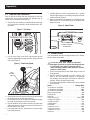
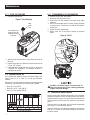
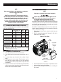
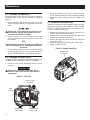
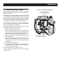
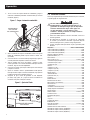
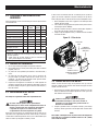
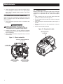
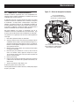
Operation 2.2 STARTING THE GENERATOR Once the fuel and oil levels have been checked and it has been verified there are no loads connected, the generator may be started. Turn the FlexPower Switch OFF (O). 1. Open the fuel valve (Figure 4), located below the starter rope pull, by turning to the valve 90° counter-clockwise to the “ON” (I) position. 7. Carefully adjust the choke to approximately the ½ position until the engine begins to run smoothly, then push the lever all the way to the left (Figure 6). 8. Make sure the bottom of the generator is not blocked by sand, leaves, grass, etc. as the cooling vents are located on the bottom of the unit. Figure 6 - Adjust Choke Figure 4 - Fuel Valve TURNING THE FUEL ON ON I OFF O ENGINE CHOKE OPERATION 2.3 ADDING LOADS 2. Pull up on the center of the fuel fill cap and prime the fuel system by depressing the plunger up to five (5) times with the vent closed (Figure 5). Figure 5 - Prime Fuel System PLUNGER FUEL SYSTEM VENT VENT 3. Open the fuel tank vent on the top of the fuel fill cap by turning the center portion to the “ON” mark (Figure 6). 4. If the engine is cold or has not been run for some time, engage the choke by pushing the choke lever to the right. 5. Grip the handle for the pull starter and brace your other hand against the generator. Pull the rope slowly until resistance is felt, then pull the rope rapidly. 6. If the engine does not start, repeat steps 2-5 until the engine fires and begins to run. 6 Once the generator has been running smoothly for 2-3 minutes, electrical loads can be added. Do not use worn, bare, frayed or otherwise damaged electrical cord sets with the generator. Do not handle any kind of electrical device while standing in water, while barefoot, or while hands or feet are wet. 1. There are two grounded 120 VAC duplex outlets on the front of the generator. 2. DO NOT overload the generator; if the red “overload” LED lights up and the accessories attached to the generator stop operating, stop the engine and reduce the load to the generator. Restart and apply reduced loads. 3. Consult the following table to estimate what can be powered by the generator. Device . . . . . . . . . . . . . . . . . . . . . . . . . . . . . . . .Running Watts *Air Conditioner (12,000 Btu) . . . . . . . . . . . . . . . . . . . . . . . . . 1700 *Air Conditioner (24,000 Btu) . . . . . . . . . . . . . . . . . . . . . . . . . 3800 *Air Conditioner (40,000 Btu) . . . . . . . . . . . . . . . . . . . . . . . . . 6000 Battery Charger (20 Amp) . . . . . . . . . . . . . . . . . . . . . . . . . . . . . 500 Belt Sander (3") . . . . . . . . . . . . . . . . . . . . . . . . . . . . . . . . . . . . 1000 Chain Saw . . . . . . . . . . . . . . . . . . . . . . . . . . . . . . . . . . . . . . . . 1200 Circular Saw (6-1/2") . . . . . . . . . . . . . . . . . . . . . . . . . . 800 to 1000 *Clothes Dryer (Electric) . . . . . . . . . . . . . . . . . . . . . . . . . . . . . 5750 *Clothes Dryer (Gas) . . . . . . . . . . . . . . . . . . . . . . . . . . . . . . . . . 700 *Clothes Washer . . . . . . . . . . . . . . . . . . . . . . . . . . . . . . . . . . . 1150 Coffee Maker . . . . . . . . . . . . . . . . . . . . . . . . . . . . . . . . . . . . . . 1750 *Compressor (1 HP) . . . . . . . . . . . . . . . . . . . . . . . . . . . . . . . . 2000 *Compressor (3/4 HP). . . . . . . . . . . . . . . . . . . . . . . . . . . . . . . 1800 *Compressor (1/2 HP). . . . . . . . . . . . . . . . . . . . . . . . . . . . . . . 1400 Curling Iron . . . . . . . . . . . . . . . . . . . . . . . . . . . . . . . . . . . . . . . . 700