1
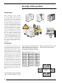
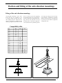
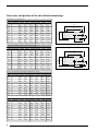
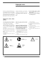
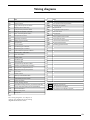
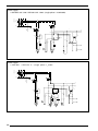
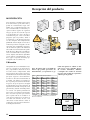
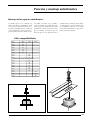
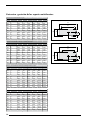
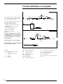
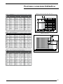
ENGLISH Español INSTALLATION MANUAL Air-cooled heat pumps with high-efficiency scroll compressor MANUAL DE INSTRUCCIONES Bombas de calor condensadas por aire con compresor scroll de alta eficacia anz R407C PRELIMINAY IANZIV. 10/05 6755135_03 replace 0604 6755135_01 This manual contains : Electrical data Electrical wiring Putting into service Wiring diagrams Use MAINTENANCE Electrical data Electrical wiring Putting into service 45 3 Receipt of the product Weights and their distribution on the supports 1 2 Internal hydraulic circuit External hydraulic circuit recommended Position and dimensions Plumbing connections • Plumbing connections Minimum space requirements ENGLISH TABLE OF CONTENTS Receipt of the product 4 Position and fitting of the anti-vibration mountings 5 Plumbing section 7 Electrical wiring 10 Putting into service 11 Improper uses 12 Wiring diagrams 13 Dear Customer, Thank you for choosing AERMEC. It is the fruit of many years of experience and special design studies and it has been made of the highest grade materials and with cutting edge technology. In addition, all our products bear the CE mark indicating that they meet the requirements of the European Machine Directive regarding safety. The standard of quality is permanently being monitored and AERMEC products are therefore a synonym for Safety, Quality and Reliability. If you do not know where our nearest After Sales Service is, you can get this from the dealership where the device was purchased. The data might undergo modifications considered necessary for the improvement of the product. Thank you again. AERMEC S.p.A Receipt of the product HANDLING Before moving the unit, examine the sizes, weights, centre of gravity and lifting points, then check that the equipment for lifting and positioning are suitable and comply with safety regulations currently in force. Particular attention must be paid to all the loading, unloading and lifting operations so as to avoid hazardous situations for people and damage to the structure and operational parts of the machine. Under no circumstances may objects be placed on top of the unit. Personnel engaged in handling the machine must have the proper personal protection devices. Under no circumstance must anybody or anything stop under the unit even briefly. During lifting you are advised to fit anti-vibration mountings and fix them to the relative holes on the base unit in accordance with the mounting schematic supplied with the accessories (VT). Positioning The machines in the ANZ series must be installed externally in an area that is suitable for the purpose that has the required technical spaces. This is essential both to allow interventions of ordinary and extraordinary maintenance and for operating requirements For the proper functioning of the unit it must be installed on a perfectly flat surface. Make sure that the resting surface is able to bear the weight of the machine. The device is made of galvanised steel sheet and hot painted with polyester powders to resist bad weather. This means that no particular measures have to be taken to protect the unit. If the machine is to be placed in a particularly windy position, wind breaks must be provided to avoid the DCPX operating in an unstable condition. N.B. The appliance must be installed in such a way that maintenance and/or 4 repair operations are possible. The warranty of the device does not in any case cover costs incurred as a result of motorised ladders, scaffolding or any other MOD. mm 0207 0257 0307 0417 0507 0807 0907 1007 1507 2007 Minimum technical spaces S1 S2 S3 150 500 150 250 500 250 250 500 250 300 500 300 300 500 300 300 500 300 300 500 300 750 300 750 750 300 750 750 300 750 lifting systems made necessary to carry out the operations under warranty. S4 500 500 500 500 500 500 500 1300 (*) 1300 (*) 1300 (*) in the models with accumulation, the distance S2 becomes 1400 mm (*) Position and fitting of the anti-vibration mountings Fitting of the anti-vibration mountings: Anti-vibration mountings can be combined with the unit (available as an accessory), thanks to which the vibrations produced by the compressor during its functioning are dampened; the following diagrams show how to install these accessories on the unit depending on the model of the unit purchased.Every kit includes four anti-vibration mountings with the nuts and bolts necessary for fitting them; remember to pay particular attention to the positioning of the unit during the fitting of the anti-vibration mountings, furthermore remember that the surface the unit is rested on must be perfectly level and able to support the weight of the unit. Compatibility table: anz VT 7 0207 0257 0307 0417 0507 0807 0907 1007 1507 2007 4 4 4 4 4 4 4 VT 8 VT 9 4 4 4 Versions with accumulation (A-K-J) 0207 0257 0307 0417 0507 0807 0907 1007 1507 2007 4 4 4 4 4 4 4 4 4 4 5 Barycentre and position of the anti-vibration mountings: ANZ H base version (waterless unit) By (mm) A (mm) B (mm) C (mm) D (mm) 020 P 280 140 334 352 650 900 025 P 295 145 334 352 650 900 030 P 300 155 334 352 650 900 041 P 320 185 408 435 660 1120 050 P 410 220 408 435 660 1120 080 P 385 200 408 435 660 1120 090 G 480 280 510 555 1072 1167 100 G 605 430 707 750 1670 1750 150 G 580 430 707 750 1670 1750 200 G 580 430 707 750 1670 1750 Small base(P) Bx (mm) Base anz Version with Accumulation ANZ A (with accumulation empty) By (mm) A (mm) B (mm) C (mm) D (mm) 020 P 385 185 408 435 660 1120 025 P 350 180 408 435 660 1120 030 P 390 200 408 435 660 1120 041 P 420 290 408 435 660 1120 050 G 420 275 510 555 1072 1167 080 G 430 285 510 555 1072 1167 090 G 435 280 510 555 1072 1167 100 G 645 400 707 750 1670 1750 150 G 680 400 707 750 1670 1750 200 G 680 400 707 750 1670 1750 Version with Accumulation ANZ A (with accumulation full of water) anz Base Bx (mm) By (mm) A (mm) B (mm) C (mm) D (mm) 020 P 357 191 408 435 660 1120 025 P 329 187 408 435 660 1120 030 P 355 204 408 435 660 1120 041 P 385 277 408 435 660 1120 050 G 372 274 510 555 1072 1167 080 G 380 281 510 555 1072 1167 090 G 396 278 510 555 1072 1167 100 G 765 393 707 750 1670 1750 150 G 780 394 707 750 1670 1750 200 G 774 394 707 750 1670 1750 Version with accumulation and heating element ANZ K - J (with accumulation full of water) anz Base Bx (mm) By (mm) A (mm) B (mm) C (mm) D (mm) 020 P 357 191 408 435 660 1120 025 P 329 187 408 435 660 1120 030 P 355 204 408 435 660 1120 041 P 385 277 408 435 660 1120 050 G 483 274 510 555 1182 1277 080 G 491 281 510 555 1182 1277 090 G 506 278 510 555 1182 1277 100 G 765 393 707 750 1670 1750 150 G 780 394 707 750 1670 1750 200 G 774 394 707 750 1670 1750 6 Large base (G) Bx (mm) Base anz Plumbing section hydraulic circuit inside the unit N.B. For the correct design of the hydraulic system comply with local safety regulations currently in force. The following information constitutes suggestions for the correct installation of the unit. Standard equipment The unit comes as standard with in the standard versions (°): Plate-type heat exchanger Differential pressure switch between the inlet and outlet of the evaporator to avoid problems of freezing if there is no flow of water. in the versions with accumulation and pump(A): Plate-type heat exchanger Differential pressure switch between the inlet and outlet of the evaporator to avoid problems of freezing if there is no flow of water. For the sizes 020 - 025 - 030 - 041, the differential pressure switch is replaced by a flow switch. Diaphragm type expansion tank with precharge of nitrogen. The storage tank lowers the number of compressor peaks and standardise the temperature of the water to send to the users. Circulation pump Circulation pump Integrated heating element with base which turns on the element on the basis of three mechanical thermostats. in the versions with accumulation and pump (J): Plate-type heat exchanger Differential pressure switch between the inlet and outlet of the evaporator to avoid problems of freezing if there is no flow of water. For the sizes 020 - 025 - 030 - 041, the differential pressure switch is replaced by a flow switch. in the versions with accumulation and pump (K): Plate-type heat exchanger Differential pressure switch between the inlet and outlet of the evaporator to avoid problems of freezing if there is no flow of water. For the sizes 020 - 025 - 030 - 041, the differential pressure switch is replaced by a flow switch. Diaphragm type expansion tank with precharge of nitrogen. The storage tank lowers the number of compressor peaks and standardise the temperature of the water to send to the users. Diaphragm type expansion tank with precharge of nitrogen. The storage tank to lower the number of compressor peaks and standardise the temperature of the water to send to the users. Circulation pump Integrated heating element with basic control which turns the heating element on the basis of a dedicated control, furthermore it has the possibility of managing a three-way valve (not supplied). 7 Recommended hydraulic circuit Recommended hydraulic circuit ANZ (°) The figure shows some diagrams of the recommended hydraulic circuit between the ANZ chiller and the users. In the case the following are not supplied with the unit, you are advised to install: -Manual cut-off valves - Inertia storage tank - Charging assembly - Flexible high-pressure joints - Expansion tank - Safety valve - Drain valve N.B. > The hydraulic piping for connection to the machine must be properly scaled for the actual water flow rate required by the plant in the functioning. The installer is responsible for the hydraulic parallel. The water flow rate to the heat exchanger must always be constant. KEY: ACL Water storage tank Col Manifolds EV Water side heat exchanger FC Fan coil FL Flow switch FM Water filter 8 WATER INLET WATER OUTLET Recommended hydraulic circuit ANZ (A) - (K) WATER INLET WATER OUTLET GCM Automatic loading unit MP Circulation pump PaR Radiating panel PD Differential pressure switch VE Expansion tank VS Safety valve VSF Drain valve VTV Three-way modulating valve VU One-way valve VMI Manual cut-off valves GF Flexible joints SA Air separator with safety valve Plumbing connection positions ANZ 020 - 025 - 030 - 040 - 050 - 080 - 090 Basic version 025 Outlet Inlet 140 250 515,5 030 Outlet Inlet 140 466 477 041 Outlet Inlet 105 466 715 050 Outlet Inlet 105 466 715 080 Outlet Inlet 105 466 715 090 Outlet Inlet 325 466 758 100 Outlet Inlet 340 466 400 150 Outlet Inlet 340 466 400 200 Outlet Inlet 340 466 400 ANZ A Version with accumulation Size A1 A2 A (mm) B (mm) C (mm) 020 Outlet Inlet 431,5 80 108 025 Outlet Inlet 431,5 80 108 030 Outlet Inlet 431,5 80 108 041 Outlet Inlet 431,5 80 108 050 Inlet Outlet 46 130 210 080 Inlet Outlet 46 130 210 090 Inlet Outlet 46 130 210 100 Inlet Outlet 60 130 170 150 Inlet Outlet 60 130 170 200 Inlet Outlet 60 130 170 ANZ 100 - 150 - 200 515,5 C (mm) 250 B (mm) 140 A (mm) Inlet A2 Outlet A1 020 Size ANZ ANZ K - J Version with accumulation and built in heating element Size A1 A2 A (mm) B (mm) C (mm) 020 Outlet Inlet 431,5 80 108 025 Outlet Inlet 431,5 80 108 030 Outlet Inlet 431,5 80 108 041 Outlet Inlet 431,5 80 108 050 Inlet Outlet 160 130 210 080 Inlet Outlet 160 130 210 090 Inlet Outlet 160 130 210 100 Inlet Outlet 60 115 300 150 Inlet Outlet 60 115 300 200 Inlet Outlet 60 115 300 9 Electrical wiring The unit is completely wired in the factory and to start it up it is necessary to have a power supply that works according to the indications on the rating plate of the unit, with cut off with protective devices on the line. The cable cross sections and the scaling of the line main switch are purely indicative. It will be up to the installation engineer to properly dimension the power line depending on the length, type of cable, unit consumption and physical position. ANZ (°) - ANZ A SECT. A SECT. B Terra IL mm2 mm2 mm2 A ANZ (°) - ANZ A SECT. A SECT. B Terra IL mm2 mm2 mm2 A ANZ K - ANZ J SECT. A SECT. B Terra IL mm2 mm2 mm2 A ANZ K - ANZ J SECT. A SECT. B Terra IL 10 mm2 mm2 mm2 A All the electrical wirings must comply with the regulations in force at the time of the installation. The diagrams and schematics in this documentation must only be used as an aid for the setting up of the electrical lines. Refer to the wiring diagram supplied with the device, for installation requirements. N.B. Check that all power cables are cor- rectly secured to the terminals when switched on for the first time and after 30 days of use. Afterwards, check the connection of the power cables every six months. Slack terminals could cause the cables and components to overheat. Cross sections recommended for the maximum length of 50 m. The cross section of the cable and the dimension of the line main switch are purely indicative. (230V single phase) 0207 4 0,5 4 16 0257 4 0,5 4 20 0307 6 0,5 6 25 0417 6 0,5 6 25 (400V three phase) 0207 1,5 0,5 1,5 8 0257 1,5 0,5 1,5 10 0307 2,5 0,5 2,5 10 0417 4 0,5 4 13 0507 4 0,5 4 13 0807 6 0,5 6 16 0907 6 0,5 6 25 1007 10 0,5 10 32 1507 16 0,5 16 40 2007 16 0,5 16 50 0507 6 1 6 20 0807 10 1 10 32 0907 10 1 10 40 1007 16 1 16 50 1507 25 1 16 63 2007 32 1 16 80 (230V single phase) 0207 10 1 10 32 0257 10 1 10 32 0307 10 1 10 45 0417 10 1 10 45 (400V three phase) 0207 4 1 4 16 0257 4 1 4 16 0307 6 1 6 20 0417 6 1 6 20 Putting into service Before putting the unit of the season and refilling at the beginning of the next season. Before start-up check that: – – the system has been filled and the air has been bled; the electrical wirings have been made properly; – the line voltage is within the admitted tolerance limits (±10% of the rated value); WARNING: At least twenty-four hours before the starting up of the unit (or at the end of each long downtime) the unit must be powered up in such a way as to allow the heating elements of the compressor casing to make any refrigerant in the oil evaporate. If this precaution is not performed the compressor could be seriously damaged and the guarantee would no longer be valid. Filling/emptying of the system During the winter period, if the system needs to shut down, the water in the heat exchanger might freeze causing irreparable damage to the heat exchanger itself, the complete emptying of the cooling circuits and sometimes the damage of the compressors. There are three solutions to avoid freezing: Functioning with glycol water with a glycol percentage chosen on the basis of the minimum temperature temperature expected. In this case the different yields and absorption of the chiller, the scaling of the pumps and yield of the terminals must be taken into account. Use of the heat exchange heating elements (available as accessory KR). In this case the element must always be powered for the entire winter period (machine in standby). The complete drainage of the water from the heat exchanger at the end 11 Improper uses The device is designed and built to ensure the maximum safety in its immediate vicinity (IP24) as well as to resist atmospheric agents. The fans are protected with unwanted intrusion of bodies through the protection grilles. The accidental opening of the electrical panel with the machine in operation is prevented by the door lock sectioning device. Do not rest tools or heavy objects on the side heat exchanger coils so as not to ruin the fins. N.B. : Do not introduce objects or allow them to fall through the grilles of the fan motors. Do not lean on the heat exchanger coil: Cutting surfaces. Important safety information The machine must not exceed the pressure and temperature limits indicted in the table shown in the paragraph “Operating limits” technical manual. Correct functioning is not guaranteed after a fire; before starting up the machine again, contact an authorised after sales centre. The machine is fitted with safety valves that in the case of excessive pressure can discharge hot gases into the atmosphere. Wind, earthquakes and other natural phenomena of exceptional intensity have not been considered. Danger: Voltage Danger: Temperature 12 If the unit is used in aggressive atmosphere or with aggressive water consult head office. Following extraordinary maintenance carried out on refrigeration circuits, with the replacement of components, carry out the following operations before starting up the machine again: Pay the closest attention when restoring the refrigerant load indicated on the machine's rating plate (inside the electrical panel). and the grounding. Check the plumbing connections. Check that the water pump works properly. Clean the water filters. Check that the condenser coils are not dirty or clogged. Check the proper rotation of the fan unit. Open all the taps on the refrigerating circuit. Correctly connect the power supply Danger: Cut off the power Danger: Moving parts Danger!!! Wiring diagrams KEY KEY AA Auxiliary start up relay SUW Water outlet probe AE External alarm TCP Compressor thermal protection AP High pressure pressure switch TMP Thermal pump switch AT Auxiliary thermostat relay TEB By-pass timer BP Low pressure pressure switch TEC Compressor start-up timer CD Triangle compressor contactor TER Self start timer C/F Hot/ cold changeover switch TR transformer CCP Compressor contact TER Cold regulation thermostat CM Operating condenser VIC Cycle inversion valve CMP Motor pump contactor VSL Liquid cut-off solenoid valve CP Compressor VSB By-pass solenoid valve CV Fan contactor TGP Pressing gas thermostat CVC Condensing fan contactor CVE Evaporating fan contactor DCP Low ambient temperature device IA Auxiliary ON / OFF switch IL Line main switch L Power phase LB Shutdown light LF Operating light MP Compressor protection module MTA Auxiliary magnetho-thermal switch MTCP Compressor magnetho-thermal MTMP Magnetho-thermal pump switch MV Fan motor N Feedin neutral Pa Start up and release button PD Differential pressure switch PE Earth connection R Casing heating element RE Antifreeze heating element ( accessories KR - RA) Optional components RP Pump antifreeze heating element (5A 250V) Components not supplied SCV Fan control card Connections to be wired on job site SWI Water inlet probe SS Coil probe N.B. The wiring diagrams are subject to change, you should refer to the wiring diagram attached to the device. 13 230V 50Hz Power supply ANZ 020 - 025 - 030 / ANZ 020 - 025 - 030 A (single phase 1 230V-50Hz) ~ L' N' 3 4 1 2 IL 1 3 2 4 SEZ. A PE 1 3 2 4 MTA 1 MTCP L 2 SCV N 1 2 1 CCP 3 2 4 0 6 5 5 6 4 16 16A CCP R 1 CM P S M BL AP1 NE 1 CP 24 3 1 S C 0 22 A CM R TR 21 10 C 230 Y GND 3 11 1A 12 MA 6 6A M R 0V MV 24V 230V 50Hz Power supply ANZ 041 / ANZ 041 A (single phase 1 ~ 230V- L N 3 4 1 2 IL SEZ. A PE 1 3 2 4 MTA MTCP 1 3 2 4 1 L' 2 SCV 1 0 2 1 CCP 3 N' 4 5 A 6 Y GND 3 4 0 21 CCP 16 C 16A BL S R 1 M S AP1 CM NE P C 24 22 3 CM R 14 TR CIRCUITO DI POTENZA/POWER CONNECTIONS 2 CP 230 6 5 BL NE 1 MV1 CM NE MA MA 1 BL BL M NE 1 MV2 M 1A 11 12 MA MA 6 6A R 0V 24V Power supply ANZ 020 - 025 - 030 / ANZ 020 - 025 - 030 A L3 400V 50Hz L2 L1 N' 7 8 5 6 3 4 1 2 IL 1 3 2 4 PE SEZ. A MTA 1 1 3 L 2 5 SCV N 1 2 2 MTCP 4 0 6 6 5 4 CCP 1 3 5 2 4 6 CCP A 16A C R 3 BL P S M NE 1 AP1 24 22 3 CM CP TR 0 21 10 16 230 Y GND 3 1 6 12 11 1A MA 6A M R 0V MV 24V Power supply ANZ 041 - 050 - 080 / ANZ 041 A L3 L1 N 7 8 5 6 3 4 1 2 IL 1 3 2 4 PE MTA SEZ. A 400V 50Hz L2 1 1 3 5 2 4 6 L 2 MTCP SCV 1 N' 0 2 230 TR 6 5 A Y GND 3 4 0 21 1 CCP 3 2 4 5 6 CCP 16 3 16A BL CM NE C CP R 3 M S 24 P AP1 22 BL NE 1 MV1 CM NE MA MA 1 BL BL M NE 1 M 1A 11 12 MA MA 6 6A R 0V 24V MV2 15 Power supply ANZ 050 - 080 A Power supply ANZ 090 / ANZ 090 A CIRCUITO DI POTENZA/POWER CONNECTIONS 16 Power supply ANZ 100 - 150 - 200 / ANZ 100 - 150 - 200 A Load connection ANZ 020 - 025 - 030 - 041 - 050 - 080 17 Load connections ANZ 020 - 025 - 030 - 041 A Load connection ANZ 090 18 Load connections ANZ 090 A Load connections ANZ 100 - 150 - 200 19 Load connections ANZ 100 - 150 - 200 A Remote control ANZ 020 - 025 - 030 - 041 - 050 - 080 / ANZ 020 - 025 - 030 - 041 - 050 - 080 A ALARM Ø 0,5 mm2 max 10m Ø 0,5 mm2 max 30m 20 Alla morsettiera dell' unità To electric box Remote control ANZ 090 / ANZ 090 A 21 Remote control ANZ 100 - 150 - 200 A 22 Power supply ANZ 020 - 025 - 030 K Power supply ANZ 041 K 23 Power supply ANZ 050 - 080 K Power supply ANZ 090 K 24 Power supply ANZ 100 - 150 - 200 K Load connections ANZ 020 - 025 - 030 K 25 Load connections ANZ 041 K Load connections ANZ 050 - 080 K 26 Load connections ANZ 090 K Load connections ANZ 100 - 150 - 200 K 27 Remote control ANZ 020 - 025 - 030 K Remote control ANZ 041 K 28 Remote control ANZ 050 - 080 K Remote control ANZ 100 - 150 - 200 K 29 Contenido del manual: Datos eléctricos Conexiones eléctricas Puesta en funcionamiento Esquemas eléctricos Uso Mantenimiento Datos eléctricos Conexiones eléctricas Puesta en funcionamiento 45 3 Recepción del producto Pesos y distribución en los soportes 1 2 Circuito hidráulico Interno Circuito hidráulico externo recomendado Posición y dimensiones conexiones hidráulicas Conexiones hidráulicas Distancias técnicas mínimas Español Índice Recepción del producto 32 Posición y montaje antivibrantes 33 Sección hidráulica 35 CONEXIONES ELÉCTRICAS 38 Puesta en marcha 39 Usos incorrectos 40 Esquemas eléctricos 41 Estimado cliente, Le agradecemos su elección por un producto AERMEC. Este producto es el resultado de varios años de experiencia y de estudios de proyectación minuciosos, y ha sido construido con materiales de primera calidad y tecnología de vanguardia. Además, la marca CE garantiza que los aparatos cumplan los requisitos de la Directiva Europea Máquinas por lo que se refiere a la seguridad. Nuestro nivel de calidad está sometido a una vigilancia constante, por lo que los productos AERMEC son sinónimo de Seguridad, Calidad y Fiabilidad. Sobre nuestro servicio de asistencia más cercano, si se desconoce, se puede obtener información en el concesionario donde ha adquirido al aparato. Los datos pueden sufrir modificaciones, consideradas necesarias para una mejora del producto. Gracias de nuevo. AERMEC S.p.A Recepción del producto MOVILIZACIÓN Antes de mover la unidad asegúrese bien de las dimensiones, pesos, baricentro, y puntos de levantamiento, luego comprobar que el equipamiento para realizar el levantamiento sea adecuado y respete las normas vigentes de seguridad. Hay que prestar una atención especial a las operaciones de carga, descarga y levantamiento para evitar situaciones peligrosas para las personas, daños a la carpintería y a los órganos funcionales de la máquina. Está completamente prohibido colocar objetos encima de la unidad. El personal encargado a la movilización de la unidad debe estar provisto de medios de protección individual adecuados. Está terminantemente prohibido detenerse debajo de la unidad Durante el levantamiento se aconseja montar los soportes antivibrantes fijándolos en los orificios correspondientes de la base según el esquema de montaje que acompaña a los accesorios (VT). Ubicación Los aparatos de la serie ANZ deben instalarse en el exterior, en un lugar adecuado, y respetando las distancias técnicas necesarias. Esto es indispensable, tanto para permitir las operaciones rutinarias y extraordinarias de mantenimiento, como por puras exigencias de funcionamiento. Para un correcto funcionamiento de la unidad, ésta deberá ser instalada sobre un plano perfectamente horizontal. Asegúrese de que la superficie de apoyo pueda soportar el peso de la máquina. El aparato está realizado en chapa de acero galvanizada y tratada utilizando pintura en caliente con polvos poliuretánicos para resistir a la intemperie. Por lo tanto, no se necesitan especiales precauciones para la protección de la unidad. En el caso de que la máquina se encuentre en una zona con corrientes de aire, seria conveniente instalar barreras contra el viento para evitar un mal funcionamiento del dispositivo DCPX. Nota: El aparato debe ser instalado de manera que permita operaciones de mantenimiento y/o reparación. La gaMod. mm 0207 0257 0307 0417 0507 0807 0907 1007 1507 2007 Distancias técnicas mínimas S1 S2 S3 150 500 150 250 500 250 250 500 250 300 500 300 300 500 300 300 500 300 300 500 300 750 300 750 750 300 750 750 300 750 rantía del aparato no cubrirá en ningún caso los costes derivados del uso de escaleras automáticas, andamios o cualquier otro sistema de elevación necesario para realizar las operaciones cubiertas por la garantía. S4 500 500 500 500 500 500 500 1300 (*) 1300 (*) 1300 (*) en los modelos con acumulación, la distancia S2 es de 1400 mm (*) 32 Posición y montaje antivibrantes Montaje de los soportes antivibrantes: Es posible aplicar a las unidades soportes antivibrantes (disponibles como accesorio), que permiten atenuar las vibraciones producidas por el compresor en funcionamiento; en los esquemas siguientes podrá consultar cómo se insta- lan dichos accesorios en las unidades, según el modelo de unidad adquirida. Cada juego está compuesto por cuatro antivibrantes, con la pernería necesaria para su montaje; recuerde prestar una atención especial a la colocación de la unidad durante el montaje de los soportes antivibrantes; recuerde además que la unidad debe colocarse en un plano perfectamente horizontal y capaz de soportar el peso del aparato. Tabla compatibilidades: anz VT 7 0207 0257 0307 0417 0507 0807 0907 1007 1507 2007 4 4 4 4 4 4 4 VT 8 VT 9 4 4 4 Versiones con Acumulación (A-K-J) 0207 0257 0307 0417 0507 0807 0907 1007 1507 2007 4 4 4 4 4 4 4 4 4 4 33 Baricentro y posición de los soportes antivibrantes: Versión básica ANZ H (unidad sin agua) By (mm) A (mm) B (mm) C (mm) D (mm) 020 P 280 140 334 352 650 900 025 P 295 145 334 352 650 900 030 P 300 155 334 352 650 900 041 P 320 185 408 435 660 1120 050 P 410 220 408 435 660 1120 080 P 385 200 408 435 660 1120 090 G 480 280 510 555 1072 1167 100 G 605 430 707 750 1670 1750 150 G 580 430 707 750 1670 1750 200 G 580 430 707 750 1670 1750 Base pequeña (P) Bx (mm) Placa anz Versión con Acumulación ANZ A (con acumulación vacía) By (mm) A (mm) B (mm) C (mm) D (mm) 020 P 385 185 408 435 660 1120 025 P 350 180 408 435 660 1120 030 P 390 200 408 435 660 1120 041 P 420 290 408 435 660 1120 050 G 420 275 510 555 1072 1167 080 G 430 285 510 555 1072 1167 090 G 435 280 510 555 1072 1167 100 G 645 400 707 750 1670 1750 150 G 680 400 707 750 1670 1750 200 G 680 400 707 750 1670 1750 Versión con Acumulación ANZ A (con acumulación llena de agua) anz Placa Bx (mm) By (mm) A (mm) B (mm) C (mm) D (mm) 020 P 357 191 408 435 660 1120 025 P 329 187 408 435 660 1120 030 P 355 204 408 435 660 1120 041 P 385 277 408 435 660 1120 050 G 372 274 510 555 1072 1167 080 G 380 281 510 555 1072 1167 090 G 396 278 510 555 1072 1167 100 G 765 393 707 750 1670 1750 150 G 780 394 707 750 1670 1750 200 G 774 394 707 750 1670 1750 Versión con Acumulación y resistencia ANZ K - J (con acumulación llena de agua) anz Placa Bx (mm) By (mm) A (mm) B (mm) C (mm) D (mm) 020 P 357 191 408 435 660 1120 025 P 329 187 408 435 660 1120 030 P 355 204 408 435 660 1120 041 P 385 277 408 435 660 1120 050 G 483 274 510 555 1182 1277 080 G 491 281 510 555 1182 1277 090 G 506 278 510 555 1182 1277 100 G 765 393 707 750 1670 1750 150 G 780 394 707 750 1670 1750 200 G 774 394 707 750 1670 1750 34 Base grande (G) Bx (mm) Placa anz Sección hidráulica circuito hidráulico interior de la unidad Nota: Para realizar una configuración correcta del sistema hidráulico, siga la normativa local de seguridad en vigor. La información siguiente le sugiere cómo realizar una correcta instalación de la unidad. Dotación de serie La unidad está equipada de serie en las versiones Estándar (°): Intercambiador de chapa Presostato diferencial entre la entrada y la salida del evaporador para evitar problemas de congelación en caso de falta de circulación del agua. en las versiones con acumulación y bomba (A): Intercambiador de chapa Presostato diferencial entre la entrada y la salida del evaporador para evitar problemas de congelación en caso de falta de circulación del agua. Para los tamaños 020 - 025 - 030 - 041, se sustituye el presostato diferencial del agua que hay que enviar a los distintos usos. por un flujostato. Vaso de expansión con membrana precargada con nitrógeno. Depósito de acumulación para disminuir el número de tomas de fuerza del compresor y uniformar la temperatura del agua que hay que enviar a los distintos usos. Bomba de circulación Intercambiador de chapa Presostato diferencial entre la entrada y la salida del evaporador para evitar problemas de congelación en caso de falta de circulación del agua. Para los tamaños 020 - 025 - 030 - 041, se sustituye el presostato diferencial por un flujostato. Intercambiador de chapa Presostato diferencial entre la entrada y la salida del evaporador para evitar problemas de congelación en caso de falta de circulación del agua. Para los tamaños 020 - 025 - 030 - 041, se sustituye el presostato diferencial por un flujostato. Vaso de expansión con membrana precargada con nitrógeno. Depósito de acumulación para disminuir el número de tomas de fuerza del compresor y uniformar la temperatura Resistencia integrativa con control básico, que activa la resistencia según tres termostatos mecánicos. en las versiones con acumulación y bomba (J): en las versiones con acumulación y bomba (K): Bomba de circulación. Vaso de expansión con membrana precargada con nitrógeno. Depósito de acumulación para disminuir el número de tomas de fuerza del compresor y uniformar la temperatura del agua que hay que enviar a los distintos usos. Bomba de circulación. Resistencia integrativa con control básico que activa la resistencia según el control dedicado y tiene además la posibilidad de controlar una válvula de tres vías (no incluida). 35 Circuito hidráulico aconsejado Circuito hidráulico recomendado ANZ (°) En las figuras aparecen varios esquemas del circuito hidráulico recomendado entre el chiller ANZ y los usos. En caso de que no estén incluidos con la unidad, se aconseja instalar: -Válvulas manuales de cierre - Depósito de acumulación inercial - Grupo de carga - Juntas flexibles de alta presión – recipiente de expansión Válvula de seguridad - Válvula de ventilación Notas: Las tuberías hidráulicas de conexión a la máquina deben tener las dimensiones adecuadas para el caudal efectivo de agua demandado por el sistema en funcionamiento. el paralelo hidráulico lo realiza el instalador. El caudal del agua en el intercambiador debe ser siempre constante. Leyenda: ACL Depósito de acumulación de agua Col Colectores EV Intercambiador lado agua FC Fan coil FL flujostato FM Filtro agua 36 ENTRADA AGUA SALIDA AGUA Circuito hidráulico recomendado ANZ (A) - (K) ENTRADA AGUA SALIDA AGUA GCM Grupo carga automático MP Bomba de circulación PaR Paneles radiantes PD Presostato diferencial VE Vaso de expansión VS Válvula de seguridad VSF Válvula de ventilación aire VTV Válvula de tres vías modulante VU Válvula unidireccional VMI Válvulas manuales de cierre GF Juntas flexibles SA Separador de aire con válvula de seguridad Posiciones conexiones hidráulicas ANZ 020 - 025 - 030 - 040 - 050 - 080 - 090 Versión básica 025 Salida Entrada 140 250 515,5 030 Salida Entrada 140 466 477 041 Salida Entrada 105 466 715 050 Salida Entrada 105 466 715 080 Salida Entrada 105 466 715 090 Salida Entrada 325 466 758 100 Salida Entrada 340 466 400 150 Salida Entrada 340 466 400 200 Salida Entrada 340 466 400 ANZ A Versión con acumulación medida A1 A2 A (mm) B (mm) C (mm) 020 Salida entrada 431,5 80 108 025 Salida entrada 431,5 80 108 030 Salida entrada 431,5 80 108 041 Salida entrada 431,5 80 108 050 entrada Salida 46 130 210 080 entrada Salida 46 130 210 090 entrada Salida 46 130 210 100 entrada Salida 60 130 170 150 entrada Salida 60 130 170 200 entrada Salida 60 130 170 ANZ 100 - 150 - 200 515,5 C (mm) 250 B (mm) 140 A (mm) Entrada A2 Salida A1 020 medida ANZ ANZ K - J Versión con acumulación y resistencia integrativa medida A1 A2 A (mm) B (mm) C (mm) 020 Salida entrada 431,5 80 108 025 Salida entrada 431,5 80 108 030 Salida entrada 431,5 80 108 041 Salida entrada 431,5 80 108 050 entrada Salida 160 130 210 080 entrada Salida 160 130 210 090 entrada Salida 160 130 210 100 entrada Salida 60 115 300 150 entrada Salida 60 115 300 200 entrada Salida 60 115 300 37 conexiones eléctricas Todas las instalaciones eléctricas de la unidad vienen acabadas de fábrica. Para ponerla en marcha, se necesita una alimentación eléctrica de acuerdo con las indicaciones de la tarjeta de características de la unidad, que encontrará junto a las protecciones en línea. Las secciones de los cables y el dimensionamiento del interruptor de línea son puramente indicativas. El instalador debe determinar las dimensiones oportunas para la línea de alimentación en función de la longitud, del tipo de cable, de la absorción de la ANZ (°) - ANZ A SEZ A SEZ B Tierra IL mm2 mm2 mm2 A ANZ (°) - ANZ A SEZ A SEZ B Tierra IL mm2 mm2 mm2 A ANZ K - ANZ J SEZ A SEZ B Tierra IL mm2 mm2 mm2 A ANZ K - ANZ J SEZ A SEZ B Tierra IL 38 mm2 mm2 mm2 A unidad y de la dislocación física. Todas las conexiones eléctricas deben respetar la normativa vigente en el momento de la instalación. Los diagramas incluidos en esta documentación deben utilizarse sólo como auxilio para la ubicación de las líneas eléctricas. En cuanto a las necesidades de instalación, consulte el esquema eléctrico suministrado con el aparato. Nota: Compruebe el calibrado de todas las abrazaderas de los conductores de potencia a la primera puesta en marcha y después de 30 días. Posteriormente, verifique el calibrado de todas las abrazaderas de potencia cada semestre. Si los terminales están aflojados, puede producirse un sobrecalentamiento de los cables y de los componentes. Sección aconsejada para una longitud máxima de 50 m. La sección de los cables y las dimensiones del interruptor de línea son de carácter puramente indicativo. (230V monofásico) 0207 4 0,5 4 16 0257 4 0,5 4 20 0307 6 0,5 6 25 0417 6 0,5 6 25 (400V trifásico) 0207 1,5 0,5 1,5 8 0257 1,5 0,5 1,5 10 0307 2,5 0,5 2,5 10 0417 4 0,5 4 13 0507 4 0,5 4 13 0807 6 0,5 6 16 0907 6 0,5 6 25 1007 10 0,5 10 32 1507 16 0,5 16 40 2007 16 0,5 16 50 0507 6 1 6 20 0807 10 1 10 32 0907 10 1 10 40 1007 16 1 16 50 1507 25 1 16 63 2007 32 1 16 80 (230V monofásico) 0207 10 1 10 32 0257 10 1 10 32 0307 10 1 10 45 0417 10 1 10 45 (400V trifásico) 0207 4 1 4 16 0257 4 1 4 16 0307 6 1 6 20 0417 6 1 6 20 PUESTA EN FUNCIÓN Antes de poner en marcha presores puedan evaporar el refrigerante presente en el aceite. Para evitar el peligro del hielo existen tres soluciones posibles: Antes de la puesta en marcha se aconseja verificar que: la instalación está cargada y se ha purgado el aire; las conexiones eléctricas se han realizado correctamente; la tensión de la línea se encuentra dentro de los niveles de tolerancia admitidos (±10% del valor nominal); ATENCIÓN: Al menos 24 horas antes de la puesta en función de la unidad (o al final de cada periodo de pausa prolongado) se debe conectar la unidad a la corriente eléctrica para que las resistencias de calentamiento del cárter de los com- El no cumplimiento de esta precaución puede causar graves daños al compresor y comporta la extinción de la garantía. Carga / descarga de la instalación: Durante el periodo invernal, en caso de no se utilice la instalación, el agua presente en el intercambiador puede helarse y causar así daños irreparables al propio intercambiador, la descarga completa de los circuitos de refrigeración y, a veces, la rotura de los compresores. Descarga completa del agua del intercambiador al final de la temporada, y llenado al comienzo de la temporada siguiente. Funcionamiento con agua glicolada, con un porcentaje de glicol en función de la temperatura mínima exterior prevista. En este caso habrá que tener en cuenta los distintos rendimientos y absorciones del refrigerador, el tamaño de las bombas y el rendimiento de los terminales. Uso de resistencias de calentamiento del intercambiador (disponible como accesorio KR). En tal caso las resistencias deben estar siempre bajo tensión, durante todo el periodo de posible hielo (máquina en modo espera). 39 usos incorrectos El aparato está proyectado y construido para garantizar la máxima seguridad en sus inmediatas cercanías (IP24), así como para resistir a los agentes atmosféricos. Los ventiladores se encuentran protegidos de intrusiones involuntarias mediante rejillas de protección. La aper- tura accidental del tablero eléctrico con máquina en funcionamiento se evita gracias al seccionador sujetapuerta. Evítese apoyar utensilios u objetos pesados directamente sobre las baterías laterales del cambio térmico, para no estro- pear las aletas. Nota: No introduzca ni deje caer objetos a través de las rejillas de los motores de los ventiladores. No se apoye en las baterías de intercambio térmico: superficie cortante. Importantes informaciones de seguridad La máquina no debe superar los límites de presión y temperatura indicados en el cuadro presentado en el apartado “Límites de funcionamiento” del manual técnico. Después de un incendio no se garantiza el correcto funcionamiento; antes de volver a encender la máquina póngase en contacto con un centro de asistencia autorizado. La máquina está dotada de válvulas de seguridad que en el caso de excesiva presión pueden descargar gas a alta temperatura en la atmósfera. El viento, los terremotos y otros fenómenos natu ¡Peligro! Corriente eléctrica ¡Peligro! Temperatura 40 rales especialmente intensos no se han tenido en cuenta. En caso de empleo de la unidad en atmósfera agresiva o con agua agresiva consultar la sede. Después de haber realizado intervenciones de mantenimiento en el circuito de refrigeración con sustituciones de componentes, se aconseja realizar las siguientes operaciones antes de volver a encender la máquina: Tenga muchísimo cuidado cuando reponga la carga del refrigerante indicada en la placa de la máquina (dentro del cuadro eléctrico). ¡Peligro! Quitar la corriente eléctrica ¡Peligro! Órganos en movimiento Abra todos los grifos del circuito de refrigeración. Conecte correctamente la alimentación eléctrica y la toma de tierra Comprobar las conexiones hidráulicas. Compruebe que la bomba de agua funciona correctamente Limpiar los filtros del agua. Comprobar que las baterías del condensador no estén sucias u obstruidas . Comprobar la correcta rotación del grupo ventiladores. ¡Peligro! esquemas eléctricos Nota Nota AA Relé auxiliar de encendido TCP Protección térmica compresor AE Alarma externa TMP Térmico Bomba AP Presostato de alta presión TEB Temporizador de by-pass AT Relé auxiliar termostato TEC Temporizador encendido compresor BP Presostato de baja presión TER Temporizador encendido automático CD Contactor Triángulo compresor TR transformador C/F Interruptor de cambio calor / frío TER Termostato ajuste frío CCP contactor compresor VIC Válvula de inversión del ciclo CM Condensador de marcha VSL Válvula solenoide cierre líquido CMP Contactor motobomba VSB Válvula solenoide de by-pass CP COMPRESOR TGP Termostato gas impelente CV contactor ventilador CVC Contactor ventilador condensador CVE Contactor ventilador evaporador DCP dispositivo baja temperatura IA Interruptor auxiliar ON / OFF IL Interruptor de línea L Fase de alimentación LB Lámpara de bloqueo LF Lámpara de funcionamiento MP módulo de protección del compresor MTA magnetotérmico auxiliar MTCP Magnetotérmico compresor MTMP Magnetotérmico bomba MV Motor ventilador N neutro de alimentación Pa Pulsador de encendido y desbloqueo PD presostato diferencial PE Conexión tierra r Resistencia cárter componentes suministrados opcionales RE Resistencia antihielo (accesorios KR - RA) Componentes no suministrados RP Resistencia antihielo bomba (5A 250V) SCV Tarjeta de control ventiladores conexiones que deben realizarse durante la instalación SWI sonda entrada agua SS Sonda batería SUW Sonda salida agua Nota: Los esquemas eléctricos pueden haber sido actualizados, por lo que es conveniente consultar el esquema eléctrico que acompaña al aparato. 41 230V 50Hz Alimentación ANZ 020 - 025 - 030 / ANZ 020 - 025 - 030 A (monofásico 1 230V-50Hz) ~ L' N' 3 4 1 2 IL 1 3 2 4 SEZ. A PE 1 3 2 4 MTA 1 MTCP L 2 SCV N 1 2 1 CCP 3 2 4 0 6 5 5 6 4 16 16A CCP R 1 CM P S M BL AP1 NE 1 CP 24 3 1 S C 0 22 A CM R TR 21 10 C 230 Y GND 3 11 1A 12 MA 6 6A M R 0V MV 24V 230V 50Hz Alimentación ANZ 041 / ANZ 041 A (monofásico 1 230V-50Hz) ~ L N 3 4 1 2 IL SEZ. A PE 1 3 2 4 MTA MTCP 1 3 2 4 1 L' 2 SCV 1 0 2 1 CCP 3 N' 4 5 A 6 Y GND 3 4 0 21 CCP 16 C 16A BL S R 1 M S AP1 CM NE P C 24 22 3 CM R 42 TR CIRCUITO DI POTENZA/POWER CONNECTIONS 2 CP 230 6 5 BL NE 1 MV1 CM NE MA MA 1 BL BL M NE 1 MV2 M 1A 11 12 MA MA 6 6A R 0V 24V Alimentación ANZ 020 - 025 - 030 / ANZ 020 - 025 - 030 A L3 400V 50Hz L2 L1 N' 7 8 5 6 3 4 1 2 IL 1 3 2 4 PE SEZ. A MTA 1 1 3 L 2 5 SCV N 1 2 2 MTCP 4 0 6 6 5 4 CCP 1 3 5 2 4 6 CCP A 16A C R 3 BL P S M NE 1 AP1 24 22 3 CM CP TR 0 21 10 16 230 Y GND 3 1 6 12 11 1A MA 6A M R 0V MV 24V Alimentación ANZ 041 - 050 - 080 / ANZ 041 A L3 L1 N 7 8 5 6 3 4 1 2 IL 1 3 2 4 PE MTA SEZ. A 400V 50Hz L2 1 1 3 5 2 4 6 L 2 MTCP SCV 1 N' 0 2 230 TR 6 5 A Y GND 3 4 0 21 1 CCP 3 2 4 5 6 CCP 16 3 16A BL CM NE C CP R 3 M S 24 P AP1 22 BL NE 1 MV1 CM NE MA MA 1 BL BL M NE 1 M 1A 11 12 MA MA 6 6A R 0V 24V MV2 43 Alimentación ANZ 050 - 080 A Alimentación ANZ 090 / ANZ 090 A CIRCUITO DI POTENZA/POWER CONNECTIONS 44 Alimentación ANZ 100 - 150 - 200 / ANZ 100 - 150 - 200 A CONEXIÓN CARGAS ANZ 020 - 025 - 030 - 041 - 050 - 080 45 Conexiones cargas ANZ 020 - 025 - 030 - 041 A CONEXIÓN CARGAS ANZ 090 46 Conexiones cargas ANZ 090 A Conexiones cargas ANZ 100 - 150 - 200 47 Conexiones cargas ANZ 100 - 150 - 200 A Control a distancia ANZ 020 - 025 - 030 - 041 - 050 - 080 / ANZ 020 - 025 - 030 - 041 - 050 - 080 A ALARM Ø 0,5 mm2 max 10m Ø 0,5 mm2 max 30m 48 Alla morsettiera dell' unità To electric box Control a distancia ANZ 090 / ANZ 090 A 49 Control a distancia ANZ 100 - 150 - 200 A 50 Alimentación ANZ 020 - 025 - 030 K Alimentación ANZ 041 K 51 Alimentación ANZ 050 - 080 K Alimentación ANZ 090 K 52 Alimentación ANZ 100 - 150 - 200 K Conexiones cargas ANZ 020 - 025 - 030 K 53 Conexiones cargas ANZ 041 K Conexiones cargas ANZ 050 - 080 K 54 Conexiones cargas ANZ 090 K Conexiones cargas ANZ 100 - 150 - 200 K 55 Control a distancia ANZ 020 - 025 - 030 K Control a distancia ANZ 041 K 56 Control a distancia ANZ 050 - 080 K Control a distancia ANZ 100 - 150 - 200 K 57 AERMEC S.p.A. 37040 Bevilacqua (VR) - Italy Via Roma, 44 - Tel. (+39) 0442 633111 Telefax (+39) 0442 93730 – (+39) 0442 93566 www.aermec.com Los datos técnicos contenidos en este documento no son vinculantes. AERMEC se reserva la facultad de aportar, en cualquier momento, todas las modificaciones consideradas necesarias para la mejora del producto. carta riciclata recycled paper papier recyclé recycled Papier The technical data in the following documentation are not binding. Aermec reserves the right to make all the modifications considered necessary for improving the product at any time.