1
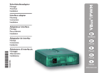
Montage Anschluss Installation Interface adapter Mounting Connection Installation Adaptateur interface Montage Raccordement Commande VBus® / LAN Schnittstellenadapter de 11201618 *11201618* Handbuch en Manual fr Manuel Inhaltsverzeichnis Sicherheitshinweise Technische Daten ....................................................4 Montage.....................................................................4 Elektrischer Anschluss.............................................5 Systemzugriff über RSC-Software.........................7 Einrichtung im Netzwerk........................................9 LED an der Gehäuseoberseite..............................11 Glossar.....................................................................12 Wichtiger Hinweis.................................................14 Bitte beachten Sie diese Sicherheitshinweise genau, um Gefahren und Schäden für Menschen und Sachwerte auszuschließen. Vielen Dank für den Kauf dieses Gerätes. Bitte lesen Sie diese Anleitung sorgfältig durch, um die Leistungsfähigkeit dieses Gerätes optimal nutzen zu können. de VBus®/LAN Input: 12 V /0,5 A 5.5 x 2.5 mm - + Symbolerklärung ACHTUNG! Warnhinweise sind mit einem Warndrei- eck gekennzeichnet! ÎÎ Es wird angegeben, wie die Gefahr vermieden werden kann! Signalwörter kennzeichnen die Schwere der Gefahr, die auftritt, wenn sie nicht vermieden wird. • ACHTUNG bedeutet, dass Sachschäden auftreten können • WARNUNG bedeutet, dass schwere Personenschäden oder sogar Lebengefahr auftreten können ÎÎ Textabschnitte, die mit einem Pfeil gekennzeichnet sind, fordern zu einer Handlung auf. Hinweis Hinweise sind mit einem Informations symbol gekennzeichnet. Irrtum und technische Änderungen vorbehalten. © 20120504_11201618_VBus_LAN_A6.mon3s.indd 2 Zielgruppe Entsorgung Elektroarbeiten dürfen nur von Elektrofachkräften durchgeführt werden. Die erstmalige Inbetriebnahme hat durch den Ersteller der Anlage oder einen von ihm benannten Fachkundigen zu erfolgen. • Verpackungsmaterial des Gerätes umweltgerecht entsorgen. • Altgeräte müssen durch eine autorisierte Stelle umweltgerecht entsorgt werden. Auf Wunsch nehmen wir Ihre bei uns gekauften Altgeräte zurück und garantieren für eine umweltgerechte Entsorgung. Beachten Sie bei Arbeiten die jeweiligen, gültigen Normen, Vorschriften und Richtlinien! Angaben zum Gerät Bestimmungsgemäße Verwendung Der Schnittstellenadapter VBus®/LAN darf nur für die Verbindung zwischen einem Gerät mit RESOL VBus® und einem Computernetzwerk unter Berücksichtigung der in dieser Anleitung angegebenen technischen Daten verwendet werden. Die bestimmungswidrige Verwendung führt zum Ausschluss jeglicher Haftungsansprüche. CE-Konformitätserklärung Das Produkt entspricht den relevanten Richtlinien und ist daher mit der CE-Kennzeichnung versehen. Die Konformitätserklärung kann beim Hersteller angefordert werden. Übersicht • Der Netzwerkanschluss für die Solaranlage • Zugriff auf Anlagendaten vom gesamten Netzwerk aus • Fernparametrisierung des Reglers über VBus® • RSC-Software auf CD-ROM inklusive Der Schnittstellenadapter VBus®/LAN dient dem Anschluss des Reglers an einen PC oder einen Router und erlaubt damit einen komfortablen Zugriff auf den Regler über das lokale Netzwerk des Betreibers. So kann von jeder Netzwerkstation aus auf den Regler zugegriffen, die Anlage parametrisiert sowie die aufgezeichneten Daten bilanziert werden. Der Adapter ist für den Anschluss an Regler mit RESOL VBus® konzipiert. 3 de Vorschriften de Technische Daten Gehäuse: Kunststoff Schutzart: IP 20 (EN 60529) Umgebungstemperatur: 0 ... 40 °C Abmessungen: 95 × 70 × 25 mm Einbau: Wandmontage (optional) Anzeige: 1 zweifarbige LED an der Gehäuseoberseite 2 LED am RJ45-Anschluss Versorgung: Eingangsspannung Steckernetzteil: 100 ... 240 V~ / 50-60 Hz Eingangsspannung Adapter: 12 V / 0,5 A5.5 × 2.5 mm Schnittstelle: RESOL VBus® RJ45-LAN-Anschluss Unterstützte Betriebssysteme: Windows XP, Windows Vista, Windows 7 4 Montage Die Montage darf ausschließlich in trockenen Innenräumen erfolgen. Der Schnittstellenadapter ist klein und leicht, so dass eine Wandmontage nicht unbedingt notwendig ist. Er kann auf dem Schreibtisch oder einem Anlagenbauteil abgelegt werden (zulässige Umgebungstemperatur beachten!). Es liegen vier selbstklebende, rutschfeste Gummifüßchen bei, die bei Bedarf in den entsprechenden Vertiefungen an der Gehäuseunterseite angebracht werden können, um eine sichere Ablage des Geräts ohne Wandmontage zu gewährleisten. Falls eine Wandmontage vorgenommen werden soll, folgendermaßen vorgehen: ÎÎ Aufhängung auf dem Untergrund markieren ÎÎ Bohrloch vorbereiten und beiliegenden Dübel mit zugehöriger Schraube vormontieren ÎÎ Gehäuse am Aufhängungspunkt einhängen ÎÎ Position für die Befestigungsschraube auf dem Untergrund markieren (Lochabstand 70 mm) ÎÎ Unteres Bohrloch vorbereiten und Dübel setzen ÎÎ Gehäuse oben einhängen und mit unterer Befestigungsschraube fixieren Elektrischer Anschluss Gehäuseoberteil ACHTUNG! Elektrostatische Entladung Öffnung für die Befestigungsschraube Vorderansicht Aufhängung Vertiefungen für die Gummifüßchen Gehäuseunterteil ACHTUNG! Kurzschluss! Ein Kurzschluss kann zur Schädigung elektronischer Bauteile führen! ÎÎ Netzverbindung erst herstellen, wenn die Klemmen fertig verdrahtet sind und das Gehäuse wieder verschlossen ist! Der Schnittstellenadapter VBus®/LAN benötigt eine Netz-, eine VBus®- und eine LAN-Verbindung, um zu funktionieren. Für die Installation der VBus®-Leitung muss das Gehäuse geöffnet werden. ÎÎ Um das Gehäuse zu öffnen, die Verschlussschraube lösen und das Gehäuseoberteil abnehmen ÎÎ Beiliegende VBus®-Leitung mit beliebiger Polung an die beiden VBus®-Anschlussklemmen anschließen Die VBus®-Leitung kann mit einer handelsüblichen zweiadrigen Leitung (Mindestquerschnitt 0,5 mm2) verlängert, bzw. durch eine solche ersetzt werden. Die Busleitung kann bei Einzelanschluss auf bis zu 50 m verlängert werden. Rückansicht 5 de Verschlussschraube Elektrostatische Entladung kann zur Schädigung elektronischer Bauteile führen! ÎÎ Vor dem Berühren des Geräteinneren für eine statische Entladung sorgen! Dazu ein geerdetes Bauteil (z. B. Wasserhahn, Heizkörper o. ä.) berühren. ACHTUNG! Die Verlegung von Kleinspannungsleitungen mit Leitungen, die mehr als 50 V führen, in einem Kanal kann zu Geräteschäden führen ÎÎ Leitungen mit Klein- und Netzspannung immer getrennt verlegen! ÎÎ Einschlägige Richtlinien beachten! de ÎÎ Gehäuse wieder verschließen ÎÎ Um das Gehäuse wieder zu verschließen, Gehäuseoberteil wieder aufsetzen und Verschlussschraube festziehen ÎÎ Netzwerkverbindung über die beiliegende LANLeitung herstellen ÎÎ Netzverbindung über das beiliegende Steckernetzteil herstellen Der Schnittstellenadapter VBus® / LAN ist nun betriebsbereit. Je nachdem, ob auf die Solaranlage zugegriffen werden soll oder Netzwerkeinstellungen gemacht werden sollen, kann der Schnittstellenadapter VBus®/LAN auf zwei verschiedene Arten manuell angewählt werden: • Für den Systemzugriff über die RESOL ServiceCenter Software (Datenauswertung und Reglerparametrisierung, siehe „Systemzugriff über RSC-Software“ auf Seite 7) muss der Schnittstellenadapter VBus®/LAN über die RESOL ServiceCenter Software angewählt werden. • Für die Einrichtung im Netzwerk (Zuweisen und Ändern der IP-Adresse, Ändern von Gerätenamen und Passwort, siehe „Einrichtung im Netzwerk“ auf Seite 9) muss der Schnittstellenadapter VBus® / LAN über das Betriebssystems angewählt werden. Für diesen Vorgang muss der UPnP-Zugriff aktiviert sein. 6 Elektrischer Anschluss Innenansicht des Schnittstellenadapter VBus®/LAN RJ45 Status-LEDs Anschlussbuchse für LAN-Leitung Anschlussbuchse für das Steckernetzteil zweifarbige Front-LED VBus®Reset-Taster Anschlussklemmen Systemzugriff über RSC-Software Mit der RESOL ServiceCenter-Software kann der Regler über den Schnittstellenadapter VBus®/LAN parametrisiert oder die Daten des Systems aufgezeichnet werden. Eine CD-ROM mit der RSC-Software ist im Lieferumfang enthalten. ÎÎ Die Software auf einem Computer im Netzwerk installieren Mehr Informationen zur Installation sind in der beiliegenden Anleitung zur RSC-Software enthalten. Abb. 2 de Datenaufzeichnung Abb. 1 Für die Datenaufzeichnung über die RSC-Software folgendermaßen vorgehen: ÎÎ RESOL ServiceCenter-Software starten ÎÎ Den Tab VBus-Aufzeichnung anklicken (Abb. 1) ÎÎ Im Drop-Down-Menü Schnittstelle unten auf der Seite Connect to VBus/LAN auswählen und Verbinden anklicken (Abb. 2) Das Fenster RESOL Device Discovery öffnet sich (Abb. 3). Abb. 3 ÎÎ Im oberen Menü den Schnittstellenadapter VBus®/LAN auswählen ÎÎ Im Feld VBus/LAN Remote Password das Passwort eingeben (siehe „Einrichtung im Netzwerk“ auf Seite 9) ÎÎ OK anklicken 7 Das Fenster RESOL Device Discovery schließt sich wieder. Im Fenster VBus-Aufzeichnung der RSC-Software sind nun die eingehenden Daten des Reglers zu sehen und können weiterverarbeitet werden. Mehr Informationen zur Datenauswertung sind in der beiliegenden Anleitung zur RSC-Software enthalten. Parametrisierung de Für die Parametrisierung des Reglers über die RSCSoftware folgendermaßen vorgehen: ÎÎ RESOL ServiceCenter-Software starten ÎÎ Den Tab Parametrisierung anklicken (Abb. 4) ÎÎ Im Drop-Down-Menü Schnittstelle unten rechts auf der Seite Connect to VBus/LAN auswählen • Werte exportieren: Aus den vorliegenden Daten wird eine HTML-Datei erzeugt, die ausgedruckt, abgespeichert und / oder in einem Browser geöffnet werden kann. ÎÎ Den gewünschten Vorgang anklicken (Abb. 5) Im Tab Parametrisierung der RSC-Software erscheinen daraufhin die benötigten Eingabefelder. Mehr Informationen zur Parametrisierung sind in der beiliegenden Anleitung zur RSC-Software enthalten. Hinweis Einige RESOL-Regler können nicht über die RSCSoftware parametrisiert werden. Abb. 4 Im nächsten Schritt stehen verschiedene Vorgänge zur Auswahl: • Werte auslesen: Die vorliegenden Daten des Reglers werden in den Rechner übertragen und können dort weiterverarbeitet werden. • Werte schreiben: Die in der Software eingegebenen Daten werden an den Regler übertragen. 8 Abb. 5 Hinweis IP-Adresse und UPnP-Port-Nr. nur von einem fachkundigen Systemadministrator einstellen lassen. Optionale Netzwerkkomponenten... / Netzwerkdienste / Details aktiviert werden. Um auf das Web-Interface des Schnittstellenadapter VBus®/ LAN zuzugreifen, folgendermaßen vorgehen: ÎÎ Im Start-Menü Computer (Windows XP: Start / Einstellungen) auswählen ÎÎ Netzwerk (XP: Netzwerkverbindungen) anklicken Der Schnittstellenadapter VBus®/LAN erscheint unter Andere Geräte (Abb. 6; Windows XP: Netzwerkumgebung) ÎÎ Auf das Symbol doppelklicken Das Web-Interface öffnet sich in einem Browserfenster (Abb. 7). Abb. 6 Damit über das Betriebssystem auf den Schnittstellenadapter VBus®/LAN zugegriffen werden kann, muss der UPnPZugriff aktiviert sein. In Windows Vista und Windows 7 ist der UPnP-Zugriff bereits werksseitig aktiviert. Unter Windows XP muss er unter Systemsteuerung / Netzwerkverbindungen / Erweitert / Abb. 7 9 de Einrichtung im Netzwerk de Das Web-Interface dient nicht dem Zugriff auf den Regler, sondern lediglich der Einrichtung des Schnittstellenadapter VBus®/LAN im Netzwerk. Über das Menü Einstellungen im Web-Interface können folgende Einstellungen vorgenommen werden: • Dem Schnittstellenadapter VBus®/LAN eine statische IPAdresse zuweisen • Name und Passwort des Schnittstellenadapter VBus®/LAN ändern • Schnittstellenadapter VBus®/LAN auf die Werkseinstellungen zurücksetzen • Menüsprache des Webinterfaces auswählen • UPnP-Port-Nr. ändern ÎÎ Das neue Passwort notieren und an einem sicheren Ort aufbewahren! Falls das Passwort vergessen wurde, muss ein Reset durchgeführt werden. Siehe dazu „Reset“ auf Seite 11. Passwort ändern Das voreingestellte Passwort für den Schnittstellenadapter VBus®/LAN ist „vbus“. Es kann geändert werden, um einen unberechtigten Zugriff zu verhindern. Um das Passwort zu ändern, folgendermaßen vorgehen: ÎÎ Im Web-Interface Einstellungen anklicken ÎÎ Im Feld VBus - Passwort das gewünschte Passwort eingeben ÎÎ Übernehmen anklicken Das neue Passwort wird gespeichert. Ohne das Passwort kann nicht auf das Gerät zugegriffen werden. 10 Abb. 8 Modulnamen ändern Im gleichen Menü kann dem Schnittstellenadapter VBus®/LAN auch ein neuer Name zugewiesen werden, unter dem er im Netzwerk angezeigt wird. ÎÎ Den gewünschten Namen im Feld Modulname eingeben ÎÎ Übernehmen anklicken Der neue Name wird gespeichert. Wenn das Passwort für den Schnittstellenadapter VBus®/LAN verloren geht, muss ein manueller Reset durchgeführt werden. Um einen Reset durchzuführen, folgendermaßen vorgehen: ÎÎ Gehäuse öffnen (siehe Kap. „Elektrischer Anschluss“ auf Seite 5) ÎÎ Reset-Taster für 5 Sekunden gedrückt halten Während des Reset-Vorgangs blinkt die Front-LED rot. Sobald der Reset-Vorgang beendet ist, beginnt die LED. dauerhaft rot zu leuchten. ÎÎ Wenn die LED dauerhaft rot leuchtet, Reset-Taster loslassen! ÎÎ Nach dem Reset das Gehäuse wieder verschließen (siehe Kap. „Elektrischer Anschluss“ auf Seite 5) Der Reset setzt das Gerät auf die Werkseinstellungen zurück. Alle im Web-Interface vorgenommenen Einstellungen (siehe Kap. „Einrichtung im Netzwerk“ auf Seite 9) gehen dabei verloren und müssen gegebenenfalls wiederholt werden. LED an der Gehäuseoberseite Der Schittstellenadapter VBus®/LAN verfügt über eine zweifarbige LED in der Gehäuseoberseite und zwei LEDs am RJ45-LAN-Anschluss. Die zweifarbige LED in der Gehäuseoberseite zeigt an, in welchem Betriebszustand sich der Schnittstellenadapter befindet: LED blinkt grün: Adapter bootet LED leuchtet dauerhaft grün: Normalbetrieb, Zugriff ist jetzt möglich IP-Adresse ist statisch / von einem DHCP-Server bezogen LED blinkt langsam grün: Normalbetrieb, Zugriff ist jetzt möglich IP-Adresse wurde automatisch vergeben LED blinkt unregelmäßig grün: Normalbetrieb, Datenverkehr LED blinkt rot/grün: Netzwerkverbindung ok, kein VBus®-Signal LED blinkt schnell rot: Reset läuft LED leuchtet dauerhaft rot: Reset ist beendet 11 de Reset Status-LEDs am RJ45-LAN-Anschluss An der RJ45-LAN-Buchse befinden sich zwei Status-LEDs, die den Verbindungsstatus der Netzwerkverbindung anzeigen: 10/100 Link / Activity LED: LED leuchtet: Netzwerkverbindung ok, kein Datenverkehr LED blinkt unregelmäßig: Datenverkehr Vollduplex-LED: LED leuchtet gelb:Vollduplex aktiv de 10/100 Link / Activity LED Vollduplex-LED Glossar DHCP Dynamic Host Configuration Protocol (dt.: Dynamisches Leitrechner-Konfigurationsprotokoll), abgekürzt DHCP, bezeichnet ein Internetprotokoll, das den automatischen Bezug von IP-Adressen und weiteren Angaben im Netzwerk regelt. IP-Adresse IP steht für das „Internet Protocol“, dem Netzwerkstandard, auf dem sowohl das Internet als auch die meisten lokalen Netzwerke basieren. Jedem Gerät im jeweiligen Netzwerk wird eine sogenannte IP-Adresse zugewiesen, an der es unmissverständlich identifiziert werden kann. Eine IP-Adresse nach dem aktuellen Standard IPv4 besteht aus 32 Bits, also einer 32-stelligen Binärzahl. Der Übersichtlichkeit halber werden IPv4-Adressen meist als vier von Punkten getrennte Dezimalzahlen, die je zwischen 0 und 255 liegen, dargestellt, z. B. 130.094.122.195. LAN Local Area Network (dt.: Lokales Netzwerk), abgekürzt LAN, bezeichnet ein räumlich begrenztes Netzwerk verschiedener Computer und anderer Geräte (z. B. Drucker, Router oder auch Schnittstellenadapter VBus®/LAN). Es kann technisch ganz unterschiedlich aufgebaut sein, und auch für seine Größe gibt es keine feste Einschränkung. RJ45 RJ-Steckverbindungen sind genormte Steckverbindungen für Telekommunikationsleitungen. Die Normung wird von der US-amerikanischen Federal Communications Commission 12 (FCC) bestimmt, die Buchstaben RJ stehen für „Registered Jack“ (dt.: genormte Buchse). Als RJ45-Buchsen werden die allgemein üblichen Datennetzwerkbuchsen bezeichnet. Ebenfalls gebräuchlich sind die Bezeichnungen „ISDN-Stecker“ für ungeschirmte und „Ethernet-Stecker“ für geschirmte Steckverbindungen dieser Art. UPnP Universal Plug and Play, abgekürzt UPnP, bezeichnet einen Standard für den herstellerübergreifenden Zugriff auf Geräte über ein IP-basiertes Netzwerk. Web-Interface Interface (engl.) bedeutet Schnittstelle, „Web“ bezeichnet das Internet. RESOL-Geräte wie der Schnittstellenadapter VBus®/ LAN oder auch der Datalogger DL2 haben ein integriertes Programm, das in jedem Browser geöffnet und von dort aus bedient werden kann. Dieses Programm wird Web-Interface genannt, weil es sozusagen im Internet eine Schnittstelle zum Gerät bildet. de VBus® Ein Bus ist – in der Nachrichtentechnik – ein System zur Datenübertragung zwischen verschiedenen Teilnehmern. Der VBus® ist ein RESOL-eigener Feldbus, der über ein spannungsgeführtes Signal Datenpakete versendet und außerdem die angeschlossenen Geräte mit Kleinspannung versorgt. Vollduplex In der Nachrichtentechnik unterscheidet man verschiedene Kommunikationsstandards nach ihrer Richtungsabhängigkeit. Als Simplex bezeichnet man beispielsweise eine Kommunikation, die nur in einer festgelegten Richtung vom Sender zum Empfänger stattfindet, so wie beim Rundfunk (Radio und Fernsehen). Beim Halbduplex können beide Seiten wahlweise Sender oder Empfänger sein, nie jedoch beides gleichzeitig, wie z. B. beim Amateurfunk. Beim Vollduplex hingegen können alle Teilnehmer gleichzeitig senden und empfangen, so wie zum Beispiel in der Telefonie oder, wie beim Schnittstellenadapter VBus®/LAN, in der Netzwerktechnik. 13 de Wichtiger Hinweis Die Texte und Zeichnungen dieser Anleitung entstanden mit größtmöglicher Sorgfalt und nach bestem Wissen. Da Fehler nie auszuschließen sind, möchten wir auf folgendes hinweisen: Grundlage Ihrer Projekte sollten ausschließlich eigene Berechnungen und Planungen an Hand der jeweiligen gültigen Normen und Vorschriften sein.Wir schließen jegliche Gewähr für die Vollständigkeit aller in dieser Anleitung veröffentlichten Zeichnungen und Texte aus, sie haben lediglich Beispielcharakter. Werden darin vermittelte Inhalte benutzt oder angewendet, so geschieht dies ausdrücklich auf das eigene Risiko des jeweiligen Anwenders. Eine Haftung des Herausgebers für unsachgemäße, unvollständige oder falsche Angaben und alle daraus eventuell entstehenden Schäden wird grundsätzlich ausgeschlossen. Anmerkungen Das Design und die Spezifikationen können ohne Vorankündigung geändert werden. Die Abbildungen können sich geringfügig vom Produktionsmodell unterscheiden. Impressum Diese Montage- und Bedienungsanleitung einschließlich aller seiner Teile ist urheberrechtlich geschützt. Eine Verwendung außerhalb des Urheberrechts bedarf der Zustimmung der Firma RESOL – Elektronische Regelungen GmbH. Dies gilt insbesondere für Vervielfältigungen / Kopien, Übersetzungen, Mikroverfilmungen und die Einspeicherung in elektronischen Systemen. Herausgeber: RESOL – Elektronische Regelungen GmbH 14 Table of contents Safety advice Technical data.........................................................17 Mounting.................................................................17 Electrical connection.............................................18 System access via RSC-Software..........................20 Network settings....................................................22 LED at the front of the housing............................24 Glossary...................................................................25 Important notice....................................................27 Please pay attention to the following safety advice in order to avoid danger and damage to people and property. Thank you for buying this product. Please read this manual carefully to get the best performance from this unit. Signal words describe the danger that may occur, when it is not avoided. ® VBus /LAN Input: 12 V /0,5 A 5.5 x 2.5 mm - + Description of symbols ATTENTION! Warnings are indicated with a warning • ATTENTION means that damage to the appliance can occur. • WARNING means that injury, possibly life-threatening injury, can occur. ÎÎ Arrows indicate instruction steps that should be carried out Note Notes are indicated with an information symbol. Subject to change. Errors excepted. © 20120504_11201618_VBus_LAN_A6.mon3s.indd 15 en triangle! ÎÎ They contain information on how to avoid the danger described. Target group Disposal Initial installation must be effected by qualified personnel named by the manufacturer Only qualified electricians should carry out electrical works • Dispose of the packaging in an environmentally sound manner. • Dispose of old appliances in an environmentally sound manner. Upon request we will take back your old appliances bought from us and guarantee an environmentally sound disposal of the devices. Instructions Attention must be paid to the valid local standards, regulations and directives! Information about the product en Proper usage The RESOL VBus®/LAN interface adapter may only be used for connecting an electronic controller for solar thermal systems to a computer network or PC via the RESOL VBus® in compliance with the technical data specified in these instructions. Improper use excludes all liability claims. CE-Declaration of conformity The product complies with the relevant directives and is therefore labelled with the CE mark. The Declaration of Conformity is available upon request, please contact RESOL. 16 Overview • The network connection for your solar system • Access to the system via the complete network • Remote parametrisation of the controller via VBus® • Full version of the RSC software included on CD-ROM The VBus®/LAN interface adapter is designed for the connecting the controller directly to a PC or router. It enables easy access to the controller via the local network of the owner. Thus, controller access, system parametrisation and data charting can be effected from every workstation of the network. The VBus®/LAN interface adapter is designed for the connection to controllers equipped with a RESOL VBus®. Housing: Plastic Protection type: IP 20 (EN 60529) Ambient temperature: 0 ... 40 °C Dimensions: 95 × 70 × 25 mm Mounting: Wall mounting is possible (optional) Display: 1 bi-coloured LED at the front of the housing 2 LEDs at the RJ45 connection Power supply: Mains power supply: 100 ... 240 V~ / 50-60 Hz Mains adapter: power supply: 12 V / 0,5 A5.5 × 2.5 mm Interface: RESOL VBus® RJ45 LAN Supported Operating Systems: Windows XP, Windows Vista, Windows 7 Mounting The unit must only be located in dry interior locations. It is not suitable for installation in hazardous locations. The interface adapter is light and small enough to not require any form of mounting. It can be placed directly on the desk or on a system component (pay attention to the allowed ambient temperature!). Four self-adhesive, skid-proof rubber pads are included with the adapter. If necessary, these can be affixed to the corresponding molds on the base part of the housing to ensure a secure placement of the device without wall mounting. If desired, the interface adapter can be mounted to a wall: ÎÎ ÎÎ ÎÎ ÎÎ Mark the desired hanging position on the wall Drill and prepare the hole with a wall plug and screw Hang the device onto the screw Mark the position for the mounting screw (centres 70 mm) ÎÎ Drill and prepare a hole with a wall plug ÎÎ Hang the device and fasten it by means of the second screw 17 en Technical data Electrical connection Upper part of the housing Attention! ESD damage! Electrostatic discharge can lead to damage to electronic components! ÎÎ Take care to discharge properly before touching the inside of the device! Cover screw Opening for the mounting screw en Front view Hanging Molds for the rubber pads Base part of the housing Back view 18 Attention! Short circuit! A short circuit can lead to damage to electronic components! ÎÎ Finish terminal connection and close the housing before establishing the mains connection! The VBus®/LAN interface adapter needs a mains, a VBus® and a LAN connection to function.To install the VBus® cable, the housing has to be opened. ÎÎ To open the housing, unscrew the cover screw and pull off the upper part of the housing ÎÎ Connect the included VBus® cable to the VBus® terminals with either polarity The VBus® cable can be extended or replaced with a twowire cable (bell wire). The cross section of the cable must be at least 0.5 mm2 and the cable can be extended up to 50 m in the case that one module is used. Attention! Low voltage cables must not run together in a cable conduit with cables carrying a higher voltage than 50 V. Electrical connection Interior view of the VBus®/LAN adapter ÎÎ Pay attention to the local regulations! • In order to access the solar system via the RESOL ServiceCenter Software (data processing and remote parametrisation of the controller, see chap. „System access via RSC-Software“ on page 20), the VBus®/LAN interface adapter has to be accessed via the RESOL ServiceCenter Software. • In order to adjust the network settings (retrieving and changing the IP address, changing the device name and password, see chap. „Network settings“ auf Seite 22), the VBus®/LAN interface adapter has to be accessed via the operating system of the computer. To make these adjustments possible, the UPnP access has to be enabled. RJ45 LAN connector Status-LEDs Mains connector Bi-coloured front-LED en ÎÎ Close the housing ÎÎ To close the housing again, relocate the upper part of the housing and refasten the cover screw ÎÎ Establish the network connection by means of the included LAN cable ÎÎ Establish the mains connection by means of the included mains adapter Depending on whether you want to access your solar system or adjust the network settings, the VBus®/LAN interface adapter can be accessed in two different ways: VBus® terminals Reset button 19 System access via RSC-Software With the RESOL ServiceCenter Software, the controller can be configured and system data can be recorded via the VBus®/LAN interface adapter. A CD-ROM containing the RSC software is included with the device. ÎÎ Install the software on at least one computer in the network For more information about the installation see the RSC software manual. Data logging Fig. 2 en Fig. 1 In order to log data via the RSC software, proceed as follows: ÎÎ Start the RESOL ServiceCenter software ÎÎ Click on the VBus Logging tab (Fig. 1) ÎÎ At the bottom of the page, in the drop-down menu Port name, select Connect to VBus/LAN (Fig. 2) The window RESOL Device Discovery appears (Fig. 3) 20 Fig. 3 ÎÎ In the upper-hand menu, select the VBus®/LAN interface adapter ÎÎ Type the password into the VBus/LAN Remote Password input field (see chap. „Network settings“ on page 22) ÎÎ Click on OK The window RESOL Device Discovery closes. In the VBus Logging tab of the RSC software, the incoming data of the controller appear and can be processed. For more information about data processing see the RSC software manual. Parametrization ÎÎ Click on the action you want to perform (Fig. 5) The required input fields appear in the Parametrization tab of the RSC software. For more information about parametrization see the RSC software manual. In order to parametrise the controller via the RSC software proceed as follows: Some RESOL controllers cannot be parametrized via the RSC software. Note en ÎÎ Open the RESOL ServiceCenter software ÎÎ Click on the tab Parametrization (Fig. 4) ÎÎ Down to the right of the page, in the drop-down menu Port name, select Connect to VBus/LAN Fig. 4 In the next step, different actions are available: • Read values: The current controller data are transferred to the computer and can be processed there. • Write values: The data enetered in the software are transferred to the controller. • Export values: A HTML file with the current controller data is generated and can be opened in a web browser, printed, or saved. Fig. 5 21 Network settings Note Always ask a skilled system administrator to change the IP address and UPnP port number! Under Windows XP, UPnP access can be enabled in Control Panel / Network connections / Advanced / Optional network components... / Network services / Details. In order to access the web interface of the VBus®/LAN interface adapter, proceed as follows: ÎÎ Select Computer (Windows XP: Start / Settings) in the Start menu ÎÎ Click on Network (XP: Network connections) The VBus®/LAN interface adapter appears under Other Devices (Fig.6; XP: My Network Places). ÎÎ Double-click on the symbol The Web interface appears in the browser window (Fig. 7). en Fig. 6 In order to access the VBus®/LAN interface adapter via the operating system, the UPnP access has to be enabled. Under Windows Vista and Windows 7, the UPnP access is enabled by default. 22 Fig. 7 The Web interface is not designed for controller access, but for adjusting the network settings of the VBus®/LAN interface adapter. By means of the Settings menu of the Web interface, the following settings can be adjusted: If the password is lost, the device has to be reset to the factory settings. For more information see chap. „Reset“ auf Seite 24. en • Assign a static IP address to the VBus®/LAN interface adapter • Change the name and the password of the VBus®/LAN interface adapter • Reset the VBus®/LAN interface adapter • Select a menu language for the Web interface • Change the UPnP-port number Changing the password The default password for the VBus®/LAN interface adapter is „vbus“. It can be changed in order to prevent unauthorised access. To change the password, proceed as follows: ÎÎ Click on Settings in the Web interface ÎÎ Enter the desired password into the VBus Password input field ÎÎ Click on Update Settings The new password is saved. Accessing the device is not possible without the correct password. ÎÎ Note down the new password and keep it carefully! Fig. 8 Changing the module name In the same menu, a new module name can be assigned to the VBus®/LAN interface adapter. The device will be displayed with its module name in the network. ÎÎ Enter the desired name into the Module Name input field ÎÎ Click on Update Settings The new module name is saved. 23 Reset If the password for the VBus®/LAN interface adapter is lost, the device has to be manually reset to the factory settings. In order to conduct a reset, proceed as follows: ÎÎ Open the housing (see chap. „Electrical connection“ auf Seite 18) ÎÎ Press the reset button for 5 seconds During the reset process, the front-LED flashes red. As soon as the reset is completed, the LED switches to a permanent red. en ÎÎ As soon as the LED switches to a permanent red, release the reset button! ÎÎ When the reset has been completed, close the housing (see chap. „Electrical connection“ auf Seite 18) The reset will set the device back to factory settings. All adjustments made in the Web-Interface (see chap. „Network settings“ on page 22) will be lost and will have to be made again. 24 LED at the front of the housing The VBus®/LAN interface adapter has one bi-coloured LED at the front of the housing and two LEDs at the RJ45 LAN connector. The bi-coloured LED at the front of the housing indicates the current operating status of the VBus®/LAN interface adapter: LED flashes green: Adapter is booting LED is permanently green: Normal operation, access is now possible Static IP address / IP address obtained from a DHCP server LED slowly flashes green: Normal operation, access is now possible IP address has been assigned automatically LED irregularly flashes green: Normal operation, data traffic LED flashes red/green: Network connection okay, no VBus® signal LED quickly flashes red: Reset in progress LED is permanently red: Reset completed Glossary At the RJ45 LAN connector there are two status LEDs which indicate the status of the network connection: 10/100 Link / Activity LED: LED glows: Network connection ok, no data traffic LED flashes irregularly: data traffic Full duplex LED: LED glows: Full duplex active DHCP Dynamic Host Configuration Protocol, short: DHCP, describes an Internet protocol that controls the automatic retrieval of IP addresses and other data in a network. 10/100 Link / Activity LED Full duplex LED IP address IP stands for Internet Protocol, the network standard on which the Internet and most local area networks are based. Each device inside the network is assigned with an IP address by means of which it can unmistakably be identified. An IP address according to the current IPv4 standard consists of 32 Bits, equalling a 32-digit binary number. To make them more clear, IPv4 addresses are commonly represented as four decimal numbers between 0 and 255, seperated by period marks, e. g. 130.094.122.195. LAN A Local Area Network, short: LAN, is a delimited network of computers and other devices (e. g. printer, router or our own VBus®/LAN interface adapter). A Local Area Network is not limited to a certain size or diversity. RJ45 RJ-connectors are standardised telecommunication cable connectors.The RJ-standard has been established by the USamerican Federal Communications Commission (FCC), the letters RJ stand for Registered Jack. 25 en Status LEDs at the RJ45 LAN connector The commonly used LAN connectors are called RJ45connectors. Other commonly used names are „ISDN plug“ for unscreened and „ethernet plug“ for screened connectors of this kind. UPnP Universal Plug and Play, short: UPnP, denotes a standard for cross-brand access to devices in an IP-based network. en VBus® In telecommunication engineering, a bus is a system for data transfer between different parties. The VBus® is a field bus, developed by RESOL, which sends and receives data packets via a voltage signal and also supplies connected devices with extra-low voltage. Full duplex In telecommunication engineering, different communication standards are defined by their directionality. Communication that can only occur in a definite direction from sender to receiver is called simplex, an example is radio broadcasting. If both parties can be sender or receiver, but never both at the same time, as for example in amateur radio, the communication is called half duplex. If all parties can send and receive data at the same time, such as it is in telephony, the communication is called full duplex. Like most network devices, the VBus®/LAN interface adapter is capable of full duplex communication. 26 Web interface An interface is a connection, either between two pieces of equipment or between a person and a computer, Web standing for the Internet. RESOL devices such as the VBus®/ LAN interface adapter or the DL2 Datalogger have an integrated software that can be opened and operated in every web browser. This software is called Web interface because it is an interface to the device that can be accessed via the Internet. Important notice We took a lot of care with the texts and drawings of this manual and to the best of our knowledge and consent. As faults can never be excluded, please note: Your own calculations and plans, under consideration of the current standards and directions should only be basis for your projects. We do not offer a guarantee for the completeness of the drawings and texts of this manual - they only represent some examples.They can only be used at your own risk. No liability is assumed for incorrect, incomplete or false information and / or the resulting damages. en Please note The design and the specifications are to be changed without notice. The illustrations may differ from the original product. Reprinting / copying This mounting- and operation manual including all parts is copyrighted. Another use outside the copyright requires the approval of RESOL - Elektronische Regelungen GmbH. This especially applies for copies, translations, micro films and the storage into electronic systems. Editor: RESOL – Elektronische Regelungen GmbH 27 Sommaire Recommandations de sécurité Vue d’ensemble......................................................29 Caractéristiques techniques ................................30 Montage...................................................................30 Branchement électrique.......................................31 Accès au système à travers le logiciel RSC.........33 Installation dans le réseau.....................................35 LED sur la partie supérieure du boîtier...............37 Glossaire..................................................................38 Indication importante............................................40 Veuillez lire attentivement les recommandations de sécurité suivantes afin d’éviter tout dommage aux personnes et aux biens. Nous vous remercions d’avoir acheté cet appareil. fr Veuillez lire ce manuel attentivement afin de pouvoir utiliser l’appareil de manière optimale. VBus®/LAN Input: 12 V /0,5 A 5.5 x 2.5 mm - + Explication des symboles ATTENTION ! Les messages d’avertissement sont précédés d’un triangle de signalisation ! ÎÎ Ils indiquent comment éviter les dangers ! Certains termes utilisés dans ce mode d’emploi vous avertissent des dangers potentiels auxquels vous vous exposez en cas de non respect des consignes de sécurité énoncées. • Attention indique une situation susceptible de provoquer des dommages matériels. • Avertissement indique que de graves dommages corporels, voire même un danger de mort peuvent survenir ÎÎ Les paragraphes précédés d’une flèche contraignent l’utilisateur à agir sur l’appareil. Note Toute information importante communiquée à l‘utilisateur est précédée de ce symbole. Sous réserve d’erreurs et de modifications techniques. © 20120504_11201618_VBus_LAN_A6.mon3s.indd 28 Personnes concernées Traitement des déchets Ce manuel d’instructions vise exclusivement les techniciens habilités.Toute opération électrotechnique doit être effectuée par un technicien en électrotechnique. • Veuillez recycler l’emballage de l’appareil. • Les appareils en fin de vie doivent être déposés auprès d’une déchèterie ou d’une collecte spéciale de déchets d’équipements électriques et électroniques. Sur demande, nous reprenons les appareils usagés que vous avez achetés chez nous en garantissant une élimination respectueuse de l’environnement. Pour toute opération relative à l‘appareil, veuillez respecter les normes, réglementations et directives en vigueur! Informations concernant l’appareil Utilisation conforme L’adaptateur VBus®/LAN doit s’utiliser uniquement comme dispositif de liaison entre un appareil doté du RESOL VBus® et un réseau d’ordinateur en tenant compte des données techniques énoncées dans le présent mode d’emploi. Toute utilisation non conforme entraînera une exclusion de la garantie. Déclaration de conformité CE Le marquage „CE“ est apposé sur ce produit, celui-ci étant conforme aux dispositions communautaires prévoyant son apposition. La déclaration de conformité de la société RESOL est disponible sur demande. Vue d’ensemble • Permet la connexion des installations solaires thermiques au réseau • Accès aux données depuis le réseau • Paramétrage à distance du régulateur à travers le VBus® • CD avec logiciel RSC (version complète) inclus L‘adaptateur VBus®/ LAN constitue l‘interface entre le régulateur et l‘ordinateur ou le routeur, et permet ainsi l’ accès au régulateur à travers le réseau local de l’utilisateur. Cela permet d’accéder au régulateur, de configurer l’installation et d’effectuer le bilan des données enregistrées depuis toute station raccordée au réseau. L’adaptateur interface VBus®/LAN peut être branché sur tous les régulateurs dotés d’un VBus®. 29 fr Instructions Caractéristiques techniques Boîtier: en plastique Type de protection: IP 20 (EN 60529) Temp. ambiante: 0 ... 40 °C Dimensions: 95 × 70 × 25 mm Montage: montage mural (optionnel) Affichage: 1 LED bicolore sur la partie supérieure du boîtier 2 LED situées sur le connecteur Alimentation: Tension d’entrée de l’adaptateur secteur: Montage Réalisez le montage de l’appareil dans une pièce intérieure sèche. Lors de l‘installation, veiller à maintenir le câble de connexion au réseau électrique séparé du câble de transmission des signaux. En raison de la taille réduite de l‘appareil, il n‘est pas nécessaire de l‘accrocher au mur. Celui-ci peut tout simplement être posé sur une surface appropriée (veillez à respecter la température ambiante admise!) fr Tension d’entrée de l’adaptateur interface: L‘adaptateur est livré avec quatre pieds antidérapants auto adhésifs en caoutchouc. Ceux-ci peuvent être collés dans les cavités prévues à cet effet au dos de l‘appareil afin de fixer celui-ci de manière optimale sur une surface plate. Interface: RESOL VBus® L‘adaptateur interface peut également être fixé au mur: Pour cela, suivez les indications suivantes: 100 ... 240 V~ / 50-60 Hz 12 V / 0,5 A5.5 × 2.5 mm RJ45 LAN Systèmes d’exploitation: Windows XP, Windows Vista, Windows 7 30 ÎÎ Marquez le point d‘accrochage sur le mur ou la paroi, percez et introduisez la cheville et la vis dans le trou correspondant. ÎÎ Accrochez le boîtier à la vis supérieure et marquez le point de fixation inférieur (distance entre les deux trous: 70 mm). ÎÎ Percez le mur ou la paroi et introduisez la cheville et la vis dans le trou correspondant. ÎÎ Accrochez le boîtier à la vis supérieure et fixez-le avec la vis inférieure. Branchement électrique Attention ! Décharges électrostatiques ! Des décharges électrostatiques peuvent endommager les composants électroniques ! ÎÎ Se décharger de l‘électricité statique ! vis de fermeture orifice pour la vis de fixation ÎÎ Branchez tous les câbles de l‘adaptateur et fermez le boîtier de ce dernier avant de le brancher sur une prise électrique ! vue de face oeillet de suspension pieds antidérapants en caoutchouc partie inférieure du boîtier vue de dos Attention ! Court-circuit ! Des décharges électrostatiques peuvent endommager les composants électroniques ! Pour permettre le bon fonctionnement, l’adaptateur interface doit disposer d’une connexion secteur, VBus® et LAN. Pour brancher le câble VBus® sur l’adaptateur, ouvrez le boîtier. ÎÎ Pour ouvrir le boîtier, dévissez la vis de fermeture et détachez la partie supérieure de celui-ci. ÎÎ Branchez le câble VBus® sur les deux bornes VBus® sans tenir compte de sa polarité Le câble VBus® peut se rallonger à l‘aide d‘un simple câble bifiliaire courant (fil de sonnerie). La section du câble doit être au moins égale à 0,5mm2. Le câble peut être rallongé jusqu‘à 50 m lorsque l´adaptateur n´est branché qu’à un seul appareil. Ne placez pas le câble du bus dans une goulotte avec des câbles supportant plus de 50 V ! 31 fr partie supérieure du boîtier Attention ! Les câbles basse tension ne doivent pas être installés avec des câbles ayant une tension supérieure à 50 V dans un même caniveau. ÎÎ Installez les câbles basse tension et ceux de branchement électrique séparemment ! ÎÎ Respectez les directives concernées en vigueur ! fr ÎÎ Refermez le boîtier ÎÎ Pour refermer le boîtier, placez la partie supérieure du boîter sur la partie inférieure et vissez la vis de fermeture. ÎÎ Etablissez la connexion réseau à travers le câble LAN (inclus dans la fourniture) ÎÎ Etablissez la connexion secteur à travers l’adaptateur secteur (inclus dans la fourniture) Alors l’adaptateur interface VBus®/LAN est prêt à l’emploi. L’adaptateur interface VBus®/LAN peut être sélectionné de deux manières selon que vous souhaitiez intervenir sur l’installation solaire thermique ou que vous souhaitiez configurer le réseau: • Pour accéder au système à travers le logiciel RESOL Service Center (évaluation de données et paramétrage du régulateur, voir chap. „Accès au système à travers le logiciel RSC“ page 33), l’adaptateur interface VBus®/LAN doit être sélectionné à travers le logiciel RESOL ServiceCenter. • Pour configurer l’adaptateur interface VBus®/LAN dans le réseau (attribuer et changer l’adresse IP, changer les noms d’appareil et mots de passe, voir chap. 4„Installation dans le réseau“ page 35), l’adaptateur doit être sélectionné à travers le système d’exploitation. Pour cela, l’accès UPnP doit être activé. 32 Branchement électrique Vue intérieure de l’adaptateur VBus®/LAN connecteur RJ45 pour le câble LAN LED d’état de fonctionnement connecteur pour l’adaptateur secteur LED bicolore sur le devant du boîtier bornes VBus® touche reset Accès au système à travers le logiciel RSC A l’aide du logiciel RESOL ServiceCenter, il est possible de paramétrer le régulateur ou d’enregistrer les données du système à travers l’adaptateur interface. Le logiciel RSC est inclus dans le CD-ROM fourni avec l‘adaptateur. ÎÎ Installez le logiciel sur un ordinateur dans le réseau. Pour plus d’informations sur la configuration, voir manuel du logiciel RSC (inclus dans la fourniture). fig. 2 fr Enregistrement de données fig. 1 Pour enregistrer des données à travers le logiciel RSC, suivez les étapes suivantes: ÎÎ Démarrez le RSC ÎÎ Cliquez sur l’onglet Enregistrement VBus (fig. 1) ÎÎ Dans le menu déroulant Nom du port sélectionnez Connect to VBus/LAN en bas et cliquez sur Connecter (fig. 2). La fenêtre RESOL Device Discovery s’ouvre (fig. 3). fig. 3 ÎÎ Dans le menu supérieur, sélectionnez l’adaptateur interface VBus®/LAN ÎÎ Saisissez le mot de passe dans le champ VBus/ LAN Remote Password (voir chap. „Installation dans le réseau“ page 35). ÎÎ Cliquez sur OK 33 fr La fenêtre RESOL Device Discovery se referme. Dans la fenêtre Enregistrement VBus du logiciel RSC, les données du régulateur s’affichent et peuvent être traitées. Pour plus d’informations sur l’évaluation de données, voir manuel du logiciel RSC (inclus dans la fourniture). Paramétrage ÎÎ Cliquez sur l’onglet Paramétrage (fig. 5) Les champs de saisie s’affichent dans la fenêtre Paramétrage du logiciel RSC. Pour plus d’informations sur le paramétrage, voir manuel du logiciel RSC (inclus dans la fourniture) Pour paramétrer le régulateur à travers le logiciel RSC, suivez les étapes suivantes : ÎÎ Démarrez le RSC ÎÎ Cliquez sur l’onglet Paramétrage (fig. 4) ÎÎ Dans le menu déroulant Nom du port sélectionnez Connect to VBus/LAN en bas à droite. Note Quelques régulateurs RESOL ne peuvent pas être paramétrés à travers le logiciel RSC. fig. 4 Dans le suivant, différents processus peuvent être sélectionnés: • Lire valeurs: Les données du régulateur sont transmises à l‘ordinateur et peuvent y être traitées. • Ecrire valeurs: Les données saisies dans le logiciel sont transmises au régulateur. • Exporter des valeurs (HTML): Les données sont converties en HTML. Ce fichier peut être imprimé, sauvegardé et/ou ouvert dans un navigateur. 34 fig. 5 Note Le réglage de l’adresse IP et du numéro du port UPnP doit être effectué par un administrateur systèmes compétent ! fig. 6 L’accès UPnP doit être activé pour accéder à l’adaptateur interface VBus®/LAN à travers le système d’exploitation. Dans Windows Vista et Windows 7, l’accès UPnP est activé lors de la livraison. Dans Windows XP, l’adaptateur s’active sous Panneau de configuration - Connexions réseau - Avancé - Composants de gestion de réseau optionnels... - Services de mise en réseau - Détails Pour accéder à l’interface Web de l’adaptateur interface VBus®/LAN, suivez les étapes suivants: ÎÎ Dans le menu Démarrer, sélectionnez Ordinateur (Windows XP: Démarrer - Réglages) ÎÎ Cliquez sur Réseau (XP: Connexions réseau) L‘adaptateur interface VBus®/LAN apparaît sous „Autres périphériques“ (fig. 6; Windows XP: „Voisinage réseau“). ÎÎ Double cliquez sur ce symbole L‘interface Web s‘ouvre dans une fenêtre de navigateur (fig. 7). fig. 7 35 fr Installation dans le réseau fr L'interface Web n'est pas conçu pour accéder au régulateur mais pour installer l'adaptateur interface VBus®/LAN dans le réseau. Dans l'interface Web, les réglages suivants peuvent être effectués à travers le menu "Réglages": • Attribuez une adresse IP statique à l'adaptateur interface VBus®/LAN • Changez le nom et le mot de passe de l'adaptateur interface VBus®/LAN • Remettez l'adaptateur interface VBus®/LAN aux réglages d'usine • Sélectionnez la langue de l'interface Web • Changez le numéro du port UPnP Au cas où vous avez oublié le mot de passe, veuillez effectuer la mise sur les réglages d’usine. Pour plus d’informations, voir chap. „Reset“ page 37. Changer le mot de passe Le mot de passe préréglé pour l’adaptateur interface VBus®/ LAN est VBus. Le mot de passe peut être changer, pour empêcher l’accès non autorisé. Pour changer le mot de passe, suivez les étapes suivantes: ÎÎ Dans l’interface Web, cliquez sur Réglages ÎÎ Saisissez le mot de passe désiré dans le champ Mot de passe VBus. ÎÎ Cliquez sur OK Le nouveau mot de passe est sauvegardé. Sans mot de passe il n’est pas possible d’accéder à l’appareil. ÎÎ Notez le nouveau mot de passe et conservez-le soigneusement ! 36 fig. 8 Changer le nom du module Dans le menu Réglages de configuration générale, il est possible d’attribuer un nom à l’adaptateur pour identifier celui-ci dans le réseau: ÎÎ Saisissez le nom désiré dans le champ Nom du module ÎÎ Cliquez sur OK Le nom est sauvegardé. En cas d’oubli du mot de passe pour l’adaptateur interface VBus ®/LAN, rétablissez les paramètres d’origine. Pour effectuer le reset, suivez les étapes suivantes: ÎÎ Ouvrez le boîtier (voir chap. „Branchement électrique“ page 31) ÎÎ Appuyer sur la touche reset pendant 5 secondes. Lors du reset, la LED sur le devant du bôitier clignote en rouge. Dès que le reset est terminé, la LED rouge s’allume en rouge constant. ÎÎ Dès que la LED s’allume en rouge constant, lâchez la touche reset ! ÎÎ Après avoir effectué le reset, refermez le boîtier (voir chap. „Branchement électrique“ page 31). Le reset remet l’appareil sur les réglages d’usine. Tous les réglages éffectués préalablement dans l’interface Web seront remis aux réglages d’usine (voir chap. „Installation dans le réseau“ page 35) et doivent être réglés de nouveau, si nécessaire. LED sur la partie supérieure du boîtier L’adaptateur interface VBus®/LAN est doté d’une LED bicolore sur la partie supérieure du boîtier et de deux LEDs situées sur le connecteur RJ45-LAN. La LED bicolore indique l’état de fonctionnement de l’adaptateur interface : Vert clignotant : L’adaptateur interface est en train de démarrer Vert constant : Fonctionnement normal, l’accès est possible l’adresse IP est statique/vient d’un serveur DHCP Vert clignotant lentement : Fonctionnement normal, l’accès est possible l’adresse IP a été assignée automatiquement Vert clignotant irrégulièrement : Fonctionnement normal, transmission de données Vert/rouge clignotant : Connexion réseau OK, pas de signal VBus® Rouge clignotant vite : Reset est en marche Rouge constant : Reset est terminé 37 fr Reset LED d’état sur le connecteur RJ45-LAN Glossaire Deux LEDs d’état sont situées sur le connecteur RJ45-LAN indiquant l’état de connexion du réseau : 10/100 Link / Activity LED : LED clignote: Connexion réseau OK, pas de transmission de données LED clignote irrégulièrement : Transmission de données LED duplex : Jaune constant : Duplex actif DHCP Dynamic Host Configuration Protocol est un protocole internet permettant d‘assurer la configuration automatique des paramètres IP notamment en lui assignant automatiquement une adresse IP. fr 10/100 Link / Activity LED duplex Adresse IP L‘internet Protocol, abrégé IP, est un protocole de réseau qui sert de base pour l‘internet et pour la plupart des réseaux locaux. Chaque appareil dans le réseau dispose d‘une adresse IP unique qui permet d‘identifier celui-ci. Une adresse IP selon le protocole couramment utilisé, IPv4, se compose de 32 Bits, c‘est-à-dire d‘un nombre binaire à 32 chiffres. Pour une représentation plus claire, l‘adresse IPv4 se compose de 4 chiffres décimales entre 0 et 255, séparées par des points. Exemple: 130.094.122.195. LAN Le Local Area Network (fr.: réseau local), abrégé LAN, est un réseau permettant, dans un rayon limité, d‘interconnecter plusieurs ordinateurs et différents appareils (p. ex. imprimeur, routeur, ou l‘adaptateur interface VBus®/LAN). Ce type de réseau peut prendre plusieurs formes, sa taille est également variable. RJ45 Les connecteurs RJ sont des connecteurs standardisés pour les câbles de télécommunication. 38 UPnP L‘Universal Plug and Play est un protocole permettant l‘accès à des appareils indépendamment du fabricant à travers un réseau basé sur IP. VBus® Dans la technique de télécommunication, un bus est un système de transmission de données entre plusieurs appareils. Le VBus® est un bus RESOL permettant de transmettre des paquets de données à travers un signal dépendant de la tension électrique. De plus, le bus alimente l‘appareil connecté en courant électrique. Le demi-duplex permet la transmission d‘informations dans les deux directions, mais pas simultanément, comme p. ex dans la radio amateur. Le full-duplex permet la transmission simultanée d‘informations dans les deux sens, comme p. ex. dans le cas de la téléphonie ou de l‘adaptateur interface VBus®/LAN dans la technique de réseau. Interface Web “Web“ désigne l‘internet. Les appareils RESOL comme par exemple l‘adaptateur interface VBus®/LAN ou le Datalogger DL2 disposent d‘un programme intégré pouvant être ouvert et commandé à travers n‘importe quel navigateur. Ce programme s‘appelle interface Web, parce qu‘il constitue l‘interface entre internet et appareil. Full-duplex Dans la technique de télécommunication, on distingue entre différents canaux de communication en fonction de la direction. Le simplex est un canal de communication qui transmet dés informations dans un seul sens de l‘émetteur vers le récepteur, comme p. ex. dans la diffusion (radio et télévision). 39 fr La standardisation est déterminée par la commission américaine Federal Communications Commission (FCC). „RJ“ vient de l‘anglais „Registered Jack“ (fr.: prise jack enregistrée). Les prises de réseau de données couramment utilisées, p. ex., sont des connecteurs RJ45. De plus, on utilise le mot „connecteur ISDN“ pour les connecteurs non blindés et „connecteur Ethernet“ pour les connecteurs blindés. Indication importante Les textes et les illustrations de ce manuel ont été réalisés avec le plus grand soin et les meilleures connaissances possibles. Étant donné qu’il est, cependant, impossible d’exclure toute erreur, veuillez prendre en considération ce qui suit: Vos projets doivent se fonder exclusivement sur vos propres calculs et plans, conformément aux normes et directives valables. Nous ne garantissons pas l’intégralité des textes et des dessins de ce manuel; ceux-ci n’ont qu’un caractère exemplaire. L’utilisation de données du manuel se fera à risque personnel. L’éditeur exclue toute responsabilité pour données incorrectes, incomplètes ou érronées ainsi que pour tout dommeage en découlant. Ihr Fachhändler / Distributed by / Votre distributeur Remarque Le design et les caractéristiques du régulateur sont suceptibles d’être modifiés sans préavis. Les images sont susceptibles de différer légèrement du modèle produit. Achevé d’imprimer Ce manuel d’instructions pour le montage et l’utilisation de l’appareil est protégé par des droits d’auteur, toute annexe inclue. Toute utilisation en dehors de ces mêmes droits d’auteur requiert l’autorisation de la société RESOL Elektronische Regelungen GmbH. Ceci s’applique en particulier à toute reproduction / copie, traduction, microfilm et à tout enregistrement dans un système électronique. Éditeu: RESOL – Elektronische Regelungen GmbH RESOL – Elektronische Regelungen GmbH Heiskampstraße 10 45527 Hattingen / Germany Tel.: +49 (0) 23 24 / 96 48 - 0 Fax: +49 (0) 23 24 / 96 48 - 755 Internet:www.resol.de E-Mail: [email protected]