1
ASSEMBLY
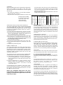
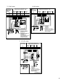
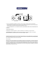
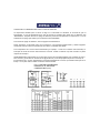
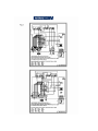
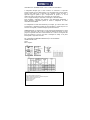
When assembling the sauna unit, follow the dimensions
given in fig. 1. table 1 or the plate on the sauna unit.
The unit is attached to the wall with the screws supplied
with the unit.
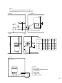
- The unit may be installed in a recess with a minimum
height of 1900 mm. See fig.2
- Only one sauna unit may be installed in a sauna room.
PROTECTIVE RAILING
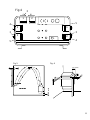
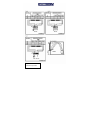
If a protective rail is built
round the sauna unit,
please follow the
instructions in fig 6.
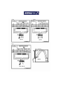
SWITCHING FOR LEFT OR RIGHT CONTROLS
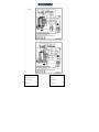
The unit is supplied with a timer and thermostat installed
on the front of the unit, see fig 3. If it is necessary to
move the controls to the right or to the left, this should
be done by an qualified electrician when the sauna is
installed (see fig. 4).
1. Turn the sauna unit upside down, remove the plate.
2. Remove the knobs (3) for the thermostat (2) and the
timer (1) by pulling them straight out.3. Remove the
screws holding the timer and thermostat.
4. Remove the sectional plate from the side of the unit.
5. Move the timer (1) and the thermostat (2) to the side.
The dial plate (5) separately packed is mounted using
the thermostat and timer mounting screws.
6. Press the knobs into place.
7. Replace the sectional plate on the front of the unit.
8. Check that all the wiring to the thermostat and timer
is intact.
9. Replace the junction box plate.
MAINS CONNECTION
The sauna unit must be connected to the power supply
by a qualified electrician and in compliance with current
regulations. The unit is connected to the power supply
using suitable cable (see table above) with REVE (or
equivalent) rubber sheathed mains lead for the final
connection in the sauna.
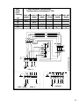
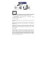
The junction box in the sauna unit is also equipped with
a terminal block which allows the following functions:
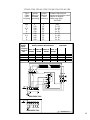
a) Indicator light outside the sauna room (blocks 7 och
8, see circuit diagram, fig. 7). A lead is used with the
same sectional areas as the cable to the sauna unit
(see table).
b) Electricial interlocking of another electricial device
(blocks 9 and 19, see circuit diagram 7). A lead with
a sectioal area of 1,5mm2 (6 A fuse) is used to
connect this device.
A connection box, to be mounted in the sauna room,
must be splash tight and have a condensation moisture
hole, 7 mm. The centre of this box must be not more
than 500 mm above the floor.
NOTE: The overheating safety device may have
been tripped by jolting in transport. It is reset by
pushing a screwdriver through the hole in the front
of the unit, see fig. 3.
- The wall behind the unit may not be clad with Eternit.
asbestos board or similar material. This type of clading
can cause the temperature of the wall material to rise
above the permitted level.
- Wood panelling is the approved material for walls and
ceiling in the sauna room.
Power
Sauna room
Minimum distance
Volume Height Side- Dist. to shelf Ceilwall over 500 mm ing
above floor
Connection HO7RN-F
Floor 230V3~ 230V2~ 400V3N~
kW
m3
mm
mm
mm
mm
mm
mm2
mm2
mm2
3,0
4,5
6,0
8,0
9,0
2-4
3-6
5-9
8 - 13
9 - 14
1900
1900
1900
1900
1900
30
50
70
100
100
50
80
100
150
150
1200
1200
1250
1250
1250
120
120
120
120
120
4 x 2,5
4 x 2,5
4x4
4x6
4x6
3x2,5
3x4
5x1,5
5x1,5
5x1,5
5x2,5
5x2,5
SAUNA STONES
Since they may be dusty, we recommend that they are
rinced before being placed in the rock compartement.
Put the largest stones at the bottom. Do not pack the
stones tight but place them to allow good air circulation.
toprevent damage to the sauna unit, the stones must be
replaced if they bein to flake. The diameter of the stones
is 3 - 8cm
TEMPERATURE CONTROL
The thermostat control (fig. 3 ) is set to the desired
temperature. The sauna will reach the sesired temperature in 30-60 minutes, depending on the size of the
sauna room. The three steps thermostat ensures even,
pleasant heat in the saun room.
OVERHEATING PROTECTION
If for any reason the air temperature exceeds acceptable limits, the overheating protection automatically
cuts off the power supply. After about 5 minutes the
power can be put on again by pressing the reset button
(see fig. 3 point 3). Before pressing the reset button, the
possible cause of overheating should be invesigated.
THE TIMER
The timer, which is the main power switch of the sauna
unit, automatically shuts off the unit at the desired time.
8 + 4 hour preselection timer settings
The preselector timer allows between 1 and 8 hours
presetting, and the maximum running time is alw ays 4
hours.
The preselector timer may be used to set in advances
the time when the sauna is to start: if you want to use
the sauna " at once ", the switch is set anywhere
between 1 and 4 hours, and the unit is on.
VENTILATION
To make the sauna bath as pleasant and healthy as
possible, the sauna room must be correctly ventilated.
Incoming air should, if possible, be led in thorugh a vent
immediately under the sauna unit. This vent should be
at least 6 cm, in diameter (see fig. 5).
The exhaust air should, if possible, be led out from the
opposite wall, preferably as far as possible from the incoming air vent. The exhaust air vent should be twice
the size of the incoming air vent, and be located as high
as possible off the floor.
31