1
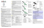
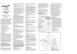
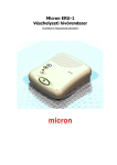
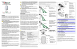
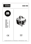
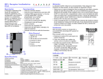
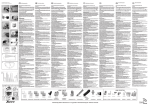
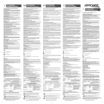
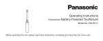
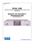
OMNPMD75-TI02
PRINTED IN CANADA 11/2003
OMN-PMD75
Powering the Detector
1. Insert three “AAA” batteries into the battery holder while verifying polarity (figure 4).
2. Insert the battery holder into the back cover and affix the battery connector to the
PCB (see “A1” and “A2” in figure 4).
After connecting the battery connector, a power-up sequence will begin
(lasting 10 to 30 seconds). During this time, the red LED will flash and the
detector will not detect an open zone or tamper.
Replacing Batteries
780 Industriel Blvd., Saint-Eustache (Quebec) J7R 5V3 CANADA
Tel.:(450)491-7444
Fax: (450)491-2313
www.paradox.ca
At the recommended height of 2.1m (7ft) ±10%, the OMN-PMD75 motion detectors
provide full coverage from 1.5m (5ft) to 11m (35ft). The installation height is measured
from the center of the detector (figure 1). All measurements shown in figures are
expressed in meters and (feet).
Avoid bending, cutting or altering the antenna or mounting the detector near or
on metal as this may affect signal transmission.
Avoid placing the detector within proximity of the following sources of interference:
reflective surfaces, direct air flow from vents, fans, windows, sources of steam/oil
vapor, infrared light sources and objects causing temperature changes such as
heaters, refrigerators and ovens.
Do not touch the sensor surface as this could result in a detector malfunction. If
necessary, clean the sensor surface using a soft cloth with pure alcohol.
PCB Height Adjustment
The OMN-PMD75 is designed for optimal performance at a height of 2.1m (7ft), but
can be installed lower or higher. After you have installed the detector, ensure that the
adjustable height markings on the right side of the PCB matches the tab inside the
back cover (see “H” in figure 4 ).
For example, if the detector is installed at a height of 2.1m (7ft), the PCB should then
be adjusted to 2.1m (7ft) (figure 1). Align the desired marking (height) with the back
cover’s plastic tab.
If another installation height is called for, readjust the PCB accordingly. Any PCB
adjustments should be followed by a walk-test of the protected area. Walk-testing
verifies that the required coverage is in place.
LED Setting (J5)
This setting enables or disables the red LED (table 1). The red LED will illuminate for a
period of 4 seconds to indicate detected movement. The motion detector performs a
battery test every 12 hours. If the battery voltage is too low, the red LED will flash at 5second intervals and the motion detector will send a low battery signal to the Omnia
module. The Omnia module then sends the signal to the control panel, which will
generate a trouble and can transmit the signal to the monitoring station. The red LED
will flash rapidly when the motion detector transmits a signal to the Omnia module.
Digital Shield™ Setting (J4)
In Normal Shield mode, the detector is set for normal environments. In High Shield
mode, the detector is set for high-risk environments (potential interferences) and
therefore provides greatly increased false alarm immunity. However, response time
and detector speed may be slower. Refer to table 1.
Single or Dual Edge Processing (J3)
This setting determines the DSP (Digital Signal Processing) operational mode of the
detector. Single Edge Processing mode should be used in normal environments with
minimal sources of interference. Dual Edge Processing mode provides better false
alarm rejection in the case where the detector is placed near sources of interference
that can adversely affect the motion detector. Refer to table 1.
Check-in Supervision Timer (J1, J2)
These two jumpers set the time interval at which the motion detector will communicate
a check-in signal. Refer to table 1.
C
2.1m
(7ft)
B
- anti-tamper switch
- szabotázskapcsoló
- interruptor antisabotaje
E
J5
J4
J3 J2 J1
C
- PCB height markings
- az alaplap magasságállítás jelzései
- marcas de altura de PCI
F
Walk-testing
Open the cover in order to trigger the anti-tamper switch, then snap the cover back
into position. This will activate the motion detector’s walk-test mode for 3 minutes.
At 20°C (68°F), in Normal Shield (J4 = ON) mode and Single Edge Processing mode
(J3 = ON), you should not be able to cross more than one complete zone (consisting
of 2 beams, left and right sensor detecting elements) in the coverage area with any
kind of movement; slow/fast walking or running.
2.1m
(7ft)
In High Shield mode, the amount of movement required to generate an alarm is doubled.
The approximate width of a full beam at 11m (35ft) from the detector is 1.8m (6ft). When
walk-testing, always move across the detection path and not toward the detector.
English
B
A
- optimum beam dispersion
- optimális sugár szóródás
- dispersión de haz óptima
A
A1, A2
- battery connector
- elem csatlakozó
- conector de batería
A1
D
Figure/Ábra 1
1. Disconnect the battery connector from the PCB. Remove the battery holder and
remove the old batteries.
2. Press and release the anti-tamper switch to ensure that the unit has powered down.
3. Follow the steps outlined in “Powering the Detector”.
Telepítési útmutató
English, Magyar, Español
Figure/Ábra 4
Warranty
The Seller warrants its products to be free from defects in materials and workmanship under normal use for a period
of one year. Except as specifically stated herein, all express or implied warranties whatsoever, statutory or
otherwise, including without limitation, any implied warranty of merchantability and fitness for a particular purpose,
are expressly excluded. Because Seller does not install or connect the products and because the products may be
used in conjunction with products not manufactured by the Seller. Seller cannot guarantee the performance of the
security system. Seller obligation and liability under this warranty is expressly limited to repairing or replacing, at
Seller’s option, any products not meeting the specifications. In no event shall the Seller be liable to the buyer or any
other person for any losses or damages whether direct or indirect or consequential or incidental, including without
limitation, any damages for lost profits stolen goods, or claims by any other party, caused by defective goods or
otherwise arising from the improper, incorrect or otherwise faulty installation or use of the merchandise sold.
3.1m
(10ft)
2.1m
(7ft)
C
- unit aims further, the gap between
beams is wider. Pet immunity is
compromised.
C
Alive Software
If the motion detector transmits 2 alarm signals (LED on for 4 sec.) within a 5-minute
period, the detector falls into Energy Save mode where it won’t transmit any alarm
signals for approximately 3 minutes. Due to the motion detector’s Alive Software, the red
LED continues to flash to indicate a detection even when in Energy Save mode. Once
the 3-minute Energy Save mode ends, the motion detector returns to normal operation.
If the detector’s cover is removed and then replaced while in Energy Save
mode, the first detection will trigger an alarm signal.
- minél távolabbi a fókusz, a
távolság a sugarak között annál
nagyobb. A kisállat immunitás
növekszik.
1.1m
(4ft)
2.1m
(7ft)
- el objetivo de la unidad está más
lejos, la distancia entre haces es
mayor. La inmunidad contra
mascotas está comprometida.
Technical Specifications
Sensor Type
Coverage - 90° (standard)
Pet Immunity
Detector Speed
Installation Height
Operating Temperature
two dual opposed infrared sensors
11m x 11m (35ft x 35ft)
up to 40kg (90lbs)
0.2m to 3.5m/sec. (0.6ft to 11.5ft/sec.)
2.1m to 2.7m (7ft to 9ft)
0°C to +50°C (+32°F to +122°F)
RF Frequency
Lens
Power
Transmitter Range
Anti-Tamper Switch
Battery Life †
433* or 868**MHz
2nd generation Fresnel lens, LODIFF®, segments
3 X “AAA” alkaline batteries
150m (500ft)
yes
Lowest check-in setting: 3 years
Highest check-in setting: 1.5 years
2.1m
(7ft)
H
- PCB height tab
- alaplap távtartó fül
- lengüeta de altura de PCI
- top battery
- elem felül nézetbõl
- batería de arriba
Table/Táblázat/Tabla 1
LED Indicator/Indikátor LED/Indicador LED
J5
OFF = disabled/kikapcsolt/deshabilitado
ON = enabled/bekapcsolt/habilitado U
Digital Shield (sensitivity)
Digitális pajzs (érzékenység)
Digital Shield (sensibilidad)
J4
OFF = High Shield (low sensitivity)
Magas pajzs (alacsony érzékenység)
Blindaje Superior (baja sensibilidad)
ON = Normal Shield (high sensitivity)
Normál pajzs (magas érzékenység)
Blindaje Normal (alta sensibilidad) U
Processing Type/Feldolgozás típus/Tipo de Procesamiento
0m 1.5m 3m
6m
(0ft) (5ft) (10ft) (20ft)
9m
(30ft)
11m
(35ft)
J3
OFF = Dual edge/dupla szélsõérték/polaridad doble
ON = Single edge/szimpla/polaridad simple U
Check-in Supervision Timer
Bejelentkezés felügyelet idõzítés
Tiempo de Verificación de Prescencia
3m 1.5m 0m 1.5m 3m
(10ft) (5ft) (0ft) (5ft) (10ft)
J2
OFF = minutes/perc/minutos
ON = hours/óra/horas U
J1
OFF = 6
ON = 12 U
Figure/Ábra 3
A
- corner mount
- sarokba szereléshez
- montaje en esquina
B
12min
6hr
12hr
B
C
Changes or modifications on equipment not expressly approved by Paradox Security Systems could void the
user’s authority to operate the equipment.
A
A
B
6min
B
- flat surface mount
- síkfelületi szereléshez
A
A
compliant to all EU and EFTA countries except Greece according to RTT&E directives.
† Battery life expectancy will vary according to the check-in time interval and the amount of traffic (movement)
the detector has processed. A higher check-in time interval and higher traffic will lower battery life.
© 2002-2003 Paradox Security Systems Ltd. All rights reserved. Specifications may change without prior notice.
One or more of the following US patents may apply: 6215399, 6111256, 5751803, 5721542, 5287111, 5119069,
5077549, 5920259, 5886632. Canadian and international patents may also apply. LODIFF® lens: patent
#4,787,722 (U.S.). Omnia and Shield are trademarks or registered trademarks of Paradox Security Systems Ltd.
or its affiliates in Canada, the United States and/or other countries. LODIFF® is a registered trademark of Fresnel
Technologies Inc.
F
- LED/LED/LED
G
- battery holder
- elemtartó
- compartimiento de batería
Figure/Ábra 2
90°
* FCC ID: KDYOMNPMD75 Canada: 2438A-OMNPMD75
The OMN-PMD75 complies with part 15 of the FCC rules. Operation is subject to the following two conditions:
(1) This device may not cause harmful interference, and (2) This device must accept any interference
received, including interference that may cause undesired operation.
** 868MHz (only)
H
- el objetivo de la unidad está más
cerca; la distancia entre los haces
es más pequeña. La inmunidad
contra mascotas está
comprometida.
Signal Strength Test
In order to verify the receiver's reception of the motion detector’s signal, perform a
signal strength test before finalizing the installation of the motion detector. Prior to
performing the test, make sure the batteries have been inserted into the battery holder
to power the detector. Also verify that the motion detector has been assigned to a
zone. For more information on signal strength tests and zone programming, refer to
the appropriate receiver’s Reference and Installation Manual. If the transmission is
weak, relocating the transmitter by a few inches can greatly improve the reception.
E
- sensors/szenzorok
G
- minél közelebbi a fókusz, a
távolság a sugarak között annál
nagyobb. A kisállat immunitás
csökken.
B
Walk-test mode is also activated for 3 minutes once the motion detector is
powered on.
D
- antenna/antenne/antena
A2
B
- unit aims closer, the gap
between beams is smaller. Pet
immunity is compromised.
- montaje en superficie
plana
U= default/alapértelmezett/de fábrica
C
- PCB height tab
- alaplap magasság
állító fül
After changing the jumper settings, snap on the cover to close the anti-tamper switch
or press and release the anti-tamper switch in order to save the changes.
- lengüeta de altura de
PCI
Después de cambiar la configuración de los puentes, encaje la cubierta en su lugar
para cerrar el interruptor antisabotaje o pulse y suelte el interruptor anti-sabotaje para
guardar los cambios.
B
A jumper beállítások változtatása után, pattintsa vissza a burkolatot a szabotázskapcsoló
zárásához, vagy nyomja le, majd engedje el a szabotázskapcsolót a beállítás mentéséhez.
Magyar
Séta teszt
Español
Àz OMN-PMD75 mozgásérzékelõ a javasolt telepítési magasságban (2,1m+/-10%)
teljes lefedettséget biztosít 1,5m és 11m között. Az elhelyezési magasságot az
érzékelõ közepétõl mérjük (1. ábra). Az ábrán szereplõ távolságok méterben és
lábban értendõk.
Nyissa fel a burkolatot, hogy a szabotázskapcsoló mûködésbe lépjen, majd csukja vissza
a fedelet. Így aktiválható a mozgásérzékelõ Séta teszt módja 3 percre.
20 °C-on (68 °F),normál pajzssal (J4 = ON) és Szimpla szélsõérték feldolgozás módban
(J3 = ON), un humain ne devrait pas pouvoir traverser plus d’une zone
complète (consistant en 2 faisceaux, détecteurs gauche et droit du capteur) dans la zone de
couverture, et ce, peu importe le mouvement effectué : marche lente/rapide ou course.
Instalados a la altura recomendada de 2.1 m (7ft) ±10%, los detectores OMN-PMD75
brindan una cobertura total desde 1.5 m (5ft) hasta 11 m (35ft). La altura de instalación
se calcula desde el centro del detector (figura 1 en la página 1). Todas las medidas en
las figuras están en metros y pies (ft).
Kerülje az antenna hajlítását, vágását vagy változtatását, illetve ne telepítse
az érzékelõt fémre vagy annak közelébe, mert befolyással lehet
a jel érzékelésre.
A következõ interferencia források közelébe lehetõleg ne telepítse az érzékelõt:
tükrözõdõ felületek, ventillátorok közvetlen légárama, ventillátor, ablakok, víz/olajgõz,
infravörös fényforrások és hõmérsékletváltozást elõidézõ berendezések, mint például
fûtõtestek, hûtõszekrény és sütõ.
Ne érintese a szenzor felületét, mert az érzékelõ meghibásodását okozhatja.
Ha feltétlenül szükséges, puha ruhával és tiszta szesszel isztítsa meg az
érzékelõ felületét.
Alaplap magasság állítás
Az OMN-PMD75 optimális teljesítményét 2,1m magasra telepítve nyújtja, de magasabbra
és alacsonyabbra is telepíthetõ. Az érzékelõ felhelyezése után, az alaplap jobb oldalán lévõ
magasság jelõléseknek egyezniük kell a hátlap belsejében található füllel (4. ábra "H" az 1.
oldalon).
Például, ha az érzékelõ 2,1m magasra lett telepítve, az alaplapot a 2,1m jelöléshez kell
állítani (1. ábra). A hátlap mûanyag fülével állíthatja a megfelelõ magasságot (jelölést).
Ha változtatni kell az elhelyezés magasságán, megfelelõen állítsa utána az alaplapot.
Minden alaplap állítást séta teszt kövessen a védett területen. A séta teszttel ellenõrizheti a szükséges lefedettséget.
LED beállítás (J5)
Ezzel a beállítással a piros LED-et lehet ki- és bekapcsolni (1. táblázat). A piros LED 4 másodpercig
világít, ha mozgást érzékel. A mozgásérzékelõ 12 óránként elemtesztet végez. Ha túl
alacsony az elem feszültség, a piros LED 5 másodpercenként felvillan és a mozgásérzékelõ
gyenge elem jelzést küld az Omnia vevõnek. Az Omnia továbbküldi a jelet a központnak,
mely hibát generál és jelzést küld a távfelügyeletnek. A piros LED gyorsan villog amikor a
mozgásérzékelõ jelzést küld az Omnia vevõnek.
Digitális Pajzs™ algoritmus (J4)
Normál pajzs módban, az érzékelõ normál környezetben mûködik megfelelõen. Magas
pajzs módban, az érzékelõ nagy kockázatú környezetben (potenciális zavarok) nyújt
nagyobb vakriasztás szûrést. Bár, ez a reagálási idõt növeli és az érzékelés sebességét
csökkenti. Lásd 1. táblázat.
Szimpla és Dupla szélsõérték feldolgozás (J3)
Ez a beállítás az érzékelõ Digitális jelfeldolgozás (DSP) mûködési módját határozza meg.
A Szimpla szélsõérték feldolgozás normál környezetben minimális interferencia esetén
nyújthat jobb megoldást. A Dupla szélsõérték feldolgozás jobb vakriasztás szûrést biztosít
akkor is, amikor az érzékelõ olyan zavar források közelében lett elhelyezve, melyek károsan
hatnak a mozgásérzékelõ mûködésének hatékonyságára. 1. táblázat.
Jelenlét felügyelet (J1, J2)
Ez a két jumper állítja be milyen idõintervallumban küldje az érzékelõ a vevõnek a
jelenlét jelzést. 1. táblázat.
Üzembehelyezés
1. Tegyen három darab « AAA » elemet az elemtartóba, figyelve a helyes polaritásra (4. ábra).
2. Tegye az elemtartót a hátlapon lévõ helyére, és csatlakoztassa az alaplapra
(« A1 » és « A2 » a 4. ábrán).
Miután csatlakoztatta az elemet, az érzékelõ 10-30 másodperc alatt éled
fel. Ezalatt, a piros LED villog és az érzékelõ nem érzékeli még a nyitott
zónát és a szabotázst.
Elemcsere
1. Húzza le a csatlakozót az alaplapról. Vegye ki az elemtartót és vegye
ki a régi elemeket belõle.
2. Nyomja le, majd engedje el a szabotázskapcsolót, hogy biztosan ne legyen
feszültség a berendezésben.
3. Kövesse az "Üzembehelyezés" szakasz lépéseit.
En mode de protection élevée, la quantité de mouvement nécessaire à la génération
d’une alarme est doublée. La largeur approximative d’un faisceau maximal à 11,0 m
(35 pi) du détecteur est de 1,8 m (6 pi). Lors de l’essai de marche, toujours marcher
d’un côté à l’autre de la trajectoire de détection et non en direction du détecteur.
Le mode d’essai de marche est aussi activé pour 3 minutes une fois que le
détecteur de mouvement est mis en marche.
Test de puissance du signal
Avant de finaliser l’installation du détecteur de mouvement, afin de vérifier si le
récepteur reçoit bien le signal du détecteur, effectuer un test de puissance du signal.
Avant d’effectuer le test, s’assurer que les piles aient été insérées dans le porte-piles
pour alimenter le détecteur. Vérifier aussi que le détecteur de mouvement ait été
assigné à une zone. Pour plus amples renseignements sur les tests de puissance du
signal et la programmation de zone, se réréfer au Manuel d’installation et de référence
du récepteur approprié. Si la transmission est mauvaise, le fait de déplacer l’émetteur
de quelques pouces peut sensiblement améliorer la réception.
Logiciel Alive
Si le détecteur de mouvement transmet 2 signaux d’alarme (DEL allumée pendant 4
secondes) en moins de 5 minutes, il bascule en mode d’économie d’énergie où il n’émet
aucun signal d’alarme pendant environ 3 minutes. Grâce au logiciel Alive du détecteur
de mouvement, la DEL rouge continue de clignoter pour indiquer une détection même
en mode d’économie d’énergie. Lorsque le mode d’économie d’énergie de 3 minutes
prend fin, le détecteur de mouvement retourne à son fonctionnement normal.
Si le couvercle du détecteur est retiré puis remplacé en mode d’économie
d’énergie, la première détection déclenche un signal d’alarme.
Spécifications techniques
Type de capteur
Couverture - 90° (standard)
Insensibilité aux animaux
Vitesse du détecteur
Hauteur d’installation
Température de
fonctionnement
2 capteurs infrarouges à élément opposé double
11 m X 11 m (35 pi X 35 pi)
jusqu’à 40 kg (90 lbs)
0,2 à 3,5 m/sec. (0,6 à 11,5 pi/sec.)
2,1 m à 2,7 m (7 pi à 9 pi)
0 °C à +50 °C (+32 °F à +122 °F)
Fréquence RF
Lentille
433* ou 868** MHz
Alimentation
Portée de l’émetteur
Interrupteur de sécurité
Durée de vie des piles †
lentille Fresnel 2ième génération, LODIFF®, faisceaux
3 piles alcalines « AAA »
150 m (500 pi)
oui
réglage de présence faible : 3 ans
réglage de présence élevé : 1½ ans
* FCC ID : KDYOMNPMD75 Canada : 2438A-OMNPMD75
L’OMN-PMD75 est conforme à la partie 15 des règles FCC. L’application est subordonnée aux deux
conditions suivantes : (1) Ce dispositif ne devrait pas entraîner de brouillage préjudiciable et (2) Ce système
doit accepter toute interférence reçue, y compris les types d’interférences pouvant entraîner un
fonctionnement indésirable.
** 868 MHz (seulement)
Conforme à tous les pays de l’UE et de l’EFTA sauf la Grèce d’après la
directive européenne R&TTE.
† La durée de vie de la pile varie selon l'intervalle de temps de supervision de présence et selon la quantité de
mouvement traité par le détecteur. Un grand intervalle de temps de supervision de présence et une grande
quantité de détection de mouvement réduisent la durée de vie de la pile.
Tout changement ou toute modification du matériel n’étant pas formellement approuvé(e) par Systèmes de
sécurité Paradox peut annuler l’autorisation accordée à l’utilisateur de se servir du système.
© Systèmes de sécurité Paradox Ltée, 2002-2003. Tous droits réservés. Spécifications sujettes à changement sans
préavis. Un ou plusieurs des brevets américains suivants peuvent s’appliquer : 6215399, 6111256, 5751803,
5721542, 5287111, 5119069, 5077549, 5920259 et 5886632. Des brevets canadiens et internationaux peuvent aussi
s’appliquer. Lentille LODIFF® : brevet # 4, 787, 722 (É.-U.). Omnia et Shield sont des marques de commerce ou des
marques de commerce déposées de Systèmes de sécurité Paradox Ltée ou de ses sociétés affiliées au Canada, aux
États-Unis et/ou dans d’autres pays. LODIFF® est une marque de commerce déposée de Fresnel Technologies Inc.
Garantie
Le Vendeur garantie, pour une période d’un an, que ses produits ne comportent aucun défaut de pièce ou de maind’œuvre si utilisés dans des conditions normales. Sauf ce qui est expressément prévu par les présentes, toute autre
garantie, expresse ou implicite, légale ou autre, se rapportant à la qualité de la marchandise y compris, sans limiter ce
qui précède, toute garantie implicite de qualité marchande et d’adaptation à des fins particulières est exclue. Le
Vendeur ne peut garantir la performance du système de sécurité parce qu’il n’installe pas et ne raccorde pas les
produits et parce que les produits peuvent être utilisés conjointement avec des produits qui ne sont pas fabriqués par
le Vendeur. L’obligation et la responsabilité du Vendeur en vertu de la présente garantie sont expressément limitées à
la réparation ou au remplacement, au choix du Vendeur, de tout produit ne rencontrant pas les spécifications. Dans
tous les cas, le Vendeur ne sera pas tenu responsable, envers l’acheteur ou toute autre personne, de pertes ou de
dommages de quelque sorte, directs ou indirects, conséquents ou accidentels, y compris, sans limiter ce qui précède,
de pertes de profits, de biens volés ou de réclamations par des tiers causés par des produits défectueux ou autre
résultant d’une installation ou d’un usage impropre, incorrect ou autre de la marchandise vendue.
Evite doblar, cortar o alterar la antena o montar el detector cerca de o sobre
metal pues esto puede afectar la transmisión de la señal.
No ubique el detector cerca de las siguientes fuentes de interferencia: superficies
reflectantes, corrientes de aire provenientes de sistemas de ventilación, ventiladores,
ventanas, fuentes de vapor de agua / humo de aceite, fuentes de luces infrarrojas y
objetos que provoquen cambios de temperatura como aparatos de calefacción,
refrigeradores y hornos.
No toque la superficie del sensor pues puede provocar un mal funcionamiento
del detector. De ser necesario, limpie la superficie del sensor con un paño
delicado y alcohol puro.
Ajuste de la Altura de la Placa de Circuito Impreso (PCI)
El OMN-PMD75 está diseñado para funcionar de manera óptima a la altura de 2.1m
(7ft), pero puede ser instalado a mayor o menor altura. Luego de haber instalado el
detector, asegúrese que las marcas de ajuste de altura al lado derecho de la PCI
coinciden con la lengüeta al interior de la cubierta trasera (ver “H” en la figura 4).
Por ejemplo, si el detector es instalado a una altura de 2.1m (7ft), la PCI debe
entonces ser ajustada a 2.1m (7ft) (figura 1 en la página 1). Alinee la marca de altura
deseada con la lengüeta plástica de la cubierta trasera.
De ser necesaria otra altura de instalación, reajuste la PCI en consecuencia. Todo
ajuste efectuado a la PCI debe ser seguido de una prueba caminando en el área
protegida. La prueba-caminando sirve para verificar si se tiene la cobertura deseada.
Configuración de la luz LED (J5)
Esta configuración sirve para habilitar o deshabilitar la luz LED roja (tabla 1). La luz
LED roja se enciende durante 4 segundos para indicar la detección de un movimiento.
El detector de movimiento efectúa una prueba de batería cada 12 horas. Si el voltaje
de la batería es muy bajo, la luz LED roja parpadeará a intervalos de 5 segundos y el
detector de movimiento enviará una señal de batería baja al módulo Omnia. El
módulo Omnia enviará entonces la señal a la central, la cual generará un fallo y podrá
transmitir la señal a la receptora. La luz LED roja parpadeará rápidamente cuando el
detector de movimiento transmita una señal al módulo Omnia (tabla 1 en la página 1).
Configuración del Blindaje Digital Shield™ (J4)
En el modo Blindaje Normal, el detector está configurado para ambientes normales.
En el modo de Blindaje Superior, el detector está configurado para ambientes de alto
riesgo (interferencias potenciales) y por consiguiente brinda una inmunidad
acrecentada contra las falsas alarmas. Sin embargo, el tiempo de respuesta y la
velocidad del detector podrían ser más lentos. Consulte la tabla 1.
Procesamiento de Polaridad Simple o Doble (J3)
Esta configuración determina el modo de funcionamiento de Procesamiento Digital de
Señales del detector. El Procesamiento de Polaridad Simple debe ser usado en
ambientes normales con mínimas fuentes de interferencia. El Procesamiento de Polaridad
Doble ofrece un mayor rechazo a las falsas alarmas si el detector está ubicado cerca de
fuentes de interferencia que pueden afectarlo negativamente. Consulte la tabla 1.
atravesar más de una zona completa (que consiste de 2 haces, elementos de
detección izquierdo y derecho del sensor) en el área de cobertura con cualquier tipo
de movimiento; caminando despacio/rápido o corriendo.
En el modo de Blindaje Superior se requiere el doble de la cantidad de movimiento
para generar una alarma. El ancho aproximado de un haz completo a 11 m (35ft) del
detector es de 1.8 m (6ft). Al efectuar la prueba caminado, muévase siempre
atravesando la trayectoria de detección, no hacia el detector.
El modo de prueba caminando también se activa por 3 minutos cuando se
enciende el detector de movimiento.
Prueba de Fuerza de la Señal
Para verificar si el receptor está recibiendo la señal del detector de movimiento,
efectúe una prueba de fuerza de señal antes de terminar la instalación del detector de
movimiento. Antes de realizar la prueba, asegúrese que las baterías fueron
insertadas en su compartimiento para poder encender el detector. Compruebe
también que el detector de movimiento esté asignado a una zona. Para más
información acerca de las pruebas de fuerza de señal y la programación de zonas,
consulte el Manual de Instalación y Consulta del receptor utilizado. Si la transmisión
es débil, el mover el transmisor tan sólo unos pocos centímetros puede mejorar
considerablemente la recepción.
Software Alive
Si el detector de movimiento transmite 2 señales de alarma (LED iluminado por 4
seg.) al interior de 5-minutos, el detector entrará en el Modo de Ahorro de Energía
durante el cual no transmitirá ninguna señal de alarma durante aproximadamente 3
minutos. Debido al Software Alive del detector de movimiento, la luz LED roja seguirá
parpadeando para indicar la detección incluso cuando esté en el Modo de Ahorro de
Energía. Cuando terminen los 3 minutos del Modo de Ahorro de Energía, el detector
de movimiento retoma su funcionamiento normal.
Si la cubierta del detector es quitada y repuesta durante el Modo de Ahorro de
Energía, la primera detección activará una señal de alarma.
Especificaciones Técnicas
Tipo de Sensor
Cobertura - 90° (estándar)
Inmunidad a Mascotas
Velocidad de Respuesta de Detector
Altura de Instalación
Temp. de Funcionamiento
dos sensores infrarrojos de doble oposición
11m x 11m (35ft x 35ft)
de hasta 40kg (90lbs)
0.2m a 3.5m/seg (0.6ft a 11.5ft/seg)
2.1m a 2.7m (7ft a 9ft)
0°C a +50°C (+32°F a +122°F)
Radiofrecuencia
Lentes
433* ó 868**MHz
lentes Fresnel de 2da generación, LODIFF®,
segmentos
3 Baterías alcalinas “AAA”
150m (500ft)
sí
Verificación menos frecuente 3 años
Verificación más frecuente 1.5 años
Alimentación
Alcance del Transmisor
Interruptor Antisabotaje
Vida Útil de la Batería†
* FCC ID: KDYOMNPMD75 Canada: 2438A-OMNPMD75
Este dispositivo cumple con la sección 15 de los reglamentos de la FCC. Su operación está sujeta a las
siguientes condiciones: (1) Este dispositivo no debe causar severa interferencia y (2) Este dispositivo debe
aceptar cualquier interferencia recibida, incluyendo las interferencias que puedan provocar un funcionamiento
errático.
Tiempo de Verificación de Presencia (J1, J2)
Estos dos puentes establecen el intervalo de tiempo en el que el detector de
movimiento transmitirá una señal de presencia. Consulte la tabla 1.
Encendido del Detector
1. Ponga tres baterías “AAA” en su compartimiento verificando la polaridad (figura 4
en la página 1).
2. Ponga el compartimiento de baterías dentro de la cubierta trasera y enchufe el
conector de batería en la PCI (vea “A1” y “A2” en la figura 4).
Luego de haber enchufado el conector de batería, empezará una
secuencia de encendido (que durará de 10 a 30 segundos). Durante este
tiempo, la luz LED roja parpadeará y el detector no detectará zonas
abiertas ni sabotajes.
Cambio de Baterías
1. Desenchufe el conector de batería de la PCI. Quite el compartimiento de baterías y
saque las baterías gastadas.
2. Pulse y suelte el interruptor antisabotaje para asegurarse que la unidad fue apagada.
3. Siga los pasos indicados en “Encendido del Detector”.
Prueba Caminando
Abra la cubierta para activar el interruptor antisabotaje, luego devuélvala a su posición
original. Esta operación activará por 3 minutos el modo de prueba caminando del
detector de movimiento. A 20 °C (68 °F), en los modos de Blindaje Normal (J4 = ON)
y de Procesamiento de Polaridad Simple (J3 = ON), usted no debería ser capaz de
** 868MHz (sólo)
directivas de RTT&E.
cumple con todos los paises de la UE y EFTA excepto Grecia, de acuerdo a las
† La esperanza de vida de la batería puede variar dependiendo del intervalo de verificación de presencia y del
tráfico (cantidad de movimiento) procesado por el detector. Un intervalo de verificación más frecuente y un
mayor tráfico disminuirán la esperanza de vida de la batería.
Todo cambio o modificación que no haya sido claramente aprobado por Paradox Security Systems puede
anular la autorización del usuario para operar este equipo.
© 2002-2003 Paradox Security Systems Ltd. Todos los derechos reservados. Las especificaciones pueden
cambiar sin previo aviso. Una o más de las siguientes patentes EE.UU podría aplicarse: 6215399, 6111256,
5751803, 5721542, 5287111, 5119069, 5077549, 5920259, 5886632. Patentes canadienses e internacionales
también podrían aplicarse. Lentes LODIFF®: patente #4,787,722 (EE.UU). Omnia y Shield son marcas de
comercio o marcas registradas de Paradox Security Systems Ltd. o de sus afiliados en Canadá, Estados Unidos
y/o otros países. LODIFF® es una marca registrada de Fresnel Technologies Inc.
Garantía
El fabricante garantiza que sus productos están libres de defectos, tanto materiales como de mano de obra, bajo
un uso normal durante un año. Exceptuando lo que se menciona aquí específicamente, todas las garantías
expresas o implícitas, sean estatutarias o de otro tipo, cualquier garantía implícita de comerciabilidad y de
adaptabilidad a un propósito particular, son expresamente excluidas. Debido a que el fabricante no instala ni
conecta los productos y debido a que los productos podrían ser usados en conjunto con productos no
manufacturados por el fabricante, el fabricante no puede garantizar el rendimiento del sistema de seguridad. La
obligación del fabricante bajo esta garantía se limita expresamente a la reparación o remplazo, según el vendedor,
de cualquier producto que no cumpla con las especificaciones. En ningún momento podrá el comprador o
cualquier persona hacer responsable al vendedor por cualquier pérdida o daños ocasionados, sean directos o
indirectos, incluyendo, pero sin limitarse a esto, cualquier daño por pérdida de beneficios, mercancía robada o
reclamaciones realizadas por terceros, que sea causado por artículos defectuosos o se deban al uso incorrecto o a
una instalación defectuosas del material.