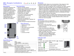
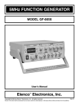
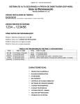
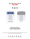
1
ParaDox Digiplex EVO96 – Quick Programming Guide (V1.00) SECTION A: System information * Zone configuration Model DGP-EVO 96 On board zone 8 zones Expander Hardwire APR3-ZX 4 Four (4) zone hardwire APR3-ZX 8 Eight (8) zone hardwire DGP2-50 Addressable PIR (Dual element) DGP2-60 Addressable PIR (Quad element) DGP2-70 Addressable Pet immunity PIR Wireless MG-RCV3 Magellan wireless receiver MG-DCT1 Door transmitter MG-PMD1P Pet immunity PIR (dual element) MG-PMD75 Pet immunity PIR (Dual-Optic) MG-PMD85 OUTDOOR Pet immunity PIR Note: Any combination either hardwire or/and wireless up to 96 zones * System modules DGP-EVO 96 8 zones (16 zones by zone doubling) Hardwire zone APR3-ZX 4 APR3-ZX 8 4 zones 8 zones Addressable zone DGP2-50 Addressable PIR (Dual element) DGP2-60 Addressable PIR (Quad element) DGP2-70 Addressable Pet immunity PIR (Dual –optic) 1 zone 1 zone 1zone Wireless zone MG-RCV3 Magellan wireless receiver (up to 16 transmitters) MG-DCT1 Door transmitter MG-PMD1P Pet immunity PIR (dual element) MG-PMD75 Pet immunity PIR (Dual-Optic) MG-PMD85 OUTDOOR Pet immunity PIR 1 zone 1 zone 1 zone 1 zone Keypad DGP2-641BL LCD (supply with panel) DGP2-648BL LED – 48 zones DGP2-ANC1B Annunciator Accessories APR3-ADM2 In touch voice arm/disarm module APR3-PRT1 Printer module APR3-PGM1 One PGM expansion module APR3-PGM4 Four PGM expansion module 1 * Bus isolator/booster APR3-HUB2 Hub and bus isolator module DGP2-PS17 Power supply module One module has 2 buses Requires 2 DGP2-PS17 for one APR3-HUB2 (each bus one power supply) * Card access DGP-ACM11 Access control module CR-R880-BL CR-R870-A CR-R702-A CR-R704-B Main controller Indoor/outdoor proximity reader Indoor proximity reader Clam shell proximity card Blue proximity key tag *Listen-in module DGP-LSN4 Listen-In Module DGP-SUB1 Listen-in substation (4 units per DGP-LSN4) Main board Substation (for intercom, anauciator) * System features 8 on-board zone, expandable up to 96 [Combination of hardwire modules, addressable zones or wireless zones (max 16 zone)] 8 partitions 999 user codes 2048 events list (via NE ware remote upload/download software) 3 on-board PGM expandable up to 250 Access control up to 32 doors 1.7A switching power supply Supervise bell output Telephone line monitoring Hourly test transmission Call up to 4 phones Arm/disarm and control PGM via phone GuardWall technology / 4-wire bus system supports up to 254 expansion modules, connects modules up to 3000ft (18AWG) / 1000ft (22AWG) from the panel. Specifications Maximum Aux power – 700mA [DGP2-641keypad is 110 mA per unit, APR3-ZX4 is 30 mA, APR3-ZX8 is 30mA, addressable PIR is 30 mA] Wire gauge refers to PAGE 53 of Original Programming Guide 2 SECTION B: Programming To enter Programming Mode: 1. 2. 3. 4. Press and hold the [0] key Enter [000000] (Prg LED flashing for LED keypad and SECTION wording for LCD keypad), you are in the programming mode Enter 4 digits SECTION number (Prg LED light on) Enter required DATA (Either enter 2 digits, 3 digits, 4 digits, 8 digits (for S/N) or ON / OFF relevant key) Press [ENTER] to confirm or [CLEAR] to ignore [0] to [9] = key 0 to 9 respectively [STAY] = A [FORCE] = B [ARM] = C [DISARM] = D [BYP] = E [MEM] = F Remember: After keyed in a required DATA, always press ENTER and CLEAR, in order to let the ENTER key flashing before proceed with entering the next 4 digits SECTION number. Example: The main board is 8 zones, one keypad zone, one 8 zone expander (ZX8) & 2 pcs of PIR. Note: All zones can be assigned to any desired zone number. MUST do step 1 ,2 & 3, or else zone is DISABLE Step 1 – Zone Numbering Press & hold [0], then enter [000000], you are in the programming mode Main board – 8 on board zone: Press section [0001], enter [8 digit S/N, then 3 digit input], means 8 digits is the main board S/N, and key in 001. Press section [0002], enter [8 digit S/N, then 3 digit input], means 8 digits is the main board S/N, and key in 002. Press section [0003], enter [8 digit S/N, then 3 digit input], means 8 digits is the main board S/N, and key in 003. Press section [0004], enter [8 digit S/N, then 3 digit input], means 8 digits is the main board S/N, and key in 004. Press section [0005], enter [8 digit S/N, then 3 digit input], means 8 digits is the main board S/N, and key in 005. Press section [0006], enter [8 digit S/N, then 3 digit input], means 8 digits is the main board S/N, and key in 006. Press section [0007], enter [8 digit S/N, then 3 digit input], means 8 digits is the main board S/N, and key in 007. Press section [0008], enter [8 digit S/N, then 3 digit input], means 8 digits is the main board S/N, and key in 008. Keypad: Press section [0009], enter [8 digit S/N, then 3 digit input], means 8 digits is the keypad S/N, and key in 009. 8 zones Expander board: Press section [0010], enter [8 digit S/N, then 3 digit input], means 8 digits is the expander board S/N, and key in 001. Press section [0011], enter [8 digit S/N, then 3 digit input], means 8 digits is the expander board S/N, and key in 002. Press section [0012], enter [8 digit S/N, then 3 digit input], means 8 digits is the expander board S/N, and key in 003. Press section [0013], enter [8 digit S/N, then 3 digit input], means 8 digits is the expander board S/N, and key in 004. Press section [0014], enter [8 digit S/N, then 3 digit input], means 8 digits is the expander board S/N, and key in 005. Press section [0015], enter [8 digit S/N, then 3 digit input], means 8 digits is the expander board S/N, and key in 006. Press section [0016], enter [8 digit S/N, then 3 digit input], means 8 digits is the expander board S/N, and key in 007.Press section [0017], enter [8 digit S/N, then 3 digit input], means 8 digits is the expander board S/N, and key in 008. 3 PIR: Press section [0018], enter [8 digit S/N], means 8 digits is the PIR S/N. Press section [0019], enter [8 digit S/N], means 8 digits is the PIR S/N. 4 zones Expander board: Press section [0020], enter [8 digit S/N, then 3 digit input], means 8 digits is the expander board S/N, and key in 001. Press section [0021], enter [8 digit S/N, then 3 digit input], means 8 digits is the expander board S/N, and key in 002. Press section [0022], enter [8 digit S/N, then 3 digit input], means 8 digits is the expander board S/N, and key in 003. Press section [0023], enter [8 digit S/N, then 3 digit input], means 8 digits is the expander board S/N, and key in 004. 16 zones Wireless Receiver: Press section [0024], enter [8 digit S/N, then 3 digit input], means 8 digits is the Receiver S/N, and key in 001. Press section [0025], enter [8 digit S/N, then 3 digit input], means 8 digits is the Receiver S/N, and key in 002. Press section [0026], enter [8 digit S/N, then 3 digit input], means 8 digits is the Receiver S/N, and key in 003. Press section [0027], enter [8 digit S/N, then 3 digit input], means 8 digits is the Receiver S/N, and key in 004. Press section [0028], enter [8 digit S/N, then 3 digit input], means 8 digits is the Receiver S/N, and key in 005. Press section [0029], enter [8 digit S/N, then 3 digit input], means 8 digits is the Receiver S/N, and key in 006. Press section [0030], enter [8 digit S/N, then 3 digit input], means 8 digits is the Receiver S/N, and key in 007. Press section [0031], enter [8 digit S/N, then 3 digit input], means 8 digits is the Receiver S/N, and key in 008. Press section [0032], enter [8 digit S/N, then 3 digit input], means 8 digits is the Receiver S/N, and key in 009. Press section [0033], enter [8 digit S/N, then 3 digit input], means 8 digits is the Receiver S/N, and key in 010. Press section [0034], enter [8 digit S/N, then 3 digit input], means 8 digits is the Receiver S/N, and key in 011. Press section [0035], enter [8 digit S/N, then 3 digit input], means 8 digits is the Receiver S/N, and key in 012. Press section [0036], enter [8 digit S/N, then 3 digit input], means 8 digits is the Receiver S/N, and key in 013. Press section [0037], enter [8 digit S/N, then 3 digit input], means 8 digits is the Receiver S/N, and key in 014. Press section [0038], enter [8 digit S/N, then 3 digit input], means 8 digits is the Receiver S/N, and key in 015. Press section [0039], enter [8 digit S/N, then 3 digit input], means 8 digits is the Receiver S/N, and key in 016. Note: Transmitter S/N program in Step 7 D 4 Step 2 – Zone Type, Partition & Options Press & hold [0], then enter [000000], you are in the programming mode Press section [0101], [4,1, ENTER, CLEAR], means ZONE 1 Instant, Partition 1. Press section [0102], [3,1, ENTER, CLEAR], means ZONE 2 follow zone (PIR), Partition 1. Press section [0103], [4,1, ENTER, CLEAR], means ZONE 3 Instant, Partition 1. Press section [0104], [4,1, ENTER, CLEAR], means ZONE 4 Instant, Partition 1. Press section [0105], [4,1, ENTER, CLEAR], means ZONE 5 Instant, Partition 1. Press section [0106], [4,1, ENTER, CLEAR], means ZONE 6 Instant, Partition 1. Press section [0107], [4,1, ENTER, CLEAR], means ZONE 7 Instant, Partition 1. Press section [0108], [4,1, ENTER, CLEAR], means ZONE 8 Instant, Partition 1. Press section [0109], [1,1, ENTER, CLEAR], means ZONE 9 Delay, Partition 1. (Main door / keypad zone) Press section [0110], [4,1, ENTER, CLEAR], means ZONE 10 Instant, Partition 1. Press section [0111], [4,1, ENTER, CLEAR], means ZONE 11 Instant, Partition 1. Press section [0112], [4,1, ENTER, CLEAR], means ZONE 12 Instant, Partition 1. Press section [0113], [4,1, ENTER, CLEAR], means ZONE 13 Instant, Partition 1. Press section [0114], [4,1, ENTER, CLEAR], means ZONE 14 Instant, Partition 1. Press section [0115], [4,1, ENTER, CLEAR], means ZONE 15 Instant, Partition 1. Press section [0116], [4,1, ENTER, CLEAR], means ZONE 16 Instant, Partition 1. Press section [0117], [4,1, ENTER, CLEAR], means ZONE 17 Instant, Partition 1. Press section [0118], [4,1, ENTER, CLEAR], means ZONE 18 Instant, Partition 1. Press section [0119], [4,1, ENTER, CLEAR], means ZONE 19 Instant, Partition 1. Press section [0120], [4,1, ENTER, CLEAR], means ZONE 20 Instant, Partition 1. Press section [0121], [4,1, ENTER, CLEAR], means ZONE 21 Instant, Partition 1. Press section [0122], [4,1, ENTER, CLEAR], means ZONE 22 Instant, Partition 1. Press section [0123], [4,1, ENTER, CLEAR], means ZONE 23 Instant, Partition 1. And [0124] for zone 24, [0125] for zone 25, and so on ……………. Key in section 0101 for zone 1 0102 for zone 2 0103 for zone 3 up to …. 0196 for zone 96 Zone type 0 for zone disable 1 for entry delay 1 3 for follow 4 for Instant 6 for 24 hour [panic] D for fire[24 hour] Partition 1 for partition 1 2 for partition 2 3 for partition 3 4 for partition 4 5 for partition 5 6 for partition 6 7 for partition 7 8 for partition 8 Zone options 1 for auto zone shutdown [default: OFF] 2 for Bypassable zone [default: ON] 3 for stay zone [default: OFF] 4 for force zone [default: OFF] 5 & 6 are OFF for audible zone [default] 5 ON & 6 OFF for silent zone 7 for intellizone [default: OFF] Note 1: The 1st digit represents by: 1 for Delay zone, 3 for Follow zone, 4 for Instant zone, 6 for 24 hour alarm. Don’t program keypad zones if not used. Note 2: If the zone wants to become a STAY zone, instead of [3,1,ENTER, CLEAR], replace it with [3,1 and ON key 3, ENTER, CLEAR], means this zone will be bypassed when stay armed. E.g.: Press section [0102], [3,1, and ON key 3, ENTER, CLEAR], means ZONE 2 follow zone (PIR), Partition 1. If the zone want to become a FORCE zone, instead of [1,1,ENTER, CLEAR]. Replace it with [1,1,and ON key 4, ENTER, CLEAR], means this zone will be allowed open during arming. E.g.: Press section [0109], [1,1, and ON key 4, ENTER, CLEAR], means ZONE 9 Delay, Partition 1. (Main door / keypad zone) Note 3: By default, all zones are Bypassable. 5 Step 3 – Enable EOL (End Of Line resistor) Press & hold [0], then enter [000000], you are in the programming mode Press section [3033], [ON key 7], means used of EOL resistor on hardwire zones Step 4 - Others essential basic features to be programmed Press & hold [0], then enter [000000], you are in the programming mode Section 0961, enter [002], zone 1 on board for 60 ms for vibration sensor Section 0962, enter [002], zone 2 on board for 60 ms for vibration sensor Section 0963, enter [002], zone 3 on board for 60 ms for vibration sensor Section 0964, enter [002], zone 4 on board for 60 ms for vibration sensor Section 0965, enter [002], zone 5 on board for 60 ms for vibration sensor Section 0966, enter [002], zone 6 on board for 60 ms for vibration sensor Section 0967, enter [002], zone 7 on board for 60 ms for vibration sensor Section 0968, enter [002], zone 8 on board for 60 ms for vibration sensor Section 3108 for exit delay partition 1 (e.g.: enter [3108], then key in [030] for 30 seconds). Default is 60 seconds Section 3111 for entry delay partition 1 (e.g.: enter [3111], then key in [030] for 30 seconds). Default is 60 seconds Section 3113 for bell timer partiton 1 (e.g.: enter [234], then key in [010] for 10 minutes). Default is 4 minutes Section 3123, key for keypad Panic option wanted. (e.g: ON 1,2,3,4,5,6 for audible panic [1]&[3], [4]&[6], [7]&[9] ) Section 3125, ON key for option wanted. For one-touch functions. (e.g: ON 1 for regular arming, ON 2 for stay arming, ON 3 for instant arming & ON 4 for force arming) Note: Stay & force arming need to be programmed in Step 2 for each individual zone. Section 3051, key in 008. For number of ring pick up. 6 * Choose either Step 5A or 5B Step 5 A – To call Handphone / Phone Press & hold [0], then enter [000000], you are in the programming mode 1. 2. 3. 4. 5. 6. 7. 8. 9. 10. 11. 12. 13. 14. 15. Section 3036, ON key [3], (key 4 5 & 6 remain ON). To enable Dialer. Section 3036, ON key [1], for telephone line monitoring (trouble on keypad if telephone being cut) Section 3070, enter [7777] for pager reporting format to dial tel. 1,2,3 & 4. Section 3061, enter [8888]. For account no. 1 Section 3062, enter [8888]. For account no. 2 Section 3063, enter [8888]. For account no. 3 Section 3064, enter [8888]. For account no. 4 Section 3071, enter phone no. 1 follow by codes (e.g.: 0121234567 BYP 88 BYP 88 BYP 88 BYP 88 BYP 88 BYP 88 BYP 888). Section 3072, enter phone no. 2 follow by codes (e.g.: 0121234568 BYP 88 BYP 88 BYP 88 BYP 88 BYP 88 BYP 88 BYP 888). Section 3073, enter phone no. 3 follow by codes (e.g.: 0121234569 BYP 88 BYP 88 BYP 88 BYP 88 BYP 88 BYP 88 BYP 888). Section 3074, enter phone no. 4 follow by codes (e.g.: 0121234560 BYP 88 BYP 88 BYP 88 BYP 88 BYP 88 BYP 88 BYP 888). Section 3056, enter [002], number of dial attempt is 2 times Section 0201, key in [33][ENTER][33][ENTER][33]ENTER][33][ENTER][33][ENTER][33]ENTER][33][ENTER][33][ENTER ] For alarm reporting codes zone 1 to 8. Section 0209, [33][ENTER][33][ENTER][33]ENTER][33][ENTER][33][ENTER][33]ENTER][33][ENTER][33][ENTER ] key in For alarm reporting codes zone 9 to 18. Section 0219, [33][ENTER][33][ENTER][33]ENTER][33][ENTER][33][ENTER][33]ENTER][33][ENTER][33][ENTER ] For alarm reporting codes zone 19 to 26. Note: For PABX line: [9] [BYP] [Phone number] Step 5 B – Link To Centre Monitoring Station (CMS) Press & hold [0], then enter [000000], you are in the programming mode Section 3070 3036 3037 3061 3062 3071 3072 3040 3041 4031 Contact I.D [5555] (Do nothing, already in default) ON key [3], (key 4, 5 & 6 remain ON) OFF key [8], for report zone restore on bell cut-off Enter 4 digit account no 1 (Note: account with digit [0 = STAY] key Enter 4 digit account no. 2 (normally same as account no. 1) Enter phone no. 1 (e.g.: 12345678 [ENTER][CLEAR] ) Enter phone no. 2 (e.g.: 12345679 [ENTER][CLEAR] ) Enter [001] for daily auto test Enter [HH:MM] for test time [CLEAR] 7 Step 6 – PGM (Programmable output 1 to 3) Press & hold [0], then enter [000000], you are in the programming mode Option 1 Option 2 Section [0910], enter [010] Section [0911], enter [000] Section [0912], enter [001] Section [0913], enter [255] Section [0914], enter [014] Section [0915], enter [000] Section [0916], enter [001] Section [0917], enter [255] Section [0920], enter [024] Section [0921], enter [255] Section [0922], enter [001] Section [0923], enter [096] Section [0924], enter [020] Section [0925], enter [000] Section [0926], enter [001] Section [0927], enter [255] Arming in regular mode for PGM 1 [Light ON when system arm and OFF system disarm] Strobe for PGM 2 [Strobe stop once key in user codes] For more options, refer to System Programming Outputs page 14. Wiring connection: POSITIVE leg of LED to AUX + and NEGATIVE leg of LED (with 1k resistor) to PGM 1. Note: PGM 1 only support 50mA, a Relay is needed if more than 50mA. PGM 2 and 3 are contact (COM & NO). Step 7: Expansion Modules Programming Guide To enter Programming Mode (it is advisable to use LCD to do this programming): 1. 2. 3. Press and hold the [0] key Enter [000000] (SECTION will be displayed on LCD keypad), you are in the programming mode Enter SECTION [4003] (NOTE: this 4003 is common section applicable for all the expansion modules) Then, choose one of the following expansion module’s serial number 4. 5. 6. Enter 8-digit [Serial number] of the Expansion module Enter 3-digit [SECTION] you wish to program Enter required [DATA] Press [ENTER] to confirm or [CLEAR] to ignore A: LCD keypad (DGP2-641BL) Section [003], ON key [2,3 & 8], to display exit delay, entry delay and time on keypad B: DGP2-648 LED keypads C: Addressable PIR (DGP2-50 / DGP2 – 60 / DGP2 – 70) Section [001], On key 1, for less sensitive Section [002], enter [003], meaning 000 is for very sensitive, 002 normal and 003 less sensitive. (default is 002) 8 D: Magellan Wireless Receiver Module (MG-RCV3) Section [001], On key [1], for low battery supervision st Press section [101], enter [6 digit S/N], means 8 digits is the transmitter S/N. (becomes 1 input of the receiver) nd Press section [102], enter [6 digit S/N], means 8 digits is the transmitter S/N. (becomes 2 input of the receiver) Press section [103], enter [6 digit S/N], means 8 digits is the transmitter S/N. (becomes 3rd input of the receiver) th Press section [104], enter [6 digit S/N], means 8 digits is the transmitter S/N. (becomes 4 input of the receiver) Press section [105], enter [6 digit S/N], means 8 digits is the transmitter S/N. (becomes 5th input of the receiver) th Press section [106], enter [6 digit S/N], means 8 digits is the transmitter S/N. (becomes 6 input of the receiver) th Press section [107], enter [6 digit S/N], means 8 digits is the transmitter S/N. (becomes 7 input of the receiver) th Press section [108], enter [6 digit S/N], means 8 digits is the transmitter S/N. (becomes 8 input of the receiver) Press section [109], enter [6 digit S/N], means 8 digits is the transmitter S/N. (becomes 9th input of the receiver) th Press section [110], enter [6 digit S/N], means 8 digits is the transmitter S/N. (becomes 10 input of the receiver) Press section [111], enter [6 digit S/N], means 8 digits is the transmitter S/N. (becomes 11 th input of the receiver) th Press section [112], enter [6 digit S/N], means 8 digits is the transmitter S/N. (becomes 12 input of the receiver) th Press section [113], enter [6 digit S/N], means 8 digits is the transmitter S/N. (becomes 13 input of the receiver) th Press section [114], enter [6 digit S/N], means 8 digits is the transmitter S/N. (becomes 14 input of the receiver) Press section [115], enter [6 digit S/N], means 8 digits is the transmitter S/N. (becomes 15th input of the receiver) th Press section [116], enter [6 digit S/N], means 8 digits is the transmitter S/N. (becomes 16 input of the receiver) For MG Remote Control Assign Remote to follow panel’s user number Press section [301], enter [3 digit user no.], for remote control 1. Press section [302], enter [3 digit user no.], for remote control 2. …up to [316] for remote control 16. Button assignment (for button A, B, C, D) Press section [401], enter [1,5,7,7], for remote control 1. Press section [402], enter [1,5,7,7], for remote control 2. …up to [416] for remote 16 For Button C activates (ON for 2 seconds) PGM on OMNIA RCV3 Receiver [for example to trigger autogate] Press section [401], enter [1,5,0,7], for remote control 1’s Button C to trigger PGM 3 on RCV3 for 2 seconds Note: Meaning Button A (TOP) assigned for Regular Arming, Button B (BOTTOM) assigned for Disarm and Button C (LEFT) & D (RIGHT) are assign for Panic (same as keypad panic 1& MUST program in section [3123][ON key 1 & 4], or else, it will not function). Program Remote to recognise the panel Press section [201][Press Button A slowly and firmly on remote control no.1 TWO times](you will hear a confirmation beep). Press section [202][Press Button A slowly and firmly on remote control no.2 TWO times](you will hear a confirmation beep). ….up to [216] for remote control 16 E: 4-PGM output module (APR3-PGM4) 9 F: 8 zone hardwire module (APR3-ZX8) Section 003, enter [003], input 1 on board for 45 ms for vibration sensor Section 005, enter [003], input 2 on board for 45 ms for vibration sensor Section 007, enter [003], input 3 on board for 45 ms for vibration sensor Section 009, enter [003], input 4 on board for 45 ms for vibration sensor Section 011, enter [003], input 5 on board for 45 ms for vibration sensor Section 013, enter [003], input 6 on board for 45 ms for vibration sensor Section 015, enter [003], input 7 on board for 45 ms for vibration sensor Section 017, enter [003], input 8 on board for 45 ms for vibration sensor Note: 001 for 15 ms, 002 for 30ms, 003 for 45ms, 004 for 60 ms……..default is 600ms G: 4 zone hardwire module (APR3-ZX4) Section 003, enter [003], input 1 on board for 45 ms for vibration sensor Section 005, enter [003], input 2 on board for 45 ms for vibration sensor Section 007, enter [003], input 3 on board for 45 ms for vibration sensor Section 009, enter [003], input 4 on board for 45 ms for vibration sensor Note: 001 for 15 ms, 002 for 30ms, 003 for 45ms, 004 for 60 ms……..default is 600ms H: 1 zone hardwire module (DGP2-ZX1) Section 002, enter [006], input 1 on board for 60 ms for vibration sensor I: InTouch voice arm / disarm module (APR3-ADM2) Section 001, enter [015], 15 ring count (default: 8 rings) Misc. 1 - MISC Walk test – where Siren will squawk to indicate opened zones To active To De-active : Press & hold [0], then enter [00000], press [MEM] [ENTER] [CLEAR] : Press [MEM] again once to exit walk test mode Note: MUST de-active or else system cannot be armed even though keypad shows “Ready”. Clear TBL 8 – Timer loss Press [TRBL] key, then [8] key, enter [HH:MM] then [YYYYMMDD],[CLEAR] E.g.: Press [TRBL] key, then [8] key, enter [15:30] then [2000830],[ENTER] Answer Winload software / pickup the line Press & hold [0], then enter [000000], press [ARM] Cancel dialer Press & hold [0], then enter [000000], press [DISARM] 10 Start module scan Press & hold [0], then enter [000000], press [TRBL] The keypad will display the serial number of each module on the bus Read voltage at keypad bus Press & hold [0], then enter [000000], press [ACC] A reading of 12.3V or lower that indicates voltage is too low Misc. 2 – Default setting Display serial number of control panel and all modules Keypad will display the 8-digit serial number of control panel and all modules Press & hold [0], then enter [000000], you are in the programming mode Then, key in [4000], use [^] and [V] to scroll. Module reset Reset a module’s programming contents to default by entering its serial number Press & hold [0], then enter [000000], you are in the programming mode Then, key in [4001], then enter [8-digits serial number], the module will be defaulted. Remove modules Control panel will scan all modules connected to the bus and remove those modules already disconnected. Press & hold [0], then enter [000000], you are in the programming mode Then, key in [4005], wait for few minutes and it will exit programming mode by itself. Default master code to 1234 To reset missing master code back to default:1234 Put the “RESET” jumper on the control panel to ON (shorting) Press & hold [0], then enter [000000], you are in the programming mode Then, key in [4041]. Remember to remove the “RESET” jumper to OFF (not shorting) Default all programming back to factory default To reset all programming back to factory default Put the “RESET” jumper on the control panel to ON Press & hold [0], then enter [000000], you are in the programming mode Then, key in [4040]. Remember to remove the “RESET” jumper to OFF (not shorting) 11 SECTION C: User Operations Normal function: Regular Arming Stay Arming Instant Arming Force Arming Bypass &[ENTER] Disarm Key in [4 digit user code], then press [ARM] Key in [4 digit user code], then press [STAY] Key in [4 digit user code], then press [INSTANT = Key5] Key in [4 digit user code], then press [FORCE] Key in [4 digit user code], then press [BYP], ENTER [2 digit zone] Key in [4 digit user code] One-Touch Button: Arm Stay Force Instant Press [ARM] Press [STAY] Press [FORCE] Press [INSTANT=Key 5] Panic function: Press [1] & [3] at the same time, for Emergency panic alarm.. Press [4] & [6] at the same time, for Auxiliary / Police panic alarm. Press [7] & [9] at the same time, for Fire panic alarm. Activating a chime zone: LED: Enter [4 digit user code], then press [9], [1][2digit zone number], [CLEAR] to exit LCD: Enter [4 digit user code], then press [9], [1], [^] or [v] button to scroll the zone, press [ACC] to enable or disable chime. Then [ENTER] to save. Change Master / create new user code Enter [master code], Press & hold [0], press [ACC] [ 3 digit user, 001 for master, 002 for user 2…up 999 for user 999] [4 digits new code][ ON key for user options], press [], then on key [1] E.g.: [1234] [Press & hold [0] [ACC][001] [5678][ON key 6,7][ ENTER], where 001 is master user and 5678 is the new master code. [1234] [Press & hold [0] [ACC][002] [7878][ON key 6,7][ ENTER], where 002 is user 2 and 7878 is the user 2 code. [1234] [Press & hold [0] [ACC][099] [5354][ON key 3,6,7][ ENTER], where 99 is duress code. Section Section [001] for user 01 (master) Section [002] for user 02 Section [003] for user 03 …up to Section [999] for user 999 User code options [1] ON & [2] OFF – user can program user code [1] ON & [2] ON – user can program user code, options and partition assignment. [3] ON for duress [4] ON for Bypass [default is ON] [5] ON arm only [6] Stay & Instant [7] Force User partition assignment [1] user has access to Partition 1. [2] user has access to Partition 2. [3] user has access to Partition 3. .. up to [8] user has access to Partition 8. 12 Frequently Asked Questions FAQ1: Partitioning STEP 1: Zone programming Press & hold [0], then enter [000000], you are in the programming mode Press section [0101], [6,1, ENTER, CLEAR], means ZONE 1 Instant, Partition 1. Press section [0102], [6,1, ENTER, CLEAR], means ZONE 2 Instant, Partition 1. Press section [0103], [6,2, ENTER, CLEAR], means ZONE 3 Instant, Partition 2. Press section [0104], [6,2, ENTER, CLEAR], means ZONE 4 Instant, Partition 2. Press section [0105], [1,1, ENTER, CLEAR], means ZONE 5 Delay, Partition 1. STEP 2: Enable partition features Section 3031, ON key [1,2] for partition 1 and 2 Section 3031, ON key [1,2,3] for partition 1, 2 and 3 Section 3031, ON key [1,2,3,4] for partition 1,2,3 and 4 Up to 8 partitions STEP 3: User authority (NOT in Installation programming, BUT in master programming) [LCD keypad User manual page 30] Enter [master code], Press & hold [0], press [ACC] [ 3 digit user, 001 for master, 002 for user 2…] [4 digits new code], user options[ON 4 & 8], press [], assign area [ON 2], then press [ENTER][CLEAR]. STEP 4: User operation (Master code: 1234) To arm: [1234][ARM][0][1 and 2], arm partition 1 and 2 To disarm partition 2: [2222][DISARM] To disarm both partitions: [1234][DISARM][0] STEP 5: To assign bell output for each partition Option 1 Partition 1 Section [0910], enter [067] Section [0911], enter [000] Section [0912], enter [008] Section [0913], enter [008] Bell ON when alarm, OFF after timer (default all partitions are 4 minutes), (Timer setting refer to page 33) Partition 2 Section [0920], enter [067] Section [0921], enter [000] Section [0922], enter [009] Section [0923], enter [009] Partition 3 Section [0930], enter [067] Section [0931], enter [000] Section [0932], enter [010] Section [0933], enter [010] Note: PGM 1 only support 50mA, a Relay is needed if more than 50mA. PGM 2 and 3 are contact (COM & NO). 13 FAQ 2 – How to wire a smoke detector on Digiplex EVO96 Diagram for additional RELAY board (12V DC coil and AC/DC contact) to reset smoke detector, you also need to program PGM output, as follows: Press & hold [0], then enter [000000], you are in the programming mode Step 1: Section [0910], enter [067] Section [0911], enter [000] Section [0912], enter [004] Section [0913], enter [004] To reset smoke detector once trigger: Press and hold [ENTER] & [CLEAR] for 2 seconds. Step 2: Program zone type to Fire zone, value is [D] Example: Press section [0108], [D,1, ENTER], means ZONE 8 is FIRE zone, Partition 1. Step 3: Wiring Digiplex NE96 PGM1 PGM2 Aux + - - To zone Smoke detector Relay + NO COM NC + 14 FAQ 3 -To program Listen-in module [Press & hold 0][000000][4003][DGP2-LSN4 Serial Number], you are in module programming now. Continuous Recording Features: - Recording audio up to 120 seconds before and after an alarm through the substation. This recording can then be played back while connected by monitor station or user. Section [005] [On key 4] Pre-alarm audio recording - Duration of the audio recording before an alarm Section [035] [015], it can be set from 5 to 115 seconds Post-alarm audio recording - Duration of the audio recording after an alarm Section [036] [015], it can be set from 5 to 115 seconds * Pre-alarm and post-alarm audio recording cannot be higher than 120 seconds. Background Music on Substation Section [006] [On key 5] Substation 1 Panic Button Option Section [013] Key 1 Key 2 OFF OFF ON OFF OFF ON ON ON Option Disabled (default} Police Panic Medical Panic Fire Panic Substation Panic Audible Feedback - When the panic button on the substation is pressed and held for 2 seconds or more, it will generate a panic message. Section [014] [On key 1] User Connection Access Set this to [000] to allow all are able to access to the listen-in module. Section [024] [enter 000] Ring Count Section [025] [003], listen-in module pick up after 3 rings. 15 Listen In Module Procedure For User: 1. At any time with no alarm trigger or after the Call Back Connection Delay has lapsed; a user can call the Listen-In Module to access the module. Default is 6 rings pick up. After pick up, key in [User Code] to access the User Menu (if no alarm trigger, user can access User Menu only). User Menus: Listen-In Key [1] [2] [3] [4] [5] [6] [7] [8] [9] [*] [#][#] [#][0] [0] Arm/Disarm Key [1] [2] [3] [4] [5] [6] [7] [8] [0] [*] [#][#] [#][0] Action Activate Listen-In on Substation 1 Activate Listen-In on Substation 2 Activate Listen-In on Substation 3 Activate Listen-In on Substation 4 Activates Listen-In on all Substations Plays the last Alarm Recorded Audio or skip the next 10 seconds of recording when listening (if enabled) Toggle between Listen-In and Two-Way Communication Toggle between high and normal phone volume Toggle between high and normal on-site speaker volume Switches to Arm/Disarm menu End communication Activates or deactivate the siren bypass relay (if the system siren is connected through the Listen-In module relay) Stop and restart menu options Action Arms or disarms Area 1 of the system Arms or disarms Area 2 of the system Arms or disarms Area 3 of the system Arms or disarms Area 4 of the system Arms or disarms Area 5 of the system Arms or disarms Area 6 of the system Arms or disarms Area 7 of the system Arms or disarms Area 8 of the system Arms or disarms the entire system Switches to Listen-In menu End communication Activates or deactivate the siren bypass relay (if the system siren is connected through the Listen-In module relay) Substation Overview 16 Mute Button Functionality If the music is: ON OFF Muted (Red LED on) If the Background Music Input is disabled, the mute button will only toggle the Mute option To turn OFF: Press Mute once To mute: Press Mute twice within 5 seconds TO turn ON: Press Mute once To mute: Press Mute three ties within 5 seconds To turn ON: Press Mute once To turn OFF: Press Mute twice within 5 seconds FAQ 3 – Card access 1. Activating access control Section [3038] [ON key 1] 2. Assigning a door to the system Enter the serial number of ACM1 or DGP2-641AC Section [2201, door1] to [2232, door 32] 3. User options .Section [1001, user1] to [1999, user999] 17 4. Enable REX (Push button to request exit) In module programming (enter DGP2-ACM11 serial number first in section 4003) Section [002] [ON key 8] * If the door contact is not used, connect a jumper or a 1k resistor across the AUX- and CT (If Control panel dint enable EOL, so no need to connect resistor to CT). 18 FAQ 4 – Zone doubling Zone Doubling: [1/9] [2/10] [3/11] [4/12] [5/13] [6/14] [7/15][8/16] Zone 1,2,3,4,5,6,7 & 8 use 1K resistor, zone 9,10,11,12,13,14,15 & 16 use 2.2K resistor A: Wiring 1 1K C 2 2.2 K 3 2.2 K Z1 Z9 C 1K Z2 Z10 B: Programming Press & hold [0], then enter [000000], you are in the programming mode Press section [3033], [OFF key 7 & ON key 8][ENTER][CLEAR], means no EOL resistors and zone doubling enable. Important note: For zone doubling, the zone speed setting in section [0961] to [0976] should be [006] and above to avoid false alarm caused by vibration sensors. To use one zone as FIRE zone A : Wiring PGM AUX + AUX - 1 C 2 3 C 1K 1K Z1 2.2 K 1K Z9 Z2 Z3 2.2 K Z11 COM NO COM NO Smoke detecto + NC - Relay:12vD + 19 B : Programming Press & hold [0], then enter [000000], you are in the programming mode PGM 1 Section [0910], enter [004] Section [0911], enter [000] Section [0912], enter [001] Section [0913], enter [001] Section [0919] [ON key 1] PGM 1 Deactivation after timer (5 seconds) Note: The purpose of Relay is to reset smoke power. By pressing [CLEAR] & [ENTER] together for 3 seconds to reset smoke detector. Once zone 2 sets as FIRE zone, zone 10 is disabled. 20 Programming Planning Sheet Module type 8-digits serial number Assigned zone number Main board DGPEVO96 1 to 8 Keypad 1 9 Located at V1.00 18082006 EVO 21