1
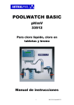
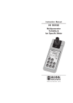
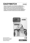
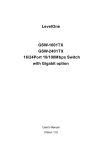
POOLWATCH BASIC pH/Cl inor 16647 o 16648 Para cloro líquido, lecturas de pH/ppm Cl no estabilizado. Célula cerrada amperiométrica de Cl PW Basic Cl inor MANUAL DE INSTRUCCIONES 1 Ref:PW Basic-16647-16648-cast-v2-W11 ÍNDICE páginas 1. Material incluido en el equipo PW Basic pH/Cl inorgánico (16647 o 16648)....................................................................3 2. Descripción del Conjunto PW Basic Cl inorgánico ...........................................................................................................4 2.1 Leyenda del conjunto PW Basic pH/Cl inorgánico ......................................................................................4 2.2 Esquema del equipo PW Basic pH/Cl inorgánico........................................................................................4 3. Cámara de Análisis...........................................................................................................................................................5 3.1 Descripción de la cámara de análisis ..........................................................................................................5 3.2 Esquema de la cámara de análisis..............................................................................................................5 4. Instalación del PW Basic Cl inorgánico ............................................................................................................................ 6 5. Esquemas de Instalación ................................................................................................................................................. 6 6. Carátula PW Basic Cl inorgánico......................................................................................................................................7 6.1 Descripción de la carátula ...........................................................................................................................7 6.2 Esquema de la carátula ...............................................................................................................................7 7. Programación y Ajuste del electrodo de pH y la Célula de Cl Inorgánico.......................................................................8 - 10 8. Puesta en marcha del PW Basic Cl inorgánico ...............................................................................................................10 9. Consejos de Interés .........................................................................................................................................................10 - 11 10. Conexionado PW Basic Cl inorgánico y esquema del regletero ....................................................................................11 10.1 Esquema del conexionado .......................................................................................................................11 10.2 Leyenda del esquema ..............................................................................................................................11 11. Mantenimiento del PW Basic Cl inorgánico ...................................................................................................................12 - 13 12. Dibujos de la célula de cloro inorgánico ........................................................................................................................13 3.1 Partes de la célula de cloro ........................................................................................................................13 3.2 Cambio del electrolito y membrana .............................................................................................................13 13. Garantía ..........................................................................................................................................................................14 14. Problemas y soluciones del PW Basic Cl inorgánico .....................................................................................................14 15. Especificaciones Técnicas del PW Basic Cl inorgánico .................................................................................................15 16. Diagrama de flujo del funcionamiento del PW Basic Cl inorgánico ................................................................................16 - 18 17. Recambios del PW Basic Cl inorgánico (16647 o 16648) ..............................................................................................19 2 Ref:PW Basic-16647-16648-cast-v2-W11 1. MATERIAL INCLUIDO EN EL EQUIPO POOLWATCH BASIC pH / Cloro Inorgánico El PW Basic (16647 o 16648) consta de: .- Central medidora y reguladora de pH, Cloro Residual Libre (15612A2003). .- Electrodo de pH (32460-0005) .- Célula de Cloro Inorgánico (03333R0100) .- Conjunto cable conector para el electrodo de pH (32460-0004) .- Sonda de temperatura PT-100, sólo para la versión 16648 (05468R0001) .- Cámara de análisis (03332R0004) .- Válvula para muestras de agua (11656) .- Cartucho filtrante 5” de 70 micras PP (07955-2005) .- Portacartuchos 5” de tres roscas (07955-2001) .- Detector de caudal, inductivo (03332-1002) .- Solución tampón pH 7 (07955R0010) .- Solución tampón pH 4 (07955R0011) .- Kit montaje (Tornillo, tacos y separadores). .- Juego de instrucciones. 3 Ref:PW Basic-16647-16648-cast-v2-W11 2. 1 LEYENDA DEL CONJUNTO PW BASIC pH / Cloro Inorgánico 1.- Válvula de bola D 20 mm PVC, de entrada de agua. 2.- Central medidora y reguladora de pH, Cloro Inorgánico. 3.- Tapa protectora de la regleta de conexión. 4.- Cartucho filtrante 5” de 70 micras PP 5.- Portacartuchos 5" 6.- Detector caudal. 7.- Cable conector para el electrodo de pH. 8.- Cable conector célula de Cloro Inorgánico, solidario con la célula. 9.- Equipotencial. 10.- Cámara de Análisis. 11.- Flotador metálico 12.- Válvula para regular el caudal. 13.- Vaso para calibrar el electrodo de pH. 14.- Electrodo de pH. 15.- Célula de Cloro Inorgánico. 16.- Válvula para tomar muestras de agua 1/4". 17.- Válvula de bola D 20 mm PVC, de salida de agua. 2. 2 ESQUEMA DEL EQUIPO PW BASIC pH / Cloro Inorgánico PoolWatch Basic Cl inor pH: 7.8 Cl: 1.20 SP: 7,2 SP: 1.25 pH ENTER VAL DOSAGE Cl/Br ESC 14 15 1 2 3 4 4 5 6 7 8 9 10 11 12 13 16 17 Ref:PW Basic-16647-16648-cast-v2-W11 3.1 DESCRIPCIÓN DE LA CÁMARA DE ANÁLISIS A.- Cámara de análisis B.- Zona para ser montada la célula de Cloro Inorgáncio. C.- Zona para ser montado el electrodo de pH . D.- Zona para ser montado el detector de caudal. E.- Conexión del equipotencial. F.- Purga de aire. G.- Válvula para regular el caudal. H.- Área para la calibración del electrodo de pH. H'1.- Recipiente para realizar calibraciones. H'2.- Recipiente para trabajar en continuo. I.- Flotador metálico J.- Tapón acceso al flotador. K.- Entrada de agua. L.- Salida de agua. M.- Tornillos para sujetar la cámara de análisis. 3.2 ESQUEMA DE LA CAMARA DE ANÁLISIS 5 Ref:PW Basic-16647-16648-cast-v2-W11 4. INSTALACIÓN DEL POOLWATCH BASIC CLORO INORGÁNICO El PW Basic Cl inorgánico se entrega montado en un panel de PVC (60 cm x 60 cm) 1.- Fijar el panel a la pared con los separadores suministrados. 2.- Conectar el equipo a una alimentación directa de 230 V.ac, con toma de tierra. (No tienen que depender del funcionamiento de la filtración). 3.- Colocar en la zona de ubicación (C) de la cámara de análisis (A) el electrodo de pH (14).Se desenrosca uno de los tapones que dan acceso a la zona de ubicación (C).Se toma el electrodo de pH y se le sacan las protecciones de plástico de sus dos extremos, luego se rosca éste en la zona de ubicación (C). 4.- Se conexiona el electrodo de pH (14). Se toma el cable de conexión (7) y por su extremo acabado en una terminal rosca se conexiona al electrodo de pH. El cable 7 es el de la izquierda. Corresponden sus conexiones a las posiciones 26 y 27 del regletero. 5.- Colocar en la zona (B) de la cámara de análisis (A) la célula de Cloro Inorgánico (15). Se desenrosca el tapón que da acceso a la zona (B), este tapón consta de dos partes: una rosca de fijación y un tapón propiamente dicho. Cogemos la rosca de fijación, la introducimos por el extremo del cable (8) de la célula de Cloro Inorgánico y procedemos a roscar la célula en su ubicación (C). Las conexiones de la célula de Cloro Inorgánico al regletero son las siguientes: Malla (Azul) 24 (negativo), Activo (Translúcido) 25 (positivo). 7.- Es aconsejable guardar todas las protecciones y tapones para su posible posterior prolongada, por obras de acondicionamiento de la instalación). uso (por ejemplo, durante una parada 8.- La toma de agua que alimentará la entrada de agua al PW Basic tiene que ser lo más representativa posible del agua de la piscina. Para ello se recomienda realizar una instalación, según se indica en el esquema adjunto y filtrar parte del agua por el fondo de la piscina. NOTA: Si la piscina se tiene aún que construir, consultar al Departamento de Asistencia al Cliente de ASTRALPOOL. ATENCION: Es importante que la alimentación del PW Basic tenga una buena toma de tierra, por seguridad y para garantizar el correcto funcionamiento del equipo. En caso de no ser correcta, podría provocar inestabilidad en la lectura de los parámetros. Contemplando este problema aconsejamos dotar al PW Basic de una buena toma de tierra. 5. ESQUEMA DE INSTALACIÓN DESINFECCIÓN CON CLORO LÍQUIDO PISCINA Dosificación de floculante Agua de red Filtro Intercambiador de calor Mín 20 cm Bomba de filtración Tu b o s d e in y e c c ió n de PE 4 x 6 m m Vaso de compensación Cl Depósito de hipoclorito sódio Cubeto de seguridad Tubo de PE 8 x10 mm << Depósito de corrector de pH Tubo de PE 8 x10 mm Cubeto de seguridad << pH NO COLOCAR LOS DEPÓSITOS DE PRODUCTOS QUÍMICOS DEBAJO DE LAS BOMBAS DOSIFICADORAS. LOS PRODUCTOS QUÍMICOS DEBEN DE ESTAR LEJOS DE LAS BOMBAS DOSIFICADORAS Y DEL EQUIPO POOLWATCH BAS IC CLORO INORGÁNICO 6 Ref:PW Basic-16647-16648-cast-v2-W11 6.1 DESCRIPCIÓN DE LA CARÁTULA POOLWATCH BASIC CLORO INORGÁNICO 1. DISPLAY LCD: Display retroiluminado que nos indica el valor de pH y su valor de consigna (“set point”) y también nos indica el valor del Cloro inorgánico en ppm y su valor de consigna (“set point”). La flecha, que está a la derecha del valor de consigna; hacia arriba indica si está utilizando un incrementador y la flecha hacia abajo si está utilizando un minorador. 2. TECLADO DE 4 FLECHAS: Mediante estas flechas nos podemos desplazar en el display cuando entremos en programación. También son teclas de doble función, así la 2a indica el valor de la Tª, la tecla 2b indica la pendiente y asimetría del electrodo, la tecla 2c indica la lectura real del electrodo o sensor (tensión de polarización) y la tecla 2d se utiliza para anular el Delay cuando se active. Pulsando las cuatro teclas a la vez se visualiza la versión del equipo y un código de fabricación. 3. TECLA ENTER: Se utiliza para entrar en programación y para la misma programación. 4 . TECLA VAL: Se utiliza para validar. 5 . TECLA ESC: Se utiliza para salir de programación. 6. PILOTO pH: Indica, cuando se ilumina, que está activado el relé de la bomba de pH. 7. Los PILOTO Cl: Indica, cuando se ilumina, que está activado el relé de la bomba de Cloro símbolos que se utilizan para mostrar el tipo de regulación son los R S ------------Æ indica regulación ON/OFF por salida relé PR S -----------Æ indica regulación proporcional por salida relé PA S --------------Æ indica regulación proporcional por salida analógica (4-20mA) 6.2 DESCRIPCIÓN DE LA CARÁTULA POOLWATCH BASIC 6 7 CONTROL MINOR 1 2d 2a 2c 2b 3 5 4 TECLAS DOBLE FUNCION TEMPERATURA Tecla 2a DELAY PENDIENTE SONDA Tecla 2d Tecla 2 b LECTURA SONDA Tecla 2c 7 Ref:PW Basic-16647-16648-cast-v2-W11 siguientes: 7. PROGRAMACIÓN Y AJUSTE DEL ELECTRODO DE pH Y DE LA CÉLULA DE CLORO Es recomendable que antes de la puesta en marcha del PoolWatch Basic tengamos el agua del vaso de la piscina entre 7-7.6 unidades de pH y entre 1-1.5 ppm de Cloro residual libre (DPD nº1) y una concentración de ácido cianúrico de 0 ppm. 1.- Colocar el mando de puesta en marcha de las bombas dosificadoras en la posición 0 (paro-off). 2.- Mantener cerradas las válvulas de entrada y salida de agua a la cámara de análisis. 3.- Sacar el electrodo de pH de su envase original. 4.- Conectar el electrodo de pH al cable conector de la izquierda (correspondiente a los bornes 26 malla (-), azul ó negro y 27 activo (+) translúcido. 5.- Llenar el vaso de calibración con solución tampón pH 7. Introducir en la parte inferior del electrodo la solución tampón. Seguir el diagrama de flujo (págs. 16-18) de la programación del equipo. Ir a ajuste seleccionando el parámetro de pH. Introducir “SENSOR pH” y pulsar ENTER. Aparecerán unas barras en la pantalla de LCD. Una vez finalizada la calibración aparecerá en la misma pantalla la frase “LECTURA ESTABLE”. Pulsaremos validar (VAL), lo cual confirmará un correcto ajuste del electrodo de pH. 6 .- Enjuagar el electrodo de pH con solución tampón pH 4 antes de realizar el ajuste a pH 4. 7.- Llenar el vaso de calibración con solución tampón pH 4. Repetir la misma operación anterior, pero con solución tampón pH 4. 8.- Seguidamente se saca el electrodo del vaso de calibración, tiramos el contenido de éste y colocamos el electrodo en la zona de ubicación izquierda de la cámara de análisis, desconectando previamente éste del cable de conexión y volviendo a conectarlo ya ubicado en la cámara de análisis. 9.- Sacar la célula de Cloro Inorgánico de su envase original. Colocar en la zona (B) de la cámara de análisis (A) la célula de Cloro Inorgánico (15). Se desenrosca el tapón que da acceso a la zona (B), este tapón consta de dos partes: una rosca de fijación y un tapón propiamente dicho. Cogemos la rosca de fijación, la introducimos por el extremo del cable (8) de la célula de Cloro Inorgánico y procedemos a roscar la célula en su ubicación. 10.- Abrir las válvulas de entrada y salida de agua a la cámara de análisis. 11.- Antes de programar el equipo dejar circular el agua por el interior de la cámara de análisis durante 1/2 h. 12.- Inmediatamente después conectar la Célula de Cloro Inorgánico (ver punto nº 13) y esperar unos 90 minutos con el objeto de conseguir suficiente tensión de polarización. Posteriormente, realizar el ajuste de cloro con DPD - 1 mediante fotómetro, según el diagrama de flujo de la programación (página 16). 13.- Conectar la célula de Cloro Inorgánico en los bornes del regletero siguientes: Malla (Azul) 24 (negativo), Activo (Translúcido) 25 (positivo) Se puede observar en la pantalla del LCD lo siguiente: Parte superior: Lectura de pH y del Set Point programado. La flecha que aparece en el margen derecho indica si está utilizando minorador (p) o incrementador (n) Parte inferior: Lectura de Cloro Inorgánico y el Set Point programado. La flecha que aparece en el margen derecho indica adición de desinfectante (n). La temperatura puede introducirse el valor manualmente de Tª si es un valor estable, de esta forma corregimos la desviación de la lectura por la temperatura. También puede añadirse un sensor de temperatura (versión 16648), la PT-100, de esta forma tendremos un autoajuste automático con la lectura de pH. PROGRAMACIÓN DEL pH 1.- El equipo PoolWatch Basic Cl inorgánico viene comprobado con un valor de ajuste de 7.20 pudiéndose modificar este valor (pág. 15). 2.- Los valores del ajuste de pH están comprendidos entre 0.0 y 14, siendo el ideal de 7.20 3.- El equipo tiene la opción de poder bajar el pH dosificando un minorador o la de subir el pH dosificando un incrementador. Para ello ver el diagrama de flujo (páginas 16-18). El equipo viene de fábrica para dosificar minorador de pH. 4.- Poner en marcha la bomba dosificadora del regulador de pH seleccionando un porcentaje en el caudal de la bomba, adecuado a las características de la piscina, una vez el pH esté ajustado a 7.20 se procede a la programación del Cloro. 8 Ref:PW Basic-16647-16648-cast-v2-W11 ATENCIÓN: A) En caso de utilizar minorador de pH: Si el valor del pH resultante después de la dosificación (ajuste) fuese inferior al valor de SET PONT programado (7.20) es señal de que en la bomba dosificadora del regulador de pH tenemos seleccionado un porcentaje demasiado alto en el caudal de la bomba. Reducir este porcentaje ajustándolo a las características de la piscina. B) En caso de utilizar incrementador de pH (ver flujogramas, páginas 16-18): Si el valor del pH resultante después de la dosificación (ajuste) fuese superior al valor de SET PONT programado (7.20) es señal de que en la bomba dosificadora del regulador de pH tenemos seleccionado un porcentaje demasiado alto en el caudal de la bomba. Reducir este porcentaje ajustándolo a las características de la piscina. O al contrario, si estamos dosificando tanto minorador como incrementador de pH y no hay forma de llegar al valor 7.20 es señal de que el porcentaje seleccionado en el caudal de la bomba es inferior al necesario. Aumentar este porcentaje ajustándolo a las características de la piscina. CALIBRACION DEL ELECTRODO (pH) Cuando introducimos el electrodo de pH en la solución tampón pH 7 y pH 4, puede ocurrir que no se pueda calibrar el electrodo. Introducir el electrodo en la solución limpiadora durante 2 minutos y repetir la calibración. En caso de que persista el problema, proceder a cambiar el electrodo o pulsar, 3 veces, la tecla ESC (escape) en el caso de no disponer del mismo. CALIBRACIÓN DE LA CÉLULA DE CLORO INORGÁNICO Cuando calibramos la célula de Cloro Inorgánico y realizamos el ajuste del Cloro mediante el método del DPD-1, siguiendo el diagrama de puede ocurrir que no se pueda calibrar. Volver a repetir la operación de calibración. En caso de que persista esa situación, cambiar electrolito y membrana de la Célula de Cloro Inorgánico. Si no se dispone de un electrodo de pH o una célula de Cloro Inorgánico nuevo, deberá pulsarse la tecla ESC (escape). Finalmente, cuando se hayan realizado las calibraciones del electrodo de pH y la Célula de Cloro Inorgánico correctamente, quedará el equipo ajustado. ATENCIÓN: La célula de cloro inorgánico no puede utilizarse en presencia de ácido isocianúrico en el agua de la piscina. PROGRAMACIÓN DEL CLORO 1.- El equipo PW Basic Cloro inorgánico viene de fábrica con un valor de Set Point programado de 1.5 ppm. 2.- Tenemos la posibilidad de ajustar el valor de Cl de 0 a 10 ppm (para ello ver los diagrama de flujo, págs. 16-18). 3.- Poner en marcha la bomba dosificadora de cloro, seleccionando un porcentaje en el caudal de la bomba adecuado a las características de la piscina. 4.- Una vez ajustado el nivel de Cl , si el nivel de Cl no es suficiente (hacer análisis del agua de la piscina), entraríamos en programación en equipo, nos iríamos al SET POINT (SET P), seleccionaríamos el parámetro Cl mediante las teclas correspondientes. Seguidamente introduciríamos un valor de SET POINT superior al que tenemos, y pulsaríamos 1 vez, la tecla ENTER y 2 veces la tecla ESC, volviendo al inicio del diagrama de flujo. De esta forma aumentaríamos el nivel de cloro presente en el agua. 5.- De forma análoga, en el caso de que el nivel de Cl sea superior al deseado, entraríamos en programación de la misma forma que se ha escrito anteriormente, hasta llegar al valor de SET POINT, el cual sería modificado por un valor más bajo pulsaríamos 1 vez, la tecla ENTER y 2 veces la tecla ESC, volviendo al inicio del diagrama de flujo. Si el nivel de cloro aun así fuera alto, repetiríamos la operación hasta que se consiga el nivel deseado. 9 Ref:PW Basic-16647-16648-cast-v2-W11 ATENCIÓN: Si el valor del cloro resultante, después de la dosificación, fuese superior al valor programado (ver pantalla LCD) es señal de que: La bomba dosificadora de cloro tiene un porcentaje demasiado alto en el caudal de la bomba. Por lo tanto tendremos que reducir este porcentaje. O al contrario, si estamos dosificando y no hay forma de llegar al valor programado es señal de que: La bomba dosificadora de cloro tiene un porcentaje demasiado bajo en el caudal de la bomba. Por lo tanto tendremos que aumentar este porcentaje. 8. PUESTA EN MARCHA DEL EQUIPO POOLWATCH BASIC pH /Cl Inorgánico Una vez efectuada la instalación y la programación, se procede a la puesta en marcha. 1.- Cerrar la válvula (16) de toma de muestras de agua. 2.- Abrir las válvulas de entrada (1) y salida (17) de agua. 3.- Poner la bomba de filtración en marcha. 4.- Abrir la válvula (12) para regular el caudal en la cámara de análisis dejando circular el agua por su interior y ajustar su caudal a 30 lts/h. (Cuando la cabeza del flotámetro (I) emerge por encima de la señal grabada en la parte frontal de la cámara de análisis el caudal es de 30 lts/h.). 5.- Conectar las bombas dosificadoras y elegir un porcentaje de trabajo adecuado al volumen de la piscina. ATENCIÓN: Es imprescindible en la puesta en marcha del PW Basic encontrarnos con un agua: .- Transparente. .- El valor del pH entre 7 - 7.8 .- El valor del Cl entre 1 y 1.5 ppm MUY IMPORTANTE: El agua de la piscina no debe de haber presencia de ácido cianúrico (= 0 ppm Cys). ELECCIÓN DE LOS VALORES DE TRABAJO EN EL POOLWATCH BASIC pH/Cl Inorgánico Es aconsejable informarnos sobre el margen de trabajo que les permite la legislación aplicable al lugar donde esté instalado el PW Basic respecto a los niveles de cloro y pH. En el caso del pH recomendamos trabajar con valores bajos (próximos a 7.2) para que de este modo tener un mayor porcentaje de cloro libre en forma activa desinfectante. Una recomendación podría ser 7.25 (pH) y 1,25 ppm Cl , aunque serán Vd quienes tomarán esta decisión en base a la filtración, cantidad de bañistas, etc. Para tener mayor precisión en la lectura del Cloro, es recomendable hacer el “ADJUST DPD” en un valor próximo al SP que hemos elegido. Si estos valores son muy distantes entre sí, la lectura del Cloro puede no ser demasiado exacta. Recomendamos que para el seguimiento del equipo utilicen un fotómetro PC-Checkit. 9. CONSEJOS DE INTERÉS - Cuando el sistema de filtración funciona con la ayuda de floculación en continuo, debe tenerse en cuenta inyectar siempre el floculante después de la toma de agua que va a la cámara de análisis. - No colocar nunca ningún producto químico en piscina, en los Skimmers o vaso de compensación. (Ejemplo: floculante en cartuchos, tabletas, etc.).Estos podrían ir directamente al PW Basic y dañar seriamente los electrodos. - Cuando se realice un lavado de filtros, o se utilice el limpiafondos manual, se debe cerrar la válvula de entrada de agua al PW Basic (desde la toma del collarín) para evitar que entre suciedad en el circuito PW Basic. - Por la cámara de análisis siempre tiene que pasar un caudal constante igual a 30 lts/h. - Cuando se realice un tratamiento de recuperación del agua de la piscina no se dejará entrar nunca agua en la cámara de análisis. Para ello es fundamental colocar una válvula en el punto donde se toma el agua del PW Basic y mantenerla cerrada hasta que el tratamiento de recuperación se haya terminado, y los valores en el agua de la piscina sean los normales. 10 Ref:PW Basic-16647-16648-cast-v2-W11 10.1 ESQUEMA DEL REGLETERO DE LOS BORNES DE CONEXIÓN 4 L1 N 230 Vca 5 POWER 6 7 8 10 9 PpH Cl OUT 1 OUT 2 RELAYS 11 12 13 14 15 VCC OUT GND + FLOW - 16 GND PE COMM. 17 18 + - 19 + 20 21 22 - Cl 1 pH OUT 2 OUT 1 OUTPUTS 4-20 mA 23 24 25 26 27 28 PE + PT-100 - 10.2 LEYENDA DEL ESQUEMA DEL REGLETERO DE LOS BORNES 1, 2, 3 Alimentación 230 V ac 50 Hz + toma de tierra. 1 4 Puente para la alimentación al circuito de potencia (ya viene de fábrica) 2 5 Puente para la alimentación al circuito de potencia (ya viene de fábrica) 6 7 Salida 230 V ac para la bomba dosificadora de cloro. Relé 2 8 9 Salida 230 V ac para la bomba dosificadora de pH. Relé 1 10 (-), 11(E) y 12(+) Conexión del detector de caudal. Captador inductivo. 13 (GND),14 (TX),15 (GND),16 (RX) Conexión a comunicaciones, salida RS-485 17,18 Salida 4-20mA, correspondiiente al Cl 19, 20 Salida 4-20 mA, correspondiente al pH 21 22 Salida conexión PT-100, sensor de Tª (la versión 16648 debe de conectarse la PT-100 en estos puntos) 23 Equipotencial 24 25 Conexión de la Célula de Cloro (24 malla azul negativo, 25 activo translúcido positivo). 26 27 Conexión del electrodo de pH (26 - malla color azul ó negro ; 27 + activo color translúcido ) 28 Equipotencial. Nota importante: La calibración de los electrodos de pH y de Cl deben de efectuarse con la conexión del equipotencial. 11 + pH Cl IN 2 IN 1 INPUTS Ref:PW Basic-16647-16648-cast-v2-W11 - EQP 11. MANTENIMIENTO DEL POOLWATCH BASIC CLORO INORGÁNICO PUESTA EN SERVICIO - Observar si hay aire en el interior de la cámara de análisis, en caso de que exista, eliminarlo a través de la purga (F). - Limpiar el filtro de cartucho cuando tenga suciedad. Su función es evitar que ésta entre en la cámara de análisis. Para ello es preciso que esté limpio. - Antes de utilizar los electrodos, comprobar que estén libres de incrustaciones, suciedades o cristalizaciones. En el caso de que el electrodo de pH presentara alguna de estas anomalías, introducirlo en solución limpiadora durante 2 minutos. - Ajustar el electrodo de pH, y Célula de Cloro cuando observemos una desviación entre la lectura del PW Basic pH/Cl inorgánico, respecto a nuestro analizador. - El electrodo de pH, membrana y electrolito de la célula de Cloro tienen una vida estimada de 6 meses. Esta duración dependerá de las características del agua y del uso que se dé al electrodo. No obstante, al tratarse de un elemento de desgaste, no está incluido en la garantía. LIMPIEZA Y ENTRETENIMIENTO DE LOS ELECTRODOS Sométanse el electrodo de medición a inspecciones oculares (aprox. 1 vez al mes) y efectúese su limpieza en caso necesario. Para realizar la limpieza del electrodo, sumergirlo en la solución limpiadora, únicamente el extremo del electrodo (membrana de vidrio) durante 2 minutos. Sería imprescindible que después de cada limpieza los electrodos se introdujeran en solución conservadora de KCl 3 M durante 5 minutos. Limpieza y entretenimiento del filtro 1 vez por semana con agua a presión. ALMACENAMIENTO Verificar que durante su almacenamiento el electrodo de pH tengan en el extremo final del mismo (zona humedecida) el líquido de solución conservadora KCl 3 M que viene de fábrica. En el caso de su evaporación o pérdida accidental, verter un poco de solución KCl trimolar en la caperuza o carcasa protectora. Es imprescindible que la caperuza o carcasa protectora siempre esté humedecida con dicha solución. Las condiciones de almacenaje deben de ser en lugar seco entre temperaturas entre 10ºC hasta 30ºC. Temperaturas de – 15ºC pueden fracturar los electrodos o desnaturalizar el electrolito. : Los electrodos de pH no pueden almacenarse por tiempo indefinido. Por consiguiente no se recomienda almacenarlos durante más de tres meses. : No poner los electrodos de pH al remojo con agua destilada, ya que esto sería causa de un envejecimiento prematuro e irreversible. : No manipular el extremo de los electrodos, donde se conectan el cable, con las manos mojadas porque podría producir un cortocircuito y deteriorar rápidamente el electrodo de referencia y por lo tanto, la vida de los electrodos. VIDA ÚTIL El electrodo de pH está sometido a un envejecimiento natural, aun cuando se manejen reglamentariamente de acuerdo con el empleo que se les dé. La vida útil previsible oscilará entre medio año y un máximo de dos años. (Los electrodos de pH no disponen de garantía) PARADA DE LA INSTALACIÓN - En caso de no funcionar la piscina (final de temporada, obras, etc.), se desconectará el PW Basic y se sacarán el electrodo de pH y la célula de cloro del interior de la cámara de análisis. El electrodo de pH y la célula de cloro se limpian con agua, colocando en sus extremos las protecciones de plástico, humedecidas previamente, y por último serán guardados en su caja. Los orificios donde estaban ubicados el electrodo de pH y la célula de cloro, se cierran por medio de dos tapones plásticos para evitar la entrada de suciedad. Proteger al equipo PW Basic de la suciedad y de la humedad. 12 Ref:PW Basic-16647-16648-cast-v2-W11 - Si es necesario, cada seis meses de funcionamiento, cambiar la membrana y el electrolito de la célula de cloro. Para ello, desconectar la célula de cloro (16) del PW Basic y sacarla fuera de la cámara de análisis. A continuación, desenroscar el protector quedando al descubierto el electrodo, vaciar el electrolito del interior del protector, desenroscar el cierre del protector quedando libre la membrana. Proceder a la sustitución de la membrana por una nueva, roscar el cierre al protector y llenar totalmente éste con electrolito, procurando que no quede ninguna burbuja de aire. Por último, limpiar el electrodo con el electrolito y roscar el electrodo al protector. Colocar la célula de cloro dentro de la cámara de análisis y conexionar la célula al PW Basic. Siempre que se realice esta operación se tendrá luego que proceder al ajuste de la célula de cloro. 12. DIBUJOS DE UNA CÉLULA DE CLORO INORGÁNICO 12.a Partes de la célula de cloro Cable, perfecctamente estanco Cámara de medición, o cierre del conjunto Membrana con un robusto aislamiento construido en “sandwich” Gran superficie de ánodo de cloruro de plata Cátodo de oro Protector, para fijar a la membrana 12.b Cambio de electrolito y de membrana 13 Ref:PW Basic-16647-16648-cast-v2-W11 13. GARANTÍA Toda la gama de conjuntos PW Basic está garantizada contra defectos de materiales y de fabricación en dos años. Esta garantía no incluye la incorrecta manipulación por parte del cliente. En ningún caso esta garantía incluye la sustitución de elementos sometidos a desgaste por su normal utilización, como son los electrodos o el electrolito y membrana de la célula de cloro. 14. PROBLEMAS Y SOLUCIONES POOLWATCH BASIC pH /Cl INORGÁNICO CAUSAS SOLUCIONES Nivel de pH por encima del valor programado (si se usa incrementador) Seleccionó un % de la bomba dosificadora más alto del adecuado. Reducir el % ajustándolo a las características de la piscina. Nivel de pH por debajo del valor programado (si se usa minorador) Seleccionó un % de la bomba dosificadora más alto del adecuado. Reducir el % ajustándolo a las características de la piscina. Nivel de Cloro por encima del valor programado. La bomba dosificadora de cloro tiene un porcentaje más alto del adecuado. Reducir porcentaje adecuándolo a las características de la piscina. Nivel de Cloro por debajo del valor programado. La bomba dosificadora de cloro tiene un porcentaje más bajo del adecuado. Aumentar el porcentaje adecuándolo a las características de la piscina.. a) No se ha efectuado el puente de conexión de los bornes 1-4 y 2-5 del regletero de conexión. b) Filtración parada. c) Activado el delay. a) Efectuar la conexión de los bornes 1-4 y 2-5 del regletero de conexión. b) Si la filtración está en automático esperar a que se ponga en marcha según la hora prefijada, o bien poner la filtración en marcha en forma manual. c) Desactivar el delay pulsando la tecla 2 d. a) Cartucho del filtro sucio a) Limpiar. b) Electrodo de pH o célula de Cl sucios b) Limpiarlos con solución limpiadora. c) Electrodo de pH agotado. c) Cambiarlo. d) Membrana o electrolito de la célula de Cl agotados d) Cambiarlos e) Mala lectura del fotómetro e) Calibrar el fotómetro f) Temperatura del agua elevada > 28ºC f) Introducir el valor de compensación de la temperatura del agua en el equipo mediante la programación (sólo versión 16647). a) No circula agua por la cámara de análisis. a) Comprobar la circulación del circuito hidráulico del PW Basic ANOMALÍAS Led indicador de la conexión a la bomba dosificadora de pH ó Cl, (activado), sin que esté dosificando la bomba dosificadora correspondiente. El análisis físico-químico del agua de la piscina, concretamente el pH y nivel de Cl, no se corresponden con la lectura del PW Basic (Existe mucha diferencia). Está activada la alarma de caudal, aparece intermitentemente “ERROR N.02 FALTA DE CAUDAL”. b) Conexión defectuosa del detector de caudal b) Verificar y realizar la conexión correcta del detector de caudal. No circula agua por el circuito hidráulico del equipo. a) Ensuciamiento del filtro malla. a) Limpiar el filtro malla. b) Presencia de partículas en la cámara de análisis. b) Limpiar la cámara de análisis, debiendo desmontar el tapón de acceso al flotador (J). c) Cerradas las válvulas de entrada o salida. c) Abrir las válvulas de entrad y salida del circuito hidráulico. 14 Ref:PW Basic-16647-16648-cast-v2-W11 15. CARACTERÍSTICAS TÉCNICAS DE LOS EQUIPOS POOLWATCH BASIC pH/Cl INORGÁNICO - Rango de medida pH: 0 a 14 (resolución: 0.1 unidad) - Rango Set Point pH: 0 a 14 - Rango de medida Cl: 0 a 10 ppm (resolución: 0,01 unidad) - Rango Set Point Cl : 0 a 10 ppm - Delay: 10 segundos. - Calibración a pH 7 y pH 4. - Consumo eléctrico del equipo: 25 W - Tensión de alimentación: 230 V Monofásico + Tierra, 50 Hz - Histéresis de conmutación por tiempo: +/- 10 segundos FICHA TÉCNICA POOLWATCH BASIC pH/CLORO INORGÁNICO - Controlador y/o regulador de pH y/o Cloro inorgánico. - Visualización por Display LCD retroiluminado alfanumérico (16 caracteres) - Convertidor ADC de 24 bits con referencia compensada de Tª + filtrado digital de lectura para alta inmunidad a interferencias. - Microprocesador de 16 bits. - 2 Salidas ON / OFF (Relés) de regulación (contactos libres de tensión). - Salida de Tª de serie. - Salidas analógicas de serie 4-20 mA. - Salida comunicaciones RS-485 de serie. - Programación multiidioma (castellano e inglés). - Aviso de electrodo defectuoso en calibración. - Lecturas de pendiente, y asimetrías de los electrodos. - Lectura de corriente directa de la sonda de cloro. Es aconsejable una vez al año realizar la revisión del PW Basic por un técnico especializado. 15 Ref:PW Basic-16647-16648-cast-v2-W11 16 . DIAGRAMAS DE FLUJO DEL POOLWATCH BASIC CLORO INORGÁNICO 16.a.- FLUJOGRAMA PRINCIPAL PpH: 7.5 SR: 7.2 P Cl: 1.25 S R:1.50 ESC ESC ENTER Sel. de entrada P[ pH ] Cl TMP Sel. de entrada P pH [ Cl ] TMP ESC ENTER ESC ENTER Sel. Opcion [ ] CAL Sel. Opcion [ ] CAL Sel. Opcion [CAL] ENTER ENTER Set Point 07.2 ENTER IN SENS pH 07.0 PULSAR ENTER ANALIZAR Cl AGUA PULSAR ENTER ENTER ENTER LECTURA ESTABLE PULSAR VAL VAL IN SENS pH 04.0 PULSAR ENTER ENTER IN SENS pH 4.1 VAL ENTER ENTER ENTER IN SENS pH 7.1 CALIBRACION REALIZADA Sel. Opcion [CAL] Set Point 1.00 INTRODUCIR DPD 1.00ppm IN SENS Cl 1.02 LECTURA ESTABLE PULSAR VAL VAL CALIBRACION REALIZADA LECTURA ESTABLE PULSAR VAL 16 Ref:PW Basic-16647-16648-cast-v2-W11 16.b.- FLUJOGRAMA ELECCIÓN DE IDIOMAS PpH: 7.5 P Cl: 1.2 SP:7.2 SP:1.5 VAL Intr. Password P >: 0000 Cmediante las teclas introducimos el número Intr. Password P >: 1986 Enter Forzar reles Test teclado Forzar reles Test teclado Cx 11 veces Password usuar. Idioma Password usuar. Idioma Enter Idioma CASTELLANO Cintermitente Cx 5 veces Idioma INGLES Cintermitente ENTER Idioma ESC 17 Ref:PW Basic-16647-16648-cast-v2-W11 1 6.c.- FLUJ OG RAM A DE LAS MULTIO PCIO NE S/ M ENÚ DEL INSTALADOR Forzar relé 1 Forzar relé 2 Entrada 1 Entrada 2 Entrada 3 Entrada 4 Ejecución de rutina de forzado de salida relé. Ejecución de rutina de testeo de teclado. Calibrar Calibración de la entrada. Entrada asoc. pH (TMP, IN3, Cl). Tipo regulación ON/OFF (Proporcional). Forzar relés Tipo reactivo MINORADOR (Incrementador). Test teclado Set Point 07.2 Banda propor 01.0 Relé 1 Relé 2 Salida 1 Salida 2 Cnf. entradas Cnf. sal. relé Cnf. sal. 4-20m Comunicaciones Entrada asoc. pH (TMP, IN3, Cl). SI (No) .SI (No) Tipo salida MONITOR (Regulación) Tipo reactivo MINORADOR (Incrementador). SI (No) . NO (Si) . SOLO DPD (DPD + CERO) . 0000 (No tocar) CASTELLANO .(CHECO, PORTUGUÉS, ITALIANO, FRANCÉS, INGLÉS) Set Point 07.2 Banda propor 01.0 N. de terminal 01 (02, 03, …,99) Velocidad com. 9600 (4800, 2400, 38400, 19200) Número serie Ex: 3V00000023 Fecha fabric. Fecha salida Ex: 01/01/ 07 . Ex: 01/02/ 07 Fecha repar. Ex: 01/05/ 07 Trazabilidad Detector caudal Backlight Sonido tecla Sonido alarma Calibración Cl Password usuar. Idioma . 18 Ref:PW Basic-16647-16648-cast-v2-W11 17 . RECAMBIOS DEL EQUIPO POOLWATCH BASIC CLORO INORGÁNICO (16647 o 16648) Nº 1 2 3 4 5 6 7 8 9 10 11 12 13 14 15 16 17 18 CÓDIGO 03334-0201/03334-0201T 07955-2005 07955-2001 03334-0202 03332R1002 03332R0004 03334-0203 15612A2003 03332R0002 32460-0005 03333R0100 07955R0010 07955R0011 03333R0103 03333R0102 05468R0001 16644R0002 16646R0001 DESCRIPCIÓN Circuito agua 1er tramo (16647) /CA 1er tramo opción temperatura (16648) Cartucho 5" malla PP 70 micras Portacartuchos 5" 3 roscas 1/2" Circuito agua segundo tramo Conjunto detector inductivo plástico Cámara de análisis Circuito agua tercer tramo Central PWB-V pH/Cl inorgánico Cable conexión del electrodo Electrodo de pH Conjunto célula cloro inorgánico Solución patrón pH7 Solución patrón pH4 Electrolito célula de cloro inorgánico Membrana célula de cloro inorgánico Sonda de temeratura PT-100 Tarjeta PW-V pH Tarjeta PW-V Cl inorgánico PoolWatchBasicClinor pH: 7.8 SP: 7, 2 C l: 1.20 SP: 1. 25 12 07955R0010 Solución patrón pH7 ENTER pH VAL 13 07955R0011 Solución patrón pH4 8 Cl/Br ESC 03333R0100 Célula de cloro inorgánico 9 11 32460-0005 Electrodo pH 10 10 14 11 03333R0103 Electrolito cloro inorgánico 16 05468R0001 Sonda de temperatura PT-100 16644R0002 Tarjeta PWB pH 1 2 3 4 19 5 6 17 15 03333R0102 Membrana cloro inorgánico 03332R1002 Detector inductivo 16646R0001 Tarjeta PWB Cl inorgánico 7 Ref:PW Basic-16647-16648-cast-v2-W11 5 18 POOLWATCH BASIC pH/Cl inor 16647 or 16648 Control & Regulation Equipment Readings pH and ppm Inorganic Chlorine Chlorine measuring amperometric cell PW Basic Cl inor INSTALLATION AND MAINTENANCE MANUAL 1 Ref: PW Basic-16647-16648-v2-gb-T01 INDEX pages 1. Parts include in the equipment PW Basic pH/ Inorganic Chlorine (16647 or 16648) .......................................................3 2. Descripction equipment PW Basic Inorganic Chlorine .....................................................................................................4 2.1 Legend equipment PW Basic pH/ Inorganic Chlorine.................................................................................4 2.2 Schema equipment PW Basic pH/ Inorganic Chlorine ................................................................................4 3. Analisys chamber..............................................................................................................................................................5 3.1 Description of the analisys chamber............................................................................................................5 3.2 Schema of the analisys chamber.................................................................................................................5 4. Instalment of a equipment PW Basic pH/Inorganic Chlorine ............................................................................................ 6 5. Instalment schema............................................................................................................................................................ 6 6. Case PW Basic pH/Inorganic Chlorine .............................................................................................................................7 6.1 Description of the case ................................................................................................................................7 6.2 Schema of the case .....................................................................................................................................7 7. Programming and adjusting of the pH probe and the Inorganic Chlorine Cell.................................................................8 - 10 8. Starting of PW Basic pH/ Inorganic Chlorine ...................................................................................................................10 9. Recommendations of importance ....................................................................................................................................10-11 10. PW Basic Cl inorganic working and grid graph...............................................................................................................11 10.1 Diagram grid conectors graph ...................................................................................................................11 10.2 Legend of the diagram...............................................................................................................................11 11. Maintenance equipment PW Basic pH/ Inorganic Chlorine ...........................................................................................12 - 13 12. Draws Inorganic Chlorine cell (chlorine sensor) .............................................................................................................13 12.1 Parts of the sensor chlorine .......................................................................................................................13 12.2 Changes electrolyte and membrane..........................................................................................................13 13. Guarantee .......................................................................................................................................................................14 14. Problems and solutions of the equipment PW Basic pH/ Inorganic Chlorine .................................................................14 15. Technical characteristics PW Basic pH/ Inorganic Chlorine ...........................................................................................15 16. Flow chart PW Basic pH/ Inorganic Chlorine .................................................................................................................16 - 18 17. Spare parts PW Basic pH/ Inorganic Chlorine (16647 or 16648) ..................................................................................19 2 Ref: PW Basic-16647-16648-v2-gb-T01 1. PARTS INCLUED POOLWATCH BASIC pH / Inorganic Chlorine The equipment PW Basic pH/Cl inorganic 16647 or 16648 is formed by: .- pH measurement and controller exchange, Free Residual Chlorine (15612A2003) .- pH probe (32460-0005) .- Inorganic Chlorine Cell (03333R0100) .- Set of connector wire (cable) for pH probe (32460-0004) .- Analysis chamber (03332R0004) .- Valve for water sample (11656) .- Pleated cartridge 5" of 75 microns (07955-2005) .- Threads cartridge holder 5" (07955-2001) .- Flow sensor, inductive (03332-1002) .- Buffer solution pH 7 (07995R0010) .- Buffer solution pH 4 (07955r0011) .- Assembly kit (screws, rawls and separators). .- Instructions set. 3 Ref: PW Basic-16647-16648-v2-gb-T01 2.1 DESCRIPTION EQUIPMENT POOLWATCH BASIC pH / Inorganic Chlorine 1.- Ball check valve D 20 mm PVC, of water admission. 2.- pH measurement and controller exchange, Inorganic chlorine. 3.- Protective lid of tag strip. 4.- 1/2" filter air escape. 5.- Wound cartridge 75 microns 6.- Cartridge holder 5" 7.- Flow detector. 8.- Cable connector for pH probe. 9.- Cable connector Inorganic chlorine cell. 10.- Equipotential. 11.- Analysis Chamber. 12.- Metallic float 13.- Valve to regulate the flow. 14.- Jug to calibrate the pH probe. 15.- pH probe. 16.- Inorganic chlorine cell. 17.- Valve to take water samples 1/4". 18.- Ball check valve D 20 mm PVC, of water output. 2.2 SCHEMA EQUIPMENT POOLWATCH BASIC pH / Inorganic Chlorine PoolWatch BasicClinor pH: 7.8 SP: 7,2 Cl: 1.20 SP: 1.25 pH ENTER VAL Cl/Br ESC 14 15 1 2 3 4 5 4 6 7 8 9 10 11 12 13 16 17 Ref: PW Basic-16647-16648-v2-gb-T01 3.1 ANALYSIS CHAMBER DESCRIPTION A.- Analysis Chamber B.- Zone to assemble the Inorganic Chlorine Cell. C.- Zone to assemble the pH electrode. D.- Zone to assemble the flow detector. E.- Equipotential connection. F.- Air escape. G.- Valve to regulate the flow. H.- Area to calibrate the pH electrode. H'1.- Vessel to make the calibration. H'2.- Vessel for non stops work. I.- Metallic float J.- Lid of float access. K.- Water admission. L.- Water outlet. M.- Screws to hold the analysis chamber. 3.2 DESCRIPTION OF THE ANALYSIS CHAMBER 5 Ref: PW Basic-16647-16648-v2-gb-T01 4. INSTALMENT PPOLWATCH BASIC pH/INORGANIC CHLORINE The PW Basic is presented in a PVC panel (60 cm x 60 cm) 1.- Fix the panel to the wall with the separators provided. 2.- Connect the set to a 230 v. ac with a direct earth connection (they do not have to depend on a filter working). 3.- Put the pH electrode (14) in the location area (C) of the analysis chamber (A) .One of the lids of access to the location area must be unscrewed (C). Take the pH electrode and remove the plastic protections in both extremes, then screw it in the location zone (C) 4.- Connection of pH electrode (14). Take the wire connection (7) and connect it to the pH electrode through the extreme ended in a thread. The 7 wire is the one on the left. Its connections correspond to the positions 26 and 27 in the grid. 5.- Put the cell of Inorganic Chlorine (15) in the zone (B) of the analysis chamber (A). Unscrew the lid of access to zone (B). This lid has two parts: a fixing thread and a lid. We take the fixing thread, we put it though the wire extreme (9) of the Inorganic Chlorine cell and we proceed to wind the cell in its location (B). The connections of the Inorganic Chlorine cell to the grid are the following; Heald (Blue) 24 (negative), Active (Translucent) 25 (positive) 6.- It is advisable to sep all the protections and lids for a possible future use (for instance, during a long stop, due to reparisons, etc). 7.- The water connection that feeds the water admision to the PW Basic must be as similar as possible to the swimming pool water. This is why we recommend making an instalment according to what is shown in the graph enclosed. We also recommend filtering part of the water through the bottom of the pool. NOTE: In case the swimmimg pool has not been built ywt, ask the department of customer Assistance in ASTRAL POOL. ATTENTION: It is important that the feeding in PW Basic has a good earth connection, as a security and also to guarantee its proper functioning. Otherwise, it could provoke instability in the parameters reading. Taking this into account, we advise to give the PW Basic a proper earth connection. 4. INSTALMENT SCHEME DISINFECTION WITH LIQUID CHLORINE POOLWATCH BASIC pH/INORGANIC CHLORINE SWIMMINGPOOL Filter Exchange temperature M ín 30 c m Non stop flocculation unit Net water Mín 20 cm Pump recirculation I n je c t io n P E p ip e s 4 x 6 mm << Safety basin PE Pipe 8 x10 mm Tank sodium hypoclorite Tank pH corrector PE Pipe 8 x10 mm Safety basin << Compensation tank NOT TO PLACE THE TANKS OF CHEMICAL PRODUCT UNDER THE DOSING PUMPS. THE CHEMICAL PRODUCTS MUST BE FAR FROM THE DOSING PUMPS AND OF THE EQUIPMENT POOLWATCH BASIC. 6 Ref: PW Basic-16647-16648-v2-gb-T01 6.1 DESCRIPTION OF THE CASE POOLWATCH BASIC pH / INORGANIC CHLORINE 1. DISPLAY LCD: Back lightened display that shows the pH value and its set point value. It also shows the Inorganic Chlorine value and its set point value. The arrow to the right of the set point value shows if an pH enhancer is being used when it is upwards and it is downwards, shows that a pH reducer 2. 4 ARROW KEYBOARD: We can move in the display through these arrows when we enter the programme. They are double function keyboard, hence the second shows the value of the third, the 2a button shows the value of temperature, 2b button shows the probe slope and asymmetry, the 2c button shows the electrode reading (polarization voltage) and the 2d button is used to cancel the Delay when it is switched on. Pressing the four buttons at a time, you can see the equipment version and a manufacturing code. 3. ENTER BUTTON: It is used to enter the programme and for the programme itself. 4. VAL BUTTON: It is used to validate. 5. ESC BUTTON: It is used to go out of the programme. 6. pH PILOT: When it is enlighted, it shows that the pump relay is switched on. 7. Cl PILOT: When it is enlightened, it shows that the Chlorine pump relay is switched on. The symbols that are in use for showing the type of regulation are the following ones: R S ------------Æ Indicates regulation ON/OFF for exit relay PR S -----------Æ Proportional regulation indicates for exit relay PA S --------------Æ It indicates proportional regulation for analogical exit (4-20mA) 6.2 SCHEMA OF THE CASE POOLWATCH BASIC pH / INORGANIC CHLORINE POOLWATCH BASIC 6 7 CONTROL MINOR 1 2d 2a 2c 2b 3 5 4 KEYS DOUBLE FUNCTION TEMPERATURE Key 2a DELAY SENSOR SLOP Key 2d Key 2 b SENSOR READING Key 2c 7 Ref: PW Basic-16647-16648-v2-gb-T01 7. PROGRAMMING AND ADJUSTMENT OF THE pH PROBE AND THE INORGANIC CHLORINE CELL Before switching on the PoolWatch Basic pH/Inorganic Chlorine it is recommended to have the water in the pool box between 7-7.6 pH units and between 1-1.5 ppm of the free residual Chlorine (DPD nº1). 1.- Put the starter command of the dispenser pump in 0 position (off). 2.- Keep closed the inlet and outlet valve water to the analysis chamber. 3.- Take the pH electrode out of its original container. 4.- Connect the pH electrode to the wire connector on the left (corresponding to the connector 26 blue heald (-) and 27 active (+) translucent. 5.- Fill the jug to calibrate with buffer solution pH 7. Put the buffer solution in the inferior part of the electrode. Follow the signal flow graph planning of the equipment (pages 16-18). Go to adjustment and select the pH parameter. Introduce "SENSOR pH" and press "ENTER". Some bars will appear on the LCD screen. Once the calibration is finished, the sentence "STABLE READING" will appear on screen. We will press validate (VAL), which will confirm a correct adjustment of the pH electrode. 6 .- Rinse the pH electrode with buffer solution pH 4 before doing the adjustment pH 4. 7.- Fill the jug to calibrate with buffer solution pH 4. Do the same as before but using buffer solution pH 7. 8.- Take out the electrode from the jug to calibrate; throw all the content out and put the electrode in the location zone which is to the left of the analysis chamber, switching it off from the wire connection and switching it on once it is located in the analysis chamber. 9.- Remove the Inorganic Chlorine cell from its original container. Put the Inorganic Chlorine cell (15) in the zone (B) of the analysis chamber (A). Unscrew the lid of access to zone (B). Two parts form this lid: a fixing thread and a lid. Take the fixing thread, put it through the wire extreme (9) of the Inorganic Chlorine cell and proceed to wind the cell in its location. 10.- Open the output and input water valves to the analysis chamber. 11.- Leave the water run through the interior of the analysis chamber during 1/2hour. 12.- Immediately after, connect the Inorganic Chlorine cell and wait 90 minutes to achieve enough bias voltage. Afterwards, make the Chlorine adjustment with DPD-1 photometer, according to signal flow graph (page 16). 13.-Connect the Inorganic Chlorine cell in the grid following connectors. Heald (Blue) 24 (negative), Active (Translucent) 25 (positive) You will see the following on the LCD screen: Superior part: Reading of the pH and planned set point. The arrow appearing on the right margin shows whether a reducer (p) or a increaser (n) is being used. Inferior part: Reading of Inorganic Chlorine and the programmed set point. The arrow appearing on the right margin shows the disinfectant addition. (n). If it is a stable value, the parameter can be introduced by hand; hence we will correct the deviation from the temperature reading. A temperature sensor can also be added (version 16648), the PT-100 with its corresponding electronic sheet. Then we will have an automatic self-adjustment with the pH reading. pH PROGRAMMING 1.- The PoolWatch Basic pH/Inorganic Chlorine equipment is tested with an adjusting value can be modified (see pages 16). 2.- The pH value adjustments are between 0.0 and 14, being the ideal value 7.20. 3.- The equipment has the option of lowering the pH, using a reducer or increasing the pH, using a enhancer. To do this, look at the signal flow graph. The equipment is already manufactured to ration the pH reducer. 4.- Switch on the pH adjuster dispenser pump. Do this choosing a percentage in the pump flow volume; this must be suitable to the pool characteristics. Once the pH is adjusted to 7.20, we will proceed to the Chlorine programming. 8 Ref: PW Basic-16647-16648-v2-gb-T01 ATTENTION: A) In case of using a pH reducer: If the value of the resulting pH after the rationing (adjustment) was inferior to the value of the planned SET POINT (7.20), it is a sign that the dispenser pump from the pH adjuster we have selected a percentage which is too high in the pump volume flow. Reduce this percentage adjusting it to the pool characteristics. B) In case of using a pH enhancer (see flow charts, pages 16-18): If the value of the resulting pH after the rationing (adjustment) was superior to the value of the planned SET POINT (7.20), it is a sign that in the dispenser pump from the pH adjuster we have selected a percentage which is too high inn the pump volume flow. Reduce this percentage adjusting it to the pool characteristics. On the contrary, if we are rationing both, the reducer as web as the enhancer, and we can not reach the 7.20, it means that the percentage chosen in the pump volume flow is inferior to the one we need. We have to increase this percentage adjusting it to the pool characteristics. ELECTRODE CALIBRATION (pH) When we insert the pH electrode in the buffer solution pH 7 and pH 4, it may accur that it appears in the LCD screen "faulty electrode”. Put the electrode in the cleaning solution for two minutes and repeat the calibration. In case that "faulty electrode" persists, proceed to change the electrode. If you do not have a new electrode, you have to press the ESC button (escape). CALIBRATION OF INORGANIC CHLORINE CELL When we calibrate the Inorganic Chlorine cell and we make the Chlorine adjustment through the DPD-1 method, if we follow the diagram it could happen that it appears "faulty electrode". Repeat the calibration operation. In case that "faulty electrode" persists, change the electrolyte and the membrane from the Inorganic Chlorine cell. If you do not have a pH electrode or a new Inorganic Chlorine cell, you have to press the button ESC (escape). If you have a new electrode, you should do the operations above mentioned and calibrated it. Finally, when you have done the calibration of the electrode and the Inorganic Chlorine cell properly, the equipment will be adjusted. ATTENTION: The cell of inorganic chlorine cannot be in use with presence in the water of the swimming pool of cianuric acid. CHLORINE PROGRAMMING 1.- The PoolWatch Basic pH/Inorganic Chlorine equipment is manufactured with a programmed Set Point value of 1.5 ppm. 2.- We have the possibility of adjusting the Cl value from 0 to 10 ppm (to do this see flow charts, pages 16-17). 3.- Switch on the Cl dispenser pump, selecting a percentage in the pump flow adequate to the swimming pool characteristics. 4.- If the Cl is not enough once the Cl is adjusted (analyse the pool water), we would enter the equipment programming. Go to SET POINT (SET P), select the mV parameter with the corresponding arrows. Then, introduce a SET POINT value superior to the one we have and press ENTER button; we will go back to the flow graph. Doing this we increase the chlorine level in the water. 5.- In a similar way, in case the Cl is superior to the one we want, we would enter the equipment programming following the above mentioned, until we reach the SET POINT value. This will be modified for a lower value. then press ENTER and go back to the beginning of the flow graph. If after doing this the chlorine level is still high, we have to repeat this step until we achieve the level we want. 9 Ref: PW Basic-16647-16648-v2-gb-T01 ATTENTION: If the chlorine values after the dosing is superior to the programmed value (see LCD screen ) it means: The chlorine dispenser pump has a percentage which is too high in the pump flow. Hence, we will have to reduce this percentage. On the contrary, if we are dosing and we can not reach the programmed value it means that: The chlorine dispenser pump has a percentage which is too low in the pump flow. We will have to increase this percentage. 8. STARTING OF POOLWATCH BASIC pH / INORGANIC CHLORINE Once finished with the installation and programming, starting of PW Basic is carried out. 1.- Close sample taking valve (16) 2.- Open water inlet (1) and outlet (17) valves. 3.- Start filtering pump. 4.- Open valve (12) in order to regulate flow in the analysis chamber, letting water circulate inside and adjust its flow to 30 lts/h (When the flota top (I) emerges over the signal engraved on the front part of the analysis chamber, flow is 30 lts/h). 5.- Switch dispenser pumps on and choose a work proportion that suits swimming pool volume. ATENTION! It is essential that when we start PW Basic we have water in the following conditions: - Clear. - pH value between 7 - 7.8 - Chlorine value between 1-1.5 ppm - VERY IMPORTANTLY: The water of the swimming pool does not owe of credit presence of cyanuric acid (= 0 ppm Cys). ELECTION OF WORKING VALUES IN THE POOLWATCH BASIC pH / INORGANIC CHLORINE It is recommended to have the information about the working margins that the legislation allows respecting Chlorine and pH levels in the place where it is installed. In the case, we recommend to work with low values (close to the 7.2), hence we have a higher percentage of free chlorine in form of active disinfectant. One recommendation is 7.25 (pH) and 1,25 ppm Cl, although you will take the final decision according to the filtering base, quantity of swimmers, etc. To have a higher precision in the chlorine reading, it is recommended to make the "ADJUST DPD" in an approximate SP value to the one we have chosen. If these values are distant one to the other, the Chlorine reading may not be accurate. We recommend that for the set monitoring you use a photometer PC-Checkit. 9. RECOMMENDATIONS OF IMPORTANCE - When the filtering system works with the help of continuous flocculation, you have to take into account to inject the flocculating after the water connection to the analysis chamber. - Do not put any chemical product in the pool, in the skimmers or in the balance tank. (Example: cartridge or tablets flocculant). these could go directly to the PW Basic and damage seriously their electrodes. - When a filter cleaning is done or when you use a manual bottom cleaner, you have to close the input water valve to the PW Basic (in the collar intake) to avoid the dirt go inside the PW Basic circuit. - A constant flow of 30 litres per hour has to go through the analysis chamber. - When a water recuperation treatment of the pool is done, we will not let water go inside the analysis chamber. To do this, it is essential to install a valve in the place where the water of the PW Basic is taken and keep it closed until the recuperation treatment is finished and the water values in the pool are the normal ones again. 10 Ref: PW Basic-16647-16648-v2-gb-T01 10.1 GRID CONNECTORS GRAPH 4 L1 N 5 POWER 230 Vca 6 7 8 9 PpH Cl OUT 1 OUT 2 RELAYS 10 11 12 13 14 15 VCC OUT GND + FLOW - 16 GND PE COMM. 17 18 + - 19 + 20 21 22 - Cl 1 pH OUT 2 OUT 1 OUTPUTS 4-20 mA 23 PE PT-100 24 25 26 27 28 - + - pH Cl IN 2 IN 1 INPUTS + EQP 10.2 LEGEND OF THE DIAGRAM OF GRID CONNECTOR 1, 2, 3 Input 220 V ac 50/60 Hz + earth connection. 1 4 Bridge to feed the power circuit (it is already included in the manufacturing) 2 5 Bridge to feed the power circuit (it is already included in the manufacturing) 6 7 Output 230 V ac for the Chlorine dispenser pump. Relay 2 8 9 Output 230 V ac for the pH dispenser pump. Relay 1 10 (-), 11(E) and 12(+) Connection to the flow detector. Inductive pickup. 13 (GND),14 (TX),15 (GND),16 (RX) Connectors to communicators. 17,18 Output mA Cl (optional) 19, 20 Output mA pHl (optional) 21 22 Output connection PT-100, sensor Tª (Optional) 23 Equipotential 24 25 Connection to the chlorine cell (24 negative blue heald, 25 positive active translucent). 26 27 pH probe connection (26 heald – blue 27 active - translucent). 28 Equipotential. Important note: The calibration of the pH probe and of Cl sensor they have to of be effecting by the connection of the equipotential. 11 Ref: PW Basic-16647-16648-v2-gb-T01 11. MAINTENANCE EQUIPMENT POOLWATCH BASIC pH/INORGANIC CHLORINE - Observe if there is air in the analysis chamber. Should this be the case, take it out through a blowdown (F). - Clean the cartridge filter when it is dirty. Its function is to avoid that this goes into the analysis chamber. This is why it is necessary that it is clean. - Adjust the pH electrode and the Chlorine cell when we notice a deviation in the PW Basic pH/Inorganic Cl reading respecting our analyser. - The pH probe, membrane and Chlorine electrolyte cell has an approximate endurance of 6 months. This duration depends on the water characteristics and the usage you give the electrode. However, due to the fact it is a detrition element, it is not included in the guarantee. SETTING OFF Before using the electrodes, check that they do not have any dirt or crystallisation. In the case the electrodes shows any irregularity, put the cleaning solution for two minutes. CLEANING AND MAINTENANCE OF THE PROBES Revise and examine the electrode once a month approximately) and clean it if necessary. To clean the electrode, introduce it in the cleaning solution, only the electrode extreme (glass membrane) for two minutes. It is necessary to introduce the electrodes in conservative solution of KCl 3 M for 5 minutes. Clean and maintain the filter once a month with a draft water. STORAGE The pH probe must have the extreme (wet zone) in conservative solution KCl 3 M. For this reason, you have to pour a little trimolar solution in the protective cap or casing. It is essential that the cap or casing sponge is humid in that solution. ATTENTION: The pH electrode can not be stored for an unlimited time. Hence, we advise you not to keep them for more than three months. ATTENTION: Do not immerse the electrode in distilled water, this may cause a premature ageing. ATTENTION: Not to manipulate the end of the probes, where they connect the cable, with the wet hands because it might produce a short circuit and spoil rapidly the electrode of reference and therefore, the life of the probes. USEFUL LIFE The pH probe has a natural ageing despite you use it according to the rules, the electrode useful life will be between half a year and two years maximum. The pH probes do not have a guarantee. STOP OF THE INSTALLATION .- In case you do not use the swimming pool all year (end of season, repairing, etc) the PW Basic will be switched off and the pH probe and Chlorine cell will be taken out from the analysis chamber. The pH probe will be immersed in the cleaning solution by its glass side for a minute. Afterwards, it will be cleaned with water, putting the plastic protection in the extreme. You should then keep it in its box. .- May it be necessary, change the membrane and the Chlorine electrode cell every six months of functioning. To do this, disconnect the Chlorine cell (16) from the PW Basic and take it out from the analysis chamber. Afterwards, unscrew the protector, leaving it outside the electrode. Take the electrolyte from inside the protector and then unscrew the protector closure, leaving the membrane free. Substitute the membrane for a new one, wind the closure to the protector and fill it with the electrolyte, trying not to leave any air inside. Finally, clean the electrode with the electrolyte and wind the electrode to the protector. .- Put the Chlorine cell incide the analysis chamber and connect the cell to the PW Basic. Whenever you do this, you will have to adjust the Chlorine cell afterwards. 12 Ref: PW Basic-16647-16648-v2-gb-T01 .- In case the swimming pool is not working (end of season, repairs, etc.) the PW Basic will be switched off and the pH electrode and Chlorine cell will be taken out from the chlorine chamber. The pH probe and the chlorine cell must be cleaned with water, putting in the extremes their plastic protectors and keeping them in their boxes. The holes where the pH electrode and the Chlorine cell were placed, will be closed with two plastic lids to avoid getting dirty. Protect the PW Basic equipment from the dirt and the humidity. 12. DRAWS INORGANIC CHLORINE CELL (CHLORINE SENSOR) 12.a Parts of the chlorine sensor 12.b Changes electrolyte and membrane 13 Ref: PW Basic-16647-16648-v2-gb-T01 13. GUARANTEE All the PW Basic equipment range has a guarantee on material and manufacturing failures for two years. This guarantee does not include the misuse on the customer's side. This guarantee does not include in any case the substitution of the detrition elements such as the electrodes. 14. PROBLEMS AND SOLUTIONS POOLWATCH BASIC pH /Cl INORGANIC PROBLEMS CAUSES SOLUTIONS pH level above the programmed value (if enhancer is used) You selected a % of the dis-penser pump higher than the suitable one. Reduce the % adjusting it to the pool characteristics. pH level below the programmed value (if reducer is used) You selected a % of the dis-penser pump higher than the suitable one. Reduce the % adjusting it to the pool characteristics. Chlorine level over the programmed value. The chlorine dispenser pump has a higher percentage than the suitable one. Reduce the percentage adjusting it to the pool characteristics. Chlorine level below the programmed value. The chlorine dispenser pump has a lower percentage than the suitable one. Increase the percentage adjusting it to the pool characteristics. a) The connection bridge of the connectors 1-4 and 2-5 of the grid connectors has not been done. b) Filtering stopped a) Do the connection to the connectors 1-4 and 2-5 of the grid connector. b) If the filtering is in automatic mode, wait until it starts working according to the selected time, or switch the filtering on manually. Led indicator of the pH or Cl pump dispenser connector (activated) but the pump dispenser is not working. c) Switch off the delay pressing the button 2d. c) Delay activated The engineered valve does not open and the relay is on. Improper connection The physicochemical analysis of the pool water, that is the pH and Cl level do not correspond to the PW Basic reading. (There is too much difference) a) Dirty cartridge filter (see pages 5-6 point n 5) a) Clean. The alarm of wealth is activated, there appears discontinuously" ERROR N.02 LACK FLOW ". b) Dirty probe o chlorine sensor (cell) b) Clean with cleaning solution. c) Expired electrodes. c) Change them. d) Unproper photometer reading. d) Calibrate photometer e) High water temperature > 28ºC e) Insert the compensating value of water temperature in the equipment through the programming (only versdion 16647) a) There is no water running through the analysis chamber a) Check the hydraulic circuit circulation of PW b) Faulty connection to the flow detector b) Verify and do the right connection to the flow detector. a) It does not circulate water for the hydraulic circuit of the equipment. Review power connection. Soiling of the filter mesh. a) The filter Cleans mesh. b) Presence of particles in the analysis chamber. c) b) To clean the analysis chamber, must dismantle the stopper of access to the float (J). Closed the valves of entry or exit c) To open the valves of enter and exit of the hydraulic circuit. 14 Ref: PW Basic-16647-16648-v2-gb-T01 15. TECHNICAL CHARACTERISTICS OF THE POOLWATCH BASIC pH /Cl INORGANIC EQUIPMENT - Measure range pH: 0 to 14 (resolution: 0.1 unit) - pH Set Point range: 0 to 14 - Cl Measure range: 0 to 10 (resolution: 0.01 unit) - Cl Set Point range: 0 to 10 ppm - Delay: 10 seconds - Calibration to pH 7 and pH 4 - Power consumption of equipment: 5W - Feed tension: 230 V monophasic + earth, 50 Hz - Commutation hysteresis for time: +/- 10 seconds TECHNICAL SPECIFICATIONS POOLWATCH BASIC - Controller and/or Inorganic Chlorine regulator. - Visualisation through LCD display backlightened alphanumeric (16 characters) - 24 bits dynamotor ADC with balanced lining up of temperature digital filtering reading to have a high immunity to jamming. - 16 bits microprocessor. - 2 regulation outputs ON/OFF (relay) (free power connectors) - Temperature output - Output 4-20 mA - Communication output. - Multilanguage programme. - Warning of faulty electrode in calibration. - Readings of slope and asymmetries of the probes. - Reading of direct current of the sensor of chlorine. It is advisable to make a review of the equipment PoolWatch Basic once a year by a specialised technician. 15 Ref: PW Basic-16647-16648-v2-gb-T01 16 . FLOW CHART POOLWATCH BASIC pH/INORGANIC CHLORINE 16.a.- GENERAL FLOWCHART PpH: 7.5 SR: 7.2 P Cl: 1.25 S R:1.50 ESC ESC ENTER Sel. Entrance P[ pH ] Cl TMP Sel. Entrance P pH [ Cl ] TMP ESC ENTER ESC ENTER Sel. Option [ ] CAL Sel. Option [ ] CAL Sel. Option [CAL] ENTER ENTER Set Point 07.2 ENTER IN SENS pH 07.0 PRESS ENTER ANALYZE Cl WATER PRESS ENTER IN SENS pH 7.1 VAL STABLE READING PRESS VAL ENTER IN SENS pH 4.1 VAL INTRODUCE DPD 1.00ppm IN SENS Cl 1.02 PRESS ENTER Set Point 1.00 ENTER STABLE READING PRESS VAL IN SENS pH 04.0 ENTER ENTER ENTER ENTER CALIBRATION REALIZED Sel. Option [CAL] VAL CALIBRATION REALIZED STABLE READING PRESS VAL 16 Ref: PW Basic-16647-16648-v2-gb-T01 16.b.- FLOWCHART LANGUAGE SELECTION PpH: 7.5 PCl: 1.2 SP:7.2 SP:1.5 VAL Intr. Password P >: 0000 CBy means of the keys, we introduce the number Intr. Password P >: 1986 Enter Forze relays Keyboard test Forze relays Keyboard test Cx 11 times User password Language User password Language Enter Language ENGLISH Cdiscontinuously Cx 5 times Language SPANISH Cdiscontinuously ENTER Language ESC 17 Ref: PW Basic-16647-16648-v2-gb-T01 16.c.- FLOWCHART MULTIOPTIONS/ INSTALLER MENU · Force relay 1 Execution of routine of relay outlet · Force relay 2 Execution of routine test of keyboard · In 1 · Calibrate Calibration of the inlet · In 2 · In 3 · In 4 · Force relays · Keyboard test · In config. · Relay 1 · Associated in pH (TMP, In3, Cl). · Relay 2 · Regulation type ON/OFF (Proportional). · Reagent type pH minus (pH plus) · Set Point 07.2 · Porport. Band 01.0 · Relay out. Cnf · Out 1 · 4-20mA out. Cnf. · Out 2 · Communications · Traceability · Volume detector YES (NO) · Blacklight YES (NO) · Key sound YES (NO) · Alarm sound NO (YES) · Associated in pH (TMP, In3, Cl). · Type of out MONITOR (Regulation). · Reagent type pH minus (pH plus) · Set Point · Cl calibration Only DPD (DPD +ZERO) · User password 0000 (No to touch) · Language ENGLISH SPANISH CZECH POTUGUES ITALIAN FRENCH 18 07.2 · Porport. Band 01.0 · Terminal num 01 (02, 03, ..., 99) · Comm. speed 9600 (4800, 2400, 38400, 19200) · Serial number Ex: 3V00000023 · Manufac. date Ex: 01/01/07 · Exit date Ex: 01/02/07 · Repair date Ex: 01/05/07 Ref: PW Basic-16647-16648-v2-gb-T01 17 . SPARE PARTS POOLWATCH BASIC pH/INORGANIC CHLORINE (16647 or 16648) Nº 1 2 3 4 5 6 7 8 9 10 11 12 13 14 15 16 17 18 CODE 03334-020103334-0201T 07955-2005 07955-2001 03334-0202 03332R1002 03332R0004 03334-0203 15612A2003 03332R0002 32460-0005 03333R0100 07955R0010 07955R0011 03333R0103 03333R0102 05468R0001 16644R0002 16646R0001 DESCRIPTION Water cir cuit first section (16647)/Water cir cuit first section temperature (16648 Filtering cartridge 5" PP 70 microns Cartridge holder 5" connection 1/2"F Water cir cuit the second section Inductiv e detector Analy sis chamber Water cir cuit the third section Transmitter PWB-V pH/Cl inorganic pH probe cable set pH probe Inorganic chlorine sensor Buf f er solution pH7 Buf f er solution pH4 Inorganic chlorine ele ctrolyte Inorganic chlorine membrane cup PT-100 temperature sens or pH PW-V card Inorganic chlorine PW-V card PoolWatchBasicClinor pH: 7.8 SP: 7, 2 C l: 1.20 SP: 1. 25 12 07955R0010 Buffer solution pH7 ENTER pH VAL 13 07955R0011 Buffer solution pH4 8 Cl/Br ESC 11 03333R0100 Inorganic chlorine sensor 9 32460-0005 pH probe 10 10 14 11 03333R0103 Inorganic chlorine electrolyte 16 05468R0001 PT-100 temperature sensor 16644R0002 pH PW-V card 1 2 3 4 19 5 6 15 03333R0102 Inorganic chlorine membrane 17 03332R1002 Inductive detector flow 16646R0001 Inorganic chlorine PW-V card 7 Ref: PW Basic-16647-16648-v2-gb-T01 18 5