1
POOLWATCH BASIC
pH/mV
33512
Para cloro líquido, cloro en
tabletas y bromo
Manual de instrucciones
1
Ref. 33512-cast-R07-V2
ÍNDICE
página
1. Versiones del PoolWatch Basic ..................................................................................................................................3
2. Componentes del PoolWatch Basic (33512) ..............................................................................................................3
3. Componentes del panel dosificador PoolWatch Basic Versión A (33514)..............................................................3
4. Componentes del panel dosificador PoolWatch Basic Versión B (33515)...............................................................3
5. Componentes del panel dosificador PoolWatch Basic Versión C (33516)...............................................................4
6. Instalación del PoolWatch Basic..................................................................................................................................4
7. Esquema de la instalación de un PoolWatch Basic Cloro inorgánico, no estabilizado (Versión A) .....................4
8. Esquema de la instalación de un PoolWatch Basic Cloro Orgánico, estabilizado o Bromo (Versión B)..............5
9. Esquema de la instalación de un PoolWatch Basic Cloro Orgánico, estabilizado o Bromo (Versión C)..............5
10. Descripción del conjunto panel controlador PoolWatch Basic (33512) ..................................................................6
11. Descripción del conjunto panel dosificador para Cloro Inorgánico (33514) Opción A..........................................7
12. Descripción del conjunto panel dosificador para Cloro Orgánico/Bromo (33515) Opción B................................7
13. Descripción del conjunto panel dosificador para Cloro Orgánico/Bromo (33516) Opción C................................8
14. Descripción de la carátula PoolWatch Basic .............................................................................................................8
15. Esquema de la carátula PoolWatch Basic..................................................................................................................8
16. Puesta en marcha, ajuste y calibración......................................................................................................................9 - 11
16.1. Programación del pH .......................................................................................................................9 - 10
16.2. Calibración del electrodo de pH .....................................................................................................10
16.3. Calibración del electrodo de mV.....................................................................................................10
16.4. Programación del Cloro o Bromo...................................................................................................10-11
17. Diagramas de flujo de la programación del PoolWatch Basic .................................................................................11 - 14
18. Esquema del regletero .................................................................................................................................................15
19. Leyenda Esquema del regletero de los bornes de conexión ...................................................................................15
20. Esquema de la caja de conexiones de las válvulas motorizadas para el PoolWatch Basic..................................15
20.1 Conexión de la válvula motorizada con bloque ..............................................................................................15
20.2 Conexión de la válvula motorizada sin bloque ...............................................................................................16
21. Mantenimiento de los electrodos ................................................................................................................................16-17
22. Tabla-Resumen Problemas, causas y soluciones.....................................................................................................17-18
23. Características Técnicas del PoolWatch Basic .........................................................................................................18
24. Recambios del PoolWatch Basic (33512) ...................................................................................................................19
25. Gráfica orientativa que relaciona las ppm de Cloro libre con el Rx ........................................................................20
2
Ref. 33512-cast-R07-V2
1. VERSIONES DE POOLWATCH BASIC
El PoolWatch Basic es un equipo para controlar y regular automáticamente la dosificación del desinfectante (cloro o bromo) y del
regulador del pH (minorador o incrementador) en el agua de la piscina.
Existe un único panel de control y regulación, Panel PoolWatch Basic (33512) y después aparecen 3 paneles dosificadores:
PoolWatch Basic Cloro Inorgánico (33514): (Versión A): Para trabajar con cloro líquido ( hipoclorito sódico). Incluye el panel
dosificador, dos bombas dosificadoras.
PoolWatch Basic Cloro / Bromo Orgánico (33515) (Versión B): Para trabajar con cloro o bromo en tabletas. incluye el panel
dosificador, una bomba dosificadora, una válvula motorizada y un conjunto maniobra.
PoolWatch Basic / Bromo Orgánico (33516) (Versión C): Para trabajar con cloro o bromo en tabletas. Incluye el panel dosificador,
una bomba dosificadora, una electroválvula normalmente cerrada 230 V 50 Hz.
2. COMPONENTES DEL POOLWATCH BASIC (33512)
- Central.
- Cámara de Análisis.
- Filtro de asiento inclinado
- Válvula para muestras de agua.
- Electrodo de pH.
- Electrodo de Redox.
- 2 Cables conectores de electrodos.
- Solución Tampón pH 4.
- Solución Tampón pH 7.
- Solución Tampón 475 mV.
- Tubo y racords conexión para la entrada y salida a la cámara de análisis.
- Panel soporte conjunto PoolWatch Basic.
- Panel soporte bombas dosificadoras.
- Kit montaje (tornillos, tacos y separadores).
- Juego de instrucciones.
3. COMPONENTES DEL PANEL DOSIFICADOR POOLWATCH BASIC Cloro Inorgánico (33514) Versión A
- Bomba dosificadora de corrector de pH, incluye recambios.
- Bomba dosificadora de Cloro, incluye recambios.
- Panel soporte de las bombas dosificadoras.
- Kit montaje (tornillos, tacos y separadores).
4. COMPONENTES DEL PANEL DOSIFICADOR POOLWATCH BASIC Cloro / Bromo Orgánico (33515) Versión B
- Bomba dosificadora de corrector de pH, incluye recambios.
- Válvula motorizada.
- Maniobra eléctrica para válvula motorizada.
- Panel soporte de la bomba dosificadora y maniobra eléctrica.
- Kit montaje (tornillos, tacos y separadores).
3
Ref.33512-cast-R07-V2
5. COMPONENTES DEL PANEL DOSIFICADOR POOLWATCH BASIC Cloro / Bromo Orgánico (33516) Versión C
- Bomba dosificadora de corrector de pH, incluye recambios.
- Electroválvula inox AISI-316 1”.
- Panel soporte de la bomba dosificadora y maniobra eléctrica.
- Kit montaje (tornillos, tacos y separadores).
6. INSTALACIÓN POOLWATCH BASIC
1.-Fijar los dos paneles a la pared con los tornillos, tacos y separadores suministrados.
2.-Mantener una distancia mínima de 20 cm. entre los paneles
3.-
Conectar el equipo POOLWATCH BASIC a una alimentación eléctrica de 230 V ac con toma de tierra a los bornes de
conexión nº 1 (Fase) , nº 2 (Neutro) y nº 3 (Tierra) del regletero del equipo (no tiene que depender del funcionamiento de la
filtración). Además debe de conectarse otra alimentación eléctrica 230Vac con toma tierra, para las bombas dosificadoras y/o
eletroválvula o válvula motorizada, a los bornes de conexión nº 4 (Fase) , nº 5 (Neutro) y nº 3 (Tierra) del regletero del equipo.
Se debe instalar un magnetotérmico exterior de 4 A bipolar 230 V.ac. para proteger el equipo de las bombas dosificadoras.
NOTA: La toma de tierra tendría que ser independiente. No conectar el equipo en las que hayan sido conectados motores o
receptores eléctricos. Se podrían producir puntas de tensión que dañarían el equipo. (interferencias)
4.-Conectar los bornes nº 11 y nº 12 del regletero de conexión con un contacto libre de tensión del contactor de la bomba de
filtración (ver esquema regletero).
5.-Conectar a la central en la versión A las bombas dosificadoras y en la versión B la bomba dosificadora y la maniobra de la
válvula motorizada. (Ver esquema, regletero y dibujos versión A y B. La versión C conectar la bomba dosificadora y la
electroválvula.
6.-Hacer la instalación hidráulica (entrada y salida del agua a la cámara de análisis), según esquema de instalación.
NOTA: Cuando la instalación carezca de vaso de compensación, el agua de retorno del POOLWATCH BASIC se puede enviar
al desagüe o, introducirla a la tubería de retorno del agua filtrada, siempre antes de las inyecciones de cloro y de pH.
7. ESQUEMA DE INSTALACIÓN DE UN POOLWATCH BASIC CLORO INORGÁNICO (VERSION A)
PISCINA
Filtro
Intercambiador
Mí n 30 cm
Floculación en Continuo
Agua de red
Mín 20 cm
Bomba
ASTRAL POOL
tu b o s d e in ye cció n
4 x 6 mm
Cubeta de
seguridad
tubo 8 x10 mm
<<
Depósito
corrector
pH
tubo 8 x10 mm
Depósito
hipoclorito
sódico
Cubeta de
seguridad
<<
Vaso de compensación
Desagüe
NO COLOCAR LOS DEPÓSITOS DE PRODUCTO QUIMICO DEBAJO DE LAS BOMBAS DOSIFICADORAS.
LOS PRODUCTOS QUÍMICOS DEBEN ESTAR LEJOS DE LAS BOMBAS DOSIFICADORAS Y DEL EQUIPO CONTROL.
4
Ref.33512-cast-R07-V2
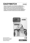
8. ESQUEMA DE INSTALACIÓN DE UN POOLWATCH BASIC CLORO O BROMO ORGÁNICO (VERSIÓN B)
PISCINA
Floculación en continuo
Filtro
Agua de red
Tu b o d e in ye cció n 4 x 6 m m
Intercambiador
Ø 32
Dosificador
de tabletas
Cl/Br
Bomba de recirculación
Vaso de compensación
Ø 32
Cubeta de
seguridad
Depósito
corrector
pH
Desagüe
<<
Tubo 8 x10 mm
<<
Válvula motorizada
Tubo 8 x10 mm
Colocar el depósito del corrector de pH lo más alejado posible de
todos los equipos.
NOTA: Instalar la válvula motorizada lo más separada posible del dosificador de tabletas.
9. ESQUEMA DE INSTALACIÓN DE UN POOLWATCH BASIC CLORO O BROMO ORGÁNICO (VERSIÓN C)
PISCINA
Floculación en continuo
Filtro
Agua de red
Tu b o d e in ye cció n 4 x 6 m m
Intercambiador
Dosificador
de tabletas
Cl/Br
Ø 32
Bomba de recirculación
Vaso de compensación
pH
Ø 32
Cubeta de
seguridad
Depósito
corrector
pH
<<
Tubo 8 x10 mm
<<
Electroválvula
Tubo 8 x10 mm
Desagüe
Colocar el depósito del corrector de pH lo más alejado posible de
todos los equipos.
NOTA: Instalar la electroválvula lo más separada posible del dosificador de tabletas.
5
Ref.33512-cast-R07-V2
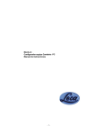
10. DESCRIPCIÓN DEL CONJUNTO PANEL CONTROLADOR POOLWATCH BASIC (33512)
1.- Válvula de entrada de agua D = 20 mm (02453)
2.- Central. (33512A0001)
3.- Tapa del Regletero.
4.-Filtro de asiento inclinado (25713)
5.- Cable conector del electrodo de pH.
6.- Cable conector del electrodo de Redox.
7.- Cámara de Análisis (07995R0004).
8.- Electrodo de pH (32460-0010).
9.- Electrodo de Redox (32460-011).
10.- Cable del equipotencial
11.- Válvula para tomar muestras de agua de ¼” (11656)
12.- Válvula de salida de agua. D = 20 mm (02453)
pH
dosage
Cl/Br
1
2 3 4
5
6
6
7
8 9 10 11 12
Ref.33512-cast-R07-V2
11. DESCRIPCIÓN DEL CONJUNTO PANEL DOSIFICADOR PARA CLORO INORGÁNICO (33514) OPCIÓN A
1.- Panel dosificador PE
2.- Bomba dosificadora para el corrector de pH. (01285)
3.- Bomba dosificadora para el corrector de Cl. (01285)
pH
2
1
Cl
3
12. DESCRIPCIÓN DEL CONJUNTO PANEL DOSIFICADOR PARA CLORO ORGÁNICO/BROMO (33515) OPCIÓN B
1.- Panel dosificador PE
2.- Bomba dosificadora para el corrector de pH. (01285)
3.- Maniobra de la válvula motorizada. (14908R0501)
No fijada al panel:
4.- Válvula motorizada D = 32 mm (02626)
pH
2
3
4
1
7
Ref.33512-cast-R07-V2
13. DESCRIPCIÓN DEL CONJUNTO PANEL DOSIFICADOR PARA CLORO ORGÁNICO/BROMO (33516) OPCIÓN C
1.- Panel dosificador PE
2.- Bomba dosificadora para el corrector de pH. (01285)
No fijada al panel:
3.- Electroválvula 1” (14908R0002)
pH
2
3
1
14. DESCRIPCIÓN DE LA CARÁTULA POOLWATCH BASIC
1 . -DISPLAY LCD: Display retroiluminado que nos indica el valor de pH y su valor de consigna (“set point”) y también nos indica el
valor del potencial Redox en mV y su valor de consigna (“set point”). La flecha, que está a la derecha del valor de consigna;
hacia arriba indica si está utilizando un incrementador y la flecha hacia abajo si está utilizando un minorador.
2 . -TECLADO DE 4 FLECHAS: Mediante estas flechas 2a, 2b, 2c y 2d nos podemos desplazar en el display cuando entremos en
programación. Pulsando la tecla 2a saldrá referencia + versión, y las asimetrías de las lecturas del pH y RedOx; la tecla 2b
saldrá un nº de password; la tecla 2c la temperatura y la 2d las tensiones de señal directa (en mV) y las pendientes del
electrodo de pH y de RedOx.
3.- TECLA ENTER: Se utiliza para entrar en programación y para la misma programación.
4 .- TECLA VAL: Se utiliza para validar.
5 .- TECLA ESC: Se utiliza para salir de programación.
6.- PILOTO pH: Indica, cuando se ilumina, que está activado el relé de la bomba de pH.
7.- –PILOTO Cl/Br: Indica, cuando se ilumina, que está activado el relé de la bomba de Cloro, o la válvula motorizada para el
dosificador de tabletas de Cl o de Br, o la electrovávula para el dosificador de tabletas de Cl o de Br.
15. DESCRIPCION DE LA CARÁTULA POOLWATCH BASIC
POOLWATCH BASIC
6
7
1 2d 2a
8
CONTROL MINOR
2c
2b
3
5
4
Ref.33512-cast-R07-V2
16. PUESTA EN MARCHA, AJUSTE Y CALIBRACIÓN
Es recomendable que antes de la puesta en marcha del PoolWatch Basic tengamos el agua entre 7 - 7.6 unidades de pH y 1
– 1,5 ppm de Cl ó 2 –3 de Br.
1.-
Instalar el equipo y conectarlo a la alimentación eléctrica (230 V ac). Colocar el mando de puesta en marcha de las
bombas dosificadoras en la posición 0 (paro).
En la versión B y C cerrar la entrada de agua al dosificador de tabletas.
2.- Mantener cerradas las válvulas de entrada y salida de agua a la cámara de análisis.
3.- Sacar el electrodo de pH de su envase original.
4.-
Conectar el electrodo de pH al cable conector de la derecha (correspondiente a los bornes 24 malla (-), azul o negro
y 25 Activo (+) translúcido y conectar un cable al borne nº 23 (equipotencial) que posteriormente se introducirá el otro extremo
del cable, en las soluciones tampón pH4, pH7 y 745mV cuando se efectúen las calibraciones.
5.- Llenar el vaso de calibración con solución tampón pH 7. Seguir el diagrama de flujo de la programación del equipo. Ir a ajuste
seleccionando el parámetro de pH. Aparecerá “ In sensor pH7”, es decir introducir el electrodo de pH y el cable del
equipotencial (borne nº 23 y desconectar el cable del borne nº 28) en la solución patrón 7.00 y pulsar ENTER. Aparecerán unas
barras en la pantalla de LCD. Una vez finalizada la calibración con la solución patrón pH 7 el equipo nos mostrará la pantalla “in
sensor pH4”.
6 .- Enjuagar el electrodo de pH con solución tampón pH 4 antes de realizar el ajuste a pH 4.
7.- Llenar el vaso de calibración con solución tampón pH 4. Repetir la misma operación anterior (recordar que se debe introducir el
electrodo de pH y el cable del equipotencial, borne nº 23 y desconectar el cable del borne nº 28, en la solución tampón) , pero
con la solución tampón pH 4.
8.- Al finalizar la calibración de pH 4 pulsaremos la tecla VAL de validar, lo cual confirmará el correcto ajuste del electrodo de pH.
8.- Seguidamente se saca el electrodo del vaso de calibración, tiramos el contenido de éste y colocamos el electrodo
en la zona de ubicación izquierda de la cámara de análisis, desconectando previamente éste del cable de conexión y
volviendo a conectarlo ya ubicado en la cámara de análisis.
9.- Sacar el electrodo de RedOx de su envase original.
10.- Conectar el electrodo de RedOx al cable conector de la izquierda (correspondiente a los bornes 26 malla (-), azul o negro y
27 Activo (+) translúcido
11.-
Llenar el vaso de calibración (previa limpieza y enjuague) de solución tampón 475 mV. Seguir el diagrama de flujo de la
programación del equipo (pág. 11-12). Pulsar ENTER. Ir a ajuste; seguidamente seleccionar el parámetro mV, introducir sensor
mV y el cable del equipotencial (borne nº 23 y desconectar el cable del borne nº 28) en la solución patrón, y volver a pulsar
ENTER. Aparecerán unas barritas en la pantalla pulsando la tecla ENTER. Una vez finalizada la calibración, pulsaremos validar
(VAL), lo cual confirmaría un correcto ajuste del electrodo de RedOx.
12.-
Seguidamente se saca el electrodo del vaso de calibración,
tiramos
el contenido de éste y colocamos el
electrodo en la zona de ubicación derecha de la cámara de análisis, desconectando previamente éste del cable de
conexión y volviendo a conectarlo ya ubicado en la cámara de análisis. Al final se debe de sacar el cable del borne nº 23 y
volver a conectar el cable del equipotencial (unido al extremo final de la cámara) al borne nº 28.
13.- Abrir las válvulas de entrada y salida de agua a la cámara de análisis.
14.- Antes de programar el equipo dejar circular el agua por el interior de la cámara de análisis durante 1/2 h.
Se puede observar en la pantalla del LCD lo siguiente:
Parte superior: Lectura de pH y del Set Point programado. La flecha que aparece en el margen derecho indica si está utilizando
minorador (p) o incrementador (n)
Parte inferior: Lectura de mV y el Set Point programado. La flecha que aparece en el margen derecho indica adición de
desinfectante (n).
16.1 PROGRAMACIÓN DEL pH
1.- El equipo PoolWatch Basic viene comprobado con un valor de ajuste de 7.2 pudiéndose modificar este valor.
2.- Los valores del ajuste de pH están comprendidos entre 6.2 y 7.8, siendo el ideal de 7.2.
3.- El equipo tiene la opción de poder bajar el pH dosificando un minorador o la de subir el pH dosificando un incrementador. Para
ello ver el diagrama de flujo (páginas 11-12), el equipo viene de fábrica para dosificar minorador de pH.
4.- Poner en marcha la bomba dosificadora del regulador de pH seleccionando un porcentaje en el caudal de la bomba, adecuado
a las características de la piscina, una vez el pH esté ajustado a 7.2 se procede a la programación del cloro o del bromo.
9
Ref.33512-cast-R07-V2
ATENCIÓN:
A) En caso de utilizar minorador de pH:
Si el valor del pH resultante después de la dosificación (ajuste) fuese inferior al valor de SET PONT programado (7.2) es señal de
que en la bomba dosificadora del regulador de pH tenemos seleccionado un porcentaje demasiado alto en el caudal de la bomba.
Reducir este porcentaje ajustándolo a las características de la piscina.
B) En caso de utilizar incrementador de pH:
Si el valor del pH resultante después de la dosificación (ajuste) fuese superior al valor de SET PONT programado (7.2) es señal
de que en la bomba dosificadora del regulador de pH tenemos seleccionado un porcentaje demasiado alto en el caudal de la
bomba. Reducir este porcentaje ajustándolo a las características de la piscina.
O al contrario, si estamos dosificando tanto minorador como incrementador de pH y no hay forma de llegar al valor 7,2 es señal de
que el porcentaje seleccionado en el caudal de la bomba es inferior al necesario. Aumentar este porcentaje ajustándolo a las
características de la piscina.
16.2 CALIBRACIÓN DEL ELECTRODO (pH)
Cuando introducimos el electrodo de pH en la solución tampón pH 7 y pH 4 (recordar que también se debe de introducir en esas
soluciones el cable del equipotencial, borne nº 23 y sacar el cable unido al borne nº 28), puede ocurrir que la lectura de calibración
esté muy desviada y aparezca estado del electrodo incorrecto. Introducir el electrodo en la solución limpiadora durante 2 minutos y
repetir la calibración. En caso de que persista esa desviación, proceder a cambiar el electrodo.
Si no se dispone de un electrodo nuevo, deberá tener en cuenta que aunque se pueda calibrar tendrá una gran desviación en
cuanto a la lectura real, por lo que es muy probable que se desajuste en pocas horas.
16.3 CALIBRACIÓN DEL ELECTRODO (mV)
Cuando introducimos el electrodo de mV en la solución 475 mV (recordar que también se debe de introducir en esas soluciones el
cable del equipotencial, borne nº 23 y sacar el cable unido al borne nº 28), puede ocurrir que la lectura de calibración esté muy
desviada y aparezca estado del electrodo incorrecto. Introducir el electrodo en la solución limpiadora durante 2 minutos y repetir la
calibración. En caso de que persista esa desviación, proceder a cambiar el electrodo.
Si no se dispone de un electrodo nuevo, deberá tener en cuenta que aunque se pueda calibrar tendrá una gran desviación en
cuanto a la lectura real, por lo que es muy probable que se desajuste en pocas horas.
16.4 PROGRAMACIÓN DEL CLORO O DEL BROMO
1.- El equipo PoolWatch Basic viene de fábrica con un valor de Set Point programado de 750 mV.
2.- Tenemos la posibilidad de ajustar el valor de mV de 0 a 999 mV (para ello ver el diagrama de flujo páginas 11-12).
3.- Poner en marcha la bomba dosificadora de Cl/Br, seleccionando un porcentaje en el caudal de la bomba, adecuado a las
características de la piscina (Versión A).
4.- Abrir la válvula de entrada de agua al dosificador de tabletas para que cuando entre en funcionamiento la válvula motorizada
pueda pasar agua a través del dosificador. Colocar dentro de éste el número de tabletas correspondiente al volumen de la
piscina a tratar y al número de usuarios. (Ver instrucciones del dosificador, versiones B y C).
5.- Una vez ajustado el nivel de Cl ó Br, si el nivel de Cl ó Br no es suficiente (hacer análisis del agua de la piscina), entraríamos en
programación en equipo, nos iríamos al SET POINT (SP), seleccionaríamos el parámetro mV mediante las teclas
correspondientes. Seguidamente introduciríamos un valor de SET POINT superior al que tenemos, y pulsaríamos la tecla
ENTER, volviendo al inicio del diagrama de flujo (página 12). De esta forma aumentaríamos el nivel de cloro presente en el
agua.
6.- De forma análoga, en el caso de que el nivel de Cl o Br sea superior al deseado, entraríamos en programación de la misma
forma que se ha escrito anteriormente, hasta llegar al valor de SET POINT, el cual sería modificado por un valor más bajo:
Pulsaríamos ENTER, volviendo al inicio del diagrama de flujo (páginas 11- 12).
Si el nivel de cloro aun así fuera alto, repetiríamos la operación hasta que se consiga el nivel deseado.
10
Ref.33512-cast-R07-V2
ATENCIÓN:
Si el valor del cloro o bromo resultante después de la dosificación fuese superior al valor programado (ver pantalla LCD) es señal
en la:
VERSION (A) PoolWatch Basic Cloro Inorgánico: La bomba dosificadora del cloro tiene un porcentaje demasiado alto en el
caudal de la bomba. Por lo tanto tendremos que reducir este porcentaje.
VERSION (B y C) PoolWatch Basic Cl ó Br Orgánco: La válvula de entrada de agua al dosificador de tabletas está demasiado
abierta o la carga de tabletas en el interior del dosificador es demasiado grande. Por lo tanto tendremos que cerrar algo la
válvula de entrada de agua al dosificador o reducir la carga de tabletas de su interior.
O al contrario, si estamos dosificando y no hay forma de llegar al valor programado es señal en la:
VERSION (A) PoolWatch Basic Cloro Inorgánico: La bomba dosificadora del cloro tiene un porcentaje demasiado bajo en el
caudal de la bomba. Por lo tanto, tendremos que aumentar este porcentaje.
VERSION (B y C) PoolWatch Basic Cl ó Br Orgánco: La válvula de entrada de agua al dosificador de tabletas está poco
abierta o la carga de tabletas en el interior del dosificador es pequeña. Por lo tanto, tendremos que abrir más la válvula de entrada
de agua al dosificador o aumentar la carga de tabletas en su interior.
17. DIAGRAMAS DE FLUJO DE LA PROGRAMACIÓN DEL POOLWATCH BASIC
DIAGRAMA DE FLUJO RESTRINGIDO SELECCIÓN pH
PpH: 7.6
P mV: 650
SP:7.2
SP:750
Enter
Sel. de entrada
P[ pH ]
mV
Enter
Programación
P[ sp ] ºC ajuste
Enter
Tipo corrector
P[ Minus ] Plus
Programación
Programación
P sp [ºC ] ajuste
P sp ºC
[ ajuste ]
Enter
Enter
Enter
CpH Set point
sp: 7.2
Menú Temperatura
[ manual ] sensor
Enter
Enter
Actualizando
Mem. Datos
Intr. Temperatura
Temp: 25.0 ºC
Intr. sensor pH7
Pulsar Enter
Enter
Cal pH L:7.02
Menú Temperatura
Manual [ sensor ]
Intr. sensor pH4
Pulsar Enter
Enter
Cal pH L:4.02
*No Correct*
Pulsar VAL
11
*Correcto*
Pulsar VAL
Ref.33512-cast-R07-V2
DIAGRAMA DE FLUJO RESTRINGIDO SELECCIÓN mV
PpH: 7.6 SP:7.2
PmV: 650 SP:750
Enter
Sel. de entrada
P[ pH ]
mV
Sel. de entrada
P pH [ mV]
Enter
Programación
P[ sp ] ajuste
Enter
Tipo corrector
P[ Desinf ] Neutra
Programación
P sp [ ajuste ]
Enter
Enter
Intr. sensor 475mV
Pulsar Enter
CmV Set point
sp: 750
Enter
Enter
Cal pH L: 480
Actualizando
Mem. Datos
*No Correct*
Pulsar VAL
*Correcto*
Pulsar VAL
DIAGRAMA DE FLUJO PARA ACCEDER A LOS PROGRAMAS NO RESTRINGIDOS
PpH: 7.6
P mV: 650
SP:7.2
SP:750
Intr. Password
P >: 0000
Intr. Password
P >: 0100
Enter
Password usuario
P[ no ]
si
Enter
Detector caudal
P[ no ]
si
Enter
Cselec idiomas
-Castellano
Enter
Cacceso limitado
P no
[ si ]
Cacceso limitado
P [ no ]
si
Enter
Actualizando
Mem. Datos
12
Ref.33512-cast-R07-V2
DIAGRAMA DE FLUJO NO RESTRINGIDO SELECCIÓN pH
PpH: 7.6
P mV: 650
SP:7.2
SP:750
Enter
Sel. de entrada
P[ pH ]
mV
Enter
Programación
P[ sp ] ºc ajuste
Enter
Control pH
P[ relé ] 4-20mA
Programación
Programación
P sp [ºc ] ajuste
P sp ºC
[ ajuste ]
Enter
Enter
Intr. sensor pH7
Pulsar Enter
menú Temperatura
[ manual ] sensor
Enter
Cal pH L:7.02
Enter
Intr. Temperatura
Temp: 25.0 ºC
Menú Temperatura
Manual [ sensor ]
Intr. sensor pH4
Pulsar Enter
Enter
Enter
Cal pH L:4.02
Enter
Control relé
[ on/off ] prop
Control pH
Enter
[ prop ]
Enter
Enter
Control pH
[Lectura ] Dosif
Banda propor. CpH
C ud/pH: 01.00
Enter
Tipo corrector
Ccontrol pH
Lectura [Dosif ]
Intr. Consigna pH
[ minus] plus
Enter
*Correcto*
Pulsar VAL
P relé [ 4-20 mA ]
Control relé
On/off
*No Correct*
Pulsar VAL
C ud/pH: -0.00
Tipo corrector
Enter
Enter
C minus [plus]
Span input pH
CpH set point
sp: 7.2
C ud/pH: 00.00
Enter
Enter
Actualizando
Mem. Datos
13
Ref.33512-cast-R07-V2
DIAGRAMA DE FLUJO NO RESTRINGIDO SELECCIÓN mV
PpH: 7.6
P mV: 650
SP:7.2
SP:750
Enter
Sel. de entrada
P[ pH ]
mV
Sel. de entrada
P pH
[ mV ]
Enter
Programación
P[ setp ]
ajuste
Enter
Enter
Programación
P setp
Control mV
P[ relé ] 4-20mA
[ ajuste ]
Enter
Intr. sensor 475mV
P pulsar Enter
Enter
Cal mV L: 480
*No Correct*
Pulsar VAL
*Correcto*
Pulsar VAL
Enter
Control relé
[ on/off ] prop
Control relé
On/off [ prop]
Enter
Enter
Banda propor.CmV
Cud/pH: 0100
Tipo corrector
[Desinf ] Neutra
Enter
Ccontrol mV
Prelé [ 4-20 mA ]
Enter
Ccontrol mV
[Lectura ] Dosif
Enter
Intr. Consigna mV
ud/pH: 000
C
Tipo corrector
Desinf [Neutra ]
Ccontrol mV
Lectura [Dosif ]
Enter
Enter
Span input mV
ud/mV: 00.00
C
CmV set point
sp: 750
Enter
Enter
Actualizando
Mem. Datos
14
Ref.33512-cast-R07-V2
18. ESQUEMA DEL REGLETERO DE LOS BORNES
19. LEYENDA DEL ESQUEMA DEL REGLETERO DE LOS BORNES
1 2 3
Alimentación 230 V ac 50/60 Hz (+ toma de tierra) de la central. Esta conexión la debe realizar el instalador.
4 5 3
Alimentación 230 V ac 50/60 Hz (+ toma de tierra) de las bombas dosificadoras. Esta conexión la debe realizar el
instalador.
11 12
Contacto libre de tensión (N.O.) del contactor de la bomba de filtración. Así se consigue que las bombas dosificadoras y
válvula motorizada funcionen únicamente cuando la filtración de la piscina esté en funcionamiento. Deben llevar el borne
nº 11 al contacto abierto del contactor de la bomba de filtración y de salida de éste al borne nº 12. Estas conexiones
las debe realizar el instalador.
6 7
Salida 230 V ac para la bomba dosificadora de pH.
8 9
Salida 230 V ac para la bomba dosificadora de cloro o válvula motorizada del dosificador.
10 11 12 Conexión con el detector de caudal, (10- 11E 12+) o para la conexión del fluxómetro 11E 12E+.
13 al 16 Conexión comunicaciones RS-485
17 18
Salida proporcional pH para registrador o dosificación para bomba dosificadora (Opcional)
19 20
Salida proporcional mV para registrador o dosificación para bomba dosificadora o válvula motorizada proporcional
(Opcional)
21 22
Sensor de temperatura PT-100
23
Equipotencial para calibración de los electrodos
24 25
Conexión del electrodo de pH (24 malla – negro 25 activo - translúcido)
26 27
Conexión del electrodo de mV (26 malla – negro 27 activo - translúcido)
28
Equipotencial.
20. ESQUEMA DE CONEXIÓN DE LA MANIOBRA DE LAS VÁLVULAS MOTORIZADAS PARA POOLWATCH BASIC
20.1 ESQUEMA DE CONEXIÓN DE LA MANIOBRA DE LAS VÁLVULAS MOTORIZADAS, CON BLOQUE DE SEGURIDAD,
PARA LOS EQUIPOS POOLWATCH BASIC
1 2 8
1
2
3
CONECTOR
DE MANIOBRA
DE LA VÁLVULA
MOTORIZADA
15
Ref.33512-cast-R07-V2
20.2 ESQUEMA DE CONEXIÓN DE LA MANIOBRA DE LAS VÁLVULAS MOTORIZADAS, SIN BLOQUE DE SEGURIDAD,
PARA LOS EQUIPOS POOLWATCH BASIC
CAJA DE CONEXIÓN
Conexión al borne 9 del regletero
A2
L1 es fase F
L2 es neutro N
Entrada de tensión
directa 230 v ac
L1
L2
M1 M2 M3
A1
Salida Válvula
motorizada
Conexión al borne 8 del regletero
1
2
3
Esquema eléctrico de
la válvula motorizada
21. MANTENIMIENTO DE LOS ELECTRODOS
PUESTA EN SERVICIO
Antes de utilizar los electrodos, comprobar que estén libres de incrustaciones, suciedades o cristalizaciones. En el caso de que
los electrodos presentaran alguna de estas anomalías, introducirlos en solución limpiadora durante 2 minutos.
LIMPIEZA Y ENTRETENIMIENTO DE LOS ELECTRODOS
Sométanse los electrodos de medición a inspecciones oculares (aprox. 1 vez al mes) y efectúese su limpieza en caso necesario.
Para realizar la limpieza de los electrodos, sumergirlos en la solución limpiadora, únicamente el extremo del electrodo (membrana
de vidrio) durante 2 minutos. Sería imprescindible que después de cada limpieza los electrodos se introdujeran en solución
conservadora de KCl 3 M durante 5 minutos.
Limpieza y entretenimiento del filtro 1 vez por semana con agua a presión.
ALMACENAMIENTO
Verificar que durante su almacenamiento los electrodos de pH y RedOx tengan en el extremo final de los mismos (zona
humedecida) el líquido de solución conservadora KCl 3 M que viene de fábrica .En el caso de su evaporación o pérdida
accidental, verter un poco de solución KCl trimolar en la caperuza o carcasa protectora. Es imprescindible que la caperuza
o carcasa protectora siempre esté humedecida con dicha solución.
Las condiciones de almacenaje deben de ser en lugar seco entre temperaturas entre 10ºC hasta 30ºC. Temperaturas de
–15ºC pueden fracturar los electrodos o desnaturalizar el electrolito
: Los electrodos de pH y RedOx no pueden almacenarse por tiempo indefinido. Por consiguiente no se
recomienda almacenarlos durante más de tres meses.
16
Ref.33512-cast-R07-V2
: No poner los electrodos al remojo con agua destilada, ya que esto sería causa de un envejecimiento
prematuro e irreversible.
: No manipular el extremo de los electrodos, donde se conectan el cable, con las manos mojadas porque
podría producir un cortocircuito y deteriorar rápidamente el electrodo de referencia y por lo tanto, la vida de
los electrodos.
VIDA ÚTIL
Los electrodos de pH y RedOx están sometidos a un envejecimiento natural, aun cuando se manejen reglamentariamente de
acuerdo con el empleo que se les dé. La vida útil previsible oscilará entre medio año y un máximo de dos años.
(Los electrodos de pH y Redox son materiales perecederos, por lo que no disponen de garantía).
PERIODICIDAD DE LAS CALIBRACIONES
Es recomendable verificar periódicamente (1 vez al mes) mediante kits de análisis o fotómetro los valores de pH y las ppm de Cl o
Br y compararlos con los que se visualizan en el display del equipo. Si existieran grandes diferencias debería de repetir los análisis
para asegurarse de las diferencias. En caso afirmativo debería procederse a efectuar las calibraciones de los electrodos de pH y
del potencial RedOx.
La existencia de diferencias entre los resultados analíticos y los valores que se visualizan en el display puede ser debidos a las
condiciones físico químicas que se ha sometido el agua de la piscina, como por ejemplo tratamientos manuales de hipercloración;
adición manual de algicidas; adición manual de floculante, etc. Otro motivo de esas diferencias puede ser debido a la propia calidad
físico química del agua de aportación al vaso de la piscina.
ADICIÓN DE PRODUCTOS QUÍMICOS
Cuando se efectúen operaciones, como la adición manual de productos químicos o limpieza de filtros, se recomienda que durante
este proceso se aisle el equipo, cerrando las válvulas de entrada y de salida al equipo, para prever cualquier accidente o entrada
de productos no deseables a la cámara de análisis y de esta manera no se altere, ni contamine los electrodos.
22. TABLA RESUMEN DE PROBLEMAS, CAUSAS Y SOLUCIONES
ANOMALIAS
CAUSAS
SOLUCIONES
Nivel de pH por encima del valor
programado (si se usa
incrementador)
Seleccionó un % de la bomba dosificadora
más alto del adecuado.
Reducir el % ajustándolo a las
características de la piscina.
Nivel de pH por debajo del valor
programado (si se usa minorador)
Seleccionó un % de la bomba dosificadora
más alto del adecuado.
Reducir el % ajustándolo a las características
de la piscina.
Nivel de Cloro por encima del valor
programado.
Versión A: (PoolWatch Cl Inorgánico)
La bomba dosificadora de cloro tiene un %
más alto del adecuado.
Versión A: (PoolWatch Cl Inorgánico)
Reducir el % ajustándolo a las
características de la piscina.
Versión B y C: (PoolWatch Cl ó Br
Orgánico
La válvula de entrada de agua al dosificador
de tabletas está demasiado
abierta o la carga de tabletas en el interior del
dosificador es demasiado grande.
Versión B y C: (PoolWatch Cl ó Br
Orgánico)
Cerrar algo la válvula de entrada de agua al
dosificador o reducir la carga de tabletas en
su interior.
Versión A: (PoolWatch Cl Inorgánico)
La bomba dosificadora de cloro tiene un %
demasiado bajo
Versión A: (PoolWatch Cl Inorgánico)
Aumentar el % ajustándolo a las
características de la piscina.
Versión B y C: (PoolWatch Cl ó Br
Orgánico)
La válvula de entrada de agua al dosificador
de tabletas está poco abierta o la carga de
tabletas en el interior del dosificador es
pequeña.
Versión B y C: (PoolWatch Cl ó Br
Orgánico)
Abrir más la válvula de entrada de agua al
dosificador o aumentar la carga de tabletas
en su interior.
Nivel de Cloro por debajo del valor
programado.
17
Ref.33512-cast-R07-V2
a)
No se ha efectuado la conexión de los
bornes 11 y 12 del regletero de conexión con
un contacto libre de tensión del contactor de
la bomba de filtración (ver página 15).
No se ha efectuado la alimentación 4 y 5
para las bombas dosificadoras o válvula
motorizada o electroválvula (ver página 15).
b)
Filtración parada
a)
Efectuar la conexión de los bornes 11 y 12
del regletero de conexión con un contacto
libre de tensión del contactor de la bomba de
filtración.
Efectuar la conexión 4 y 5 para las bombas
dosificadoras o válvula motorizada o
electroválvula.
b)
Si la filtración está en automático esperar a
que se ponga en marcha según la hora
prefijada, o bien poner la filtración en marcha
en forma manual.
La válvula motorizada no abre y el
relé está activado.
Mala conexión.
Revisión de la conexión eléctrica. (Ver
esquemas Páginas 15-16 ).
El análisis físico-químico del agua
de la piscina, concretamente el pH y
nivel de Cl, no se corresponden con
la lectura del Control (Existe mucha
diferencia)
a) Filtro cartucho sucio
a) Limpiar.
Led indicador de la conexión a la
bomba dosificadora de pH ó Cl, o
de la conexión a la válvula
motorizada iluminado (activado), sin
que esté dosificando la bomba
dosificadora correspondiente o sin
que esté abierta la válvula
motorizada.
Parpadea la lectura de pH y/o mV
que aparecen en el LCD
b) Electrodos sucios.
b) Limpiarlos con solución limpiadora.
c) Electrodos agotados.
c) Cambiarlos.
Desajuste de los electrodos de pH y/o mV
Volver a calibrar
23. CARACTERISTICAS TECNICAS DE LOS EQUIPOS POOLWATCH BASIC
- Rango de medida pH: 0.0 a 14.0 (resolución: 0.1 unidad)
- Rango Set Point pH: 0-14
- Rango de medida mV: 0 a 1200 (resolución: 1 mV)
- Rango Set Point potencial Redox (mV): 0 a 999 mV.
- Timer retardo: 0-100 segundos (10 s).
- Calibración a pH 7 y pH 4.
- Consumo eléctrico del equipo: 50 W + consumo de las bombas dosificadoras
- Tensión de alimentación: 230 V Monofásico + Tierra, 50 Hz
- Salida analógica 4-20 mA carga máxima 250 Ohmmios
- Comunicaciones: RS-232/RS-485: protocolo abierto
- Temperatura (opcional) PT-100: 00-99 ºC
FICHA TECNICA CONTROL POOLWATCH BASIC
- Controlador y/o regulador de pH y/o potencial Redox.
- Visualización por Display LCD retroiluminado alfanumérico (16 caracteres)
- Convertidor ADC de 16 bits con referencia compensada de Tª + filtrado digital
de lectura para alta inmunidad a interferencias.
- Microprocesador de 16 bits.
- 2 Salidas ON / OFF (Relés) de regulación (contactos libres de tensión).
- Programación multiidioma.
- Aviso de electrodo defectuoso en calibración.
18
Ref.33512-cast-R07-V2
24. RECAMBIOS DEL POOLWATCH BASIC (33512)
Nº
1
2
3
4
5
6
7
8
9
10
11
CÓDIGO
33512A0001
07955-0501
07955R0004
32460-0010
32460-0011
32460-0800
07955-0502
07955R0010
07955R0011
07955R0012
16644-0400
DESCRIPCIÓN
Central PoolWatch Basic
Circ uito agua primer tramo V-M
Cámara análisis de metac rilato
Electrodo combinado pH 251
Electrodo combinado RedOx 351
Cable equipotencial EJ
Circ uito agua segundo tramo V-M
Solución patrón pH 7
Solución patrón pH 4
Solución patrón RedOx 475 mV
Bolsa racords azules 2 unidades
8
pH
07955R0010
Solución patrón pH7
dosage
Cl/Br
9
07955R0011
Solución patrón pH4
10
07955R0012
Solución patrón
RedOx 475 mV
16644-0400
Bolsa racords azules
2 unidades
1
2
3
4
19
5
6
7
Ref.33512-cast-R07-V2
11
25. GRÁFICA ORIENTATIVA QUE RELACIONA LAS CONCENTRACIONES DE CLORO CON EL POTENCIAL REDOX Y EL pH
Estas curvas son orientativas, relacionan las concentraciones de cloro con el pH y el potencial RedOx. Pueden verse
influenciadas por la calidad del agua: la concentración de las sales disueltas, la temperatura, la cantidad de materia orgánica
(TOC), la concentración de cloro combinado, la presencia de ácido isocianúrico, los subproductos de la cloración, etcétera.
20
Ref.33512-cast-R07-V2
POOLWATCH BASIC
pH/mV
33512
Sodium hypoclorite, solid chlorine
tablets and bromine tablets
Installation and Maintenance Manual
1
Ref: 33512-gb-R011
ÍNDEX
pages
1. Versions PoolWatch Basic ..........................................................................................................................................3
2. PoolWatch Basic Components (33512) .......................................................................................................................3
3. PoolWatch Basic Components Inorganic Chlorine Version A (33514) .....................................................................3
4. PoolWatch Basic Components Organic Chlorine/Bromine Version B (33515)........................................................3
5. PoolWatch Basic Components Organic Chlorine/Bromine Version C (33516)........................................................4
6. PoolWatch Basic installation........................................................................................................................................4
7. PoolWatch Basic Inorganic Chlorine diagram (Version A).........................................................................................4
8. PoolWatch Basic Organic Chlorine/ Bromine diagram (Version B).........................................................................5
9. PoolWatch Basic Organic Chlorine/ Bromine diagram (Versión C)..........................................................................5
10. Outfit description automatic and control panel PoolWatch Basic (33512) .............................................................6
11. Outfit description Inorganic Chlorine dispenser panel PWB (33514) Option A ......................................................7
12. Outfit description Organic Chlorine/Bromine dispenser panel PWB (33515) Option B ........................................7
13. Outfit description Organic Chlorine/Bromine dispenser panel PWB (33516) Option C ........................................8
14. Power plant description PoolWatch Basic.................................................................................................................8
15. Power plant diagram PoolWatch Basic ......................................................................................................................8
16. Starting, adjusting and calibration...............................................................................................................................9 - 11
16.1. pH Programming ..............................................................................................................................9 - 10
16.2. Probe calibration pH ........................................................................................................................10
16.3. Probe calibration ORP ( mV) ...........................................................................................................10
16.4. Chlorine/Bromine programming .....................................................................................................10-11
17. Flow diagram of PoolWatch Basic ..............................................................................................................................11 - 14
18. Terminal strip diagram .................................................................................................................................................15
19. Legend of the terminal strip diagram..........................................................................................................................15
20. Manoevre connection of motorised ball valve for PoolWatch Basic .......................................................................15 - 16
20.1 Connection of motorized ball valve with con safety block ............................................................................15
20.2 Connection of motorized ball valve .................................................................................................................16
21. Probes maintenances...................................................................................................................................................16-17
22. Summary dra. Problems, casues and solutions ........................................................................................................17-18
23. Technical specifications of PoolWatch Basic............................................................................................................18
24. Spare parts PoolWatch Basic (33512) ........................................................................................................................19
25. Draw ORP-pH-ppm Free Chlorine ................................................................................................................................20
2
Ref. 33512-gb-R11
1. VERSIONS POOLWATCH BASIC
PoolWatch Basic is an equipment which can automatically control and regulate the dosage of the disinfecting product (chlorine or
bromine) and pH regulation (increaser or reducer) in the water of the swimming pool.
This is unic panel regulations and control, Panel PoolWatch Basic (33512) and the after there are trhee dispenser panels:
PoolWatch Basic Inorganic Chlorine (33514): (Version A): Wich is used to work with liquid chlorine (sodium hypochlorite). And
incluyes two dosage pumps.
PoolWatch Basic Organic Chlorine/Bromine (33515) (Version B): Wich is used to work with chlorine or bromine tablet; it includes
a dosage pump and a motorised valve to 230V 50Hz, with the manoeuvre set.
PoolWatch Basic Organic Chlorine/Bromine (33516) (Version C): Wich is used to work with chlorine or bromine tablet; it includes
a dosage pump and a valve electrical normaly closed to 230 V 50 Hz.
2. POOLWATCH BASIC COMPONENTS (33512)
- Transmitter.
- Analisy chamber.
- Line strainer
- Valve fir water samples
- pH probe with the jumping cables.
- ORP probe with the jumping cables.
- Two probe jumping cables.
- pH 4 buffer solution.
- pH 7 buffer solution.
- 475 mV buffer solution.
- Interconnector and reducing pipe for test chamber inlet and outlet.
- Control Minor outfit bearing panel.
- Assembling outfit (screws, blocks and spacers).
- Set of instructions.
3. POOLWATCH BAS IC COMPONENTS Inorganic Chlorine (33514) Version A
- pH corrector dosage pump, spare parts includes.
- Chlorine dosage pump, spare parts includes.
- Dosage pumps panel.
- Assembling outfit (screws, blocks and spacers).
4. POOLWATCH BASIC COMPONENTS Organic Chlorine / Bromine (33515) Version B
- pH corrector dosage pump, spare parts includes.
- Motorised valve.
- Electrical manoevre for the motorised valve.
- Dosage pump and electrical manoevre panel.
- Assembling outfit (screws, blocks and spacers).
5. POOLWATCH BASIC COMPONENTS Organic Chlorine / Bromine (33516) Versión C
3
Ref. 33512-gb-R11
- pH corrector dosage pump, spare parts includes.
- Electrical valve stainless steel inox AISI-316 1”.
- Dosage pump and electrical manoevre panel.
- Assembling outfit (screws, blocks and spacers).
6. POOLWATCH BASIC INSTALLATION
1.
Fix the two Control Minor outfit panels to the wall with the screws, blocks and spacers supplied.
2.
A minimum distance of 20 cm between the two panels should be kept.
3.
3.- Connect POOLWATCH BASIC outfit to 230V ac electrical feeding with earth connection to points of connection number 1
(Phase), number 2 (Neutral) and number 3 (earth) of the electrical connections of the equipment (it must not depend on
filtering running). Install a 4A bipolar 230V ac thermic magneto. Besides it has to of another electrical nourishment connects
230Vac with capture earth, for the dosing pumps and / or electrical valve or become motorized valve, to the points of
connection number 4 (Phase), number 5 (Neutral) and number 3 (Earth) of the connectors of the equipment. An exterior
thermic magneto of 4 A must to you install to two-pole 230 V.ac. to protect the equipment of the dosing pumps.
NOTE: Earth connection should be independent. Do not connect outfit where electromotors or electrical receivers have been
connected. It could cause jamming, which may damage the outfit.
4.- Connect tags number 11 and number 12 of the terminal strip with a free tension switch in the filtering pump contactor (see
terminal strip diagram).
4.
Connect to the power plant in Version A the dosage pumps and in the Version B the dosage pump and the Electrical
manoeuvre of the motorised valve (see diagram, terminal strip and Versions A, B and C drawings).
5.
Make hydraulic installation (water inlet and outlet into test chamber) according to installation diagram.
NOTE: When the installation has no compensation tumbler, POOLWATCH BASIC water return can be sent to drainage or, let it in
the return pipe of filtered water, always before chlorine and pH injection.
7. POOLWATCH BASIC INORGANIC CHLORINE INSTALLATION DIAGRAM (VERSION A)
Swimmingpool
Filter
Heat Exchanger
M ín 30 cm
Continnous Flocculation
Net water
Mín 20 cm
Pump recirculation
ASTRALPOOL
pH
regulator
tank
Chlorine
tank
Safety tank
Safety tank
<<
Pipe PE 8 x10 mm
<<
In je ctio n p ip e s P E
4 x 6 mm
Balance tank
Pipe PE 8 x10 mm
Desagüe
DO NOT CHEMICAL PRODUCTS TANKS UNCER DOSAGE PUMPS CHEMICAL PRODUCTS
MUST BE SEPARATED FROM DOSAGE PUMPS AND FROM POOLWATCH BASIC OUTFIT
8. POOLWATCH BASIC ORGANIC CHLORINE BROMINE INSTALLATION DIAGRAM (VERSIÓN B)
4
Ref. 33512-gb-R11
Swimminpool
Continuous flocculation
Mín 3 0 cm
Filter
Net water
Heat exchange
In je ctio n p ip e s 4 x 6 m m
Tablets dispenser
Cl/Br
Ø 32
Recirculation pump
Balance tank
pH
Ø 32
Safety tank
PH
regulator
Tank
<<
Pipe PE 8 x10 mm
<<
Motorised valve
Drain Water
Locate pH regulator as separed as possible from all outfits.
Pipe 8 x10 mm
NOTE: Install motorised valve as separed as possible from tablets in horizontal position.
9. POOLWATCH BASIC ORGANIC CHLORINE BROMINE INSTALLATION DIAGRAM (VERSIÓN C)
Swimminpool
Continuous flocculation
Mín 3 0 cm
Filter
Net water
Heat exchange
In je ctio n p ip e s 4 x 6 m m
Tablets dispenser
Cl/Br
Ø 32
Recirculation pump
Balance tank
pH
Ø 32
Safety tank
PH
regulator
Tank
<<
Pipe PE 8 x10 mm
<<
Valve electrical
Drain Water
Locate pH regulator as separed as possible from all outfits.
Pipe 8 x10 mm
NOTE: Install valve electrical as separed as possible from tablets in horizontal position.
5
Ref. 33512-gb-R11
10. OUTFIT DESCRIPTION AUTOMATIC AND CONTROL PANEL POOLWATCH BASIC (33512)
1.
Inlet valve of water D = 20 mm (02453)
2.
Transmitter (33512A0001)
3.
Terminal strip cover
4.
Line strainer D20 (25713)
5.
pH and ORP probe jumping cable
6.
ORP probe jumping cable
7.
Chamber analysis (07995R0004)
8.
pH probe (32460-0010)
9.
Redox probe (32460-0011)
10.
Equipotential cable
11.
Valve for ¼ water samples (11656)
12.
Water outlet valve D=20 mm (02453)
pH
dosage
Cl/Br
1
2 3 4
5
6
7 8 9 10 11 12
11. OUTFIT DECRIPTION INORGANIC CHLORINE INORGANIC CHLORINE DISPENSER PANEL (33514) OPTION A
6
Ref. 33512-gb-R11
1.- .- Dispenser panel PE
2.- Dosage pump pH corrector. (01285)
3.- Dosage pump Cl inorganic. (01285)
pH
2
1
Cl
3
12. DESCRIPCIÓN DEL CONJUNTO PANEL DOSIFICADOR PARA CLORO ORGÁNICO/BROMO (33515) OPCIÓN B
1.- Panel dosificador PE
2.- Bomba dosificadora para el corrector de pH. (01285)
3.- Maniobra de la válvula motorizada. (14908R0501)
No fijada al panel:
4.- Válvula motorizada D = 32 mm (02626)
pH
2
3
4
1
13. OUTFIT DECRIPTION INORGANIC CHLORINE ORGANIC CHLORINE OR BROMINE DISPENSER PANEL (33516) OPTION
C
7
Ref. 33512-gb-R11
1.- Dispenser panel PE
2.- Dosage pump pH corrector. (01285)
Not fixed to the panel:
3.-Electrical valve 1” 230V ac (14908R002)
pH
2
3
1
14. POWER PLANT DECRIPTION POOLWATCH BASIC
1 . -DISPLAY LCD: Back lightened display that shows the pH value and its set point value. It also shows the mV value and its set
point value. The arrow to the right of the set point value shows if an pH enhancer is being used when it is upwards and it is
downwards, shows that a pH reducer
2 . -4 ARROW KEYBOARD: We can move in the display through these arrows when we enter the programme. Touching the key 2a
it will go out it indexes + version, and the asymmetries of the readings of the pH and RedOx; the key 2b will go out one number
of password; the key 2c the temperature and it 2d the tensions of direct sign (in mV) and the slopes of the electrode of pH and of
ORP.
3.- TECLA ENTER: It is used to enter the programme and for the programme itself.
4 .- TECLA VAL: Se utiliza para validar.
5 .- TECLA ESC: It is used to validate.
6.- PILOTO pH: When it is enlighted, it shows that the pump relay is switched on.
7.- –PILOTO Cl/Br: I When it is enlightened, it shows that the Chlorine pump o valve motorised o valve electrical relay is switched
on.
For the tablets dosing of Cl or Br.
15. POWER PLANT DIAGRAM POOLWATCH BASIC
POOLWATCH BASIC
6
7
1 2d 2a
CONTROL MINOR
2c
2b
3
5
4
16. STARTING, ADJUSTING AND CALIBRATION
8
Ref. 33512-gb-R11
It is advisable that before the starting of the PoolWatch Basic we have the water between 7 - 7.6 units of pH and 1 - 1,5
ppm Cl or 2-3 ppm Br.
1.- Place starting gear of measuring pumps in 0 position (stop).In version B, close water inlet into tablets dispenser. In the version B
and C to close the water entry to the tablets dosing.
2.
Keep inlet and outlet valves closed to test analysis chamber.
3.
Take pH probe out of its original container.
4.
Connect the pH electrode to right hand jumping cable (corresponding to 24 heald tag, black (-) and to 25 Active (+) translucent
And a cable connects to the point number 23 (equipotential) that later will interfere another end of the cable, in the buffer
solutions pH4, pH7 and 475mV when the calibrations are effected.
5.- Fill calibration vase of buffer solution pH 7. Introduce the pad solution in the lower part of the pad solution. Follow flow diagram
of outfit programming.. Go to “adjust” and select pH parameter. Introduce “pH sensor” and press ENTER. It is to say to introduce
the pH probe and the cable of the equipotential (point number 23 and boss disconnects the cable of the point number 28) in the
buffer solution 7.00 and press ENTER. Some small bars will appear in the LCD display. Once finished the calibration with the
buffer solution pH 7 the equipment will show us the screen " in sensor pH4 ".
6 .- Wipe pH probe with pH 4 pad solution before adjust to pH 4.
7.-
Fill calibration vase of buffer solution pH 4. Repeat the last process but with buffer solution pH 4 (To remember that it is
necessary to to introduce the pH probe and the cable of the equipotencial, point number 23 and disconnect the cable of the
point number 28, in the buffer solution), but with the buffer solution pH 4.
8.- When the calibration finishes of pH 4 we will touch the key VAL of validar, which will confirm the correct adjustment of the pH
probe.
9.-
Next, take the electrode out of calibration vase, pour its content and place electrode on the right hand side of the test chamber
location, previously disconnecting it from the jumping cable and connecting it again, already located in the test chamber.
10.-
Take ORP electrode out of its original container.
11.- Connect ORP probe to jumping cable on the left hand side (corresponding to plugs 26 heald, black (-) and 27 Active (+)
translucent).
12.- Fill calibration vase (previous cleanliness and rinsing) of buffer solution 475 mV. To follow the flow chart of the programming
of the equipment (page 11-12). To touch ENTER. To go to adjustment; after to select the parameter mV, to introduce sensor mV
and the cable of the equipotencial (point n º 23 and boss to disconnect the cable of the point n º 28) in the solution, and to return
press ENTER. A few small bars will appear in the LCD display. Once finished the calibration, we will pulsate validar (VAL),
which would confirm a correct adjustment of ORP probe.
13.-
Next, take the electrode out of calibration vase, pour its content and place electrode on the right hand side of the test
chamber location, previously disconnecting it from the jumping cable and connecting it again, already located in the test
chamber. Ultimately the cable of the point must to you extract number 23 and return to connect the cable of the equipotential
(joined the final end of the analysis chamber) to the point number 28.
14.- Open inlet and outlet valves to test analysis chamber.
11. Before programming the outfit, let water should circulate inside the test chamber for about ½ hour.
In the LCD display it will appear:
Upper Part: Reading of pH and Set Point programmed. The arrow on the right side indicates if we use a decreaser ( p) or an
increaser (n).
Lower part: Reading of mV and Set Point programmed. The arrow on the right side indicates wether we need to add disinfectant (n).
16.1 pH PROGRAMMING
1.
PoolWatch Basic outfit is manufactured with an adjust value already programmed, which is 7.2 and it is possible to modify.
2.
Values of pH adjust are between 0 and 14, being the better 7.2.
3.
This outfit can decrease pH by measuring a reducer or increase pH by measuring an increaser. To do so, see flow diagram
(pages 11 and 12). This outfit is able to measure pH reducer.
4.
Start pH regulator measuring pump by selecting a percentage in the pump flow, adapting characteristics to the swimming pool,
once pH is adjusted to 7.2, proceed to Chlorine or Bromine programming.
9
Ref. 33512-gb-R11
CAUTION:
A)
If pH reducer is used:
If the resulting pH value after measuring (adjustment) was lower than SET POINT programmed value (7.2), it means that we have
selected a percentage which is too high in the measuring pump of the pH regulator. Reduce this percentage adapting it to the
characteristics of the swimming pool.
B)
If pH increaser is used:
If the resulting pH value after measuring (adjustment) was higher than SET POINT programmed value (7.2), it means that we have
selected a percentage which is too high in the measuring pump of the pH regulator. Reduce this percentage adapting it to the
characteristics of the swimming pool.
On the contrary, if we are measuring both (pH increaser and reducer) and it is not possible to reach value 7.2, it means that the
percentage selected in the pump flow is lower than necessary. Increase this percentage adapting it to swimming pool
characteristics.
16.2 PROBE CALIBRATION (pH)
When we introduce pH electrode in pH4 and pH7 pad solution, (to remember that also it is necessary to to introduce in these
solutions the cable of the equipotential, point number 23 and extract the cable joined the point number 28), in the LCD display the
sentence “incorrect electrode” may appear. Soak the electrode in the cleaning solution for 2 minutes and calibrate again. If it still
appears “incorrect electrode”, change the probe.
If we have a new probe, we follow the upper quoted indications and we calibrate. If we don’t have a new electrode, press ESC
(escape).
If he/she does not arrange of a new probe, it will have to bear in mind that though it could calibrate it will have a great diversion as
for the correct reading, for what is very probable that gets out of order at a few hours.
16.3 PROBE CALIBRATION (mV)
When we introduce mV electrode in 475 mV pad solution, (to remember that also it is necessary to to introduce in these solutions
the cable of the equipotential, point number 23 and extract the cable joined the point number 28), the sentence “incorrect electrode”
may appear. Soak the electrode in the cleaning solution for 2 minutes and calibrate again. If it still appears “incorrect electrode”,
change the electrode.
If we have a new probe, we follow the upper quoted indications and we calibrate. If we don’t have a new electrode, press ESC
(escape).
If we have a new probe, we follow the upper quoted indications and we calibrate.
If he/she does not arrange of a new probe, it will have to bear in mind that though it could calibrate it will have a great diversion as
for the correct reading, for what is very probable that gets out of order at a few hours.
Finally, when we have calibrated pH and mV electrode correctly, the outfit is adjusted.
16.4 CHLORINE/BROMINR PROGRAMMING
1.
PoolWatch Basic outfit is manufactured with a Set Point value already programmed , being this value 750 mV.
2.
We can adjust this value from 500 mV to 900 mV (to do so, see flow diagram, page 12).
3.
Start Chlorine/Bromine measuring pump by selecting a percentage in the pump flow, adapting it to the characteristics of the
swimming pool (Version A).
4.
Open inlet valve of water to tablets dispenser so that when motorised valve starts working, water can get into the dispenser.
Put inside the dispenser the number of tablets corresponding to the volume of the swimming pool and to the number of users
(see dispenser instructions) (Versions B and C).
5.
Once the level of Chlorine or Bromine is adjusted, if there was not enough Chlorine or Bromine level in the swimming pool
(analyse swimming pool water), we would go to collect programming and to SET POINT (SET P) and we would chose the mV
parameter. Then, we would give a SET POINT value higher than the one that we have and we would press ENTER, coming
back to the starting point of the flow diagram (page 12). By doing so, we would increase water chlorine level.
6.
Or vice versa, if the chlorine or bromine level was higher than required, we would go to “programming” (as explained before)
since we reach the SET POINT value, decreasing it. Then, we would press ENTER, coming back to the starting point of the
flow diagram (pages 11-12).
If the chlorine level was still high, we would repeat the process since we reach the required level.
10
Ref. 33512-gb-R11
CAUTION: If the resulting chlorine or bromine level after measuring was higher than the programmed value (see LCD
display) it is a sign in.
PoolWatch Basic Inorganic Chlorine (VERSION A): Chlorine measuring pump has a percentage too high in the pump flow.
Therefore, we will have to reduce that percentage.
PoolWatch Basic Organic Chlorine/Bromine (Version B): Inlet valve of water to tablets dispenser is too open or the load of
tablets inside the dispenser is too big. Therefore, we will have to close part of the inlet valve of water to the valve or reduce the load
of tablets inside.
On the contrary, if we are measuring and it is not possible to reach the programmed value it is a sign in:
PoolWatch Basic Inorganic Chlorine (VERSION A): Chlorine measuring pump has a percentage in the pump flow which is too
low. Therefore, we will have to increase that percentage.
PoolWatch Basic Organic Chlorine/Bromine (Version B): Inlet valve of water into the tablets dispenser is not open enough or the
load of tablets inside the dispenser is small. Therefore, we will have either to open the inlet valve of water a bit more or increase the
load of tablets inside.
17. FLOW DIAGRAM OF POOLWARCH BASIC PROGRAMMING
RESTRICTED FLOW CHART SELECTION pH
PpH: 7.6
PmV: 650
SP:7.2
SP:750
Enter
Select parameter
P[ pH ]
mV
Enter
Programming
P[ sp ] ºC adjust
Enter
CpH corrector
P[ Minus ]
Plus
Programming
Programming
P sp [ºC ] adjust
P sp ºC
[ adjust ]
Enter
Enter
Enter
CpH Set point
sp: 7.2
Menú Temperatura
[ manual ] sensor
Intr. sensor pH7
Push Enter
Enter
Cal pH L:7.02
Enter
Enter
Updating data
Intr. Temperature
Temp: 25.0 ºC
Menu Temperature
Manual [ sensor ]
Intr. sensor pH4
Push Enter
Enter
Cal pH L:4.02
*No Correct*
Pulsar VAL
11
*Correct*
Pulsar VAL
Ref. 33512-gb-R11
RESTRICTED FLOW CHART SELECTION mV
PpH: 7.6
P mV: 650
SP:7.2
SP:750
Enter
Select parameter
P[ pH ]
mV
Select parameter
P pH
[ mV ]
Enter
Programming
P[ sp ] adjust
Enter
Programming
PmV corrector
P[ Desinf ] Neutra
P sp
[ adjust ]
Enter
Enter
CmV Set point
sp: 750
Intr. sensor 475mV
Push Enter
Enter
Enter
Cal pH L: 480
Updating data
*No Correct*
Push VAL
*Correct*
Push VAL
FLOW CHART TO ACCEDE TO THE NOT RESTRICTED PROGRAMS
PpH: 7.6
P mV: 650
SP:7.2
SP:750
Intr. Password
P >: 0000
Intr. Password
P >: 0100
Enter
Password usuario
P[ no ]
si
Enter
Detector caudal
P[ no ]
si
Enter
Cselec idiomas
-Castellano
Enter
Cacceso limitado
P no
[ si ]
Cacceso limitado
P [ no ]
si
Enter
Actualizando
Mem. Datos
12
Ref. 33512-gb-R11
NOT RESTRICTED FLOW CHART SELECTION pH
PpH: 7.6
PmV: 650
SP:7.2
SP:750
Enter
Select parameter
P[ pH ]
mV
Enter
Programming
P[ sp ] ºc adjust
Enter
PpH control
P[ relé ] 4-20mA
Programming
P sp ºC [ adjust ]
Programming
P sp [ºc ] adjust
Enter
Enter
Intr. sensor pH7
Push Enter
Menu Temperature
[ manual ] sensor
Enter
Cal pH L:7.02
Enter
Intr. Temperature
Temp: 25.0 ºC
Menu Temperature
Manual [ sensor ]
Intr. sensor pH4
Push Enter
Enter
Enter
Cal pH L:4.02
Enter
Control relay
[ on/off ] prop
PpH control
Prelay [ 4-20 mA ]
Control relay
On/off [ prop ]
Enter
Band proportional
Cud/pH: 01.00
Enter
CpH corrector
[ minus ] plus
Enter
*Correct*
Push VAL
PpH control
[Lectura] Dosif
Enter
Enter
*No Correct*
Push VAL
Intr. Slogan pH
Cud/pH: -0.00
CpH corrector
Cminus [plus]
PpH control
Reading [Dosif ]
Enter
Enter
Span input pH
Cud/pH: 00.00
CpH set point
sp: 7.2
Enter
Enter
Updating data
Mem. Datos
13
Ref. 33512-gb-R11
NOT RESTRICTED FLOW CHART SELECTION mV
PpH: 7.6
P mV: 650
SP:7.2
SP:750
Enter
Sel. de entrada
P[ pH ]
mV
Sel. de entrada
P pH
[ mV ]
Enter
Programación
P[ setp ]
ajuste
Enter
Enter
Programación
P setp
Control mV
P[ relé ] 4-20mA
[ ajuste ]
Enter
Intr. sensor 475mV
P pulsar Enter
Enter
Cal mV L: 480
*No Correct*
Pulsar VAL
*Correcto*
Pulsar VAL
Enter
Control relé
[ on/off ] prop
Control relé
On/off [ prop]
Enter
Enter
Banda propor.CmV
Cud/pH: 0100
Tipo corrector
[Desinf ] Neutra
Enter
Ccontrol mV
Prelé [ 4-20 mA ]
Enter
Ccontrol mV
[Lectura ] Dosif
Enter
Intr. Consigna mV
ud/pH: 000
C
Tipo corrector
Desinf [Neutra ]
Ccontrol mV
Lectura [Dosif ]
Enter
Enter
Span input mV
ud/mV: 00.00
C
CmV set point
sp: 750
Enter
Enter
Actualizando
Mem. Datos
18. TERMINAL STRIP PLUGS DIAGRAM
14
Ref. 33512-gb-R11
19. LEGEND OF THE TERMINAL STRIP PLUGS DIAGRAM
1 2 3
230 V ac 50/60 Hz feed + earth connection. The installer must realize this connection.
4 5 3
230 V ac 50/60 Hz feed + erath conection of the dosing pumps. The installer must realize this connection.
11 12
Free tension contact. (NO) of filtering pump contractor. Thus we make the measuring pumps and the motorised valve
work only when the filtering of the swimming pool is working. We have to put plug number 11 to the open contact of the
filtering pump contactor and from this one to plug number 12. The installer must realize these connections.
6 7
230 V ac outlet ac for the pH measuring pump.
8 9
230 V ac outlet ac for chlorine measuring pump or dispenser motorised valve.
10 11 12 Connection of the flow detector. Inductive pickup, (10- 11E 12+); or for the connection of the flowmeter 11E 12E+.
13 al 16 13 (+),14 (-),15 (GND),16 (PE) Connectors to communications.
17 18
pH proportional outlet 4-20mA for the register or for the doping pump
19 20
mV proportional outlet 4-20mA for the register or for the doping pump o tables dispenser
21 22
PT-100 temperature sensor
23
Equipotential for the probes calibration Probes
24 25
pH probe connection (24 heald-black – 25 active- translucent).
26 27
mV probe connection (26 heald-black – 27 active- translucent).
28
Equipotential.
20. MANOEUVRE CONNECTION DIAGRAM OF MOTORISED VALVES FOR POOLWATCH BASIC
20.1 MANOEUVRE CONNECTION DIAGRAM OF MOTORISED VALVES FOR WITH SAFETY BLOCK, FOR POOLWATCH
BASIC
1 2 8
CONECTOR
OF MANEUVER
OF THE MOTORIZED
BALL VALVE
{
1
2
3
20.2 MANOEUVRE CONNECTION DIAGRAM OF MOTORISED VALVES FOR WITHIN SAFETY BLOCK, FOR POOLWATCH
BASIC
15
Ref. 33512-gb-R11
CONNECTION BOX
Connection to plug 9 in terminal strip
230 V ac direct Voltage inlet
A2
L1
L2
M1
M2
M3
A1
Motorised
valve outlet
Connection to plug 8
in terminal strip
1
2
3
Motorised valve
electrical diagram
21. PROBES MAINTENANCE
STARTING
Before using the probes, check that there are no incrustations, dirt or crystallisation. In case probes had it, soak them in cleaning
solution for 2 minutes.
PROBES CLEANING AND MAINTENANCE
Subject measuring electrodes to ocular inspections (approximately once per month) and clean them if necessary.
To clean them, submerge only the outer part of the probe (glass) into the cleaning solution for 2 minutes. It is essential that after
every cleaning, the probes are put in KCI 3 M conservation solution for 5 minutes.
Filter cleaning and maintenance once a week with pressure water.
STORAGE
ORP and pH probes must have the outer part (wet zone) into KCI 3M conservation solution. For this purpose, pour some KCI
trimolar solution into the protecting hood.
The sponge of the protecting hood must always be wet with this solution.
All electrodes are individually tested before delivery. Storage in dry condictions, 10ºC to 30ºC. In temperatures below
15ºC the probes may fracture due to freezing of buffer and electrolyte.
: pH and ORP probes cannot be stored for an indefinite time. Therefore, it is not suitable to store them for
more than three months.
: Do not soak probes into distilled water because it would cause premature aging.
16
Ref. 33512-gb-R11
-
: Not to manipulate the end of the probes, where they connect the cable, with the wet hands because it might
produce a short circuit and spoil rapidly the electrode of reference and therefore, the life of the probes.
LIFE TIME
ORP And pH probes are put to a natural aging, even they are handled according to the ruled usage. Lifetime will be within half a
year and two years as a maximum time.
PERIODICITY OF THE CALIBRATIONS
It is advisable to verify normally (1 time a month) by means of kits of analysis or photometer the values of pH and the ppm
of Cl or Br and to compare them those who are visualized in the display of the equipment. If big differences existed it
should repeat the analyses to make sure itself of the differences. In affirmative case it should proceed to effect the
calibrations of the pH and ORP probes.
The existence of differences between the analytical results and the values that are visualized in the display can be due to
the conditions physically chemistries that the water of the swimming pool has surrendered, as for example manual
treatments of hiperchlorination; manual addition of algicidas; manual addition of floculante, etc. Another motive of these
differences can be due to the own quality physicist chemistry of the water of contribution of the swimming pool.
ADDITION OF CHEMICAL PRODUCTS
When operations are effected, as the manual addition of chemical products or cleanliness of filters, there is
recommended that during this process aisle the equipment, closing the valves of entry and of exit to the equipment, to
foresee any accident or entry of not desirable products to the analysis chamber and hereby neither is altered, do not even
contaminate the probes.
22. SUMMARY DRAW PROBLEMS, CASUSES AND SOLUTIONS
ANOMALIES
CAUSES
SOLUTIONS
pH level below programmed value (if You have selected a % of the measuring Reduce % adjusting it to the characteristics of
an increaser is used).
pump higher than suitable.
the swimming pool.
pH level above programmed value (if You have selected a % of the measuring Reduce % adjusting it to the characteristics of
an reducer is used).
pump higher than suitable.
the swimming pool.
Chlorine/Bromine
programmed value.
level
above PooWatch Basic Inorganic Cl (Version A): PooWatch Basic Inorganic Cl ( Version A):
The chlorine measuring pump has a % higher Reduce % adjusting it to the characteristics of
than suitable.
the swimming pool.
PooWatch Basic Organic Cl/Br (Version B PooWatch Basic Organic Cl/Br (Version
and C): Inlet valve of water into the tablets B): Close part of the inlet valve of water into
doser is too open or tablets load inside the the doser or decrease tablets load inside.
dispenser is too big.
Chlorine/Bromine
programmed value.
level
below PooWatch Basic Inorganic Cl (Version A):
The dosing pump of chlorine has a too low %
Led which indicates connection to
the pH or Cl/Br measuring pump or
motorised valve (activated), when
the corresponding measuring pump
is not measuring or when the
motorised valve is not open.
PooWatch Basic Inorganic Cl (Version A):
To increase the % it fitting to the
characteristics of the swimming pool.
PooWatch Basic Organic Cl/Br (Version B
and C) The valve of water entry to the tablets PooWatch Basic Organic Cl/Br (Version B
dispenser is little opened or the load of tablets and C) To open more the valve of water
entry to the dispenser or to increase the load
inside the dispenser is small.
of tablets in your inside.
a)
a)
Plugs 11 and 12 of the terminal strip are not The connection of the points effects 11 and
connected with a free tension contact of the 12 of the terminal strip with a free contact of
filtering pump contactor (see page 15 ). Plugs tension of the contactor of the filtration pump.
4 and 5 of the terminal strip are not connected The connection effects 4 and 5 for the
with the dosing pumps or motorized valve dosing pumps or become motorized valve or
(see page 15 ).
electrical valve.
17
Ref. 33512-gb-R11
b)
Stopped filtration.
Bad connection.
Review of the electrical connection.
(schemes see pages 15-16).
a) Dirty cartidge filter
a)
Clean.
b) Dirty probes.
b)
Clean them with cleaning solution.
c) Exhausted electrodes.
c)
Change them.
The motorized valve does not open
and the relay is activated.
Physicochemical analysis of the
swimming pool water, particularly
Cl/Br and pH level do not correspond
to the Control reading (there is a big
difference).
b)
If the filtration is in automatically to hope that
it is started according to the prearranged
hour, or start the filtration in manual form.
pH and/or mV reading in the LCD pH and/or mV probes backlash.
screen twinkle.
Calibrate again.
23. TECHNICAL SPECIFICATIONS OF POOLWATCH BASIC
- pH measure rank: 0 to 14 (resolution: 0.1 unit).
- pH Set Point rank: 0 to 14.
- mV measure rank: 0 to 999 (resolution: 1 mV).
- Set Point potential Redox rank: 0 to 999 mV.
- Delay:0- 100 seconds (Of factory they work out programmed with 10 seconds) .
- Calibration to pH 7 and pH 4.
- Outfit electric demand: 50W +
- Consumo eléctrico del equipo: 50 W + Consumption of the dosing pumps
- Power tension : 230 V Monophase + Earth, 50 Hz
- Analogical exit 4-20 mA maximum load 250 Ohmmios
- Communications: RS-232/RS-485: opened protocol
- (Optional) temperature PT-100: 00-99 ºC
TECHNICAL INFORMATION POOLWATCH BASIC
- pH controller/regulator and/or Redox potential.
- Visualisation by retrolight alphanumeric LCD Display (16 digits).
- 16 bits ADC converter with compensated temperature reference + digital reading filtering to avoid any jamming.
- 16 bits microprocessor.
- 2 regulation outlets ON/OFF (Relays) (free tension contacts).
- Multilanguage programming.
- Indicator of incorrect electrode in calibration.
18
Ref. 33512-gb-R11
24. SPARE PARTS POOLWATCH BASIC (33512)
NUMBER
1
2
3
4
5
6
7
8
9
10
11
CODE
33512A0001
07955-0501
07955R0004
32460-0010
32460-0011
32460-0800
07955-0502
07955R0010
07955R0011
07955R0012
16644-0400
DESCRIPTION
Panel PoolWatch Basic
Water circ uit the f irst section V-M
A naly sis c hamber VM
pH 251 pr obe
ORP 351 probe
Cable equipotential EJ
Water circ uit the s econds ection V -M
Buffer solution pH 7
Buffer solution pH 4
Buffer solution ORP 475 mV
Stock exc hange r acor ds blue 2 units
8
pH
07955R0010
Buffer solution pH7
dosage
Cl/Br
9
07955R0011
Buffer solution pH4
10
07955R0012
Buffer solution
ORP 475 mV
16644-0400
Stock exchange racords
blue 2 units
1
2
3
4
19
5 6
7
Ref. 33512-gb-R11
11
25. DRAW ORP-pH-ppm FREE CHLORINE
These curves are orientativas, relate the concentrations of chlorine to the pH and the ORP. They can turn influenced by the
quality of the water: the concentration of you them minerals salts, the temperature, the quantity of organic matter (TOC), the
concentration of combined chlorine, the presence of isocianuric acid, the by-products of the chloration, ...
20
Ref. 33512-gb-R11