1
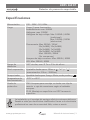
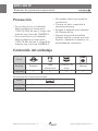
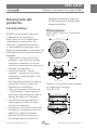
www.grupotemper.com
KDP1
360FP
Detector de presencia empotrable
Presence detector
KDP1 360 FP
Detector de presencia empotrable
Índice
Especificaciones
3
PRECAUCIÓN
4
Contenido del embalaje
4
Descripción del producto
5
Instalación y conexiones
6
Selección del lugar de instalación
6
Funciones adicionales y conexión
7
Instalación
9
Funcionamiento
14
Selectores Lux, Time
14
Función de aprendizaje
14
Modo de prueba
16
Resolución de problemas
Manual de instrucciones | 2
19
www.grupotemper.com
KDP1 360 FP
Detector de presencia empotrable
Especificaciones
Alimentación
220 - 240V~ 50 / 60Hz
Carga
Carga (↓) para iluminación:
Incandescente: max. 2000W
Halógena: max. 1000W
Halógena de bajo voltaje: Max. 1000VA / 600W
(tradicional)
Max. 1000VA / 900W
(electronica)
Fluorescente: Max. 900VA / 100uF
25x(1x18W); 12x(2x18W)
15x(1x36W); 7x(2x36W)
10x(1x58W); 5x(2x58W)
Max. 1000VA / 600W
(Sin compensar)
Lámpara de bajo consumo: Max. 600VA / 400W
LED: Max. 500VA / 400W
Rango de
detección
360º circular, max. Φ 7m a 2.5m de altura
Nivel crepuscular
Ajustable desde aprox. 10Lux a
“∞”y “ ”
(memorización: 10Lux - 2000Lux)
Temporizador
Ajustable desde aprox. 5secg a 30min, modo prueba y
Temperatura de
funcionamiento
-20ºC a +45ºC
Grado de
protección:
IP40. Lámpara para montaje en techo con clip de
resorte o caja de conexiones según el estándar
europeo.
IP 44. Montaje en superficie con KDP1 accesorio
superficie
La instalación y el montaje de equipos eléctricos siempre debe ser
llevada a cabo por electricistas cualificados. Llame a un electricista
profesional en caso de un eventual fallo, rotura o avería.
www.grupotemper.com
Manual de instrucciones | 3
KDP1 360 FP
Detector de presencia empotrable
Precaución
• Por protección, en el cableado
debe instalarse un interruptor
(250V CA,10A) de tipo C, carga I de
acuerdo con la norma EN60898-1
• Por protección, en el cableado
debe instalarse un interruptor
(250V CA,6A) de tipo C, carga II de
acuerdo con la norma EN60898-1
• No instalar sobre una superficie
conductora.
• Procure no abrir a menudo la
carcasa protectora.
• Apague el detector para cambiar
las fuentes de luz.
• Algunas marcas de bombillas
pueden estallar y causar picos de
tensión, dañando el detector sin
posibilidad de reparación.
Contenido del embalaje
Icono
Artículo
Detector
Tapa
protectora
Protector de
lente
Manual
Cantidad
1
1
2
1
Accesorios de compra opcionales
Icono
Artículo
Accesorio para montaje en superficie
Cantidad
1
Manual de instrucciones | 4
www.grupotemper.com
KDP1 360 FP
Detector de presencia empotrable
www.grupotemper.com
KDP1 360FP: Φ111.5 x 70mm (Ver
FIG.1-A)
Φ111.2
Φ 111.2
66.7
52.7
Φ 52
27
El KDP1 es un detector de techo
o superficie para interiores,
ideal para uso en instalaciones
industriales y comerciales. Sus
selectores regulables de tiempo
y luminosidad se ajustarán a sus
deseos y necesidades cumpliendo las
diferentes funciones de encendido y
apagado.
• Disponible en varios tipos de
montaje, a ras de techo o sobre
superficie, mediante un clip de
resorte o mediante el accesorio de
montaje en superficie.
• Ausencia total de “zonas
muertas” gracias a su zona de
cobertura circular de 360º y alta
sensibilidad.
• Alto rendimiento para un óptimo
control de todos los tipos de
sistemas de iluminación.
• Lleva incorporada la función de
“test de paso” para asegurar
que cubre correctamente todo el
campo de detección deseado.
• Dos orificios de entrada para
cables (lateral e inferior) para
facilitar la instalación.
• El protector de la lente le permite
minimizar o bloquear la zona de
detección según sus deseos.
• Sistema fotocelular de ahorro
de energía que le permite un
Dimensiones
FIG.1-A
Detector con accesorio de montaje
en superficie (opcional)
(Ver FIG.1-B)
Φ 111.2
35
Características
apagado automático según las
condiciones de luz ambientales
preseleccionadas.
57
Descripción del
producto
FIG.1-B
Manual de instrucciones | 5
KDP1 360 FP
Detector de presencia empotrable
Instalación y conexiones
Antes de instalar el detector desconecte la alimentación. Lea este manual de
instrucciones al completo antes de comenzar la instalación.
Selección del lugar de instalación
Se recomienda instalarlo a una altura de 2.5m. Su zona de detección puede
alcanzar los 7 metros de diámetro y 360º. (Ver FIG.2).
360
o
2. 5m
Φ4m
Φ7m
3.5m 2
2 3.5m
FIG.2
Preste atención a la dirección de paso cuando realice las pruebas.
El detector es más sensible al moviemiento transversal y menos al directo,
por lo que se reducirá la zona de cobertura. (Ver FIG.3).
Mayor sensibilidad al
movimiento a través del patrón
Menor sensibilidad al
movimiento hacia el detector
Φ6m
Φ4m
FIG.3
Manual de instrucciones | 6
www.grupotemper.com
KDP1 360 FP
Detector de presencia empotrable
Algunos consejos útiles para la
instalación
Funciones adicionales y
conexión
Debido a la sensibilidad del sensor
ante los cambios de temperatura,
evite las siguientes condiciones.
(Ver FIG.4)
•
Evite dirigir el detector hacia
objetos que pudieran moverse
con el viento como las cortinas,
plantas de cierta altura, árboles
pequeños, etc.
•
Evite dirigir el sensor hacia
zonas u objetos de superficie
muy reflectante como espejos,
monitores, etc.
•
No instale el detector cerca de
fuentes de calor tales como
respiraderos de calefacción,
de aire acondicionado,
calefacciones, luces, etc.
Botón de encendido manual
W
FIG.4-A
www.grupotemper.com
FIG.4-B
La carga puede ser encendida
manualmente pulsando el botón
externo que el detector lleva
incorporado (N.C. ≧ 10A, ver FIG.5FIG.6).
Cuando la carga está apagada,
puede conectarse pulsando el botón
de encendido manual. Una vez
conectada se apagará cuando no
se detecte movimiento o transcurra
el tiempo establecido por el
temporizador.
Valoración de la luz ambiente
De acuerdo con las variaciones del
nivel de luz ambiente, el detector
puede posponer el tiempo de
retardo de la carga en el encendido
y apagado y así evitar encendidos y
apagados innecesarios debidos a los
cambios de la misma:
Cambios en la luz ambiente de
claro a oscuro: si la luz ambiente se
mantiene por debajo de los valores
de luminosoidad establecidos
durante al menos 10 seg., la luz
se encenderá automáticamente
transcurrido ese tiempo. (el indicador
LED se encederá durante 10 seg.)
Cambios en la luz ambiente de
oscuro a claro: si la luz ambiente
excede durante al menos 5min el
Manual de instrucciones | 7
KDP1 360 FP
Detector de presencia empotrable
valor de Lux para el apagado, puede
haber varias reacciones de acuerdo
con los ajustes de tiempo realizados.
Temporizador ≧ 5min, la luz se
apagará automaticamente tras 5
minutos.
Temporizador < 5min, la luz se
apagará automáticamente si no
se detecta movimiento durante 5
minutos. Si se detecta movimiento
durante ese tiempo el temporizador
se reseteará de nuevo a 5 minutos.
Uso estándar (Ver FIG.5).
Alimentación
L
L
N N
Carga
Pulsador
N
L
FIG.5
Control de una carga mediante dos detectores para incrementar la zona de
cobertura (Ver FIG.6).
Alimentación
L
L
Alimentación
N N
Pulsador
L
Carga
L
N N
Pulsador
N
L
FIG.6
Manual de instrucciones | 8
www.grupotemper.com
KDP1 360 FP
Detector de presencia empotrable
Control de minutero de escalera (el temporizador debe estar ajustado en la
posición
Ver FIG.7).
Minutero de escalera
OUT IN
Alimentación
μ
L
L
N N
L
N
Carga
Pulsador
Pulsador
N
L
FIG.7
Instalación
Montaje en techo mediante clip de
resorte.
NOTA
Utilice siempre la tapa de protección
de las tomas cuando instale el
detector mediante el clip de resorte.
Para instalar el detector, realice un
orificio en la placa del techo con
un taladro de 65mm de diámetro
y asegúrese de dejar el cable de
alimentación fuera. Deje al menos
entre 6mm y 8mm de cable fuera
para realizar las conexiones. ( Ver
FIG.8).
Orificio de techo
Φ =65mm
Φ =65
6 - 8mm
30 - 35mm
FIG.8
www.grupotemper.com
Manual de instrucciones | 9
KDP1 360 FP
Detector de presencia empotrable
Consulte los diagramas de conexión
para realizarlas correctamente (fig.5
y FIG.7), después coloque la tapa y
ajústela con los tornillos. (Ver FIG.9)
Orificios punzonados pequeños para
cables de Φ8mm (Ver FIG.10-B);
Tornillos
anti-caida
Tapa protectora
Entrada de
cables
FIG.9
La tapa de protección de las tomas
está provista de orificios punzonados
para la entrada de cables.
Por favor, consulte el siguiente
dibujo para su realización.
Sin utilización de orificios
punzonados: cables de Φ2mm (Ver
FIG.10-A);
Sección del área para cables:
Φ2mm
FIG.10-A
Manual de instrucciones | 10
Sección del área para cables:
Φ8mm
FIG.10-B
Orificios punzonados grandes para
cables de Φ12,5mm (Ver FIG.10-B);
Sección del área para cables:
Φ12.5mm
FIG.10-C
www.grupotemper.com
KDP1 360 FP
Detector de presencia empotrable
Cierre hacia arriba los dos clips de
resorte del detector e introdúzcalo
dentro del agujero del techo. Debe
quedar firmemente sujeto. (Ver
FIG.11)
Φ=65
Tire de los cables de la caja estándar,
(FIG.13). Deje fuera de 6 a 8mm de
cable para realizar las conexiones.
(FIG.5 y FIG.7)
Cable de
alimentación
Clips
de resorte
FIG.11
Restablezca la alimentación.
Instalación en techo mediante caja
europea estándar de conexión
NOTA: no es necesario el uso de las
tapa protectora ni del clip de resorte.
6 - 8mm
FIG.13
Retire el marco decorativo del
detector tirando con fuerza en
sentido contrario a las ajugas del
reloj, después, coloque los dos
tornillos en los agujeros de la tapa
fije el detector a la caja estándar con
los tornillos. (Ver FIG.14).
Retire con una herramienta los clip
de resorte del detector. (Ver FIG.12)
FIG.14
FIG.12
www.grupotemper.com
Vuelva a colocar el marco y
restablezca la alimentación.
Manual de instrucciones | 11
KDP1 360 FP
Detector de presencia empotrable
Instalación mediante accesorio de
superficie KDP1
NOTA: no es necesario el uso de las
tapa protectora ni del clip de resorte.
El accesorio de montaje tiene 7 pares
de orificios punzonados de varios
tamaños que van desde los 41mm
a los 85mm para los diferentes
modos de instalación.(ver FIG.15A).
Seleccione las dos mismas figuras en
ambas tomas con su correspondiente
distancia de ajuste. (ver FIG.15B)
A
85
70
60
80
63
53
41
Orificios
punzonados
85
70
60
NO.
A
B
Dist.
A-B
1
41
41
41mm
2
53
53
53mm
3
60
60
60mm
4
63
63
63mm
5
70
70
70mm
6
80
80
80mm
7
85
85
85mm
FIG. 15B
Para que los cables conecten con la
fuente de alimentación a través del
accesorio de superficie, utilice los
alicates para romper los agujeros de
entrada laterales de la caja , luego
introduzca los cables y conéctelos..
Tire hasta tener de 6 a 8 mm para
realizar las conexiones. (ver FIG.16)
6 - 8mm
80
63
53
41
41
53
63
60
70
B
85
80
Orificios
punzonados
FIG.15-A
63
80
53
41
60
70
85
Cable entry
knock-out
FIG.16
Manual de instrucciones | 12
www.grupotemper.com
KDP1 360 FP
Detector de presencia empotrable
Elija los orificios punzonados
adecuados para fijar el accesorio de
superficie KDP1 a la superficie de la
placa del techo con dos tornillos con
arandela de goma. (FIG.17)
85
Arandela
de goma
80
70
63
60
53
41
41
53
63
80
60
70
85
Consulte los diagramas de cableado
para realizar las conexiones
correctamente. (Ver FIG.5-Ver FIG.7)
El símbolo ∆ del lateral del accesorio
de montaje en superficie, del cuerpo
del detector y del marco decorativo
indican la posición correcta de
montaje. Mantenga este símbolo
alineado en los tres elementos
para el montaje con los 4 tornillos
anti-caida, vuelva a poner el marco
decorativa y gírelo para ajustarlo.
(Ver FIG. 19)
FIG.17
Retire los dos clips de resorte del
detector (FIG. 12) y gire el marco
decorativo en sentido contrario a
las agujas del reloj, coloque los 4
tornillos de la tapa frontal en sus
correspondientes orificios.
Asegúrese de que los tornillos no
se sueltan ni resbalan para evitar
inconvenientes en instalaciones
posteriores. (Ver FIG.18)
FIG.19
Orificios
de fijación
FIG.18
www.grupotemper.com
Manual de instrucciones | 13
KDP1 360 FP
Detector de presencia empotrable
Funcionamiento
Selectores Lux, Time
Siga los valores marcados para ajustar los selectores Lux y Time de acuerdo
con sus deseos.
Selector
Función
Regulación del selector
Temporizador de
apagado de la
carga
Tiempo: ajustable desde 5 s. a 30 min.
Test: Test de paso
(2 s. encendido / 2 s. apagado)
: impulso corto para control de
minuteros de escalera
(1 s. encendido, 9 s. apagado)
Selección de
sensibilidad
luminosa
Rango: ajustable desde aprox. 10Lux
a
.
(aprendizaje): lectura del nivel de
luminosidad (10-2000Lux)
Función de aprendizaje
mediante selector
• Ajuste el selector a la posición
cuando la luz ambiente coincida
con el valor deseado
(Ver FIG.20-A).
• Si el selector ya está en la posición
, ajustelo en otra posición
durante más de 1 s. y vuelva a la
posición . (Ver FIG.20-B).
• La carga se apagará. La luz LED
parpadeará lentamente indicando
que se está entrando en el modo
de aprendizaje. El aprendizaje
estará completado en 25 s.
• Si la función se ha completado de
manera correcta el LED y la carga
permanecerán encendidos durante
Manual de instrucciones | 14
5 s. (Ver FIG.20-C).
• Tras este proceso el detector
volverá al modo AUTO con el LED y
la carga apagados.
NOTA
Si la luz ambiente deseada se
encuentra dentro del rango 102000Lux la luz LED parpadeará
rápidamente durante 5 s. Si se
encuentra por debajo el ajuste se
hará a 10Lux y si se encuentra por
encima el ajuste se hará a 2000Lux.
Durante el aprendizaje manténgase
lejos del detector para evitar
interferencias.
www.grupotemper.com
KDP1 360 FP
Detector de presencia empotrable
2000
10
300
100
2000
10
300
100
Ajuste a
desde
Ajuste a
otra posición
desde
2000
otra posición
10
300
100
2000
10
300
100
FIG.20-A
1 s. después vuelva
a la pos.
2000
W
10
300
100
FIG.20-B
Parpadeo lento - 25 s.
Carga apagada
W
W
LED y carga encendidos
durante 5 s.
(10 - 2000Lux)
Parpadeo rápido 5 s.
Carga apagada
(Nivel de luminosidad fuera
de rango)
W
LED y carga apagados
Detector ajustado en AUTO
FIG.20-C
www.grupotemper.com
Manual de instrucciones | 15
KDP1 360 FP
Detector de presencia empotrable
Modo de prueba
(no controlado por Lux)
Funciones de la luz LED
• La luz LED de indicación de
pruebas estña situada detrás de
la lente (Ver FIG.21). En el Test
de paso el LED se encenderá
durante 2 s. una vez se active el
detector. Si el detector se activa
continuamente se requerirán 2 s.
para que se encienda de nuevo.
• With the above said LED function,
the load is not necessary to be
connected while conducting walk
test.
• El LED actúa como indicador
únicamente durante el periodo de
auto-ajuste y en el Test de paso.
LED
FIG.21
Test de paso
La finalidad de esta prueba es
ajustar y chequear la cobertura de
detección. Ajuste el selector en la
posición “Test”y luego realice la
prueba. El control de luminosidad
estará desactivado durante esta
prueba.
NOTA
Tras conectarse a la alimentación
el detector tardará unos 60
segundos en auto-ajustarse, una vez
transcurrido este tiempo ya puede
realizar el test de paso.
FIG.22
Realización de la prueba
• La prueba debe realizarse dentro
de la zona de detección.
• Encienda el detector.
• Una vez encendido el detector
tarda unos 60 segundos en autoajustarse con la carga y el LED
encendidos, una vez ajustado se
apagarán.
• Camine desde el exterior a través
de la zona de cobertura hasta
que la luz LED se ilumine aprox.
durante 2 seg. (Ver FIG.22).
• Repita el paso anterior hasta que
la zona de cobertura esté ajustada
correctamente. Use la protección
de la lente durante la prueba.
Uso del protector de
lentes
El detector KDP1 viene provisto de 2
Manual de instrucciones | 16
www.grupotemper.com
KDP1 360 FP
Detector de presencia empotrable
protectores de lente para enmascarar
las zonas no deseadas dentro del
campo de detección. Cada lente
tiene dos capas, y cada capa incluye
6 pequeños segmentos, cada uno
de los cuales cubre un área de 30º
de detección. Por ejemplo, al instalar
un detector a una altura de 2.5m,
el área de detección puede llegar
a 1 m de diámetro si utilizamos el
protector de lente al completo; a más
de 4m de diámetro si usamos los
protectores de lente A+B y a más de
6m de diámetro si sólo utilizamos el
protector de lente A. (Ver FIG.23).
Una vez haya elegido el área de
detección, debe desechar los
protectores sobrantes. La zona
sombreada del protector de lente de
la FIG. 23 es la parte eliminada.
Ajuste de los protectores de lente:
El protector de lente se ajusta
encajando el surco circular del
mismo con el correspondiente
orificio circular de la parte trasera del
marco. (Ver FIG.24).
Utilización del protector total de la lente
A
B
C
Φ 1m
Utilización de las capas A y B del protector
Φ 4m
www.grupotemper.com
Manual de instrucciones | 17
KDP1 360 FP
Detector de presencia empotrable
Utilización de una de las capas
Φ6m
Utilización de parte del protector
30 o
Φ 1m
Φ 4m
Φ 6m
Φ 7m
FIG. 23
Manual de instrucciones | 18
www.grupotemper.com
KDP1 360 FP
Detector de presencia empotrable
FIG.24
Resolución de problemas
Problema
Posible causa
Solución sugerida
Los
dispositivos
de
iluminación
no se
encienden
1. No hay alimentación
2. Cableado incorrecto
3. El nivel de luz ambiente
es demasiado alto
4. La carga está estropeada
1. Conecte la alimentación
2. Consulte los esquemas
de instalación (FIG.5-FIG7) y
compruebe que las bombillas
e instalaciones funcionan
correctamente
3. Establezca el valor de
luminosidad por encima del
de la luz ambiente.
4. Cambie la carga
estropeada por una nueva
Los
dispositivos
de
iluminación
no se apagan
1. Ajuste de temporizador
incorrecto
2. Hay una posible
interferencia
3. Cableado incorrecto
1. Establezca el tiempo de
auto-apagado a un valor más
pequeño y cheque que la
carga se apaga de acuerdo a
este tiempo
2. Manténgase fuera de
la zona de cobertura del
detector cuando realice la
prueba
3. Compruebe que la carga y
los cables están conectados
correctamente
www.grupotemper.com
Manual de instrucciones | 19
KDP1 360 FP
Detector de presencia empotrable
Problema
Posible causa
Solución sugerida
La luz LED no
se enciende
1. El selector Time no está
en la posicion “Test”.
2. No hay alimentación
4. Cableado incorrecto
1. Gire el selector al modo
Test, el LED únicamente se
encenderá durante el autoajuste y el modo de prueba.
2. Conecte la alimentación
4. Consulte los diagramas de
conexión (FIG.5 - FIG.7)
Interferencias Puede que dentro de la
zona de cobertura haya
que activan
fuentes de calor, objetos
el detector
reflectantes u objetos que
puedan ser movidos por el
viento
Manual de instrucciones | 20
Evite colocar el detector
frente a fuentes de calor
como aire acondicionado,
ventiladores eléctricos,
estufas u objetos muy
reflectantes. Compruebe
que ningún objeto sensible
de ser movido por el viento
se encuentra en su zona de
detección
www.grupotemper.com
KDP1 360 FP
Detector de presencia empotrable
www.grupotemper.com
Manual de instrucciones | 21
KDP1 360 FP
Presence detector
Contents
Specification
23
CAUTION
24
Package contents
24
Product description
25
Installation and wiring
26
Select a proper location
26
Additional function and wiring
27
Installation procedure
29
Operation
34
Lux, Time knob
34
Lux learning function with knob
34
Test mode
36
Trouble shooting
Instructions manual | 22
39
www.grupotemper.com
KDP1 360 FP
Presence detector
Technical specifications
Rated voltage
220 - 240V~ 50 / 60Hz
Load
Load (↓) for Lighting:
Incandescent Lamp: max. 2000W
AC Halogen Lamp : max. 1000W
LV Halogen Lamp : Max. 1000VA / 600W (traditional)
Max. 1000VA / 900W (electronic)
Fluorescent Lamp : Max. 900VA / 100uF
25x(1x18W); 12x(2x18W)
15x(1x36W); 7x(2x36W)
10x(1x58W); 5x(2x58W)
Max. 1000VA / 600W
(Uncompensated)
Energy Saving Lamp: Max. 600VA / 400W
(include CFL & PL lamp)
LED Lamp : Max. 500VA / 400W
Detection Range
360º circular, max. Φ 7m at 2.5m height
Lux Adjustment
Adjustable from approx.10Lux to
(learning range:10Lux - 2000Lux)
Time Setting
Adjustable from approx. 5sec to 30min
and Test &
Operating
Temperature
-20ºC to +45ºC
Environmental
Protection
IP40 (Flush mount with spring clip or European
standard junction box)
IP44 (Surface mount with junction box KDP1)
“∞”and “ ”
Installation and assembly of electrical equipment must be carried
out by qualified electricians. Contact a qualified electrician in the
event of fault or break down.
www.grupotemper.com
Instructions manual | 23
KDP1 360 FP
Presence detector
CAUTION
•
•
•
A circuit breaker (250VAC, 10A)
type C according to EN60898-1
of loadⅠshall be installed in the
fixed wiring for protection.
A circuit breaker (250VAC, 6A)
type C according to EN60898-1
of loadⅡshall be installed in the
fixed wiring for protection.
•
•
•
Do not mount on conductive
surface.
Do not open the enclosure
frequently.
Turn off power when change the
light sources.
High in-rush current would be
caused when bulbs of certain
brands burned which might
damage the unit permanently.
Package contents
Pattern
Item
Quantity
Detector
Lens
shield
Protection
cap
1
Manual
1
2
1
Accessories for optional purchase
Rubber
washer
Pattern
Item
Non-dropping
screw Φ3 x 18mm
Wood screw
Φ 4 x 25.4mm
Quantity
4
2
Instructions manual | 24
Junction box
KDP1
1
www.grupotemper.com
KDP1 360 FP
Presence detector
Product description
Dimension:
Features
KDP1 360FP: Φ111.5 x 70mm (See
FIG.1-A)
www.grupotemper.com
Φ111.2
Φ 111.2
66.7
52.7
27
Φ 52
FIG.1-A
Detector with junction box KDP1
(Optional purchase)
(See FIG.1-B)
35
Φ 111.2
57
KDP1 is a ceiling flush mount and
surface mount both applicable
presence detector for indoor
application, which is ideal for use in
industrial and commercial
surroundings. With its knobs, the
time and Lux value can be adjusted
as user desired to match different
requirements for switching light on
and off.
• Available in various mounting
ways, e.g. surface mount or flush
mount with either spring clip or
with European standard junction
box by screws fitted.
• “No dead spot” zones in its
360º high intensity of detection.
• High performance for optimum
switching all types of lighting
sources.
• Built-in walk test function to
ensure the desired detection
field is covered entirely.
• Two cable entry holes either
from bottom or side entry are
available for easy and flexible
installation.
• Lens shield for minimizing or
blocking detecting field as user
desired.
• Energy saving with built-in
photocell allows for lighting
automatic ON & OFF according
to the pre-set ambient Lux level.
FIG.1-B
Instructions manual | 25
KDP1 360 FP
Presence detector
Installation and wiring
Please disconnect power completely and read the entire instruction manual
carefully before installation
Select a proper location
It is recommended to install at the height of 2.5m to gain the optimal
detection pattern. The detection range can reach up to 7m diameter, and
360º detection angle (See FIG.2).
360
o
2. 5m
Φ4m
Φ7m
3.5m 2
2 3.5m
FIG.2
Pay attention to the walking direction in the test proceeding.
It is more sensitive to movement across the detector and less senseitive
to movement directly towards to detector which will reduce the detection
coverage (See FIG.3).
More sensitive of movement
walking across the pattern
Less sensitive of movement
directly towards detector
FIG.3
Instructions manual | 26
www.grupotemper.com
KDP1 360 FP
Presence detector
Helpful tips for
installation
Since the detector is in response to
temperature change, please avoid
the following conditions (See FIG.4)
•
Avoid aiming the detector
toward the objects which may
be swayed in the wind, such as
curtain, tall plants, miniature
garden, etc.
•
Avoid aiming the detector
toward the objects whose
surface are highly reflective, such
as mirror, monitor, etc.
•
Avoid mounting the detector
near heat sources, such as
heating vents, air conditioning,
vents as dryers, lights, etc.
W
FIG.4-A
FIG.4-B
Additional Function and
Wiring
Manual on swithing with push
button switch
The load can be manually switched
on by using an external push
www.grupotemper.com
button switch (N.C. ≧ 10A type, See
FIG.5-FIG.6).
When the load is off, it can be
switched on by a short press ( ≤1sec)
on push button switch and Lux is
disabled. After the load is switched
on manually, the load can be
automatically switched off if no
movement is detected and the delay
time has expired.
Ambient light appraisal
According to the changeable
ambient light level, detector can
postpone load’s delay time
of turning on and off to avoid
unnecessarily turning on or off load
due to rapid ambient light change:
Ambient light level changes from
bright to dark: If the ambient light
level keeps be lower than the preset
Lux value for 10sec, the light will
be automatically switched on after
10sec. (LED will be on 10sec for
indication)
Ambient light level changes from
dark to bright: If the ambient light
level continuously exceeds the switch
off Lux value for 5min, there are
different reactions according to the
time setting value.
Time setting ≧ 5min, the light will be
automatically switched off after
5min.
Time setting < 5min, the light will be
automatically switched off when
the set time reached if no movement
Instructions manual | 27
KDP1 360 FP
Presence detector
is detected during the 5min. But if
there is movement detected within
the 5min, the time will be reset upon
detection and until 5min later, the
light is switched off.
KDP1 for standard application (See FIG.5).
Power box
L
L
N N
Load
Push button
(N.C. Type)
N
L
FIG.5
One load is controlled by two detectors to enlarge detection area (See FIG.6).
Power box
L
L
Power box
N N
Push button
(N.C. Type)
L
Load
L
N N
Push button
(N.C. Type)
N
L
FIG.6
Instructions manual | 28
www.grupotemper.com
KDP1 360 FP
Presence detector
Staircase timer switch control (timer should be set to
See FIG.7).
Staircase timer switch
OUT IN
Power box
μ
L
L
N N
L
N
Load
N
Push button Push button
(N.O. Type) (N.C. Type)
L
FIG.7
Installation procedure
Flush mount with spring clip
NOTE
When detector is flush mounted with
spring clip, protection cap of
terminals must be used.
To install detector, please drill a hole
with diameter of 65mm on ceiling
board and keep the power cable
outside. Please strip off 6 - 8mm
of cable sheathing for wiring ( See
FIG.8).
Drill a hole with
Φ =65mm on the
ceiling
Φ =65
6 - 8mm
30 - 35mm
FIG.8
www.grupotemper.com
Instructions manual | 29
KDP1 360 FP
Presence detector
Refer to wiring diagrams for correct
cables connection (FIG.5 - FIG.7),
then put protection cap back and
screw it tightly (See FIG.9).
Small knock-outs are used:Φ8mm
(See FIG.10-B);
Non-dropping
screw
Protection cap
Cables entry
FIG.9
Knock-outs on protection cap of
terminals are for cables entry.
Please refer to following illustration
for application.
No knock-outs are used:Φ2mm (See
FIG.10-A);
Section area for cable entry:
Φ2mm
FIG.10-A
Instructions manual | 30
Section area for cable entry:
Φ8mm
FIG.10-B
Big knock-outs are used:Φ8mm (See
FIG.10-C);
Section area for cable entry:
Φ12.5mm
FIG.10-C
www.grupotemper.com
KDP1 360 FP
Presence detector
Close up two spring clips of detector
and insert detector into the drilled
hole on ceiling tightly (See FIG.11).
standard junction box (See FIG.13),
then strip off 6 - 8mm of cable
sheathing for wiring (See FIG.5-FIG.7)
Φ=65
Power cable
Spring clips
6 - 8mm
FIG.11
Restore power supply.
Flush mount with European standard
junction box
NOTE: The protection cap of
terminals and spring clip are not
needed to be used when the
detector is flush mounted with
European standard junction box.
FIG.13
Turn the decorative frame of detector
anti-clockwise with proper strength,
then insert two screws into the
knock-outs on top cover and screw
the detector on European standard
junction box (See FIG.14).
Take off detector’s two spring clips
with tool before installation.
FIG.14
FIG.12
Pull out cables from European
www.grupotemper.com
Cover up the decorative frame and
restore power supply.
Instructions manual | 31
KDP1 360 FP
Presence detector
Surface mount with junction box
KDP1 (Optional purchase)
The distance
between A
and B
NO.
A
B
NOTE
The protection cap of terminals and
spring clip are not needed to be
used when the detector is surface
mounted.
1
41
41
41mm
2
53
53
53mm
3
60
60
60mm
4
5
63
70
63
70
63mm
70mm
There are 7 pairs of knock-outs with
various distances from 41mm to
85mm on the bottom cover of the
combined junction box KDP1 can
be selected for different mounting
applications (See FIG.15-A). To select
two same figures on both ends for
the corresponding distance for fixing
(See FIG.15-B).
6
80
80
80mm
7
85
85
85mm
A
85
70
60
FIG.15-B
To feed cables through the side of
junction box, please use the cutting
pliers to break the cable entry knockouts on the side of junction box, then
insert cables into junction box and
feed through it. Strip off 6 - 8mm
of cable sheathing for wiring (See
FIG.16).
80
53
41
63
6 - 8mm
Knock-outs
85
70
60
80
63
53
41
41
53
63
60
70
B
85
80
Knock-outs
63
80
FIG.15-A
53
41
60
70
85
Cable entry
knock-out
FIG.16
Instructions manual | 32
www.grupotemper.com
KDP1 360 FP
Presence detector
Choose proper knock-outs to fix the
junction box KDP1 on the surface of
ceiling board with two wood screws
attached with rubber washer (See
FIG.17).
Rubber
washer
85
80
70
63
60
53
41
41
53
63
80
60
70
85
FIG.17
Refer to wiring diagrams for correct
wire connection (See FIG.5 - FIG.7).
There is a “∆”symbol on the side of
the surface of junction box KDP1, the
housing of KDP1 and the decorative
frame respectively for position
verified convenience. Keep the ∆
symbol on the junction box KDP1
and detectors front cover in line to
assemble them with the attached 4
non-dropping screws, then cover up
the decorative frame of detector (See
FIG.19) and turn it to be tight.
Take off two spring clips of detector
(See FIG.12), turn the decorative
frame of detector anti-clockwise
with proper strength, then insert
the 4 non-dropping screws to the
corresponding screw holes on
detector’s front cover.
Afterwards, those 4 screws will not
drop off to provide conveniences
to the subsequent installations (See
FIG.18).
Fixing holes for
ceiling surface
mounting
Non-dropping
screw
FIG.19
Restore power supply.
FIG.18
www.grupotemper.com
Instructions manual | 33
KDP1 360 FP
Presence detector
Operation
Lux, Time knob
Follow the marked values to adjust Lux & Time knobs according to users
requirement.
2000
10
300
Set delay
off time for
load
Time: Adjustable from about 5sec
to 30min.
Test : Walk test operation (2sec on
/ 2sec off).
1s : Short impulse for staircase
timer switch control (1sec on,
9sec off).
Set the light
value for
switching on
load
Range
100
: Adjustable from approx.
10 Lux to “∞”.
( learn): The actual ambient
light level (10-2000Lux)
can be read in.
Lux learning function with
knob
Learning procedure:
• Adjust the knob to “ ” when
the ambient light level matches
with the desired value (See
FIG.20-A).
• When the knob is set to “ ”
originally, it should be adjusted
to other position more than 1
sec, then goes back to “ ”
(See FIG.20-B).
• Then the load is off. LED starts to
flash slowly indicating entering
into learning mode. Learning will
be completed within 25 seconds.
Afterwards, the LED and load will
keep on 5sec or LED flashes
Instructions manual | 34
2000
10
300
100
2000
10
300
100
Adjust knob to
“ ” from
other position
Adjust knob to
other position
from ” “
2000
10
300
100
2000
10
300
100
FIG.20-A
1sec after, goes
back to ” “
2000
10
300
100
FIG.20-B
www.grupotemper.com
KDP1 360 FP
Presence detector
•
quickly for 5sec and load is off to
confirm successful learning (See
FIG.20-C).
After learning procedure, the
detector returns to AUTO mode
with LED and load being off.
NOTE
When the actual light level is out of
the range 10 - 2000Lux, detector will
learn 25sec, then the red LED flashes
quickly for 5sec. When the actual
light level is below 10Lux, Lux value
is set to 10Lux, or is above 2000Lux,
Lux value is set to 2000Lux.
Installer should be away from the
detector to avoid affecting the
luminous flux that reaches the
detector when learning Lux value.
W
LED flashes slowly for 25sec
& Load is off
W
W
LED and load keep on 5sec
(the actual light level range
is 10 - 2000Lux)
LED flashes quickly for 5sec &
Load is off (the actual light
level range is out of 10 2000Lux)
W
LED and load off
Detector switches to AUTO
FIG.20-C
www.grupotemper.com
Instructions manual | 35
KDP1 360 FP
Presence detector
Test mode (Uncontrolled
by Lux)
LED function & reaction
• The red LED of KPD! is behind
the lens (See FIG.21) for test
mode indication. In walk test,
LED will turn on for 2sec once
the detector is triggered.
If detector is continuously
triggered, the red LED will
require an interval time of 2sec
to turn on again. With the above
said LED function, the load is not
necessary to be connected while
conducting walk test.
• LED functions as an indicator
only in warming up period and
test mode.
•
LED
FIG.21
Walk test
The purpose of conducting walk test
is to check and adjust detection
coverage. Set Time knob to “Test”,
then conducting a walk test. Lux
control is disabled in the walk test.
Instructions manual | 36
NOTE
It takes approx. 60sec for detector
to warm up after power is supplied
the first time or re-supplied after
shut off, then enters into normal
operation to carry out a walk test.
FIG.22
Test procedure
• Tester must be within the
detector coverage.
• Switch power on.
• Detector takes approx. 60sec to
warm up with load and LED on,
then turn off after warm up time.
• Walk from outside across to the
detection pattern until LED turns
on for approx. 2sec indicating
the movement has been
detected (See FIG.22).
• Repeat step 4.2.2.4 to conduct
walk test until the detection
pattern meets user’s demands.
Usage of lens shield
Usage of lens shield
KDP1 has provided 2 lens shields
for masking the undesired detection
area. Each lens shield has 2 layers,
each layer includes 6 small segments
www.grupotemper.com
KDP1 360 FP
Presence detector
and each segment can cover 30o
detection area. For example, to install
the detector at the height of 2.5m,
the detection range can reach up
to 1m diameter if the complete lens
shield has been used; and up to 4m
diameter if the A+B layers of lens
shield has been used; and up to 6m
diameter if only the A layer of lens
shield has been used (See FIG.23).
After user choosing the desired
detection area, the redundant lens
shield should be eliminated. The
shadow part of lens shield in FIG.23
refers to the cut-off part.
Fixing lens shield: There is circular
hook on the back of the decorative
frame and the lens shield is designed
with a circular groove. The lens shield
can be fitted by joining the groove
of lens shield with its corresponding
hook on the decorative frame (See
FIG.24).
The whole lens shield is used.
A
B
C
Φ1m
A & B layer of the lens shield is used.
Φ4m
www.grupotemper.com
Instructions manual | 37
KDP1 360 FP
Presence detector
A layer of the lens shield is used.
Φ6m
Utilización de parte del protector
30 o
Φ 1m
Φ 4m
Φ 6m
Φ 7m
FIG. 23
Instructions manual | 38
www.grupotemper.com
KDP1 360 FP
Presence detector
FIG.24
Trouble shooting
When KPD1 works abnormaly, please check assumptive problems
and suggested solutions in following table that will hopefully to solve
your problems.
Problem
Possible cause
Suggested solution
Lighting
device does
not turn on
1.Power does not turn on.
2.Wired incorrectly.
3.The ambient light level is
too high.
4.Malfunctioned load.
1.Switch on the power
2.Refer to wiring diagrams
(FIG.5-FIG.7) and check if the
load is malfunctioned.
3.Set Lux value to be above
the ambient light level then
trigger the detector and
check if the load is switched
on or not.
4.Replace the disabled
load with a new one.
Lighting
device does
not turn off
1. Incorrect time setting
2.Detector is nuisance
triggered.
3. Wired incorrectly.
1.Set auto off time to a
shorter time and check if the
load is switched off or not
according to the pre-set time
2.Keep away from detection
coverage to avoid activating
detector while doing the test.
3.Make sure load and wires
are connected correctly.
www.grupotemper.com
Instructions manual | 39
KDP1 360 FP
Presence detector
Problem
Possible cause
Suggested solution
LED does
not turn on
1.Time knob is not set to
“Test”.
2.No power supply.
3.Wired incorrectly.
1.Set Time knob to “Test”,
LED acts as an indicator only
in warming up time and test
mode.
2.Switch on the power.
3.Refer to wiring diagrams
(FIG.5-FIG.7).
Nuisance
triggering
There are heat sources,
highly reflective objects or
any objects which may be
swayed in the wind within
the detection coverage.
Avoid aiming the detector
toward any heat sources,
such as air conditioners,
electric fans, heaters or any
highly reflective surfaces.
Make sure there are no
swaying objects within the
detection coverage.
Instructions manual | 40
www.grupotemper.com
KDP1 360 FP
Presence detector
www.grupotemper.com
Instructions manual | 41
KDP1 360 FP
Presence detector
Instructions manual | 42
www.grupotemper.com
GARANTÍA • WARRANTY
GARANTIE • GARANTIA
2
años
years
années
anos
TEMPER ENERGY INTERNATIONAL S.L.
garantiza este aparato por 2 años ante
todo defecto de fabricación. Para hacer
válida esta garantía, es imprescindible
presentar con este resguardo el ticket o
factura de compra.
TEMPER ENERGY INTERNATIONAL
S.L. garantit cet apareil pour le durée
de 2 annèes contre tout défault de
fabrication. Pour le service de garantie,
vous devez présenter ce reçu avec du
ticket de caisse ou la facture.
TEMPER ENERGY INTERNATIONAL S.L.
guarantees this device during 2 years
against any manufacturing defect. For
warranty service, you must present this
receipt with the purchase receipt or
invoice.
TEMPER ENERGY INTERNATIONAL S.L.
garantía este aparelho contra defeitos
de fábrica ate 2 anos. Para o serviço
de garantia, você deve apresentar este
recibo com o recibo de compra ou
fatura.
Ref. Art.
Nº serie / Serial number
Nombre / Name / Nom / Nombre
Fecha de venta / Date of purchase
Date de vente / Data de venda
Sello establecimiento vendedor / Dealer stamp
Cachet du commercant / Cambo da firma
TEMPER ENERGY INTERNATIONAL S.L.
Polígono industrial de Granda, nave 18
33199 • Granda - Siero • Asturias
Teléfono: +34 902 201 292
Fax:
+34 902 201 303
Email:
[email protected]
Una empresa
del grupo