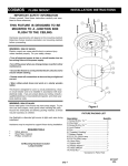
1
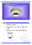
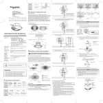
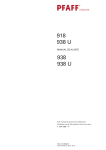
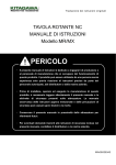
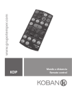
www.grupotemper.com
KDP3 360
Detector de presencia empotrable
Presence detector
KDP3 360
Detector de presencia empotrable
Índice
Especificaciones técnicas
3
Contenido del embalaje
4
Descripción del producto
4
Características
5
Dimensiones
5
Instalación y cableado
6
Selección del lugar de instalación
6
Funciones
7
Cableado
9
Instalación
Funcionamiento
10
14
Selectores Lux, Time
14
Uso del protector de lente
15
Test de paso
16
Resolución de problemas
17
Accesorio opcional
18
Manual de instrucciones | 2
www.grupotemper.com
KDP3 360
Detector de presencia empotrable
Especificaciones técnicas
Alimentación
230V~±10% 50 / 60Hz
Carga
Carga para iluminación:
Incandescente: máx. 2000W
Halógena : máx. 1000W
Halógena de bajo voltaje: máx. 1000VA / 600W
(tradicional)
Max. 1000VA / 900W (electrónica)
Fluorescente: máx. 900VA / 100uF
25x(1x18W); 12x(2x18W)
15x(1x36W); 7x(2x36W)
10x(1x58W); 5x(2x58W)
Max. 1000VA / 600W
(Sin compensar)
Lámpara de bajo consumo: máx. 600VA / 400W
(includas lámparas CFL y PL)
LED: máx. 500VA / 400W
Temporizador
Ajustable desde aprox. 10s a 30min, Test &
Rango de
detección
360º circular, max. Φ 8m a 2,5m de altura
Nivel crepuscular
Ajustable desde aprox. 10Lux a 2000Lux
Temperatura de
funcionamiento
0ºC a +45ºC (interior)
-20ºC a +45ºC (exterior)
Grado de
protección
Clase II
IP40 (Montaje empotrado con accesorio de empotrar
KDP3/5 y caja de mecanismos estándar)
IP54 (Montaje en superficie con accesorio de
superficie KDP3/5)
La instalación y el montaje de equipos eléctricos siempre debe ser
llevada a cabo por electricistas cualificados.
www.grupotemper.com
Manual de instrucciones | 3
KDP3 360
Detector de presencia empotrable
Precaución
Por protección, en el cableado de la carga I debe instalarse un interruptor
(250VCA,10A) de tipo C de acuerdo con la norma EN60898-1.
Por protección, en el cableado de la carga II debe instalarse un interruptor
(250VCA,6A) de tipo C de acuerdo con la norma EN60898-1.
No instalar sobre una superficie conductora.
Procure no abrir a menudo la carcasa protectora.
Apague el detector para cambiar las fuentes de luz.
Algunas marcas de bombillas pueden estallar y causar picos de tensión,
dañando el detector sin posibilidad de reparación.
Contenido del embalaje
Icono
Artículo
Detector
Tornillos Φ3
x 16mm
Protector de
lente
Manual
Cantidad
1
2
2
1
Accesorios de compra opcionales
Pattern
Item
KDP3/5
Accesorio de
superficie
Quantity
1
Descripción del producto
El KDP3 es un detector empotrable para el control automático de la
iluminación. Con el podrá seleccionar los valores deseados de iluminación y
tiempo de encendido con un bajo coste y ahorro de energía. Especialmente
diseñado para su uso en el hogar, almacenes, oficinas, salas de conferencia,
aulas, etc.
Manual de instrucciones | 4
www.grupotemper.com
KDP3 360
Detector de presencia empotrable
Características
•Disponible en varios tipos de montaje, superficie o empotrado, también
puede instalarse en una caja de conexiones estándar.
•Equipado con una luz LED roja para indicar su activación durante las
pruebas y el ajuste por infrarojos.
•Mando a distancia opcional.
•Posibilidad de ajuste de la luminosidad para el control de la iluminación
por infrarojos.
•Accesorios KDP3/5 para montaje en superficie o empotrable.
Dimensiones
KDP3: Φ110 x 55mm (Ver FIG.1-A)
Detector con KDP3/5 accesorio empotrar (opcional) (Ver FIG.1-B)
Φ110
55
40
52
FIG.1-A
110
40
85
62.5
FIG.1-B
www.grupotemper.com
Manual de instrucciones | 5
KDP3 360
Detector de presencia empotrable
Detector con KDP3/5 accesorio superficie (opcional)
(Ver FIG.1-C)
62
Φ110
Φ106
FIG.1-C
Instalación y cableado
Antes de instalar el detector desconecte la alimentación. Lea este manual de
instrucciones al completo antes de comenzar la instalación.
Selección del lugar de instalación
•El KDP3 puede ser instalado a una altura de entre 2 y 3m, se recomienda
hacerlo a 2,5m para obtener el máximo patrón de detección, el rángo de
detección puede alcanzar los 8m y un ángulo de 360º (Ver FIG.2).
360o
Vista lateral
2.5m
Vista superior
Φ8m
Φ4m
4m 2m
2m 4m
Mayor movimiento
Menor movimiento
FIG.2
•Preste atención a la dirección de paso cuando realice las pruebas.
El detector es más sensible al movimiento transversal y menos al directo,
por lo que se reducirá la zona de cobertura. (Ver FIG.3).
Manual de instrucciones | 6
www.grupotemper.com
KDP3 360
Detector de presencia empotrable
Mayor sensibilidad al
movimiento a través del patrón
Menor sensibilidad al
movimiento directo hacia
el detector
FIG.3
Algunos consejos útiles para la instalación
Debido a la sensibilidad del sensor ante los cambios de temperatura, evite las
siguientes condiciones. (Ver FIG.4)
• Evite dirigir el detector hacia objetos que pudieran moverse con el viento
como las cortinas, plantas de cierta altura, árboles pequeños, etc.
• Evite dirigir el sensor hacia zonas u objetos de superficie muy reflectante
como espejos, monitores, etc.
• No instale el detector cerca de fuentes de calor tales como respiraderos
de calefacción, de aire acondicionado, calefacciones, luces, etc.
Funciones
Apagado manual (ajustes de luminosidad desactivados):
Si la iluminación está activada, puede desactivarse manualmente.
Mantenga presionado el pulsador durante un segundo para activar el
apagado manual, la iluminación no se encenderá aunque se active el
detector.
Si la habitación está vacía durante un largo periodo (se supera el tiempo
de apagado), se desactivará el modo de apagado manual y el detector
recuperará el último ajuste realizado antes de entrar en el modo de pagado
manual.
Desde este modo, si presiona el pulsador de nuevo, se activará el modo de
encendido manual.
www.grupotemper.com
Manual de instrucciones | 7
KDP3 360
Detector de presencia empotrable
Encendido manual (ajustes de luminosidad desactivados):
Si la iluminación está desactivada, puede activarse manualmente.
En este modo la iluminación permanecerá encendida mientras el detector sea
activado y se apagará cuando no se detecte movimiento y haya transcurrido
el tiempo establecido mediante los ajustes.
Desde este modo, si presiona el pulsador de nuevo, se activará el modo de
apagado manual.
Función de retardo ON / OFF
De acuerdo con el nivel de luz ambiental, el detector puede retrasar el
tiempo de encendido y apagado de la iluminación para evitar encendidos y
apagados inncesarios debidos a cambios repentinos de la luz ambiente.
La luz ambiente cambia de clara a oscura:
Si la luz ambiente se mantiene por debajo del nivel de luminosidad
establecido dureante más de 10 segundos, la iluminación se activará
automáticamente. (La luz LED se encenderá durante 10 segundos)
La luz ambiente cambia de oscura a clara:
Si la luz ambiente excede continuamente el valor de luminosidad establecido
para el pagado durante 5 minutos el detector reaccionará de manera
diferente dependiendo del ajuste del temporizador.
•Ajuste ≥ 5min, la iluminación se apagará transcurridos los 5 minutos.
•Ajuste < 5min, la luz se apagará automáticamente cuando se alcance
el valor de tiempo establecido si no se detecta movimiento durante 5
minutos. Si se detecta movimiento durante los 5 minutos el valor del
tiempo volverá al estado inicial y después de 5 minutos la iluminación se
apagará.
Manual de instrucciones | 8
www.grupotemper.com
KDP3 360
Detector de presencia empotrable
Cableado
Funcionamiento normal (Ver FIG.8)
R/S R/S
KDP3 360
N N L L’
Pulsador
Carga
N
L
FIG.8
Minutero de escalera controlado por un detector
(Selector Time en la posición
, ver FIG.9)
Minutero
R/S R/S
KDP3 360
IN OUT
N N L L’
μ
Pulsador
N
Pulsador
L
Carga
N
L
FIG.9
www.grupotemper.com
Manual de instrucciones | 9
KDP3 360
Detector de presencia empotrable
Instalación
Montaje empotrado con caja de conexiones estándar
•Retire el marco decorativo del KDP3, separe la cabeza del detector de la
caja de potencia desatornillando los 4 tornillos (Ver FIG.11).
Caja de
potencia
Cabeza del
detector
Tornillo
anticaida
Marco
decorativo
FIG.11
•Pase los cables de alimentación por la caja de conexiones (Ver FIG.12),
luego pele 6 - 8mm de cable para realizar la conexión (Ver FIG.5 - FIG.10).
6 - 8mm
20 - 30mm
FIG.12
•Fije la caja de potencia a la caja de
conexiones mediante dos trornillos. (Ver
FIG.13).
60mm
FIG.13
Manual de instrucciones | 10
www.grupotemper.com
KDP3 360
Detector de presencia empotrable
•Vuelva a colocar la cabeza del detector y el marco decorativo (Ver FIG.11).
•Conecte la alimentación.
Montaje empotrado mediante KDP3/5 accesorio empotrar (opcional)
•Realice un orificio de 65mm de diametro en la placa del techo para sacar
los cables de alimentación. Pele 6 - 8mm de cable para realizar la conexión
(Ver FIG.14).
•Traspase la junta de goma del KDP3/5 con un destornillador y pase los
cables a través de ella (Ver FIG.15).
6 - 8mm
Φ=65
30 - 35mm
Perfore un orificio
de Φ=65mm en
el techo
FIG.14
•Consulte la FIG.5 - FIG.10 para realizar el cableado y atornille el KDP3/5
firmemente.
Tornillo
anticaida
Junta de
goma
Accesorio
KDP3/5
Entrada de
cables
FIG.15
www.grupotemper.com
Manual de instrucciones | 11
KDP3 360
Detector de presencia empotrable
•Cierre los clips de muelle del detector y coloquelo en el orificio realizado en
el techo. (Ver FIG.16).
•Conecte la alimentación.
Φ65mm
Alimentación
Clips de
sujección
FIG.16
Montaje en superficie mediante KDP3/5 accesorio superficie (opcional)
•El accesorio para montaje en superficie KDP3/5 dispone de 4 pares de
orificios punzonados con distintas distancias desde 41mm a 85mm en
su parte inferior según la necesidad del montaje a realizar (Ver FIG.17-A).
Seleccione los mismos orificios para realizar el montaje (Ver FIG.17-B).
Orificios
punzonados
A
85
85
70
60
70
60
B
41
41
41
60
70
85
Orificios
punzonados
41
60
70
85
FIG.17-A
NO.
A
B
Distancia A-B
1
41
41
41 mm
2
60
60
60 mm
3
70
70
70 mm
4
85
85
85 mm
FIG. 17-B
Manual de instrucciones | 12
www.grupotemper.com
KDP3 360
Detector de presencia empotrable
•Para pasar los cable de alimentación a través de los orificios utilice unos
alicates para romper los orificios punzonados del lateral del accesorio y
pase los cables a través de ellos. Pele 6 - 8mm de cable para realizar la
conexión (Ver FIG.18).
6 - 8mm
Orificios punzonados
de entrada de cables
30 - 35mm
FIG.18
•Seleccione los orificios apropiados para fijar el accesorio a la superficie del
techo mediante dos tornillos con arandela de goma (Ver FIG.19).
Toma de
tierra
70
60
41
41
Arandela
de goma
60
70
85
FIG.19
•Coloque cuatro tornillos anticaida en los orificios correspondientes de la
placa del detector (Ver FIG.20).
Tornillos
anticaida
Tornillos
anticaida
FIG.20
www.grupotemper.com
Manual de instrucciones | 13
KDP3 360
Detector de presencia empotrable
•Consulte los diagramas e conexión para una corecta instalación (Ver FIG.5
- FIG.10). Cuando coloque el palto de fijación del detector, encaje el orificio
rectangular del mismo con el resalte del accesorio (Ver FIG.21), luego fije la
cabeza del detector en la caja de potencia siguiendo la FIG.11 y fijándola
con los 4 tornillos anticaida.
41
60
70
85
Resalte
Tornillo
anticaida
Orificio
rectangular
FIG.21
•Cubra el detector con el marco decorativo y conecte la alimentación.
Funcionamiento
Selectores Lux, Time
Selector
Función
Ajuste
Selección de
sensibilidad
luminosa
Rango: desde 10 a 2000Lux.
Puede ser ajustado de acuerdo a las
necesidades de cada aplicación. Los
valores marcados son únicamente
como referencia.
Temporizador de
apagado de la
carga
Range: desde 10s a 30min
Test: Test de paso
(2 s. encendido / 2 s. apagado)
: impulso corto para control de
minuteros de escalera
(1 s. encendido, 9 s. apagado)
Manual de instrucciones | 14
www.grupotemper.com
KDP3 360
Detector de presencia empotrable
Uso del protector de lente
El detector KDP3 viene provisto de 2 protectores de lente para enmascarar
las zonas no deseadas dentro del campo de detección. Cada lente tiene dos
capas, y cada capa incluye 6 pequeños segmentos, cada uno de los cuales
cubre un área de 30º de detección.
Por ejemplo, al instalar un detector a una altura de 2,5m, el área de detección
puede llegar a 2 m de diámetro si utilizamos el protector de lente al
completo; y a más de 6m de diámetro si sólo utilizamos el protector de lente
A. (Ver FIG.22).
Utilización total del protector
Utilización parcial del protector
A
B
Φ 2m
Φ 2m
30°
Φ 6m
Φ 8m
Utilización de una capa
Utilización parcial del protector
30°
Φ 6m
Φ 6m
Φ 8m
FIG.22
La zona sombreada del protector de lente de la FIG.22 es la parte eliminada.
www.grupotemper.com
Manual de instrucciones | 15
KDP3 360
Detector de presencia empotrable
Ajuste de los protectores de lente: El protector de lente se ajusta encajando
el surco circular del mismo con el correspondiente orificio circular de la parte
trasera del marco decorativo. (Ver FIG.23-A & FIG.23-B).
Hendidura
circular
Resalte
circular
FIG.23-A
Marco decorativo
FIG.23-B
Test de paso (Ajuste de luminosidad deshabilitado)
La finalidad de esta prueba es ajustar y chequear la cobertura de detección.
Ajuste el selector en la posición “Test”y luego realice la prueba.
Nota
Tras conectarse a la alimentación el detector
tardará unos 60 segundos en auto-ajustarse,
una vez transcurrido este tiempo ya puede
realizar el test de paso.
FIG.24
Manual de instrucciones | 16
www.grupotemper.com
KDP3 360
Detector de presencia empotrable
Realización de la prueba
•La prueba debe realizarse dentro de la zona de detección.
• Encienda el detector.
• Una vez encendido el detector tarda unos 60 segundos en auto-ajustarse
con la carga y el LED encendidos, una vez ajustado se apagarán.
•Camine desde el exterior a través de la zona de cobertura hasta que la luz
LED se ilumine aprox. durante 2 seg. (Ver FIG.24).
•Ajuste el protector de lente para lograr la cobertura deseada.
Resolución de problemas
Problema
Posible causa
Solución sugerida
Los
dispositivos
de
iluminación
no se
encienden
1. No hay alimentación.
2. Cableado incorrecto.
3. Selector Lux ajustado
incorrectamente.
4. La carga está estropeada.
1. Conecte la alimentación.
2. Consulte los diagramas de
conexión.
3. Compruebe que el selector
Lux está en la posición
correcta.
4. Cambie la carga
estropeada por una nueva
Los
dispositivos
de
iluminación
no se apagan
1. Ajuste de temporizador
incorrecto
2. Hay una posible
interferencia
3. Cableado incorrecto
1. Establezca el tiempo de
auto-apagado a un valor más
pequeño y chequee que la
carga se apaga de acuerdo a
este tiempo
2. Manténgase fuera de
la zona de cobertura del
detector cuando realice la
prueba
3. Compruebe que la carga y
los cables están conectados
correctamente
La luz LED no
se enciende
1. El selector Time no está
en la posicion Test.
2. Se ha excedido el rango
de detección.
1. Gire el selector al modo
Test.
2. Camine dentro del área
efectiva de detección de 8m.
www.grupotemper.com
Manual de instrucciones | 17
KDP3 360
Detector de presencia empotrable
Problema
Posible causa
Interferencias Puede que dentro de la
zona de cobertura haya
que activan
fuentes de calor, objetos
el detector
reflectantes u objetos que
puedan ser movidos por el
viento
Solución sugerida
Evite colocar el detector
frente a fuentes de calor
como aire acondicionado,
ventiladores eléctricos,
estufas u objetos muy
reflectantes. Compruebe
que ningún objeto sensible
de ser movido por el viento
se encuentra en su zona de
detección
Accesorio opcional
Para ajustar el detector de manera fácil y segura se recomienda la compra del
mando a distancia por infrarrojos KDP, además este mando añade la función
de aprendizaje del nivel de luminosidad al detector.
Manual de instrucciones | 18
www.grupotemper.com
KDP3 360
Detector de presencia empotrable
www.grupotemper.com
Manual de instrucciones | 19
KDP3 360
Presence detector
Contents
Technical specifications
21
Package contents
22
Product description
22
Features
23
Dimension
23
Installation and wiring
24
Select a proper location
24
Function
25
Wiring
27
Installation procedure
28
Operation and function
32
Lux, Time knobs
32
Usage of lens shield
33
Walk test
34
Troubleshooting
35
Optional accessory
36
Instructions manual | 20
www.grupotemper.com
KDP3 360
Presence detector
Technical specifications
Rated voltage
230V~±10% 50 / 60Hz
Load
Load for Lighting:
Incandescent Lamp: max. 2000W
AC Halogen Lamp : max. 1000W
LV Halogen Lamp : Max. 1000VA / 600W (traditional)
Max. 1000VA / 900W (electronic)
Fluorescent Lamp : Max. 900VA / 100uF
25x(1x18W); 12x(2x18W)
15x(1x36W); 7x(2x36W)
10x(1x58W); 5x(2x58W)
Max. 1000VA / 600W
(Uncompensated)
Energy Saving Lamp: Max. 600VA / 400W
(include CFL & PL lamp)
LED Lamp : Max. 500VA / 400W
Auto Off Timer
Adjustment
Time (for lighting): Adjustable from approx. 10sec to
30min, Test &
Detection Range
360º circular, up to Φ 8m at 2.5m height
Lux Adjustment
Adjustable from approx. 10Lux to 2000Lux
Operating
Temperature
0oC to +45oC (Indoor usage)
-20oC to +45oC (Outdoor usage)
Environmental
Protection
Class II
IP40 (Flush mount with power box cap SP-96
and European standard junction box)
IP54 (Surface mount with junction box JB-41)
Installation and assembly of electrical equipment must be carried out
by qualified electricians. Contact a qualified electrician in the event of
fault or break down.
www.grupotemper.com
Instructions manual | 21
KDP3 360
Presence detector
Caution
A circuit breaker (250VAC, 10A) type C according to EN60898-1 of
loadⅠshall be installed in the fixed wiring for protection.
A circuit breaker (250VAC, 6A) type C according to EN60898-1 of loadⅡshall
be installed in the fixed wiring for protection.
Do not mount on conductive surface.
Do not open the enclosure frequently.
Turn off power when change the light sources.
High in-rush current would be caused when bulbs of certain brands burned
which might damage the unit permanently.
Package contents
Pattern
Item
Detector
Screw Φ3
x 16mm
Lens
shield
Manual
Quantity
1
2
2
1
Accessories for optional purchase
Pattern
Item
Junction box
KDP3/5
Quantity
1
Product description
KDP3 is a ceiling mount presence detector for lighting automation control.
User can pre-set the desired Lux and Time values by VR or IR setting for
automatic control lighting on/off with low initial cost and great energy saving
potential. It can be widely used in home, warehouse, open office, conference
room, class-room, library, corridor, etc.
Instructions manual | 22
www.grupotemper.com
KDP3 360
Presence detector
Features
•Available in various mounting methods, e.g. surface mount and flush
mount both applicable, and can be fitted into the European standard
junction box.
•A red LED is equipped as an indicator for test triggering and IR setting.
•IR remote controller for easy and quick settings (Optional purchase).
•The ambient Lux value can be read-in as the threshold for switching
on / off the loads by IR if the pre-set Lux value does not match user’s
requirement.
•The accessories KDP3/5 can be optionally purchased according to actual
mounting requirement.
Dimension
KDP3: Φ110 x 55mm (See FIG.1-A)
Detector with power box cap KDP3/5 surface accessory (Optional
purchase) (See FIG.1-B)
Φ110
55
40
52
FIG.1-A
110
40
85
62.5
FIG.1-B
www.grupotemper.com
Instructions manual | 23
KDP3 360
Presence detector
Detector with junction box KDP3/5 FP accessory (Optional purchase)
(See FIG.1-C)
62
Φ110
Φ106
FIG.1-C
Installation and wiring
Please disconnect power completely and read the entire instruction manual
carefully before installation
Select a proper location
•KDP3 can be installed at the height of 2 - 3m, it’s recommended to install
it at the height of 2.5m to gain the optimal detection pattern, the detection
range can reach up to the diameter of 8m and 360o detection angle
(See FIG.2).
360o
Side view
2.5m
Top view
Φ8m
Φ4m
4m 2m
2m 4m
Major Motion
Minor Motion
FIG.2
•Pay attention to the walking direction in the test proceeding. It is more
sensitive to movement across the detector and less sensitive to movement
directly toward to detector which will reduce the detection coverage (See
FIG.3).
Instructions manual | 24
www.grupotemper.com
KDP3 360
Presence detector
More sensitive of movement
walking across the pattern
Less sensitive of movement
directly towards detector
FIG.3
Helpful tips for installation
Since the detector is in response to temperature change, please avoid
the following conditions (See FIG.4)
• Avoid aiming the detector toward the objects which may be swayed in
the wind, such as curtain, tall plants, miniature garden, etc.
• Avoid aiming the detector toward the objects whose surface are highly
reflective, such as mirror, monitor, etc.
• Avoid mounting the detector near heat sources, such as heating vents, air
conditioning, vents as dryers, lights, etc.
Function
The function of R/S terminal
Terminal of R/S and push button (N.O.) can be series connected to control
load’s on / off manually. (case 1: on → off; case 2: off → on). While pressing
push button ( 1sec):
Case 1: Manual off switching (Lux settings is invalid):
If the lighting is under on mode, it can be manually switched off.
If the lighting is switched off manually by pressing ( 1sec) the push button
(activate the manual off mode), it keeps off even the detector is triggered.
If the room is vacant for a longer period (switch off delay time elapsed), the
manual off status (= manual off mode) is deactivated, then the detector
backs to the last setting mode before entering into manual off mode.
If the device is in the manual off mode, the second press on the push button
activates the manual on mode.
www.grupotemper.com
Instructions manual | 25
KDP3 360
Presence detector
Case 2: Manual on switching (Lux settings is invalid):
If the lighting is under off mode, it can be manually switched on.
If the lighting is switched on manually by pressing ( 1sec) the push button
(activate the manual on mode), it keeps on while the detector is triggered
constantly, and it turns off when no movement detected and the switch off
delay time elapsed, and the detector backs to the last setting mode before
entering into manual on mode.
If the device is in the manual on mode, the second press on the push button
activates the manual off mode.
Max. 10pcs slave detectors can be connected in parallel to the “R/S”
terminal of the master detector KDP3 to expand detection range if detection
range of one KDP3 does not match the user’s desire. Slave detector can
only be used to transfer detecting signal to master detector for expanding
the detection range, the connected loads will only act according to the preset values of master detector.
ON / OFF delay function
According to the changeable ambient light level, detector can postpone
load’s delay time of turning on and off to avoid load’s unnecessarily
turning on or off due to rapid ambient light change:
Ambient light level changes from bright to dark: If the ambient light
level keeps be lower than the preset Lux value for 10sec, the light will be
automatically switched on after 10sec. (LED will be on 10sec for indication)
Ambient light level changes from dark to bright: If the ambient light level
continuously exceeds the switch off Lux value for 5min, there are different
reactions according to the time setting value.
Time setting ≥ 5min, the light will be automatically switched off after 5min.
Time setting < 5min, the light will be automatically switched off when the
set time reached if no movement is detected during the 5min. But if there is
movement detected within the 5min, the time will be reset upon detection
and until 5min later, the light is switched off.
Instructions manual | 26
www.grupotemper.com
KDP3 360
Presence detector
Wiring
Normal operation (See FIG.8)
R/S R/S
KDP3 360
Push
button
(N.O.)
N N L L’
Load
N
L
FIG.8
Staircase timer switch controlled by one detector
(Time should be set to
, see FIG.9)
Staircase timer
R/S R/S
KDP3 360
IN OUT
N N L L’
μ
Push
button
(N.O.)
N
Push
button
(N.O.)
N
L
Load
L
FIG.9
www.grupotemper.com
Instructions manual | 27
KDP3 360
Presence detector
Installation procedure
Flush mount with European standard junction box
•Take off decorative frame of KDP3, then take the detector head apart from
power box by unscrew its 4pcs non-dropping screws (See FIG.11).
Power box
Detector head
Non-dropping
screw
Decorative
frame
FIG.11
•Pull out AC power cables from European standard junction box (See
FIG.12), then strip off 6 - 8mm of cable sheathing for wiring (See FIG.5 FIG.10).
6 - 8mm
20 - 30mm
FIG.12
•Fix the power box into European standard
junction box with 2pcs screws (See FIG.13).
60mm
FIG.13
Instructions manual | 28
www.grupotemper.com
KDP3 360
Presence detector
•Fix the detector head on power box by inserting its four non-dropping
screws into the corresponding screw holes, then cover up the decorative
frame (See FIG.11).
•Restore the power supply.
Flush mount with power box cap KDP3/5 (Optional purchase)
•To install detector, please drill a hole with diameter of 65mm on ceiling
board and keep the power cable outside. Please strip off 6 - 8mm of cable
sheathing for wiring (See FIG.14).
6 - 8mm
Φ=65
30 - 35mm
Drill a hole with
Φ=65mm on the
ceiling
FIG.14
•Use screwdriver to break the rubber gasket on KDP3/5, then feed cables
through it (See FIG.15).
•Please refer to illustration of FIG.5 - FIG.10 for correct wiring and then
screw the KDP3/5 tightly.
Non-dropping
screw
Rubber gasket
Power box cap
KDP3/5
Cable entry
FIG.15
www.grupotemper.com
Instructions manual | 29
KDP3 360
Presence detector
•Close up detector’s two spring clips and insert detector into the drilled
hole on ceiling (See FIG.16).
•Restore the power supply.
Φ65mm
Power cable
Spring clips
FIG.16
Surface mount with junction box KDP3/5 (Optional purchase)
•There are 4 pairs of knockouts with various distances from 41mm to 85mm
on the bottom cover of combined junction box JB-41 can be selected for
different mounting applications (See FIG.17-A). Select two same figures on
both ends for the corresponding distance for fixing (See FIG.17-B).
Knockouts
A
85
85
70
60
70
60
B
41
41
41
60
70
85
41
60
70
85
Konckouts
FIG.17-A
NO.
A
B
The distance
between A and B
1
41
41
41 mm
2
60
60
60 mm
3
70
70
70 mm
4
85
85
85 mm
FIG. 17-B
Instructions manual | 30
www.grupotemper.com
KDP3 360
Presence detector
•To feed AC power cables through the side of junction box, please use the
cutting pliers to break the cable entry knockouts on the side of junction
box, then insert cables into junction box and feed through it. Strip off 6 8mm of cable sheathing for wiring (See FIG.18).
6 - 8mm
Cable entry
knockout
30 - 35mm
FIG.18
•Choose proper knockouts to fix the junction box JB-41 on the surface of
ceiling board with 2pcs wood screws attached with rubber washer
(See FIG.19).
Earth
terminal
70
60
41
41
Rubber
washer
60
70
85
FIG.19
•Insert 4pcs non-dropping screws to the corresponding screw holes on
detector’s fixing plate, and those 4pcs screws will not drop off to provide
convenience to the subsequent installations (See FIG.20).
Tornillos
anticaida
Tornillos
anticaida
FIG.20
www.grupotemper.com
Instructions manual | 31
KDP3 360
Presence detector
•Refer to wiring diagrams for correct wiring connection (See FIG.5 - FIG.10).
There is a square hole in the fixing plate, when you put the fixing plate into
the junction box, please fit the fillister to the junction box’s protrusion
(See FIG.21), then fix the detector head on the power box following FIG.11
and assemble them with the attached 4pcs nondropping screws.
41
60
70
85
Protrusion
Non-dropping
screw
Square
hole
FIG.21
•Cover up the detector’s decorative frame and restore the power supply.
Operation and function
Lux, Time knobs
Knob
Function
Knob setting
Set the light value
for switching on
load
Range: Approx. 10 to 2000Lux
User can set the knob according to
their requirement for application. The
marked values are for reference only.
Set delay off time
for lighting
Range: Approx. 10sec to 30min
Test : Test mode (Load and red LED
will be 2sec on, 2sec off)
: Short impulse mode for staircase
timer switch control (Load will be 1sec
on, 9sec off)
Instructions manual | 32
www.grupotemper.com
KDP3 360
Presence detector
Usage of lens shield
KDP3 has provided 2 lens shields for masking the undesired detection area.
Each lens shield has 2 layers, each layer includes 6 small pieces of shield and
each small piece of shield can cover 30o detection area.
For example, to install the detector at the height of 2.5m, the detection range
can reach up to 2m diameter if the complete lens shields have been used,
and up to 6m diameter if only the A layer of lens shield has been used
(See FIG.22).
The whole lens shield is used.
Part of the lens shield is used.
A
B
Φ 2m
Φ 2m
30°
Φ 6m
Φ 8m
A layer of the lens shield is used.
Part of the lens shield is used.
30°
Φ 6m
Φ 6m
Φ 8m
FIG.22
The shadow part of the lens shields in the FIG.22 is needed to be
cut off.
www.grupotemper.com
Instructions manual | 33
KDP3 360
Presence detector
Fixing lens shield: There is circular hook on the back of the decorative frame
and the lens shield is designed with a circular groove. The lens shield can be
fitted by joining the groove of lens shield with its corresponding hook on the
decorative frame (See FIG.23-A & FIG.23-B).
Circular
groove
Circular
hook
FIG.23-A
Decorative frame
FIG.23-B
Walk test (Lux setting is invalid)
The purpose of conducting the walk test is to check and adjust the detection
coverage. Set Time / Time1 knob to “Test”, then conducting a walk test.
Note
It takes approx. 60sec for detector to warm
up after power is supplied, then enters into
normal operation to carry out a walk test.
FIG.24
Instructions manual | 34
www.grupotemper.com
KDP3 360
Presence detector
Test procedure
•Tester must be within the detection coverage.
•Switch power on.
•KDP3 takes approx. 60sec to warm up with load and red LED on, then turns
off after warming up time.
•Walk from outside across to the detection pattern until red LED turns on for
approx. 2sec then off, the next trigger should be 2sec interval (See FIG.24).
•Adjusting lens shield for desired detection range.
Trouble shooting
Problem
Possible cause
Suggested solution
Lighting
device does
not turn on
1.Power does not turn on.
2.Wired incorrectly.
3.Lux knob adjusted
incorrectly.
4.Malfunctioned load.
1. Switch on the power.
2. Refer to wiring diagrams
for correct connection.
3. Check if Lux knob is set to
the correct position.
4. Replace the disabled load
with a new one.
Lighting
device does
not turn off
1. Auto off time is set too
long.
2. Detector is nuisance
triggered.
3. Wired incorrectly.
1. Set auto off time to a
shorter time and check the
load is switched off or not
according to the pre-set off
time.
2. Keep away from detection
coverage to avoid activating
detector while doing the test.
3. Make sure load and wires
are connected correctly.
LED does not
turn on
1. Time konb is not set to
Test.
2. Exceeding the detection
range.
1. Time knob must be located
to Test position.
2. Walk in the effective
detection range of 8m
diameter.
www.grupotemper.com
Instructions manual | 35
KDP3 360
Presence detector
Problem
Possible cause
Suggested solution
Nuisance
triggering
There are heat sources,
highly reflective objects or
any objects which may be
swayed in the wind within
the detection coverage.
Avoid aiming the detector
toward any heat sources,
such as air conditioners,
electric fans, heaters or any
highly reflective surfaces.
Make sure there are no
swaying objects within the
detection coverage.
Optional accessory
It is strongly recommended to purchase our high quality IR remote controller
KDP for easy and safe setting operations on KDP3, and to own the “Lux
learning” function to read-in the actual light level as threshold for switching
the connected load.
Instructions manual | 36
www.grupotemper.com
KDP3 360
Presence detector
www.grupotemper.com
Instructions manual | 37
KDP3 360
Presence detector
Instructions manual | 38
www.grupotemper.com
GARANTÍA • WARRANTY
GARANTIE • GARANTIA
2
años
years
années
anos
TEMPER ENERGY INTERNATIONAL S.L.
garantiza este aparato por 2 años ante
todo defecto de fabricación. Para hacer
válida esta garantía, es imprescindible
presentar con este resguardo el ticket o
factura de compra.
TEMPER ENERGY INTERNATIONAL
S.L. garantit cet apareil pour le durée
de 2 annèes contre tout défault de
fabrication. Pour le service de garantie,
vous devez présenter ce reçu avec du
ticket de caisse ou la facture.
TEMPER ENERGY INTERNATIONAL S.L.
guarantees this device during 2 years
against any manufacturing defect. For
warranty service, you must present this
receipt with the purchase receipt or
invoice.
TEMPER ENERGY INTERNATIONAL S.L.
garantía este aparelho contra defeitos
de fábrica ate 2 anos. Para o serviço
de garantia, você deve apresentar este
recibo com o recibo de compra ou
fatura.
Ref. Art.
Nº serie / Serial number
Nombre / Name / Nom / Nombre
Fecha de venta / Date of purchase
Date de vente / Data de venda
Sello establecimiento vendedor / Dealer stamp
Cachet du commercant / Cambo da firma
TEMPER ENERGY INTERNATIONAL S.L.
Polígono industrial de Granda, nave 18
33199 • Granda - Siero • Asturias
Teléfono: (+34) 902 201 292
Fax:
(+34) 902 201 303
Email:
[email protected]
Una empresa
del grupo