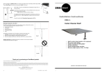
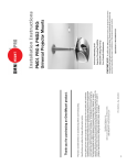
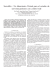
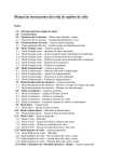
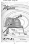
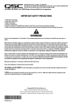
1
OBLED80FM
FULL MOTION MOUNT FOR LED TVS
OBLED80FM = L2-OM1100407-CON-062811vC
Instruction Manual / Manual de instrucciones
VERSION C
Reduce.Reuse.Recycle
ON WALL
SOBRE LA PARED
IN WALL
DENTRO DE LA PARED
HAVE A SMARTPHONE?/ ¿TIENES UN TELEFONO INTELIGENTE?
Max screen size: 60”
Max weight 80 lbs – 36.3 KG
CAUTION: DO NOT EXCEED MAXIMUM
LISTED WEIGHT CAPACITY. SERIOUS
INJURY OR PROPERTY DAMAGE MAY
OCCUR!
Scan this QR code with your Smartphone to see
a short installation video. This installation video
is for demonstration purposes only. Please refer
to this manual for complete instructions.
Escanear este codigo QR con su teléfono inteligente para
ver un corto video de instalación. Este video de instalación
es con proposito de demostracion. Consulte el manual
para completar las instrucciones.
ISSUES/QUESTIONS? / ¿PREGUNTAS?
STOP
PARADA
PARADA
Before you return this product to Sam’s Club,
please let us help you. You can reach us by
phone 24/7 at 877.PLUGD.IN (877.758.4346).
Antes de devolver este producto al Sam’s Club, por
favor, déjenos ayudarle. Usted puede contactarnos por
teléfono 24/7 llame al 877.PLUGD.IN (877.758.4346).
WARNING!
SEVERE PERSONAL INJURY AND PROPERTY DAMAGE CAN RESULT FROM IMPROPER
INSTALLATION OR ASSEMBLY. READ THE FOLLOWING WARNINGS BEFORE BEGINNING.
If you do not understand the instructions or have any concerns or questions, please contact us 24/7 at
877.PLUGD.IN (877.758.4346).
Do not install or assemble if the product or hardware is damaged or missing. If you require replacement parts
please call 877.PLUGD.IN (877.758.4346).
FOR WALL MOUNTED PRODUCT: This product has been designed for use on a vertical wall constructed of
wood studs or solid concrete. Wood studs being defined as a wall consisting of a minimum of 2” x 4” studs
with a maximum of 24” stud spacing and a minimum of 16” stud spacing with a maximum of ½” inch of wall
covering (drywall, lath, plaster). For safe installation, the wall you are mounting to must support 4 times the
weight of the total load (flat panel and wall mount). If not, the surface must be reinforced to meet this
standard. The installer is responsible for verifying that the wall structure/surface and the anchors used in the
installation will safely support the total load. Do not use this product for any application other than those
specified by OmniMount.
This product may contain moving parts. Use with caution.
DO NOT EXCEED THE MAXIMUM WEIGHT CAPACITY FOR THIS PRODUCT.
¡ADVERTENCIA!
LA INSTALACIÓN O EL MONTAJE INAPROPIADOS PUEDEN PROVOCAR LESIONES,
DAÑOS MATERIALES O INCLUSO LA MUERTE. ANTES DE COMENZAR, LEA LAS
SIGUIENTES ADVERTENCIAS.
Si las instrucciones no le resultan claras o si tiene alguna duda o pregunta, comuníquese con un instalador
calificado. Si el producto o el hardware está dañado o no se le envió alguna pieza, no realice la instalación ni
el montaje. Si necesita piezas de repuesto, comuníquese con el servicio de Atención al cliente llame al
877.PLUGD.IN (877.758.4346).
PARA MONTAJE EN LA PARED: Este producto está diseñado para ser instalado en paredes verticales con paneles
de madera u hormigón. Se define a los paneles verticales como una pared que consiste de un mínimo de paneles de
5 x 10 cm con un espacio entre paneles máximo de 60 cm y un espacio mínimo entre paneles de 41 cm, con un
máximo de cobertura de pared (hoja de yeso, listón, yeso) de 13 mm. Para realizar una instalación segura, la pared
elegida debe ser capaz de soportar 4 veces el peso de la carga total (montaje plano del panel y de la pared). De lo
contrario, deberá reforzar la superficie para que cumpla con este requisito. El instalador es el responsable de
comprobar que la estructura/superficie de la pared y los tacos que se utilizan en la instalación soporten la carga total
de manera segura.
Este producto puede contener componentes móviles. Úselo con precaución.
NO EXCEDA LA CAPACIDAD DE PESO MÁXIMA PARA ESTE PRODUCTO.
MAXIMUM WEIGHT CAPACITY
MÁXIMA CAPACIDAD DE PESO
POUNDS (LBS) / KILOGRAMS (KG)
LIBRAS (LB) / KILOGRAMOS (KG)
MAXIMUM SCREEN SIZE
TAMAÑO DE PANTALLA MÁXIMO
COMPLETE UNIT
80 (LBS) / 36.3 (KG)
60 in. (152.4 cm)
60”
USE WITH FLAT PANELS LARGER THAN THE MAXIMUM
WEIGHT AND/OR SCREEN SIZE MAY RESULT IN
INSTABILITY CAUSING POSSIBLE INJURY.
EL USO DE LA MONTURA CON TELEVISORES MÁS GRANDES
QUE EL PESO O EL TAMAÑO MAXIMO PUEDEN PROVOCAR LA
FALLA DE LA MONTURA Y PROVOCAR LESIONES.
80 lbs
36.3 kg
P2
MOUNTING CONFIGURATION APPENDIX
APÉNDICE DE LA CONFIGURACIÓN DEL MONTAJE
200mm (7-7/8”)
100mm (3-15/16”)
100mm (3-15/16”)
1
200mm (7-7/8”)
CONFIGURACIÓN
100mm (3-15/16”)
CONFIGURATION
200mm (7-7/8”)
2
400mm (15-3/4”)
CONFIGURACIÓN
300mm (11-13/16”)
CONFIGURATION
600mm (23-5/8”)
CONFIGURATION
CONFIGURACIÓN
3
400mm (15-3/4”)
300mm (11-13/16”)
400mm (15-3/4”)
400mm (15-3/4”)
300mm (11-13/16”)
400mm (15-3/4”)
300mm (11-13/16”)
CONFIGURACIÓN
4
200mm (7-7/8”)
CONFIGURATION
P3
CONTENTS / CONTENIDO
SCREW / HARDWARE PACK FOR TV / TORNILLOS / KIT PARA LA TV
Monitor Kit L-U-vD
M-A
X4
M-B
X4
M-C
X4
M-D
M-E
X4
M-F
X4
X4
M-G
X4
Spacers
Spacers
M-I
M-J
X4
X4
M-H
Washers
Washers
X4
M-K
M-L
SCREWS/HARDWARE PACK FOR WALL
Screws / Hardware for Flat Panel (Monitor Kit L-U-vD)
Wall Kit 516-4vC
W-A
W-B
Part #
Qty
Description
M-A
4
Philips screws M4 x 15mm
M-B
4
Philips screws M4 x 30mm
M-C
4
Philips screws M5 x 15mm
M-D
4
Philips screws M5 x 30mm
M-E
4
Philips screws M6 x 15mm
M-F
4
Philips screws M6 x 30mm
M-G
4
Philips screws M8 x 15mm
M-H
4
Philips screws M8 x 30mm
M-I
4
Round Spacers: M6-M8 x 5mm
M-J
4
Round Spacers: M6-M8 x 10mm
M-K
4
Round Washers: M4-M5
M-L
4
Round Washers: M6-M8
Screws / Hardware for Wall Mounting (Wall Kit 516-4vC)
W-C
Description
Part #
Qty
X4 / HARDWARE PACK
X4
X4
SCREW
FOR PRODUCT
W-A
4
Lag Bolts (8mm x 65mm)
OM1100407vA
W-B
4
Steel Washer (18mm x 8.5mm x 1.5mm)
W-C
4
Wall Anchor (10mm OD x 8mm ID)
Screws / Hardware for Product (OM1100407vA)
P-A
P-B
P-C
P-D
X8
X8
X4
X2
P-E
P-F
P-G
X4
X2
X1
Description
Part #
Qty
P-A
8
M6 Carriage Bolt
P-B
8
M6 Nylon Lock Nut
P-C
4
M6 Washers
P-D
2
M5 Phillips Screw
P-E
4
M5 Button Head Screw
P-F
2
3mm Allen Wrench
P-G
1
Wrench
P4
CONTENTS / CONTENIDO
5
2
1
9
4
3
6
11
8
7
10
15
CONTENT
Part #
Qty
Description
1
1
Wall Plate / Arm Assembly
2
1
Rear Cable Management Cover
3
2
End Plate
4
4
M5 Button Head Screws
5
2
Top & Bottom Plate
6
1
Arm Cable Management Cover
7
1
Flat Panel Plate
8
4
Extension Adapter
9
8
Tilt Tension Screw
10
1
Wall Trim
11
1
Trim Spacer (Not needed for IN WALL installation)
12
1
Double Wood Stud / Solid Concrete Wall Template (On Wall)
13
1
Double Wood Stud Wall Template (In Wall)
14
1
Single Wood Stud Wall Template
15
1
Stud Finder / Level
P5
CAUTION
BEFORE CUTTING HOLES IN DRYWALL:
Your wall may be acting as a fire break, cutting holes in it can compromise the effectiveness of this barrier. Before
cutting a hole in your fire break, please consult with your local building regulatory authority, or a qualified installation
expert for building codes and regulations regarding this form of installation.
RUNNING CABLES AND CORDS IN WALL:
High voltage cables and other utilities might be routed behind your fire break so use caution before cutting. In the event
you come across high voltage cables, or do not know how to locate these cables, stop and contact your local building
regulatory authority, or a qualified electrician for building codes and regulations regarding this type of installation. Per
NEC Article 400.8 routing power cables through or between walls is prohibited. For a complete list of low voltage signal
cables that can be routed into or through your wall, please refer to NEC Article 725/CEC Section 16.
INSTALACION DE CABLES DENTRO DE LA PARED:
Cables de alto voltaje u otros servicios podrían estar instalados detras de la pared. Por lo tanto, debe de ser cuidadoso al momento de cortar la
pared. Si durante la operación encontráse cables de alta tensión ó si tuviese dudas de como localizar éstos cables entonces contácte a la
autoridad local de construcción o a un electricista calificado para obtener los códigos de instalación y las normas de instalación para este tipo de
instalación. Según el artículo NEC 400.8 guíar cables de energía a través de la pared es prohibido. Para una lista completa de cables de bajo
voltaje que pueden ser guíados dentro de la pared revise el Artículo NEC 725/CEC Sección 16.
ANTES DE CORTAR LA PARED DE DRYWALL (YESO):
Su pared actúa como un protector contra el fuego, el corte de la pared podría comprometer la efectividad de protección. Antes de cortar la pared
consulte con la autoridad local de construcción o con un instalador certificado acerca de los códigos de construcción y regulaciones.
IMPORTANT! / ¡IMPOTARNTE!
Please be sure you have followed all steps on the
installation template before proceeding further with
this instruction manual. If you have completed the
installation template correctly, you should have
holes drilled into either wood studs, or solid
concrete.
Asegurece que usted haya seguido todos los pasos de la
plantilla de instalación antes de proseguir con este manual de
instrucción. Si usted ha seguido los pasos la plantilla de
instalación correctamente, usted debera de tener agujeros
perforados en la viga de madera, o concreto sólido.
14
12
12
14
13
13
STEP 7: Match mounting configuration with mounting holes on back of flat panel using flat panel plate (Part #7)
and extension adapters (Part #8). IMPORTANT! Flat panel plate (Part #7) must be centered between mounting
holes.
PASO 7: Ulitizando la laca de la television (Parte #7) ubique los agujeros detras de la television. Si los agujeros tienen una ubicacion
mayor a los 200mm x 200mm entonces debera de utilizar las extensiones (Parte #8). IMPORTANTE! La placa de la television (Parte #7)
debera de estar centrada respecto a los agujeros del televisor.
CONFIGURATION 1
CONFIGURATION
CONFIGURACIÓN
1
Please see pages 8-9.
This install may need:
• Vertical adjust
LA CONFIGURACIÓN 1
Por favor revise las paginas 8-9.
esta instalacion podria necesitar:
• Ajuste vertical
CONFIGURATION 2-4
CONFIGURATION
CONFIGURACIÓN
CONFIGURATION
CONFIGURACIÓN
2
Please see page 10-11
CONFIGURACIÓN 2-4
Por favor revise las paginas 10-11.
3
CONFIGURATION
CONFIGURACIÓN
4
NOTE: FOR VESA MOUNTING CONFIGURATION DIMENSIONS, SEE APPENDIX ON PAGE 3.
NOTA: PARA LAS DIMENSIONES DE CONFIGURACION VESA, VEA EL APÉNDICE EN LA PÁGINA 3.
P7
ATTENTION: IF YOUR AV ACCESS IS OBSTRUCTED
ATENCIÓN: SI EL ACCESO DE CABLEADO QUEDA OBSTRUIDO
If your AV access is obstructed the flat panel plate (Part #7) is designed for vertical adjustment with 100mm x
100mm hole patterns.
Si la placa plana obstruye el acceso de cableado la (Parte #7) permite el ajuste vertical con patrones del agujero del 100mm x 100mm.
7
ATTENTION: IF YOUR AV ACCESS IS STILL OBSTRUCTED, WE OFFER AN ADAPTER (VPAFM100).
PLEASE CONTACT CUSTOMER SERVICE AT 877.PLUGD.IN (877.758.4346) FOR DETAILS.
ATENCIÓN: SI EL ACCESO A LAS CONEXIONES DE AUDIO/VIDEO ESTA OBSTRUIDA, NOSOTROS OFRECEMOS UN ADAPTADOR
(VPAFM100). PARA MAS INFORMACION LLAME A SERVICIO AL CLENTE AL 877.PLUGD.IN (877.758.4346)
100mm
75mm
100mm
75mm
P8
CONFIGURATION 1
CONFIGURACIÓN 1
STEP 8 - Attach monitor using monitor hardware, M-A, M-B, etc…
PASO 8 - Coloque la pantalla utilizando los materiales de instalación de la pantalla, M-A, M-B, etc…
M-I
M-J
10mm
15mm
M-I
20mm
25mm
30mm
HAND TIGHTEN ONLY
APRIETE A MANO SOLAMENTE
M-I
M-J
7
M-K
M-L
M-A
M-B
M-C
M-D
M-E
M-F
M-G
M-H
P9
CONFIGURATION 2-4
CONFIGURACIÓN 2-4
For configurations 2-4, attach extension adapters (Part #8) to the back of the flat panel plate (Part #7) as
shown.
Para las configuraciones 2-4, colocar adaptores de extensiom (Parte #8) a la parte posterior de la placa plana del panel (Parte #7) como
se muestra.
7
P-B
P-C
P-G
P-A
8
CONFIGURATION
CONFIGURACIÓN
VIEW FROM BACK
VISTA DESDE LA PARTE POSTERIOR
2
CONFIGURATION
CONFIGURACIÓN
VIEW FROM BACK
VISTA DESDE LA PARTE POSTERIOR
3
CONFIGURATION
CONFIGURACIÓN
4
VIEW FROM BACK
VISTA DESDE LA PARTE POSTERIOR
P10
CONFIGURATION 2-4
CONFIGURACIÓN 2-4
STEP 8 - Attach monitor using monitor hardware, M-A, M-B, etc…
PASO 8 - Coloque la pantalla utilizando los materiales de instalación de la pantalla, M-A, M-B, etc…
M-I
M-J
10mm
15mm
M-I
20mm
25mm
30mm
HAND TIGHTEN ONLY
APRIETE A MANO SOLAMENTE
M-I
M-J
Note: M4 screws (Part M-A, M-B) not recommended
for hole patterns greater than 400mm x 400mm.
Nota: Tornillos M4 (Parte M-A, M-B) no son
recomendables para patrones de agujeros
mayores a los 400x400mm.
M-K
M-L
M-A
M-B
M-C
M-D
M-E
M-F
M-G
M-H
P11
The OBLED80FM is designed with a fully nesting single arm and our exclusive, patent-pending dual-mode
installation™ allowing you to mount it ON THE WALL for a low profile look or IN THE WALL for a completely
hidden look.
El OBLED80FM esta diseñado con un solo brazo totalmente anidamiento y en exclusiva, con patente pendiente y modo doble lo que le
permite montar SOBRE LA PARED para una vista de perfil bajo o EN LA PARED para una vista totalmente oculta.
ON WALL INSTALLATION
INSTALACION DE SOBRE LA PARED
ON
16” DOUBLE WOOD STUD INSTALL
INSLACIÓN EN DOBLE VIGA DE MADEMA SEPARADAS 16”
PAGE 13
PAGINA 13
ON
SOLID CONCRETE
CONCRETO SOLIDO
PAGE 13
PAGINA 13
ON
SINGLE WOOD STUD / 24” WOOD STUD SPACING
INSTALACION EN UNA SOLA VIGA / DE MADEMA SEPARADAS 24”
PAGE 15
PAGINA 15
IN WALL INSTALLATION
INSTALACION DE DENTRO DE LA PARED
IN
16” DOUBLE WOOD STUD INSTALL
INSLACIÓN EN DOBLE VIGA DE MADEMA SEPARADAS 16”
PAGE 17
PAGINA 17
16” DOUBLE WOOD STUD INSTALL / INSLACIÓN EN DOBLE VIGA DE MADEMA SEPARADAS 16”
STEP 9: Mount wall plate/arm assembly (Part #1) to wood studs and level using stud finder/level (Part #15).
PASO 9: Monte los brazos (Parte #1) en las vigas de madera y nivele utilizando el nivel (Parte #15).
ON
W-B
W-A
15
1
SOLID CONCRETE INSTALL / INSTALACION EN CONCRETO SOLIDO
STEP 9: Mount wall plate/arm assembly (Part #1) to solid concrete and level using stud finder/level (Part #15).
PASO 9: Monte los brazos (Parte #1) en concreto sólido y nivele utilizando el nivel (Parte #15).
ON
W-C
W-B
W-A
15
1
P13
16” DOUBLE WOOD STUD INSTALL / INSLACIÓN EN DOBLE VIGA DE MADEMA
STEP 10: Assemble wall trim (Part #10) and trim spacer (Part #11) to the wall plate / arm assembly (Part #1).
PASO 10: Ensamble el borde de la pared (Parte #10) con los separadores del borde (Parte #11) a la placa / el brazo del montaje
(Parte #1).
ON
CABLE KNOCK OUTS
ENTRADAS PARA CABLE
ON
1
11
10
CABLE KNOCK OUTS
ENTRADAS PARA CABLE
CABLE KNOCK OUTS
ENTRADAS PARA CABLE
P19
CONTINUE INSTALLATION ON PAGE 19
LA INSTALACION CONTINUA EN LA PAGINA 19
P14
SINGLE WOOD STUD INSTALL / INSTALACION EN UNA SOLA VIGA
STEP 9: Use screws (Part P-E) to attach top & bottom plate (Part #5) on the wall/arm assembly (Part #1). Then
mount wall plate/arm assembly (Part #1) to wood studs and level using stud finder/level (Part #15).
PASO 9: Utilice tornillos (Parte P-E) para sujetar la placa superior e inferior (Parte #5) en la pared/ brazo de montaje (Parte #1).
Entonces la placa del soporte de pared / brazo del montaje (Parte #1) en vigas de madera y utilizando el buscador de viga nivel
(Parte #15).
5
P-F
P-E
15
W-B
W-A
P-E
5
P15
SINGLE WOOD STUD INSTALL / INSTALACION EN UNA SOLA VIGA
STEP 10: Assemble wall trim (Part #10) and trim spacer (Part #11) to the wall plate/arm assembly (Part #1).
PASO 10: Ensamble el borde de la pared (Parte #10) con los separadores del borde (Parte #11) a la placa/el brazo del montaje (Parte #1).
CABLE KNOCK OUTS
ENTRADAS PARA CABLE
11
10
CABLE KNOCK OUTS
CABLE KNOCK OUTS
ENTRADAS PARA CABLE
ENTRADAS PARA CABLE
P19
CONTINUE INSTALLATION ON PAGE 19
LA INSTALACION CONTINUA EN LA PAGINA 19
P16
IN WALL INSTALLATION / INSTALACION EN DENTRO DE LA PARED
STEP 9.1: Detach the screws (Part #4) and flip end plate (Part #3). Then attach the screws (Part #4) and end
plate (Part #3) back on the wall plate/arm assembly (Part #1).
PASO 9.1: Desatornille los tornillos (Parte #4) y gire la placa terminal (Parte #3). Luego conecte los tornillos (Parte #4) y la placa
termnial (Parte #3) en el plato de la pared / el brazo del montaje (Parte #1).
IN
P-F
3
4
STEP 9.2: Mount wall plate/arm assembly (Part #1) to wood studs and level using stud finder/level (Part #15).
PASO 9.2: Monte los brazos (Parte #1) en las vigas de madera y nivele utilizando el nivel (Parte #15).
15
W-B
W-A
P17
IN WALL INSTALLATION / INSTALACION EN DENTRO DE LA PARED
STEP 10: Assemble wall trim (Part #10) to the wall plate/arm assembly (Part #1).
PASO 10: Ensamble el borde de la pared (Parte #10) a la placa / el brazo del montaje (Parte #1).
IN
10
P19
CONTINUE INSTALLATION ON PAGE 19
LA INSTALACION CONTINUA EN LA PAGINA 19
P18
STEP 11: Lift and lock flat panel onto wall plate / arm assembly (Part #1). Tighten hardware (Part P-D) to
secure flat panel plate (Part #7).
PASO 11: Levante e instale la television sobre el brazo (Parte #1). Asegure la placa de la television (Parte #7). Ajuste y apriete los
tornillos (Parte P-D) para asegurar la placa de la television (Parte #7).
TEAM LIFT
REQUIERE DE MAS UNA PERSONA
A
EXTENSIONS ADAPTERS (PART #8) NOT SHOWN FOR CLARITY.
EXTENSIONES (PARTE #8) NO SE MUESTRA EN LA FIGURA.
B
P-D
P19
STEP 12: Route cables being careful of pinch points.
PASO 12: Pase los cables con cuidado de no lastimarse.
WARNING! DO NOT RUN HIGH VOLTAGE CABLE THROUGH WALL.
¡ADVERTENCIA! NO CORRA CABLES DE ALTO VOLTAJE TRAVÉS DE LA PARED.
NOTE: FOR IN WALL INSTALLATION ONLY - THIS MOUNT WAS DESIGNED TO ALLOW LOW
VOLTAGE, OR SIGNAL CABLES TO BE RUN THROUGH THE WALL.
NOTA: PARA EN LA INSTALACIÓN DE LA PARED SOLAMENTE - ESTE MONTAJE FUE DISEÑADO PARA
PERMITIR LA BAJA TENSIÓN, O LOS CABLES DE LA SEÑAL QUE SE FUNCIONARÁN A TRAVÉS DE LA
PARED.
LOW VOLTAGE ONLY!
VOLTAJE BAJO ESTA BIEN
HIGH VOLTAGE!
SOLAMENTE ALTO VOLTAJE!
CLICK
6
CAUTION: GENTLY REMOVE COVER (PART #6) USING A SMALL HAND TOOL.
REMUEVA CUIDADOSAMENTE LA CUBIERTA(PARTE #6) UTILIZANDO LA HERRAMIENTA DE MANO
2
P20
STEP 13: Mount comes with manual level adjustment. Loosen or tighten fastener shown below to desired
tension. If your flat panel appears unlevel gently roll to desired location.
PASO 13: Ajuste la inclinacion en forma manual. Si el televisor no tiene la inclinacion deseada, entonces ajuste la inclinacion
manualmente.
15
-
+
LOOSEN
DESAJUSTE
TIGHTEN
AJUSTE
P-D
EXTENSIONS ADAPTERS (PART #8) NOT SHOWN FOR CLARITY.
EXTENSIONES (PARTE #8) NO SE MUESTRA EN LA FIGURA.
P21
STEP 14: Use allen wrench (Part P-F) to adjust the tilt tension screws (Part #9) for tilt if needed.
PASO 14: Use la llave allen (Parte P-F) para ajustar los tornillos de tension de inclinacion (Parte #9) para inclinar si es necesario.
9
P-F
OPTION: TIGHTEN TO LOCK INTO POSITION
OPCION: APRIETE A LA CERRADURA EN LA POSICIÓN
P22
WARRANTY
OmniMount products are covered against defects in materials and workmanship for 5
years. OmniMount will repair or replace the defective component or product, at its sole
discretion. Failure to follow product care instructions from OmniMount will result in
void of warranty.
To obtain warranty service, contact customer service at 877.PLUGD.IN (877.758.4346). You must supply a
copy of your original receipt. If your product must be shipped to OmniMount for inspection, you will be
responsible for the shipping charges. Replacement product shipped to you will be returned freight pre-paid.
OmniMount disclaims any liability for modifications, improper installations, installations over the specified
weight range, or failure to follow care instructions provided by OmniMount. To the maximum extent permitted
by law, OmniMount disclaims any other warranties, expressed or implied, including warranties of fitness for a
particular purpose and warranties of merchantability. OmniMount will not be liable for any damages arising
out of the use of, or inability to use, OmniMount products.
OmniMount bears no responsibility for incidental or consequential damages. This includes, but is not limited
to, any labor charges for the repair of OmniMount products performed by anyone other than OmniMount.
This warranty gives you specific legal rights, and you may also have other rights which
vary from state to state. Specifications are subject to change without prior notice.
GARANATIA
Esta garantía cubre los productos OmniMount de los defectos de materiales y de mano
de obra por un periodo de 5 años. OmniMount, a su exclusivo criterio, reparará o
reemplazará el producto o componente defectuoso. En caso de que no se sigan las
instrucciones de Omnimount para el cuidado del producto la garantía quedará anulada.
Para obtener el servicio de garantía, comuníquese con el servicio de Atención al cliente Llame al
877.PLUGD.IN (877.758.4346). Deberá proporcionar el recibo original. Si fuera necesario enviar el producto
a OmniMount para revisarlo, los gastos de envío correrán por su cuenta. El producto de reemplazo que se le
envíe se le devolverá con los gastos de envío pre-pagados.
OmniMount no se hace responsable de modificaciones, instalaciones inadecuadas o instalaciones que
superen el rango de peso especificado ni se hace responsable en casos en los que no se hayan seguido las
instrucciones proporcionadas por OmniMount. En la medida en que la ley lo permita, OmniMount no se hace
responsable de ninguna otra garantía, expresa o implícita, incluso las garantías de aptitud para un fin
determinado o de comercialización. OmniMount no se hace responsable de ningún tipo de daños causados
por el uso de los productos OmniMount o por el uso inapropiado de dichos productos. OmniMount no es
responsable de los daños incidentales o emergentes. Dentro de éstos se incluyen todo tipo de gastos que
pudieran surgir de las reparaciones de productos OmniMount que no se hayan realizado en OmniMount.
Esta garantía le otorga derechos legales específicos. Es posible que además tenga otros derechos que
varían según el estado.
Las especificaciones están sujetas a cambios sin previo aviso.
P23
THANK YOU
Thank you for purchasing the OBLED80FM. Our goal is for you to be completely
satisfied with not only this product, but the overall installation experience. If for any
reason you are not 100% satisfied with this product or have any questions, please
contact us 24/7 at 877.PLUGD.IN (877.758.4346) so we may assist you.
GRACIAS
Le agredecemos por comprar el OBLED80FM. Nuestra meta es que usted este satisfecho totalmente
no sólo con este producto, si no también con la experiencia total de la instalación. Si por alguna
razón usted no esta el 100% satisfecho con este producto o tiene alguna pregunta, por favor,
póngase en contacto con nosotros 24/7 al 877.PLUGD.IN (877.758.4346) para poderlo ayudar.
All trademarks are the property of their respective companies. OmniMount is a registered trademark of OmniMount Systems, Inc. © 2006
ISSUES/QUESTIONS? / ¿PREGUNTAS?
STOP
PARADA
PARADA
Before you return this product to Sam’s Club,
please let us help you. You can reach us by
phone 24/7 at 877.PLUGD.IN (877.758.4346).
Antes de devolver este producto al Sam’s Club, por
favor, déjenos ayudarle. Usted puede contactarnos por
teléfono 24/7 llame al 877.PLUGD.IN (877.758.4346).
P24