1
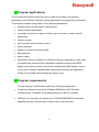
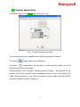
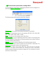
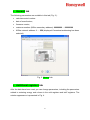
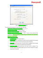
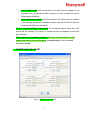
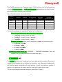
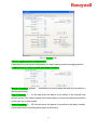
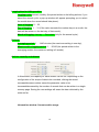
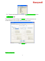
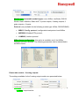
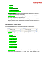
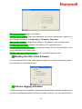
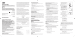
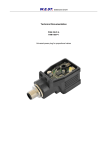
FaunSerwis Configuration Software for EW500 Series Calculators: User Manual Contents: 1. Program applications ...................................................................................................... 3 2. Program requirements .................................................................................................... 3 3. Program appearance ...................................................................................................... 4 4. Transmission parameters configuration .......................................................................... 5 5. Dane ogólne tab .............................................................................................................. 6 6. Dane dodatkowe tab ....................................................................................................... 6 7. Wejścia dodatkowe tab ................................................................................................... 8 8. Archiwa tab ..................................................................................................................... 9 9. Moduły tab..................................................................................................................... 12 10. Optozłącze i Sieć tab .................................................................................................... 16 11. Narzędzia menu options ............................................................................................... 18 11.1 Master data ................................................................................................................... 19 11.2 Failure detection............................................................................................................ 22 11.3 Time – Calculator time and date configuration.............................................................. 24 11.4 Setting meter initial states ............................................................................................. 24 11.5 Display configuration ..................................................................................................... 25 12. Power supply - power supply configuration................................................................... 27 13. Reading the CRC of the program.................................................................................. 28 13.1 Enabling failure recording ............................................................................................. 29 V 1.06, 26/05/2015 1 1. Program applications The FaunSerwis software allows the user to read and configure all operation parameters of the EW500 calculator. All the parameters are grouped by functionality. The software enables configuration of the following parameters: auxiliary inputs and the state of input meters communication parameters removable modules: the type of module, type of protocol, module-specific parameters archive records tariff records and the auxiliary record failure detection display of current and archival data date and time power supply parameters that are related to or influence metering; depending on type, data are additionally protected with a hardware legalisation jumper and HASP dongle of the service centre or the client's jumper and HASP dongle. Access to the client's jumper is possible after opening the housing; the legalisation jumper is accessible after breaking the jumper cover. 2. Program requirements To work properly, FaunSerwis requires the following configuration: A personal computer running the Windows 98/Windows XP/ Windows Vista/Windows 7/Windows 8 operating system and .Net 2.0 or higher. USB port for connecting the optical port or RS232/RS485/M-Bus serial port, depending on the communication module used in the calculator. 2 3. Program appearance FaunSerwis starts in the General tab, as shown in Fig. 1. Fig. 1. FaunSerwis starting window The following buttons are available across all of the program's windows: The button reads data from the calculator. The button writes data to the calculator. To make the button active, you must first read data in the current data. Parameterization of the calculator requires special privileges – this depends on the position of the client's jumper and the legalisation jumper, as well as the type of the HASP dongle (whether it is the client's or service centre's dongle). See the EW500 calculator operation manual, Chapter 4.7. 3 4. Transmission parameters configuration To ensure effective communication, transmission parameters must be configured. Go to the menu Options → Transmission (Fig. 2.). Fig. 2. Go to transmission parameters The following transmission parameters should be configured: Serial port no. – the number of the serial port the device is connected to Baudrate – the transmission rate set in the calculator (300, 600, 1200, 2400, 4800, 9600, 19200, 38400, 57600, 76800, 115200), Parity – the parity set in the calculator (None, Odd, Even), Addresing mode – the type of addressing which will be used for communicating with the meter (Broadcast, Primary address, Secondary address (client number), Enhanced secondary address (serial number)), Address – the devices address, depending on the addressing type selected, Respond timeout – time to wait for response from the calculator in milliseconds. The value is set automatically, based on the transmission rate, Optical port – if data is read via the optical port, check this option for automatic activation of the optical communication port. Checking this option automatically enables broadcast addressing, causing the address set in the calculator to become irrelevant for communication. 4 5. General tab The following parameters are available in this tab (Fig. 3.): calculator serial number date of manufacture, firmware version, customer number (M-Bus secondary address): 00000000 … 99999999 M-Bus network address: 1 … 250 (displayed if broadcast addressing has been selected). Fig. 3. General tab 6. Additional registers tab After the data have been read, you can change parameters, including the parameters related to metering energy and volume in the cold registers and tariff registers. The window appearance is presented in Fig. 4. 5 Fig. 4. Additional registers tab The following parameters can be configured in this tab: Temperature difference insensibility: 0.1...3.0 °C Cooling energy register: active or inactive, Cooling measure threshold: active or inactive, Cooling measure threshold value: 1...30 °C (value of the minimum flow temperature, below the threshold cooling energy is calculated if the temperature difference is appropriate), Tariff 1 type/Tariff 2 type: no tariff active: tariff record inactive power tariff: tariff record active; the tariff record is updated if the average power within a period of time exceeds the power threshold, flow tariff: tariff record active; the tariff record is updated if the average flow within a period of time exceeds the flow threshold, flow temp. tariff: tariff record active; the tariff record is updated if the average supply temperature within a period of time exceeds the supply temperature threshold, 6 return temp. tariff: tariff record active; the tariff record is updated if the average return temperature within a period of time exceeds the return temperature threshold, temp. differenece tariff: tariff record active; the tariff record is updated if the average temperature difference within a period of time exceeds the temperature difference threshold, Tariff 1 threshold/Tariff 2 threshold: the threshold above which the tariff record will be updated. The range of values and the unit depend on the tariff type selected. Tariff register accumulation method: the way of accumulating the tariff energy and volime in the tariff register; proportionally to the exceeded threshold, in total. 7. Additional inputs tab Fig. 5. Additional inputs tab 7 The EW500 calculator has 4 auxiliary inputs. Their functions can be parameterized using the Additional inputs tab. Additional input type: depending on the input number, the following input types can be configured: Tab. 1. Possible auxiliary input configurations Alarm IN Main flow meter communication IN Additional flow meter pulse IN Additional flow meter communication IN + - - - - IN 2 + - - - + IN 3 + + - + - IN 4 + - + - - Auxiliary input No. Pulse IN IN 1 The following settings are available for pulse input configuration: Pulse constant and pulse unit (value of the input pulse): dm3/imp, constant format: xx xxx.y, imp/dm3, constant format: x xxx.yyy, imp/kWh, constant format: x xxx.y. Register resolution (meter record resolution; available for pulse input only): 0.001 m3 / 0.1 kWh, 0.01 m3 / 1 kWh, 0.1 m3 / 0.01 MWh, 1 m3 / 0.1 MWh. Connected device serial no.: 00000000 … 99999999 (information field, the number of the device connected to the additional input). 8. Archices tab The Archives tab allows the configuration of meter data archive recording. The archive recording configuration can be divided into two parts: time and period configuration, and memory space configuration for each archive – that is, the maximum number of records to be written in the archive and the scope of recorded archive data. The tab with example parameter settings is presented in Figure 6. 8 Fig. 6. Archives tab. Archive logging period configuration: Recording time and period configuration for each archive and the averaging period. Logging time for daily, monthly and annual archive: Month of logging: January … December (the month when the data is to be written in the annual record), Day of logging: 1 … 31 (the day when the data is to be written in the monthly and annual record; if the value exceeds the number days in a month, the data will be written on the last day of that month), Hour of logging: 0 … 23 (the time when the data is to be written in the daily, monthly and annual record; recording takes place at full hours), 9 Logging time for billing archive: Logging cycle: annual, monthly (the period written to the billing archive; if you select the annual cycle, a pop-up window will appear prompting you to select the month when the record should take place). Hour of logging: 0 ... 23, Day of logging: 1 … 31 (if the value exceeds the number days in a month, the data will be written on the last day of that month), Month of logging: January … December (only for the annual cycle). Periods: Averaging period: 1 … 1440 minutes (the maximum setting is one day), Minute archive logging period: 1 … 20160 (the period written to the averaging archive; the maximum setting is 2 weeks). Archive capacity and dataset: In this second, the capacity for each archive can be set. Depending on the configuration of the scope of data to be recorded, clicking the record increase/decrease number cases the parameter value to be increased/decreased by the number of records that can be written in a single memory page. Saving the new settings will erase the data collected by the meter so far. Information window: Current archive usage 10 Fig. 7. Sample data displayed after clicking the Number of stored records button. 9. Modules tab Figure 8 presents sample settings in the Modules tab. Which parameters are available depends on the currently selected removable module. Fig. 8. Modules tab Module configuration 11 Module type (removable module type): none, M-Bus, LonWorks, RS232, RS485, Radio WM-Bus, Radio AIUT, 2 pulse outputs, 2 analog outputs, 2 pulse outputs + 2 inputs, Protocol (only available for the following module type: M-Bus, RS232/RS485): MBUS / Config. protocol, configuration/read protocol and M-Bus MODBUS, Modbus RTU protocol, LUMBUS, Lumbus protocol M-Bus frame configuration: this option is available only if the M-Bus interface has been selected. The following parameters can be transmitted in an M-Bus frame: Removable module - 2 analog outputs: The settings available for the 2 analog output module are presented below. Data type (type of the measurement value transmitted to the analog output): none, output inactive 12 power, flow, flow temperature, return temperature, temperature difference. Start of the range: data value corresponding to the range start on the 4 mA or 1 V output, depending on the module type, End of the range: data value corresponding to the range end on the 20 mA or 10 V output, depending on the module type, The range start/end value that can be entered depends on the calculator operating range set during the production process and the instantaneous value for the output, Removable module – 2 pulse outputs The settings available for the 2 pulse output module are presented below. Data type (the type of quantity used for generating pulses on the pulse output 1 or 2): none, output inactive, main energy, cooling energy, tariff 1 energy, tariff 2 energy, main volume, cooling volume, tariff 1 volume, tariff 2 volume. Pulse constant, three pulse values are available. The energy or volume increment values corresponding to a single pulse, which depends on the 13 calculator operating range set during the production process, is presented in Table 2. Tab. 2. Possible pulse value settings for pulse outputs Pulse value for a given setting Range 1 3 4 energy volume 0.1 MJ/pulse 0.1 Mcal/pulse 0.01 kWh/pulse 0.1 dm3/pulse 0.001 GJ/pulse 0.001 Gcal/pulse 0.1 kWh/pulse 0.001 m3/pulse 0.01 GJ/pulse 0.01 Gcal/pulse 1 kWh/pulse 0.01 m3/pulse 0.001 GJ/pulse 0.001 Gcal/pulse 0.1 kWh/pulse 0.001 m3/pulse 0.01 GJ/pulse 0.01 Gcal/pulse 1 kWh/pulse 0.01 m3/pulse 0.1 GJ/pulse 0.1 Gcal/pulse 0.01 MWh/pulse 0.1 m3/pulse 0.01 GJ/pulse 0.01 Gcal/pulse 1 kWh/pulse 0.01 m3/pulse 0.1 GJ/pulse 0.1 Gcal/pulse 0.01 MWh/pulse 0.1 m3/pulse 1 GJ/pulse 1 Gcal/pulse 0.1 MWh/pulse 1 m3/pulse 0.1 GJ/pulse 0.1 Gcal/pulse 0.01 MWh/pulse 0.1 m3/pulse 1 GJ/pulse 1 Gcal/pulse 0.1 MWh/pulse 1 m3/pulse 10 GJ/pulse 10 Gcal/pulse 1 MWh/pulse 10 m3/pulse Removable module – 2 pulse inputs The settings available for the 2 pulse input module are presented below. Additional input no.: Input 1, Input 2, Input 3, Input 4, Inactive (the list of the auxiliary inputs that can be linked to the module pulse input depends on the auxiliary input configuration. An input is displayed on the list if the auxiliary input type set in the Additional inputs tab is other than pulse input. Otherwise, only the Inactive option can be selected. 14 Register resolution (the resolution of updating the additional volume or energy record): 0.001 m3 / 0.1 kWh, 0.01 m3 / 1 kWh, 0.1 m3 / 0.01 MWh, 1 m3 / 0.1 MWh. Pulse constant and pulse unit (value of the impulse): dm3/imp, constant format: xx xxx.y, imp/dm3, constant format: x xxx.yyy, imp/kWh, constant format: x xxx.y. Connected device serial no.: 00000000 … 99999999 (information field, the number of the device connected to the additional input). 10. Optical port and network tab Fig. 9 presents the Optcal port and network tab. In this window, you can set the optical port parameter and the addresses for network communication using the available protocols. 15 Fig. 9. Optcal port and network tab Network configuration: M-Bus address: 1...250 (M-Bus primary address), Customer no. (M-Bus secondary address): 00000000 … 99999999 (client's ID - 8-digit value), LUMBUS address: 0 … 63 (address for communication with the calculator using the Lumbus protocol), MODBUS address: 1 … 247 (address for communication with the calculator using the Modbus protocol). Optical port configuration (optical port communication parameters): Baudrate: 300, 600, 1200, 2400, 4800, 9600, Parity: None, Odd, Even, Standby time of optical port: 1 … 255 s (the optical port activity time if activated manually), 16 Important information: Communication is possible only within a specified period of time, or the activity time. It is recommended that the activity time should be as short as possible to save the battery life. After every transmission, the activity time is extended to the specified value. M-Bus frame configuration: configuration of the scope of data transmitted when communicating via the optical port. Fig. 10 presents the parameters can be transmitted in an M-Bus frame: Fig. 10. Data transmitted in an M-Bus frame 11. Tools menu options 17 12. Primary configuration Whether the parameters in the Primary configuration tab can be saved depends on the current access level. For a detailed description of the parameter access level, see the EW500 calculator operation manual, Chapter 4.7 – Configuration access protection. The parameters are protected with the client's jumper or the legalisation jumper and the client's or the service centre's HASP dongle. The parameters can be always read, but saving them requires special privileges. Calculator (contains information about the calculator configuration): Meter type: heat meter, cold meter, Flow sensor: in flow pipe, in return pipe (the place of the flow meter installation), Application type: closed, closed with leak detection, Energy unit: GJ, MWh/kWh, Gcal, Flow sensor (contains information about the flow meter configuration): Register resolution: given the wide range of the rated flows and pulse constants for the transducers compatible with the calculator, the calculator operation has been divided into 4 ranges. The operation range is defined during the production process for the pulse constant specified in the order and cannot be modified without service privilege and legalisation. Tab. 3. Meter resolution depending on the calculator operation range Range Resolution energy volume 18 flow power 1 0.001 GJ 0.001 Gcal 0.1kWh 0.001 m3 0.001 m3/h 0.1 kW 2 0.01 GJ 0.01 Gcal 1 kWh 0.01 m3 0.01 m3/h 1 kW 3 0.1 GJ 0.1 Gcal 0.01 MWh 0.1 m3 0.1 m3/h 0.01 MW 4 1 GJ 1 Gcal 0.1 MWh 1 m3 1 m3/h 0.1 MW With the client's jumper, it is possible to modify the rated flow and transducer dynamics values, which influence the time to reset the instantaneous flow if there are no pulse for slow impulsing (dm3/pulse). For a programmed operating range, the rated flow can be modified within the range specified in the table below. The following parameters can be configured for the flow transducer: Dynamic range: 1/50, 1/100, 1/250, Nominal flow: see table below, Pulse constant: see table below. Tab. 4. Possible of the impulse and flow constant values for each calculator operating range range pulse constant pulse constant [imp/dm3] [dm3/imp] rated flow [m3/h] 1 1 ... 10 300 ... 25 0.6 ... 6 2 10 ...100 25 ... 2.5 1 ... 60 3 100 ... 1000 2.5 ... .25 10 ... 600 4 1000 ... 10000 .25 ... .01 100 ... 3000 Temperature sensor (contains information about the configuration of temperature measurement inputs): Sensor type: Pt500, Pt100, Pt1000 (the type of sensors compatible with the calculator; the setting is hardware-programmed and cannot be modified), Connection type: 2-wire, 4-wire (the type of sensor connection). 19 12.1 Failure detection configuration Failure detection is presented below: Reverse temperature difference error detection Error detection: active, inactive, Max. flow exceed error detection Error detection: inactive, active – based on instantaneous value, active – based on average value (in the averaging period), Flow threshold: 1.5...7500 m3/h. No flow error detection Error detection: inactive, active – based on average value (calculated based on the average temperature and flow values within the averaging period), Time to detect the error: 1 … 24 h (the minimum time for which a temperature difference exceeding the threshold and a flow rate lower than the threshold must occur for the no flow error alert is generated), Temp. difference threshold: 1 ... 175 K, 20 Flow threshold: the value that can be specified depends on the pre-set calculator operating range, as specified in Table 3. Leak in system error detection Error detection: inactive, active – based on volume difference, active – based on mass difference, Error signaling threshold: depending on the range selected (the volume or weight difference value threshold, above which the leak error alert is generated), Time to detect the error: 1 … 24 h (the leak error check cycle) Burst in system error detection Error detection: disabled, enabled, Error signaling threshold: 10...100 % (per cent of the rated flow value above which the error alert is generated) Time to detect the error: 10 … 360 seconds (the leak error check cycle) General settings Error indication by the LED, check this option to select what failures will be indicated by a LED (only available for the device version with mechanic buttons) Error logging: indicated whether failure recording is enabled. Read-only. 21 12.2 Time – Calculator time and date configuration The user can set the current date and time using a calendar and a time change field. Daylight saving auto change: if checked, the automatic daylight saving time change is enabled, Local time set: if checked, the system time (current date and time in the system) will be set in the calculator. 12.3 Setting meter initial register values You can set the initial states of the calculator registers. Depending on the current access level, you can set or reset selected calculator registerrs. See the Operation manual for more details. Register type: the value of the auxiliary input 1,2,3,4 (settings available without a HASP dongle), Value: initial state of the meter record; choose any value from the available range. 22 12.4 Display configuration The calculator features a number of settings for configuring the scope of data displayed on the LCD screen and the way they are displayed. You can configure the scope of data displayed in the archive group and the minute, hourly, daily, monthly and annual archives. You can also define the maximum number of recent records to be displayed. Insignificant zeros displayed: check to display non-leading zeros in energy and volume records on the LCD screen, Automatic return to main energy display: check to enable automatic return to the main energy display after a pre-set time, Time of automatic return to main energy display: 1 … 255 seconds (idle time after which the main menu screen will return). Main menu scope You can specify which records will be available on the LCD screen via the main menu (group 01). For the data to be displayed on the LCD screen, the relevant record must be active; example: the cold energy and volume record will be displayed provided that it is checked in the window below and activated in the Additional registers tab. 23 Statistic group scope You can specify what data will be available on the LCD screen in the statistic data menu (group 02). The scope of the archival data displayed: the variable archive, daily archive, annual archive, hourly archive and monthly archive. 24 You can enable/disable the display of all peak, average and instantaneous values independently for each archive type whose data are available on the LCD screen. The scope of the values that can be configured depends on the configuration of the data scope recorded in the archive (the list does not include any data not recorded in the archive). Maximum number of records to display You can configure the number of recent archive records that will be displayed. The setting cannot exceed the maximum number of possible records. 13. Power supply - power supply configuration In this window, you can read and modify the type of calculator power supply, read the supply voltages and the battery operation time. 25 Main power supply: Battery, AC adapter, Backup power supply: Read-only parameter set by the manufacturer; depends on the calculator production: 1/2 AA battery, CR battery, SuperCap Main battery voltage: voltage of the battery or AC adapter in the calculator base, Backup battery voltage: voltage of the battery in the calculator cover, Backup battery work time limit: the maximum battery life time for the battery in the cover (depends on the battery type), Backup battery work time counter: current calculator operation time. 14. Reading the CRC of the firmware You can read the CRC of the whole program space, its certified (metrological) part or its functional (non-metrological) part. 15. Failures logging activation Failure recording is automatically enabled after the calculator has been installed and a non-zero instantaneous power has been recorded. However, you can activate failure 26 recording in the archive and enable the counting of post-error operation time using the option below. 27 Environmental and Combustion Controls Honeywell GmbH Hardhofweg 74821 Mosbach, Germany Phone +49 (6261) 810 Fax +49 (6261) 81393 www.honeywell.com EN5H-0462GE25 R0515 May 2015 (Rev. A) © 2015 Honeywell International Inc. Subject to change • All rights reserved Created for and on behalf of the Environmental and Combustion Controls Division of Honeywell Technologies Sàrl, Z.A. La Pièce, 1180 Rolle, Switzerland or by its Authorised Representative. 28