1
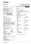
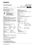
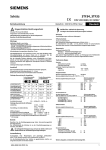
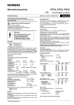
SIRIUS 3TB46, 3TB47, 3TB48, 3TB50 Contactors Operating Instructions English Hazardous voltage. Will cause death or serious injury. Replacement of the main contacts Pull the moving contact (including the leaf spring on the 3TB47, 3TB48 and 3TB50) out by hand. Raise the bridge holder and insert a new contact (complete with leaf spring on the 3TB47, 3TB48 and 3TB50). Make sure that the contact can move easily in the closing direction. Fixed contact: Undo the fixing screw with an hexagon-socket wrench. Replace both contact and fixing screw and firmly tighten the new contact. Í Tightening torque. Disconnect power before working on equipment. Changing the auxiliary contact blocks If necessary exchange the complete auxiliary contact block. Read and understand these instructions before installing, operating, or maintaining the equipment. ! DANGER Reliable functioning of the equipment is only ensured with certified components. Contactor, a.c. operated ¿ Rated operating current Ie / AC1 (at 55 °C) À Max. motor output rating (AC2, AC3) Control voltage marked on coil, operating range 80 to 110 % rated voltage. Á Maximum fuse ratings for contactors without overcurrent relays (L.V. HRC fuses) I No contact welding II Slightly welded but easily seperable contacts, see VDE 0660 § 73b Back-up fuse ratings for contactors with overcurrent relay are specified on the relay: value II to table Á must not be exceeded. Motor protection afforded by overcurrent relay 3UA42, 3UA43 or 3UA58. Use relays with self reset for momentary-contact controlled contactors and with hand reset for maintained-contact controlled contactors.Check the note on the relay. Set the relay scale to the rated motor current. Mounting Mount on a plane surface. Fit contactor inside a housing if it is exposed to contamination, dust or an aggressive atmosphere. Â Maximum tilt Coil connection on top Maximum conductor cross-sections (screw terminals) for contactors without motor protection feature (for contactors with motor protection feature see Operating instructions "Overcurrent relays") Main conductors: Ã solid Ä stranded with cable lug Å busbars Æ terminal screws (supplied loose with 3TB48, 3TB50) Ç Tightening torque Auxilary conductors: È solid É finely stranded with end sleeves Ê terminal screw Ë Tightening torque Ì Connection of the main conductors: 3TB46, 3TB47 correspond with version II 3TB48, 3TB50 correspond with version I For looking the nut spring washers are required (a). The toothed washer (b) keeps the bolt from turning. (Securing the bolt head is unnecessary) Maintenance Remove dust by suction! Discoloured and rough contacts are still serviceable and should not be dressed nor greased. Replace contacts whose contact pieces have eroded so much that supports can be seen. In case of non uniform erosion it is permissible to replace individual contact pieces. Check the main contacts after a short-circuit and separate them with a screwdriver, if necessary. Replace damaged arc chute. 2 Order No.: 3ZX1012-0TB46-2AA1 Tightening torque: 0,8 – 1,2 Nm. Replacing the arc chute Undoing the quick fastening device: Push in the two pins with a screwdriver and turn them through 90 °. The arc chute can now be detached. Fixing: Fit the arc chute, push in the two pins as far as they will go, turn them through 90 °, and ensure that they engage. Replacing the coil Î 3TB46: Remove the two fixing screws (1) of baseplate (5) and lift off the contactor base (2). Take out coil (3) together with its two terminal connections (4). Fit a new coil and place its two terminals in the cutouts in the baseplate. Refit the contactor base (2) and firmly bolt on the baseplate (5). Ï 3TB47, 3TB48, 3TB50: Undo the two screws (1) fixing the bottom plate (4). Lift off contactor base (2). Replace coil (3). Fit the contactor base and screw on the bottom plate. Spare parts Ñ Main contacts Ò Arc chute Ó Auxiliary contact block left 21 Auxiliary contact block right NC contact with longer make-time for d.c. economy circuit 1) Diagrams Terminal markings to EN 50012, markings to DIN 46199 in brackets. A.C. operated 22 with auxiliary contacts 2 NO + 2 NC 23 with auxiliary contacts 4 NO + 4 NC 24 Momentary-contact actuator 25 Maintained-contact actuator D.C. operated 26 with auxiliary contacts 2 NO + 2 NC 27 with auxiliary contacts 3 NO + 3 NC 28 Momentary-contact actuator 29 Maintained-contact actuator A1 / A2 Closing coil B1 / B2 Hold-in coil (not with 3TB46) Q 3TB contactor V1 / V2 rectifier (in the coil) Contactor will not pick up if polarity is incorrect, interchange connections. (A1 and B1 always to L+) Dimensions (in mm) Minimum clearance from 31 insulated parts 32 earthed parts Dimensions of moulded plastic arc chute 2) 30 t