1
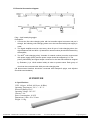
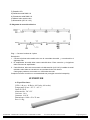
E: Electrical Connection diagram
Plug----2pin female plug spigot
Description:
1. Connect the first color-changing tube with led controller signal connector and put it
through, the following color-changing tubes are to be connected with power supply in
order;
2. The signal amplifier must be used every other 60 pcs of color-changing tubes, the
signal between 60X and 60X+1 (X stands for natural number) should be enhanced by
the amplifier;
3. The 90Xth color-changing tube( X stands for natural number) must be reconnected
with power supply (240V) and the power output should be stopped by P3. The
power (240V/50Hz) and signal output connector for the last tube should be stopped
by Teminator (1 pc 120 Ω resistor inside) in order to prevent water. Each group of
circuit can be connected with 1000 pcs color-changing tube
(All disconnected interface should be connected with waterproof spigot, and all-joints
should be used sealants)
SUPERTUBE
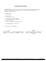
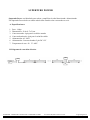
A: Specifications:
LED: 144 pcs ( 48 Red, 48 Green, 48 Blue)
Operating Temperature: -20 º C + 45 º C
Protection Rating: IP 65
Operating Voltage: DC 12V
Current: 1.4 A
Power Consumption: 16.8 W
Dimensions: 1000 x 50 x 25 mm
Weight: 1.0 Kg.
SUPERTUBE - SUPERTUBE CONTROLLER - SUPERTUBE POWER
User Manual/Manual de Usuario
Page/Página 5