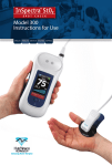
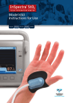
1
Model 650 User Manual ENGLISH Français Deutsch Italiano Español Model 650 User Manual ENGLISH Français Deutsch Italiano Español InSpectra™ StO2 Tissue Oxygenation Monitor Model Number: 650 CAUTION: Federal Law (USA) restricts this device to sale by, or on the order of, a physician. Serial Number: _________________________________ (Record by purchaser) Purchase Date: _________________________________ (Record by purchaser) Manufactured by: Hutchinson Technology Inc. BioMeasurement Division 40 West Highland Park Drive NE Hutchinson, MN 55350-9784 USA Service Centers United States and Canada Authorized European Representative Hutchinson Technology Inc. BioMeasurement Division 40 West Highland Park Drive NE Hutchinson, MN 55350-9784 USA Hutchinson Technology Inc. European Business Office IJsselburcht 3 6825 BS Arnhem The Netherlands Telephone: 800.419.1007 or 320.587.1926 Fax: 320.587.1555 Telephone: +31 26 365 33 71 Fax: +31 26 365 33 72 Email: [email protected] Website: www.htibiomeasurement.com Email: [email protected] Website: www.htibiomeasurement.com US Patents: 5879294, 6487343, 6473632, 6892006; others pending. 0086 Copyright 2010. Hutchinson Technology Incorporated. Printed in the USA. All Rights Reserved. RX ONLY. InSpectra™ is a trademark of Hutchinson Technology Incorporated. InSpectra is a registered trademark of Hutchinson Technology Inc. in the United States of America, the European Community, Canada, China and Japan. ENGLISH 5009083 E 2/10 Table of Contents 3 Table of Contents ENGLISH InSpectra™ StO2 Tissue Oxygenation Monitor........................................................................ 4 Introduction............................................................................................................................ 4 Components.......................................................................................................................... 4 Features................................................................................................................................. 5 Intended Use/Indications for Use.......................................................................................... 6 Contraindications................................................................................................................... 6 Safety..................................................................................................................................... 6 Safety Notifications – Warnings............................................................................................ 6 Safety Notifications – Cautions............................................................................................. 6 Controls, Indicators, and Symbols........................................................................................ 7 How To Use.................................................................................................................................. 9 InSpectra™ StO2 Tissue Oxygenation Monitor.................................................................... 9 Set Up.................................................................................................................................... 9 Power On............................................................................................................................... 10 Calibration.............................................................................................................................. 10 InSpectra™ StO2 System Check.......................................................................................... 11 Battery................................................................................................................................... 11 Fan......................................................................................................................................... 11 Monitor LCD Screen.............................................................................................................. 12 Status Bar.............................................................................................................................. 12 Data Display.......................................................................................................................... 12 Menu Bar............................................................................................................................... 13 Main Menu (Home)................................................................................................................ 13 Set-Up Menu......................................................................................................................... 13 InSpectra™ StO2 Alarm Menu.............................................................................................. 15 Patient Monitoring...................................................................................................................... 16 InSpectra™ StO2 Sensor...................................................................................................... 16 Positioning the InSpectra™ StO2 Sensor............................................................................. 17 Data Display.......................................................................................................................... 18 Power Off............................................................................................................................... 20 Cleaning the System............................................................................................................. 20 Technology.................................................................................................................................. 21 Technology of the InSpectra™ StO2 Tissue Oxygenation Monitor....................................... 21 Tissue Hemoglobin Index (THI)............................................................................................ 22 References............................................................................................................................ 22 Data Transfer............................................................................................................................... 23 InSpectra™ StO2 Case Graphing Software.......................................................................... 23 Live Data Stream................................................................................................................... 24 Technical Specifications........................................................................................................... 25 Maintenance................................................................................................................................ 28 Maintenance Safety............................................................................................................... 28 InSpectra™ StO2 System Check.......................................................................................... 28 Charging the Battery............................................................................................................. 29 Replacing the Battery............................................................................................................ 29 Software Updates.................................................................................................................. 29 Disposal of Components....................................................................................................... 29 Troubleshooting.......................................................................................................................... 30 Troubleshooting Guide.......................................................................................................... 30 Error Messages..................................................................................................................... 31 Replacement Parts and Accessories....................................................................................... 32 Warranty ..................................................................................................................................... 33 Technical Addendum................................................................................................................. 34 Guidance and Manufacturer’s Declaration – Electromagnetic Emissions............................ 34 Guidance and Manufacturer’s Declaration – Electromagnetic Immunity ............................ 35 Recommended Separation Distances Between Portable and Mobile RF Communications Equipment and the InSpectra™ StO2 Tissue Oxygenation Monitor................................................................................................. 37 InSpectra StO2 Tissue Oxygenation Monitor – Alarm System IEC 60601-1-8................... 38 Index............................................................................................................................................. 42 Introduction The InSpectra™ StO2 Tissue Oxygenation Monitor uses near infrared spectroscopy to measure local oxygen saturation of hemoglobin in tissue (StO2), and an index of total hemoglobin (THI) in the tissue being monitored. The absorption spectrum of light remitted from a tissue sample varies mainly with oxyhemoglobin and deoxyhemoglobin concentration. The percent of StO2 is a measure of hemoglobin oxygen saturation of blood contained in the volume of tissue illuminated by the near infrared light. Tissue Hemoglobin Index (THI), as measured in a range of 1–99 by the InSpectra StO2 Tissue Oxygenation Monitor, is a quantified value that corresponds to the amount of hemoglobin present within the volume of tissue illuminated by the patient contact sensor optical signal. The InSpectra StO2 Tissue Oxygenation Monitor uses tissue absorbance values at different wavelengths. A reference measurement and scaling of the second derivative absorbance spectrum provides a means of internal calibration. The InSpectra StO2 Tissue Oxygenation Monitor therefore does not require calibration before each use. Components The InSpectra™ StO2 Tissue Oxygenation Monitor has two (2) main components and a power cord: 1. T he Monitor and Optical Cable. The monitor contains an LCD screen 1 , light detection circuitry, a microcontroller, cooling fan, optical cable, back-up battery, and internal software. Light emitting diodes in the monitor are the light source. The monitor has an internal lithium ion battery and two external data ports. It is equipped with an adjustable C-clamp for attachment to an IV pole. The optical cable 2 , which is permanently connected to the monitor, contains one set of optical fibers to transmit light to the tissue, and a second set of optical fibers that receive light from the tissue and return it to a photosensitive detector in the monitor. 2. The InSpectra™ StO2 Sensor 3 . The single-use InSpectra StO2 Sensor, when connected to the optical cable, conducts the optical signal to the patient and back to the monitor. The sensor has a shield to protect the measurement from ambient light interference, has an metal reinforced cable to protect the optical fibers, and has an adhesive surface to facilitate attachment of the sensor to the patient for continuous monitoring. 3 T he InSpectra StO2 Tissue Oxygenation Monitor and Sensor are latex free. ENGLISH 3. T he Power Cord 4 4 4 1 2 . The power cord connects to an AC electrical source (120 USA / 220 EU). InSpectra™ StO2 Tissue Oxygenation Monitor figure 4.1 Features of the InSpectra™ StO2 Tissue Oxygenation Monitor Start-up Time Approximately 20 seconds. No calibration required. Ready to use with two button pushes. InSpectra™ StO2 Sensor Self-stick, highly conforming sensor built into disposable terminal cable end; can stay on patient and be reconnected to other InSpectra StO2 Monitors throughout the hospital. Parameters Displayed InSpectra™ StO2 System Measurement and Tissue Hemoglobin Index (THI) Display Large LCD color screen with trended display and THI signal indicator. History available with 30-minute, 1-, 4-, and 8-hour selectable views. Alarm Programmable upper and lower alarm limits, alarm mute,visual upper and lower alarm settings on display screen. Size 32cm (12.5 in) x 27cm (10.5 in) x 22cm (8.5 in) Weight 4kg (9 lbs) Fluid Resistance Designed and tested to meet splash and drip resistance needs of trauma and ED environment. Display screen resists harsh cleaning fluids. Ruggedness Monitor: polymer overmold designed and tested for drops and rugged trauma and ED environment. Shatterproof display screen. Optical Cable: metal reinforced and endurance tested to withstand trauma and ED environment. Portable Battery or AC powered. Minimum two-hour battery life. Indicator shows remaining battery life. Light weight. Mounts on IV pole; visible and stable during transport. Saved Data History Continuous data capture up to 96 hours Data Transfer With InSpectra™ StO2 Case Graphing Software: Up to 96 hours of previous monitoring data can be downloaded to PC. With Live Data Stream: directly stream continuous text files to PC on InSpectra StO2 Measurement and THI through RS232 or USB ports. Optical Cable Length 3m (10 ft) Measurement Depth 15mm (0.6 in) Languages English, French, German, Italian, Spanish ENGLISH 5 InSpectra™ StO2 Tissue Oxygenation Monitor Intended Use/Indications for Use The InSpectra™ StO2 Tissue Oxygenation Monitor is intended for use as a noninvasive monitoring system that measures an approximated value of percent hemoglobin oxygen saturation in tissue (StO2). The InSpectra StO2 Tissue Oxygenation Monitor is indicated for use in monitoring patients during circulatory or perfusion examinations of skeletal muscle or when there is a suspicion of compromised circulation. Contraindications No contraindications are known. Safety Carefully read and review this entire manual before using to fully understand the device, its operation, and the potential risks to user and patient before use of the InSpectra™ StO2 Tissue Oxygenation Monitor. Illustrations shown in this manual are intended to familiarize the user with the device. The values shown are intended solely for purposes of example. Safety Notifications – Warnings O WARNINGS alert the user to potential serious outcomes (death, injury, or adverse events) to the patient or user and contain information the user should know to avoid injuring patients and personnel. O WARNINGS help you to: • Identify the hazard. • Avoid the hazard. • Recognize the consequences. Safety Notifications – Cautions CAUTIONS indicate conditions that may lead to malfunction or failure of the InSpectra™ StO2 System. ENGLISH RX Only 6 InSpectra™ StO2 Tissue Oxygenation Monitor Controls, Indicators, and Symbols InSpectra™ StO2 Tissue Oxygenation Monitor: FRONT 3 2 1 4 5 12 6 8 12 9 10 7 11 figure 7.1 1 Alarm mute button 7 THI signal bars (Tissue Hemoglobin Index) 2 Clock 8 THI value (Tissue Hemoglobin Index) attery charge indicator (shown only when 3 B operating on battery power) 9 Time interval attery charge indicator (shown only when 4 B operating on AC power) 10 InSpectra StO2 System Measurement attery fully charged indicator (shown only when 5 B operating on AC power) 11 Touchpad buttons (5) 6 LCD panel 12 Prongs for wrapping optical cable (4) ENGLISH 7 InSpectra™ StO2 Tissue Oxygenation Monitor Controls, Indicators, and Symbols InSpectra™ StO2 Tissue Oxygenation Monitor: BACK 1 4 7 2 5 6 3 8 14 9 10 12 11 13 15 16 ENGLISH figure 8.1 1 ON/OFF button 9 Patient Electrical Isolation 2 Serial number 10 IPX1 (drip proof equipment) 3 Power receptacle 11 C-clamp 4 Equipotentiality 12 Product Manufacturer 5 Serial port 13 Authorized European Representative 6 USB port 14 Caution: consult accompanying documents 7 Alternating Current (AC) 15 EU WEEE Crossed Out Dust Bin 8 Voltage and Frequency Specs 16 Electrical Certification 8 InSpectra™ StO2 Tissue Oxygenation Monitor InSpectra™ StO2 Tissue Oxygenation Monitor 1. Confirm that the following components are present: 1 InSpectra StO2 Tissue Oxygenation Monitor with permanently attached optical cable 2 3 InSpectra™ StO2 Sensor 4 Power cord 5 InSpectra™ StO2 System Check 6 InSpectra™ StO2 Case Graphing Software User Manual 7 InSpectra™ StO2 Model 650 User Manual 2. Record the Serial Number, located on the back of the monitor in the upper right corner, on the inside front cover of the User Manual. 3. Record the Purchase or Acquisition Date in the section provided inside the front cover of the User Manual. 4 1 3 2 5 6 figure 9.1 7 Set-Up The InSpectra™ StO2 Tissue Oxygenation Monitor can be set on a flat surface next to the patient or mounted on an IV pole using the C-clamp located in the recessed cavity 1 in the back of the monitor. A knob 2 on the right side of the monitor opens and closes the clamp. To mount on IV pole: 1. Turn knob 2 counter clockwise to open the C-clamp 1 completely. 2. Position on the pole. 3. Turn knob clockwise to tighten the C-clamp and secure the monitor on the IV pole. O WARNING: To ensure patient safety: • Secure the InSpectra StO2 Tissue Oxygenation Monitor tightly to the IV pole. • Do not place the InSpectra StO2 Tissue Oxygenation Monitor in any position that might allow it to fall on the patient. • Carefully route cabling to reduce the possibility of patient entanglement or strangulation. • Possible tripping hazard. Do not allow the InSpectra StO2 Monitor Optical Cable to lie on the floor where it may become damaged or pose a tripping hazard. 1 2 CAUT ION: • Repeated exposure to ionizing radiation can figure 9.2 cause cumulative damage to the InSpectra StO2 Monitor Optical Cable glass fibers resulting in inaccurately low InSpectra StO2 System Readings. To avoid damage to the Optical Cable, whenever possible: • Position the Optical Cable out of the direct X-ray imaging area. • Disconnect and position the Optical Cable out of the CT imaging area. • Possible inaccurate measurements. Do not lift or carry the InSpectra StO2 Tissue Oxygenation Monitor by the optical cable; doing so could result in damage to the cable and inaccurate measurements. ENGLISH 9 How To Use Power On The InSpectra™ StO2 Tissue Oxygenation Monitor operates using AC or battery power. O WARNING: • Explosion hazard. Do not use the InSpectra StO2 Tissue Oxygenation Monitor in the presence of flammable anesthetics or gases. • Possible electrical shock hazard: – Do not connect to a power source if the power cord on the InSpectra StO2 Tissue Oxygenation Monitor is damaged. – Do not simultaneously touch a patient and an external device, such as a computer, that is connected to the InSpectra StO2 Tissue Oxygenation Monitor through the USB port or the RS232 port. CAUT ION: • The use of sensors, cables and accessories other than those specified may result in damage and inaccurate readings. • Use only the power cord supplied with the InSpectra StO2 Tissue Oxygenation Monitor. 4 To operate on AC power: 3 1. Insert the grounded plug into an AC outlet receptacle (120 volt USA / 220 volt EU). The fan will turn on. 2. A light between the battery symbols on the front of the monitor will illuminate to indicate the status of the battery. 1 Battery is charging – yellow light 2 Fully charged battery – green light 3. Push the ON (top) portion of the ON/OFF button on the back of the monitor. A sequence of beeps lasting about 30 seconds will sound indicating a successful power-on self-test. 3 The LCD screen will illuminate. 4 The hour clock in the left corner of the status bar (top) on the LCD screen will appear. 1 2 figure 10.1 Calibration ENGLISH The InSpectra™ StO2 Tissue Oxygenation Monitor does not require calibration before each use. The InSpectra StO2 Tissue Oxygenation Monitor uses tissue absorbance values at different wavelengths. A reference measurement and scaling of the second derivative absorbance spectrum provide internal calibration. 10 How To Use InSpectra™ StO2 System Check The System Check provides a method to quickly check the function of the monitor and its optical cable to accurately calculate the InSpectra StO2 System Measurement and THI. • If the InSpectra™ StO2 Tissue Oxygenation Monitor was used during X-ray or Computerized Tomography, perform a System Check to verify that your InSpectra StO2 System is reading within the stated specifications. (See InSpectra StO2 System Check section, page 28) • It is recommended the System Check be used whenever damage is suspected to the InSpectra StO2 Tissue Oxygenation Monitor or optical cable. • The System Check values for the InSpectra StO2 Measurement and THI will not be recorded to the historical data. Battery A lithium ion battery is installed in the InSpectra™ StO2 Tissue Oxygenation Monitor at the factory. NOTE: To ensure maximum battery runtime it is recommended to fully charge the battery: • Upon receipt of the InSpectra StO2 Tissue Oxygenation Monitor. • If the battery has not been fully charged in the past 30 days. • The battery is specified for a minimum of two (2) hours of use when fully charged. • Replacement every two years by a qualified service technician is recommended. 2 To operate on battery power: 1. Unplug the AC cable, if the InSpectra StO2 System is running currently. 2. P ush the ON (top) portion of the ON/OFF button on the back of the monitor to turn power on. A sequence of beeps lasting about 30 seconds will sound indicating a successful power-on self-test. 1 The LCD screen will illuminate. 2 The hour clock in the left corner of the status bar (top) on the LCD screen will appear. 3 The battery charge indicator appears in the right corner of the status bar. NOTE: 1 3 4 figure 11.1 • To ensure continuous monitoring, connect to AC power immediately when the battery charge indicator shows one red bar remaining. • To extend battery runtime, ensure full charge as indicated by the green indicator light 4 or the full battery indicator bars 3 and decrease the LCD brightness. [see Main Menu (Home), page 13] 3 Fan The internal fan is used for cooling when charging the battery using AC power. The fan: • Does not run on battery power. • Runs continuously when the monitor is operating on AC power. • Draws air for cooling through the inlet grill on the bottom of the monitor. CAUT ION: Do not block the inlet grill on the bottom of the monitor when plugged into AC power as this may cause the monitor to overheat. ENGLISH 11 How To Use Monitor LCD Screen InSpectra™ StO2 Tissue Oxygenation Monitor LCD screen consists of three areas: 1 Status bar (top of the screen) 2 Data display (middle of the screen) 3 Menu bar (bottom of the screen) 1 2 Status Bar 3 The status bar at the top of the LCD screen can display the following messages from left to right: figure 12.1 1 2 3 4 5 figure 12.2 ime 1 T The hour clock is set at the factory to Central Standard Time (CST). Set time is a 24-hour clock in HH:MM (19:48). rror Message 4 E Error messages are highlighted in white text on cyan background or black text on yellow background. NOTE: To set the clock to local time, follow the directions in the Set-Up Menu. 2 InSpectra StO2 Alarm Message Alarm message is highlighted with flashing text on a yellow background. A high or low InSpectra StO2 Alarm will occur only if the InSpectra StO2 System Measurement extends beyond the user-determined upper or lower limit. See InSpectra StO2 Alarm Menu section attery Charge Indicator 5 B The status of the battery charge shows when operating on battery power. to set upper and lower limits. ensor Connected 3 S The Sensor Connected message will show at all times when the InSpectra™ StO2 Sensor is connected to the optical cable. ENGLISH Data Display See Patient Monitoring section, page 18. 12 How To Use Menu Bar The menu bar provides access to the set-up parameters. • Menu tabs have either text or icons. • Choices are made by pushing the touchpad buttons below the LCD screen. Main Menu (Home) Main Menu is the Home menu (default) Allows the user to access: 2 Set-Up parameters 1 3 Alarms 2 3 4 5 4 History of data 5 The brightness of the LCD 6 screen can be adjusted using this tab selection. figure 13.1 • The default setting on AC power is bright. • The default setting on battery power is dim. 6 Use the touchpad buttons below the LCD screen that coincide with the tab to make selections in each menu. 1 Set-Up Menu Allows the user to set: 1 Time Range 2 Language 1 2 3 4 3 Clock 4 The Home tab returns the user to the Main Menu. • The Home icon does not appear on the Main figure 13.2 Menu as this is the Home location. • Press Home to confirm any menu selection. • Within a menu, the user must use the Home tab to return to the Main Menu and start over in any sequence. 1. Set-Up / Time Range Time Range refers to the intervals of time displayed on the live data display graph. 1 2 5 6 5 3 4 hours 30 minutes 4 8 hours 1 hour 2 3 4 1 The default time range is one (1) hour with tick marks at 15 minute intervals. The time range on the data display graph changes with selection of a new time range from the menu. Press Home to confirm selection and return to the Main Menu. 6 figure 13.3 ENGLISH 13 How To Use Menu Bar (continued) 2. Set-Up / Language Any one of five (5) languages can be selected in this menu. 1 English (default) 2 French 3 German 4 Italian 5 Spanish Italian and Spanish appear in a second menu by pressing the forward (>>) button in the first menu. 6 Press Home to confirm selection and return to the Main Menu. 1 2 3 6 figure 14.1 4 5 6 figure 14.2 ENGLISH 3. Set-Up / Clock 1 The hour clock in the upper left hand corner of the LCD screen should be set to local time. 2 Select (-) hour button to go back one hour 3 Select (+) hour button to go forward one hour 4 Select (-) minute to go back one minute 5 Select (+) minute to go forward one minute 6 Press Home to confirm the change and return to the Main Menu. 1 2 3 4 5 6 figure 14.3 Clock and Date features: • When the hour is increased past 23, the hour displayed will be 0 (zero) and the date will increment. • When the hour is decreased below 0 (zero), the hour displayed will be 23, and the date will decrement. • The hour will not increase or decrease when the minute rolls past 0 (zero) or 59. • The date can be set under this tab to the YYYY-MM-DD format by incrementing or decrementing the time. 14 How To Use InSpectra™ StO2 Alarm Menu • There are no predefined alarm limits for InSpectra StO2 System Measurement. • The upper and lower thresholds are set by the user. • An intermittent alarm sounds when InSpectra StO2 Measurements extend beyond the user-determined upper or lower threshold. 1 NOTE: Alarm limits are adjustable for monitoring InSpectra StO2 Measurements for a particular patient. When the monitor powers off for any reason, the alarm limits reset to 0 (zero) and 99 percent, which are equivalent to disabling alarm conditions. If the monitor is not turned off between patients, the operator should check that the current alarm values are appropriate. 2 3 4 figure 15.1 InSpectra StO2 Alarm Set-Up Press Alarm at the Main Menu to set upper or lower 1 alarm limit thresholds. • Adjust the upper and lower alarm limits in increments of 1 or 5. 1 Upper and lower alarm limits are shown with a red 2 marker and the value in red on the vertical axis of the display graph. 2 Decrease in increments of 5 or 1 by pressing the (- 5) or (- 1) button on the menu. 3 Increase in increments of 1 or 5 by pressing the (+ 1) or (+5) button on the menu. 4 Press Home to confirm selection and return to the Main Menu. 3 4 figure 15.2 Alarm Mute Button The speaker 1 for the alarm is located on the left side of the monitor below the fan outlet grill. 2 Press the mute button located in the upper left corner on the front of the monitor to silence the alarm. • The alarm will remain silent for two (2) minutes and will then reactivate and sound again if the alarm condition continues to exist. • The alarm signal state will inactivate automatically when the alarm condition ceases to exist. 2 3 3 1 figure 15.3 ENGLISH 15 How To Use InSpectra™ StO2 Sensor To begin patient monitoring, an InSpectra StO2 Sensor must be connected to the optical cable and adhered to patient tissue. See placement instructions on the next page. 2 1 The Sensor has the following parts: 1 Connector 2 Sensor shield figure 16.1 Connect the InSpectra StO2 Sensor 1 Remove the InSpectra StO2 Sensor from the package. 1 Align the two raised lines on the optical cable connector and the raised line on the sensor connector. 2 Insert the sensor connector into the optical cable connector with the raised lines aligned. 3 Rotate the collar towards the locked symbol to close. 4 The “Sensor Connected” message will display on the screen in the status bar and the system is now ready for patient monitoring. The sensor does not require 4 calibration. 2 Delete All Historical Data The prompt, “Delete all historical data?” will appear immediately in the data display area 1 to allow save or deletion of historical data stored in the monitor from a previous use. 1 This message will appear when: • A sensor is initially connected or reconnected to the optical cable. • The monitor is powered up with a sensor already connected. • The Delete Data menu is selected from the Set Up / History menu. 2 Select Yes to clear all historical data. 3 Select No if you are resuming monitoring on the same patient and/or wish to save previous patient data. 4 Selecting Home is the same as No, and returns to the main menu. figure 16.2 1 ENGLISH 2 16 Patient Monitoring 3 3 4 figure 16.3 Positioning the InSpectra™ StO2 Sensor The InSpectra StO2 Sensor is placed on the thenar eminence (the fleshy mass on the palmar surface of the hand at the base of the thumb 1 see figure 17.1) and secured using the adhesive on the face of the sensor shield. 1 1. Clean and dry the base of the thumb on the palmar side 1 and around the top of the thumb on the back of the hand. CAUTION: The InSpectra StO2 Sensor is for external use only and should only be used on intact tissue. 2. Position the InSpectra StO2 Sensor on the patient’s thenar eminence. The sensor face with the black circles 2 is positioned against the skin along the axis of the dotted line 1a as shown in figure 17.1. NOTE: The window in the release liner of the InSpectra StO2 Sensor enables the user to check the placement before adhering the sensor to ensure that an adequate tissue hemoglobin index (THI) signal is present. A THI greater than 5.0 indicates sufficient hemoglobin to obtain an adequate signal in most circumstances. 3. While holding the sensor in place, grasp one of the white release liner tabs 3 and remove from the sensor shield. 4. Press and conform this side of the sensor shield to the patient. 3 5. Remove the other white release liner tab 3 and conform the remaining part of the sensor shield to the patient. 6. The shield of the InSpectra StO2 Sensor curves around the base of the thumb on the palmar side and around the top of the thumb on the back of the hand. See figure 17.3 for proper position on the patient’s hand. 7. Secure the sensor cable to the patient’s arm using an appropriate medical adhesive tape. 1a figure 17.1 2 figure 17.2 NOTE: The sensor can be used with any other available InSpectra StO2 Tissue Oxygenation Monitor for continued patient monitoring. The sensor does not require calibration. O WARNING: • Disconnect and remove the InSpectra StO2 Sensor from the patient prior to magnetic resonance imaging (MRI) scanning. • Possible skin irritation. Do not leave the InSpectra StO2 Sensor in place longer than 72 hours. Replace with a new InSpectra StO2 Sensor if the skin shows signs of irritation. If skin irritation persists, stop monitoring on that site. Place a new sensor on the thenar eminence of the contralateral hand. figure 17.3 CAUT ION: • Ensure the InSpectra StO2 Sensor shield is fully attached to the patient to avoid high ambient light conditions that may result in the monitor not being able to take a measurement or inaccurate measurements. • The InSpectra StO2 Sensor has a metal reinforced optical cable casing protecting the optical fibers that can affect the quality of X-ray and computerized tomographic images taken in area of this cable. Position the sensor cable out of the imaging area during X-rays and computed tomography scanning. • Do not encircle the wrist or hand with tape to secure the sensor because it may hinder blood flow to the hand. • The InSpectra StO2 Sensor is for single patient use only and should not be reused. Dispose of properly after use. ENGLISH 17 Patient Monitoring Positioning the InSpectra™ StO2 Sensor (continued) CAUT ION: • Severe bends and kinks in the sensor cable or optical cable can distort the InSpectra™ StO2 System Measurements. A bend radius tighter than 25mm or 1 inch is not acceptable. See figure 18.1. • Excessive patient motion can cause transient InSpectra StO2 Measurements. • Inaccurate measurements can result from: figure 18.1 – Contaminating the window on the adhesive side of the InSpectra StO2 Sensor. – Placing the InSpectra StO2 Sensor over a hematoma or bony prominence. – Indocyanine green and methylene blue dyes present in the blood (they absorb in the same wavelength region as used by the InSpectra StO2 Tissue Oxygenation Monitor). – Methemoglobin, carboxy-hemoglobin and other dyshemoglobins present in the blood. Data Display The data display has three (3) modes of operation available during patient monitoring: 1. Live data (default display used during patient monitoring and Home selection) 2. Historical data graph 3. Historical data table ENGLISH 1. Live Data (default) 1 % StO2 value 2 % StO2 trend graph 3 Tissue Hemoglobin Index (THI) value 4 THI signal bars 18 Patient Monitoring 2 3 1 4 figure 18.2 Data Display (continued) 2. Historical Data Graph and 3. Historical Data Table To view the Historical Data Graph or Table, press History from the Main Menu, choose Graph or Table. 2 1 3 3 4 4 5 5 figure 19.1 Historical Data Graph figure 19.2 Historical Data Table 1 trend graph 2 data table 3 scroll position indicator (see 4 below) 3 scroll position indicator (see 4 below) Tabular data is stored every 2 minutes. NOTE: If there is a gap in the % StO2 line, refer to the Troubleshooting Guide. NOTE: If double dashes are shown, refer to the Troubleshooting Guide. Up to 96 hours of continuous data can be stored in the historical data graph and table. 4 Move back (<) or forward (>) one screen at a time through a historical data graph or table. The scroll position indicator 3 tells the relative time position of the current display information in relation to the historical data (up to 96 hours). 5 Move to beginning (|<) or end (>|) of the historical data graph or table. ENGLISH 19 Patient Monitoring Power OFF 1. To turn off the monitor when patient monitoring is complete, push the ON/OFF button on the back of the monitor to the OFF position. NOTE: The fan will continue to run and the battery will charge if the monitor is plugged in. The fan will shut 1 down only when there is no AC power source. 2. Disconnect the InSpectra™ StO2 Sensor from the 1 optical cable at the connector by rotating the connector lock toward the unlock symbol. Remove the disposable InSpectra StO2 Sensor from the patient and dispose of properly. 3. Unplug the power cord from the outlet receptacle. NOTE: If the battery requires charging, leave the monitor plugged in. 4. Clean the monitor and optical cable if necessary. See below for cleaning guidelines. figure 20.1 5. Wind the optical cable around the prongs 1 located on the corners of the front of the monitor for storage and protection from damage. 6. Place the connector end of the optical cable in the storage port 2 located on the right side of the monitor for storage and protection from damage. See figure 20.1. Cleaning the System Monitor and Optical Cable 1. Remove visible foreign material by wiping the surfaces of the monitor and optical cable using a mild detergent per standard institutional practices. 2. The following disinfectants may be used on the monitor and optical cable surfaces1: • Isopropyl Alcohol (70% to 90%) • Phenolic germicidal detergent solution (per manufacturer’s recommendations) • Quaternary ammonium germicidal detergent solution (per manufacturer’s recommendations) 1 utala WA. (1996). APIC guidelines for infection control practice; APIC guideline for selection and use of disinfectants. J of Infection R Control, Vol. 24, No. 4, 313–342. NOTE: Do not clean with acetone or ethyl alcohol. Avoid use of cleaners that might scratch or dissolve plastic surfaces. It is advisable to test the cleaner on a hidden surface for possible deterioration of exterior finishes. CAUTION: Possible damage to electrical components. Do not spray or immerse the InSpectra™ StO2 Tissue Oxygenation Monitor, optical cable, or InSpectra™ StO2 Sensor in fluids. Optical Cable and System Check Connectors Clean the inside of the optical cable and system check connectors using a cotton-tipped applicator with cleaner and swipe each fiber optic face 1 and the alignment disc (on optical cable only) 2 shown in figure 20.2. NOTE: Do not clean the Optical Cable Connector with sodium hypochlorite (bleach) as this will damage the connector surface. ENGLISH Sensor NOTE: Do not use disinfectants on the InSpectra StO2 Sensor. It is designed for single use only. Dispose of properly after use. 20 Patient Monitoring 1 2 figure 20.2 2 Technology of the InSpectra™ StO2 Tissue Oxygenation Monitor The InSpectra StO2 Tissue Oxygenation Monitor makes use of the characteristic light absorption properties of hemoglobin in the near infrared wavelength range. Near infrared spectroscopy (NIRS) relies on the relative transparency of living tissue to light in the 650–1000nm wavelength range. The InSpectra StO2 Tissue Oxygenation Monitor measures tissue optical attenuation values at 680, 720, 760, and 800nm. The light in the optical cable contains the four wavelengths of light used for the InSpectra™ StO2 System Measurement. The maximum depth of the tissue volume sampled is estimated to equal the distance between the sensor’s send and receive fibers. Cui, Kumar, and Chance (1991) confirmed that the mean measurement depth into the tissue is half of the sensor spacing. The 15mm InSpectra™ StO2 Sensor is designed to measure the proper depth of the tissue sampled in the thenar eminence. 1 Percent InSpectra StO2 System Measurements calculate the hemoglobin oxygen saturation of blood contained in the volume of tissue illuminated by near infrared light. Currently, no measurement standard exists for measuring tissue hemoglobin oxygen saturation. A second derivative technique is used in order to quantify tissue hemoglobin oxygenation (StO2). The second derivative spectral measurements at 720nm and 760nm are converted into a scaled second derivative spectrum value (2D720) using the 760nm measurement as the denominator within the calculated ratio. The second derivative algorithm method is insensitive to large changes in optical scattering. An empirically derived calibration curve, which relates the scaled second derivative calculated value to the displayed percent InSpectra StO2 Measurement, is stored within the device. 2nd Derivative Absorbance There are two (2) light points on the face of the optical sensor 1 , which send and receive the signal from the patient’s tissue. The comparison of the receive signal from the patient and the receive feedback signal within the monitor is processed into a second derivative attenuation spectrum using a fixed wavelength gap point difference calculation. The resultant second derivative attenuation spectrum is sensitive to deoxyhemoglobin and oxyhemoglobin absorption. The absorption figure 21.1 spectrum of light re-emitted from a tissue sample varies mainly with oxyhemoglobin and deoxyhemoglobin concentration; other chromophores have less effect. Figure 21.2 illustrates inverted second derivative absorbance curves for hemoglobin at varying oxygen saturation. oxyhemoglobin deoxyhemoglobin Wavelength (nm) figure 21.2 Second derivative absorbance curves for hemoglobin at varying oxygen saturation. ENGLISH 21 Technology Technology of the InSpectra™ StO2 Tissue Oxygenation Monitor (continued) Although a first derivative technique can remove baseline shifts from optical density spectra, it cannot remove sloping or tilting due to changes in wavelength dependent scattering, either over time or upon movement of the measurement sensor to different tissue sites. Matcher and Cooper (1984) showed that the second derivative preprocessing of tissue attenuation measurements corrects for shifting and sloping baselines, as a result of measuring the attenuation of light in a tissue scattering environment. Research by Myers et al (2005) demonstrated that scaling the second derivative absorbance spectrum provides a measurement that is further insensitive to total hemoglobin and optical path length changes and yields a calibration curve to tissue hemoglobin oxygen saturation. Tissue Hemoglobin Index (THI) Tissue Hemoglobin Index (THI), as measured in a range of 1–99 by the InSpectra™ StO2 Tissue Oxygenation Monitor, is a quantified value that corresponds to the amount of hemoglobin present within the volume of tissue illuminated by the patient contact sensor optical signal. Because the volume of tissue illuminated is comprised of extra vascular and vascular tissue, THI measurements do not reflect blood hemoglobin content alone. The amount of tissue hemoglobin present is influenced by blood hemoglobin concentration and microvasculature volume. Using InSpectra™ StO2 Sensor, a THI reading of 10 indicates twice the signal strength as a reading of 5.0. Along with regional tissue oxygen saturation (StO2), THI provides a method for determining the amount of hemoglobin present in the illuminated volume, and can therefore serve as a hemoglobin signal strength indicator at the measurement site. A THI greater than 5.0 indicates sufficient hemoglobin to obtain an adequate signal in most circumstances. References 1. Cui W, Kumar C, Chance B. (1991). Experimental study of migration depth for the photons measured at sample surface. Proc SPIE, 1431, 180–191. 2. M ancini D, Bolinger L, Li H, Kendrick K, Chance B, Wilson JR. (1994). Validation of near-infrared spectroscopy in humans. J Appl Physiol, 77, 2740–2747. 3. Matcher SJ, Cooper CE. (1984). Absolute quantification of deoxyhaemoglobin concentration in tissue near infrared spectroscopy. Phys Med Biol, 39, 1295–1312. 4. Merrick, MF, Pardue, HL. (1986). Evaluation of absorption and first-and second-derivative spectra for simultaneous quantification of bilirubin and hemoglobin. Clin Chem, 32(4), 598–602. ENGLISH 5. Myers D, Anderson L, Seifert R, Ortner J, Cooper CE, Beilman G, Mowlem, JD. (2005). Noninvasive method for measuring local hemoglobin oxygen saturation in tissue using wide gap second derivative near infrared spectroscopy. J BioMed Opt, 10(3), 034017/1–18. 22 Technology Data Transfer Introduction The InSpectra™ StO2 Tissue Oxygenation Monitor provides two (2) methods for data output through the ports located on the back of the monitor: 1 InSpectra™ StO2 Case Graphing Software via Universal Serial Bus (USB) port; and 2 External collection of continuous live data via USB port or RS232 serial connection. 1 2 InSpectra StO2 Case Graphing Software figure 23.1 The InSpectra StO2 Case Graphing Software downloads data from the monitor, stores it in a file and sends the data to a Microsoft® Excel workbook to graph. The InSpectra StO2 Case Graphing Software User Manual, packaged with the InSpectra StO2 Monitor, provides information on how to install the software and use it to download data from the monitor and graph it in a spreadsheet file. InSpectra™ StO2, SpO2, SBP, DBP, HR 160 Patient is alert, chatting, refusing pain meds 140 120 ED Arrival Patient unresponsive hemodynamic collapse, back to ED OR for splenectomy 100 80 60 40 20 BD, HgB, Lactate To CT FAST negative 2x Positive FAST Intubated 2L Crystalloid 3u PRBC 2u PRBC 20 10 0 12:00 12:16 12:33 12:50 13:06 13:40 13:23 Time InSpectra™ StO2 SpO2 SBP DBP HR BD HgB Lac Event Markers figure 23.2 The InSpectra StO2 Case Graphing Software features: • Two-click download of up to 96 hours of data. • Interactive zoom. • 15 additional user-entered hemodynamic parameters available for graphing. • Clinician entered comments/text box. • Application compatibility. 23 Data Transfer ENGLISH Software Technical Requirements: • Personal computer. NOTE: The InSpectra StO2 Software is not compatible with the Macintosh operating system. • Screen resolution set to 1024x768 minimum. • Operating system options: Windows XP Professional v2002 or higher, Service Pack 2, with the .NET 2.0 or higher framework installed, or Windows Vista/Vista Business. • FTDI USB Driver (web and/or Hutchinson Technology Inc. supplied). NOTE: FTDI (Future Technology Driver International Ltd.) USB drivers are available on the FTDI website at http://www.ftdichip.com/FTProducts.htm. • Spreadsheet software options: Microsoft® Excel 2003, Service Pack 2 (with Macro Security Level set to Medium), or Microsoft® Excel 2007. • Hi-speed USB 2.0 cable. NOTE: The InSpectra StO2 Case Graphing Software is not compatible with the use of an RS232 serial cable. Data Transfer (continued) Live Data Stream The InSpectra™ StO2 System Measurement can be obtained through the RS232 serial data port 1 on the back of the InSpectra™ StO2 Monitor. 1 2 When the InSpectra™ StO2 Sensor is connected to the monitor, measurement data is sent out both ports every two (2) seconds. The format for the data stream is: Date (YYYY-MM-DD) Time (hh:mm:ss) Valid Reading Flag (1 = Valid) % StO2 THI figure 24.1 Example of data output: 2005-04-21, 9:46:01, 1, 78, 9.2 Explanation: This reading was taken on April 21, 2005 at 9:46:01; the reading was valid, with 78% StO2 and THI of 9.2. Data can be collected using a PC running a terminal program. When connecting to the monitor, use the following settings: • Baud Rate: 115200 • Parity Bits: None • Flow Control: None • Data Bits: 8 • Stop Bits: 1 Stored data collected during the last 96 hours can be retrieved from the monitor by sending the ASCII “xfer” command, followed by a carriage return, from the PC. The monitor will stream all stored data in the format above. The transfer data stream may be stopped by sending the “xfer 0” command. Driver Installation The proper FTDI Driver must be installed on the PC collecting data to use the USB port. The VCP driver can be downloaded from: The USB integrated circuit manufacturer’s website: http://www.ftdichip.com/FTDrivers.htm. NOTE: You can download a royalty-free USB driver compatible with your operating system and the FT232BM Integrated Circuit installed in the InSpectra StO2 Tissue Oxygenation Monitor. Instructions are on the website. Verify proper operation before clinical use when connecting the InSpectra StO2 Tissue Oxygenation Monitor to an external IT device. CAUTION: Any external IT device connected to this monitor must be certified according to IEC Standard 950. • Compliance with IEC Standard 60601-1-1 system requirements is required for all combinations of equipment connected to this monitor. • Any person connecting peripheral equipment to the data output port is configuring a medical system and is therefore responsible for compliance to system standard IEC Standard 60601-1-1 and the electromagnetic compatibility system standard IEC Standard 60601-1-2. O WARNING: Possible Electrical Shock Hazard. Do not simultaneously touch a patient and an external device, such as a computer, that is connected to the InSpectra StO2 Tissue Oxygenation Monitor through the USB port or the RS232 port. ENGLISH For additional information on capturing data externally, contact your Hutchinson Technology representative or the Customer Service Center. U.S. and Canada Service Center European Service Center Telephone: 800.419.1007 or 320.587.1926 Fax: 320.587.1555 Email: [email protected] Telephone: +31 26 365 33 70 Fax: +31 26 365 33 72 Email: [email protected] 24 Data Transfer Technical Specifications StO2 (Tissue Oxygen Saturation) THI (Tissue Hemoglobin Index) Range 0% to 99% Resolution 1% Display Update Rate 2 seconds Accuracy* 70% to 99% 1.63 StO2 units 0% to 70% 2.94 StO2 units Drift ≤ 2 StO2 units in 72 hours Range 1–99 total range, 1–20 typical Resolution 0.1 THI units Display Update Rate 2 seconds Accuracy Correlation to in vitro blood hemoglobin r2 >0.95 StO2 Crosstalk 20% THI change with 100% full scale StO2 change Audovisual User defined high and low StO2 Audible Alarm Override Automatic audible reactivation after 2 minutes Error Conditions Visual flags for: • Defective LED or optical cable • Defective sensor • Communication error • Monitor over temperature Alarms Self-test Yes, during startup. Audio beep signifies successful self-test. Operation Environmental Parameters Transport and Storage Temperature +10°C to +40°C (+50°F to +104°F) Relative Humidity 15% to 95%, non-condensing Pressure -390m to 3658m (-1280 ft to 12,000 ft) 106 kPa to 70 kPa Temperature -18°C to +60°C (0°F to +140°F) Relative Humidity 15% to 95%, non-condensing Pressure -390m to 4267m (-1280 ft to 14,000 ft) 106 kPa to 50 kPa AC Voltage Input 110 – 120 VAC; 0.5 A; 50 / 60 Hz 220 – 240 VAC; 0.25 A: 50 / 60 Hz Battery • Type: lithium ion • Capacity: 2 hours minimum (from a full charge) • Level of charge indicator • Charging status LED indicators • Charges any time connected to AC power regardless of power on state • Life: 300 full charge/discharge cycles Power *Determined by in vitro measurements in a volume of blood as compared to a CO-oximeter (root mean square error). ENGLISH 25 Technical Specifications Technical Specifications (continued) Physical Attributes Handling and Portability • Carrying handle • Ruggedized end caps • Mounts to IV pole • Sits upright on flat surface • Can rest easily on bed during transport Size 32cm (12.5 in) x 27cm (10.5 in) x 22cm (8.5 in) Weight 4kg (9 lbs) Optical Cable • Length: 3m (10 ft) • Optical connection to sensors • Stores on prongs and in connector port High-Resolution Color LCD • High and low backlight settings • Ruggedized antiglare cover glass Languages • English • French • German • Italian • Spanish Data Display • Live digital StO2 and THI • Graph of StO2 vs. local time • THI bars • Table of local time, StO2 and THI in 2-minute increments Zoom and Scroll • 30 minutes, 1-, 4-, and 8-hour intervals of data Data Storage • Up to 96 continuous hours • Saved in event of full battery discharge Data Output Ports USB and RS232 Data Output String 2-second live output of: • Date (YYYY.MM.DD) • Local time • Flag: 0 = No InSpectra StO2 Measurement: Double dashes (--)*; 1 = InSpectra StO2 Measurement • % StO2 • THI: 1–99 Display External Output Product Classification Medical Device: • EU: Class IIa device under the Medical Device Directive (93/42/EEC) per Annex IX, Section 3.2, Rule 10. • US: Class II device per section 870.2700 of 21 CFR. • Canada: “Guidance for the Risk Based Classification System,” Class II per Rule 10, subrule 1. • Electrical: Class 1, Type BF Defibrillation Proof, monitor is designed for continuous operation • Laser: Class 1, LASER Product ENGLISH *See Troubleshooting Guide. 26 Technical Specifications Technical Specifications (continued) Standards Electromagnetic Emissions and Immunity InSpectra™ StO2 Sensor Electrical and Constructional Safety CEI IEC 60601-1 Second Edition v1988; Amendment 1:1991 and Amendment 2:1995 and Corrigendum 1:1995 CEI IEC 60601-1-1 Second Edition v2000 UL-60601-1 First Edition v2003 CAN/CSA-C22.2 NO. 601.1 vM90 Reaffirmed 2001 Amendment 1:1991 Amendment 2:1998 Electromagnetic Compatibility IEC 60601-1-2 Second Edition v2001; Amendment 1:2004 Enclosure CEI IEC 60529 Edition 2.1 v2001, IPX1 Laser Safety IEC 60825-1: Edition 1.2 v2001 Corrigendum 1:2002; Class 1 Alarms EN60601-1-8: v2004 Shipping Stock ASTM D 4169 – V2004: DC13, Assurance Level 2 This equipment has been tested and found to comply with the limits for medical devices to IEC 60601-1-2:2001. This testing shows the device provides reasonable protection against harmful interference in a typical medical installation. However, there is no guarantee that interference will not occur in a particular installation. If this equipment does cause harmful interference to other devices or is negatively impacted by other devices, the user is encouraged to try to correct the interference by one or more of the following measures: • Reorient or relocate the devices. • Increase the separation between the devices. • Connect the equipment to an outlet on a different circuit. • Contact the Service Center. Size One size fits left or right thenar eminence Sensor Cable Length Flexible portion of sensor is 30cm (12 in) Attachment to patient • Adhesive placement on thenar eminence • Intact skin only • Single patient use only Send to receive optical spacing 15mm (0.6 in) Biocompatibility Standards Cytotoxicity: ISO 10993-5: v1999 Irritation and Sensitization: ISO 10993-10 Second Edition v2002 ENGLISH 27 Technical Specifications Maintenance Safety O WARNING: • Possible Electrical Shock Hazard. Do not remove the cover of the InSpectra™ StO2 Tissue Oxygenation Monitor. There are no user serviceable parts inside and all maintenance must be done by a Hutchinson Technology qualified service technician. • Chemicals from a broken LCD display panel or backlight are toxic when ingested; use caution when handling the monitor with a broken LCD screen. InSpectra™ StO2 System Check 1 To use the System Check, connect the optical cable to the System Check port 1 : 1. A lign the two raised lines on the optical cable connector 2 with the line on the System Check label 3 , and rotate the collar toward the locked symbol to close (figure 28.1). 2. The “System Check Connected” message will display on the screen in the status bar 4 (figure 28.2). 3. After 20 seconds, the reference measurement for InSpectra™ StO2 System Measurement and THI displayed on the monitor 5 and should be within the ranges printed on the System Check label 6 (figure 28.3). NOTE: If out of range, contact the Service Center. See Cleaning the System section for instructions to clean the System Check. 3 2 figure 28.1 4 System Check Connected System Check Connected figure 28.2 5 CAUTION: Do not immerse the InSpectra StO2 System Check in fluids. To protect the port 1 from damage and contamination, store the System Check with the cap 7 covering the port (figure 28.4). 6 figure 28.3 1 7 ENGLISH figure 28.4 U.S. and Canada Service Center European Service Center Telephone: 800.419.1007 or 320.587.1926 Fax: 320.587.1555 Email: [email protected] Telephone: +31 26 365 33 70 Fax: +31 26 365 33 72 Email: [email protected] 28 Maintenance Charging the Battery 3 1. Plug the monitor into an AC outlet receptacle. 2. Under normal use conditions, it may take approximately five (5) hours to fully charge the battery. • The yellow 1 and green 2 lights between the battery charge symbols on the right hand side of the monitor indicate when the battery is charging and/or fully charged (shown only when operating on AC power). • The green 2 indicator light above the Battery Fully Charged symbol is the most reliable indicator that the battery is fully charged. • The battery indicator bars 3 on the LCD screen (shown only when operating on battery power) approximate the amount of charge remaining. • Plug the device into AC power when the battery indicator shows one red bar remaining 1 2 figure 29.1 3 . Replacing the Battery The lithium ion battery should be replaced every two (2) years or when a fully charged battery will not operate the device for at least two (2) hours. The battery must be replaced by a Hutchison Technology qualified service technician. Contact the Service Center to return the device for this service. Software Updates Hutchinson Technology Incorporated may provide software updates in order to increase the usability of the InSpectra™ StO2 Tissue Oxygenation Monitor. Disposal of Components InSpectra™ StO2 Tissue Oxygenation Monitor NOTE: The InSpectra StO2 Tissue Oxygenation Monitor contains the following electronic components that must be disposed of in accordance with local regulations: • Mercury in display backlight. • Lithium ion battery packs. • Lithium energy cell battery for real time clock. InSpectra™ StO2 Sensor Single Patient Use Only. Dispose of sensor according to local hospital codes and regulations. U.S. and Canada Service Center European Service Center Telephone: 800.419.1007 or 320.587.1926 Fax: 320.587.1555 Email: [email protected] Telephone: +31 26 365 33 70 Fax: +31 26 365 33 72 Email: [email protected] ENGLISH 29 Maintenance Troubleshooting For additional information, contact your Hutchinson Technology representative or one of the Service Centers listed below. U.S. and Canada Service Center European Service Center Telephone: 800.419.1007 or 320.587.1926 Fax: 320.587.1555 Email: [email protected] Telephone: +31 26 365 33 70 Fax: +31 26 365 33 72 Email: [email protected] ENGLISH Troubleshooting Guide Symptoms Action The InSpectra™ StO2 Tissue Oxygenation Monitor does not power on Battery may be discharged. 1. Ensure the monitor is connected to AC power and the ON/OFF button is in the ON position. No data on monitor LCD screen 1. Check the connection between the sensor and the optical cable. 2. If the collar between the sensor and the optical cable is not seated correctly, the monitor will not receive a signal. 3. Connect the optical cable to the System Check to verify the monitor is working. (See InSpectra™ StO2 System Check section, page 28.) No InSpectra StO2 Measurement: double dashes displayed (- -) Sensor may not be placed properly over tissue that has adequate hemoglobin content. 1. Adjust placement of sensor and attempt to maximize THI value. Excessive residue under sensor. 1. Clean patient skin where sensor will be attached. Excessive ambient light may be entering the sensor. 1. Ensure the sensor shield is fully adhered to the patient. 2. Reduce the level of ambient light near the sensor or cover the sensor with additional light absorbing material such as a dark towel. Insufficient optical signal. The optical cable and/or sensor may be damaged. 1. Connect the optical cable to the System Check to verify the monitor is working. (See InSpectra StO2 System Check section, page 28.) 2. Replace the sensor. 3. If error condition persists, contact the Service Center. System error. 1. Turn the system off and then on. 2. If the error condition persists, contact the Service Center. High/Low InSpectra StO2 Alarms Either the high or low InSpectra StO2 Alarm has activated. 1. User can mute Alarm for up to two minutes by pressing the Alarm Mute button. 2. Change Alarm limit settings. (See InSpectra StO2 Alarm Menu section, page 15.) 30 Troubleshooting Error Messages Display Situation Action Communication Error There is an internal communication error inside the monitor. 1. Turn power off, then on. 2. If error occurs again, contact the Service Center. Defective LED or Optical Cable The monitor is detecting too little light to make an accurate measurement. 1. Turn power off, then on. 2. Disconnect and reconnect sensor. 3. Connect a new sensor. 4. Contact Service Center if error message continues after trying a new sensor. Defective Sensor The electrical connection to the sensor may be faulty. The cause may be in either the optical cable or sensor. 1. Disconnect and reconnect sensor. 2. Connect a new sensor. 3. Contact Service Center if error message continues after trying a new sensor. The internal temperature of the monitor has exceeded 55°C. 1. Turn off monitor and allow cooling to ambient temperature. 2. Ensure that the inlet grill on the bottom of the monitor is clear of obstruction (place monitor on a hard flat surface). 3. Check that the fan is running when AC power is connected; if not, contact the Service Center. Over Temperature U.S. and Canada Service Center European Service Center Telephone: 800.419.1007 or 320.587.1926 Fax: 320.587.1555 Email: [email protected] Telephone: +31 26 365 33 70 Fax: +31 26 365 33 72 Email: [email protected] ENGLISH 31 Troubleshooting Replacement Parts and Accessories Please contact the Hutchinson Technology Service Center to order replacement parts or accessories. U.S. and Canada Service Center European Service Center Telephone: 800.419.1007 or 320.587.1926 Fax: 320.587.1555 Email: [email protected] Telephone: +31 26 365 33 70 Fax: +31 26 365 33 72 Email: [email protected] Description Item No. InSpectra™ StO2 Tissue Oxygenation Monitor System includes: US and Canadian Power Cord, InSpectra™ StO2 System Check, InSpectra™ StO2 Sensor (1), InSpectra™ StO2 Case Graphing Software 5008086 Warranty for the InSpectra™ StO2 Monitor 2-Year Extended Warranty Coverage (2 yrs beyond 1 yr standard warranty) 1-Year Extended Warranty Coverage (1 yrs beyond 1 yr standard warranty) ENGLISH Replacement Parts InSpectra™ StO2 Sensor 5010775 InSpectra™ StO2 Tissue Oxygenation Monitor User Manual 5009083 InSpectra™ StO2 Case Graphing Software 5018163 U.S. and Canadian Power Cord 5000076 Continental European Power Cord 5000970 Swiss Power Cord 5000975 United Kingdom Power Cord 5002175 InSpectra™ StO2 System Check 5013192 32 Replacement Parts Warranty Hutchinson Technology Incorporated (HTI) warrants the InSpectra™ StO2 Tissue Oxygenation Monitor, the InSpectra™ Optical Cable and the InSpectra™ StO2 System Check (Products) under the following terms and conditions. Warranty HTI warrants the Products to be free from defects in workmanship and material under normal use and service as specified in the User Manual for a period of one year from the date of purchase [Original Warranty Period]. • HTI’s Warranty does not cover abuse or physical damage to the Products. • HTI’s Warranty extends only to Customers purchasing the Products directly from HTI or as new Products from an authorized representative. • HTI’s Warranty is not transferable. HTI warrants the Products to be free from infringement of United States (i) Patent and (ii) Copyright rights of third parties, provided the Products are used in the manner specified in the User Manual for the Products. Any modification, unauthorized repair or use not in conformity with the User Manual for the Products immediately voids this warranty against infringement. THIS WARRANTY IS EXCLUSIVE, AND HTI MAKES NO OTHER WARRANTY, EXPRESS OR IMPLIED, INCLUDING BUT NOT LIMITED TO ANY WARRANTY OF MERCHANTABILITY, FITNESS FOR A PARTICULAR PURPOSE. Without limiting the foregoing, no Product is a life-saving product or a diagnostic device. Any oral or written statement concerning the Products that is inconsistent with this Warranty shall be of no force or effect. ANY UNAUTHORIZED WORK IMMEDIATELY VOIDS THIS WARRANTY. To obtain information or assistance, contact Customer Service. Customer can purchase an optional one- or two-year extension of HTI’s Warranty for the InSpectra StO2 Tissue Oxygenation Monitor, the InSpectra Optical Cable and the InSpectra StO2 System Check [Extended Warranty Period], running from the expiration date of the Original Warranty Period. Extended warranty may only be purchased at the time of original InSpectra StO2 Monitor purchase. Remedies The liability of HTI under this Warranty is limited to one of the following, as HTI may elect in its sole discretion: replacing (with substantially similar, new or refurbished equipment) or repairing, issuing credit for, or refunding the purchase price of, Products returned to HTI, adjusted to reflect their age and use. For HTI to be liable to provide this remedy: • Customer must notify HTI in writing within thirty (30) days following discovery of a breach of warranty. • Customer must obtain a Return Authorization Number from HTI by calling Customer Service. • The Products must be returned to HTI with shipping charges prepaid by Customer. Customer is liable for loss or damage during shipment to HTI. HTI will pay for return of Products to Customer by surface delivery. HTI is liable for loss or damage during shipment to Customer. HTI’s examination of the Products must disclose to its satisfaction that: • The Products have not been repaired or altered by anyone other than HTI; • Any defect has not been caused by misuse, neglect or accident; • The Products have not been operated under conditions other than normal use; and • All prescribed periodic maintenance and services have been performed. All parts or equipment replaced will become the property of HTI. THIS IS THE EXCLUSIVE REMEDY FOR ANY BREACH OF WARRANTY. The sole purpose of this remedy is to provide the Customer with the replacement (with substantially similar, new or refurbished equipment) or repair of nonconforming Products, or a credit or refund of a portion of the purchase price for such Products in the manner provided herein. This exclusive remedy shall not be deemed to have failed of its essential purpose so long as HTI is willing and able to repair or replace the nonconforming Products or credit or refund a portion of the purchase price therefore in the manner provided herein. Limitation of Damages IN NO EVENT SHALL HTI BE LIABLE TO CUSTOMER OR ANY THIRD PARTY FOR ANY INDIRECT, SPECIAL, CONSEQUENTIAL OR INCIDENTAL DAMAGES, INCLUDING WITHOUT LIMITATION, LOST PROFITS ARISING OUT OF THE USE OF THE PRODUCTS OR CAUSED BY ANY DEFECT, FAILURE OR MALFUNCTION OF THE PRODUCTS WHETHER FOR BREACH OF ANY WARRANTY, FOR NEGLIGENCE, ON THE BASIS OF STRICT LIABILITY, OR OTHERWISE. Additional Terms and Conditions If the Original Warranty Period or any purchased Extended Warranty Period for a Product has elapsed, the purchase of any further Extended Warranty Period is subject to HTI’s approval and only after HTI inspects and repairs any defects or performs any services as may be deemed necessary by HTI to restore the Products to HTI specifications and proper working order. Customer will be invoiced for all such inspection and repair services at HTI’s then current rates and such charges shall be in addition to the amount paid for extended warranty coverage. Customer must call Customer Service for service problems before returning any Products. During any Extended Warranty Period, this Warranty may be terminated at the option of HTI if the repair of the Products requires parts that are no longer available to HTI, and there is not substantially similar refurbished equipment available for replacement. If this Warranty is so terminated by HTI, HTI will return a prorated portion of the amount paid for extended warranty coverage. Prorating, if applicable, will be based on a thirty (30) day-month. Any claim or action under this Warranty must be brought within 60 days after the end of the applicable warranty period. ENGLISH 33 Warranty Technical Addendum O WARNING: • The use of accessories, sensors and cables other than those specified may result in increased emission and/or decreased immunity of the InSpectra™ StO2 Tissue Oxygenation Monitor. • The InSpectra StO2 Tissue Oxygenation Monitor should not be used adjacent to or stacked with other equipment. If adjacent use or stacking is necessary, the InSpectra StO2 Tissue Oxygenation Monitor should be observed to verify normal operation in the configuration in which it will be used. Guidance and Manufacturer’s Declaration — Electromagnetic Emissions The InSpectra™ StO2 Tissue Oxygenation Monitor is intended for use in the electromagnetic environment specified below. The customer or the user of the InSpectra StO2 Tissue Oxygenation Monitor should assure that it is used in such an environment. Emissions Test Compliance Electromagnetic Environment – Guidance RF emissions CISPR 11 Group 1 The InSpectra StO2 Tissue Oxygenation Monitor uses RF energy only for its internal function. Therefore, its RF emissions are very low and are not likely to cause any interference in nearby electronic equipment. RF emissions CISPR 11 Class B Harmonic emissions IEC 61000-3-2 Class B Voltage fluctuations/ flicker emissions IEC 61000-3-3 Complies The InSpectra StO2 Tissue Oxygenation Monitor is suitable for use in all establishments, including domestic establishments and those directly connected to the public low-voltage power supply network that supplies buildings used for domestic purposes. ENGLISH table 201 34 Technical Addendum Technical Addendum Guidance and Manufacturer’s Declaration — Electromagnetic Immunity The InSpectra™ StO2 Tissue Oxygenation Monitor is intended for use in the electromagnetic environment specified below. The customer or the user of the InSpectra StO2 Tissue Oxygenation Monitor should assure that it is used in such an environment. IEC 60601 Test Level Compliance Level Electromagnetic Environment – Guidance Electrostatic discharge (ESD) ±6 kV contact ±6 kV contact IEC 61000-4-2 ±8 kV air ±8 kV air Floors should be wood, concrete or ceramic tile. If floors are covered with synthetic material, the relative humidity should be at least 30%. Electrical fast transient/burst ±2 kV for power supply lines ±2 kV for power supply lines Mains power quality should be that of a typical commercial or hospital environment. IEC 61000-4-4 ±1 kV for input/ output lines ±1 kV for input/ output lines Surge ±1 kV differential mode ±1 kV differential mode IEC 61000-4-5 ±2 kV common mode ±2 kV common mode Voltage dips, short interruptions and voltage variations on power supply input lines <5 % U T (>95 % dip in U T) for 0,5 cycle <5 % U T (>95 % dip in U T) for 0,5 cycle 40 % U T (60 % dip in U T) for 5 cycles 40 % U T (60 % dip in U T) for 5 cycles 70 % U T (30 % dip in U T) for 25 cycles 70 % U T (30 % dip in U T) for 25 cycles <5 % U T (>95 % dip in U T) for 5 seconds <5 % U T (>95 % dip in U T) for 5 seconds 3 A/m 3 A/m Immunity Test IEC 61000-4-11 Power frequency (50/60 Hz magnetic field IEC 61000-4-8 Mains power quality should be that of a typical commercial or hospital environment. Mains power quality should be that of a typical commercial or hospital environment. If the user of the InSpectra StO2 Tissue Oxygenation Monitor requires continued operation during power mains interruptions, it is recommended that the InSpectra StO2 Monitor be powered from an uninterruptible power supply or a battery. Power frequency magnetic fields should be at levels characteristic of a typical location in a typical commercial or hospital environment. NOTE: UT is the a.c. mains voltage prior to application of the test level. table 202 ENGLISH 35 Technical Addendum Technical Addendum Immunity Test IEC 60601 Test Level Compliance Level Electromagnetic Environment – Guidance Conducted RF IEC 61000-4-6 3 Vrms 150kHz to 80MHz 3 Vrms Radiated RF IEC 61000-4-3 3 V/m 80MHz to 2,5GHz 3 V/m Portable and mobile RF communications equipment should be used no closer to any part of the InSpectra StO2 Tissue Oxygenation Monitor, including cables, than the recommended separation distance calculated from the equation applicable to the frequency of the transmitter. Recommended separation distance d = 1,2√P d = 1,2√P 80MHz to 800MHz d = 1,2√P 800MHz to 2,5GHz Where P is the maximum output power rating of the transmitter in watts (W) according to the transmitter manufacturer and d is the recommended separation distance in meters (m). Field strengths from fixed RF transmitters, as determined by an electromagnetic site survey,a should be less than the compliance level in each frequency range.b Interference may occur in the vicinity of equipment marked with the following symbol: NOTE: At 80 MHz and 800 MHz, the higher frequency range applies. NOTE: These guidelines may not apply in all situations. Electromagnetic propagation is affected by absorption and reflection from structures, objects and people. a ield strengths from fixed transmitters, such as base stations for radio (cellular/cordless) telephones and land mobile radios, amateur radio, AM and F FM radio broadcast and TV broadcast cannot be predicted theoretically with accuracy. To assess the electromagnetic environment due to fixed RF transmitters, an electromagnetic sire survey should be considered. If the measured field strength in the location in which the InSpectra StO2 Tissue Oxygenation Monitor is used exeeds the applicable RF compliance level above, the InSpectra StO2 Tissue Oxygenation Monitor should be observed to verify normal operation. If abnormal performance is observed, additional measures may be necessary, such as reorienting or relocating the InSpectra StO2 Tissue Oxygenation Monitor. b Over the frequency range 150 kHz to 80 MHz, field strengths should be less than 3 V/m. ENGLISH table 202 (continued) 36 Technical Addendum Technical Addendum Recommended Separation Distances Between Portable and Mobile RF Communications Equipment and the InSpectra™ StO2 Tissue Oxygenation Monitor The InSpectra StO2 Tissue Oxygenation Monitor is intended for use in an electromagnetic environment in which radiated RF disturbances are controlled. The customer or the user of the InSpectra StO2 Tissue Oxygenation Monitor can help prevent electromagnetic interference by maintaining a minimum distance between portable and mobile RF communications equipment (transmitters) and the InSpectra StO2 Tissue Oxygenation Monitor as recommended below, according to the maximum output power of the communications equipment. Rated maximum output power of transmitter (W) 150kHz to 80MHz d = 1,2√P 80MHz to 800MHz d = 1,2√P 800MHz to 2,5GHz d = 2,3√P 0,01 0,12 0,12 0,23 0,1 0,38 0,38 0,73 1 1,2 1,2 2,3 10 3,8 3,8 7,3 100 12 12 23 Separation distance according to frequency of transmitter (m) For transmitters rated at a maximum output power not listed above, the recommended separation distance in meters (m) can be estimated using the equation applicable to the frequency of the transmitter, where P is the maximum output power rating of the tranmitter in watts (W) according to the transmitter manufacturer. NOTE: At 80 MHz and 800 MHz, the higher frequency range applies. NOTE: These guidelines may not apply in all situations. Electromagnetic propagation is affected by absorption and reflection from structures, objects and people. table 203 ENGLISH 37 Technical Addendum Technical Addendum InSpectra™ StO2 Tissue Oxygenation Monitor — Alarm System IEC 60601-1-8 At start up, a sequence of beeps lasting about 30 seconds will sound indicating a successful power-on self test. If no sound is heard, contact the Hutchinson Technology Service Center to arrange for repair of the alarm speaker. The InSpectra StO2 Tissue Oxygenation Monitor has two alarm priority levels, applied as noted in the table below. High and low alarm limits are set to 99 and zero (0) respectively. The alarm mute button will silence the audible alarm for a 2-minute duration. To manually reactivate the alarm while in the “Alarm Mute” condition, disconnect the sensor cable from the monitor and reconnect. Measured Auditory Alarm Signal Range: 45–85 dBsPLA Alarm Priority Model 650 Alarm Visual Flag Audible Tone Medium High and Low InSpectra StO2 Measurements Yellow Flashing Text 3 pulse burst, 250 ms each pulse Each pulse is separated by 2.5 to 5.0 seconds Low Monitor Over Temperature Defective LED or Optical Cable Defective Sensor Communication Error Cyan Flashing Text Cyan Steady Text No Audible Tone Cable Specifications Part Number Cable Maximum Length 5000076 Power Cord – United States and Canada 3m (10 ft) 5000970 Power Cord – Continental European 2,5m (8 ft) 5001975 Power Cord – Swiss 2,5m (8 ft) 5002175 Power Cord – United Kingdom 2,5m (8 ft) N/A RS-232 9 pin serial communications cable 1,8m (6 ft) N/A USB serial communications cable 1,8m (6 ft) Use of cables other than those specified above may result in increased emission and/or decreased immunity of the InSpectra StO2 Tissue Oxygenation Monitor. ENGLISH Grounding reliability can only be achieved when the InSpectra StO2 Tissue Oxygenation Monitor is connected to a receptacle marked “Hospital Only” or “Hospital Grade.” 38 Technical Addendum Notes Notes ENGLISH 39 ENGLISH Notes 40 Notes Notes Notes ENGLISH 41 Index A AC Power..................................5, 10, 11, 20, 29, 30, 31 Accessories................................................................ 32 Alarm Indicator........................................................... 15 Alarm Limits..................................................... 5, 15, 38 Alarm Message.......................................................... 12 Alarm Mute Button..................................... 7, 15, 30, 38 Alarms...................................................... 13, 25, 27, 30 Algorithm.................................................................... 21 Ambient Light....................................................4, 17, 30 Attenuation Spectrum................................................ 21 Authorized European Representative................2, 8, 44 Electrical Certification.................................................. 8 Electromagnetic Emissions........................................ 33 Electromagnetic Immunity.......................................... 35 Environmental Parameters......................................... 25 Equipotentiality............................................................. 8 Error Message...................................................... 12, 31 European Service Center......... 2, 24, 28, 29, 30, 31, 32 External Data Collection.............................................. 4 External Output.......................................................... 26 B F Battery........................... 3, 4, 5, 7, 10, 11, 12, 13, 20, 25 26, 29, 30, 35 Battery Charge Indicator................................... 7, 11, 12 Baud Rate.................................................................. 24 Fan..................................................4, 10, 11, 15, 20, 31 Flow Control............................................................... 24 FTDI Driver........................................................... 23, 24 C C-Clamp............................................................... 4, 8, 9 Calibration...................................3, 5, 10, 16, 17, 21, 22 Canada Service Center................ 24, 28, 29, 30, 31, 32 Carboxy-hemoglobin.................................................. 18 Cautions....................................................................... 6 Cleaning........................................................... 5, 20, 28 Clock..................................... 7, 9, 10, 11, 12, 13, 14, 29 Communication Error........................................... 31, 38 Computed Tomography Scanning............................. 17 Connector (Sensor).................................................... 16 Contraindications......................................................... 6 Controls, Indicators, Symbols.................................. 7, 8 D Data Display..................................12, 13, 16, 18, 19, 26 Data Transfer.................................................... 5, 23, 24 Date.......................................................... 14, 24, 25, 26 Defective LED or Optical Cable........................... 31, 38 Defective Sensor.................................................. 31, 38 Delete Historical Data................................................ 16 Deoxyhemoglobin...................................................... 21 Display.............................4, 5, 12, 13, 15, 16, 18, 26, 28 Disposal of Components............................................ 29 ENGLISH Double Dashes........................................................... 19 Dyshemoglobins......................................................... 18 42 Index E H Hematoma.................................................................. 18 Hemoglobin................... 4, 5, 6, 7, 17, 18, 21, 22, 25, 30 History of Data........................................................... 13 Home Icon...........................................13, 14, 15, 16, 18 Hour Clock................................................10, 11, 12, 14 I Indications For Use...................................................... 6 Indicators............................................................ 7, 8, 25 Indocyanine Green..................................................... 18 InSpectra StO2 Sensor............................16, 17, 18, 20 Intended Use................................................................ 6 L Language(s)............................................... 5, 13, 14, 26 LCD Screen.........................4, 10, 11, 12, 13, 14, 28, 29 LCD Screen Brightness........................................11, 13 Lithium Ion Battery........................................... 4, 11, 29 Live Data.............................................. 5, 13, 18, 23, 24 M Magnetic resonance imaging..................................... 17 Main Menu..........................................13, 14, 15, 16, 19 Maintenance...................................................28, 29, 33 Menu Bar........................................................ 12, 13, 14 Mercury...................................................................... 29 Index Methemoglobin........................................................... 18 Methylene Blue.......................................................... 18 Model Number.............................................................. 2 Monitor................ 2, 3, 4, 5, 6, 7, 8, 9, 10, 11, 12, 15, 16 17, 18, 19, 20, 21, 22, 23, 24, 25, 26, 27, 28, 29 30, 31, 32, 33, 34, 35, 36, 37, 38 MRI............................................................................. 18 N Near Infrared Spectroscopy................................... 4, 21 O ON/OFF................................................ 8, 10, 11, 20, 30 Optical Cable............................. 4, 5, 7, 9, 11, 12, 16, 17 20, 21, 26, 28, 30, 31, 32, 33, 38 Optical Signal...................................................4, 22, 30 Over Temperature...................................................... 31 Oxygen Saturation....................................... 4, 6, 21, 22 Oxyhemoglobin.......................................................... 21 P Parity Bits................................................................... 24 Patient Electrical Isolation............................................ 8 Patient Monitoring......................... 12, 16, 17, 18, 19, 20 Patient Motion............................................................ 18 Physical Attributes...................................................... 26 Power Receptacle........................................................ 8 Power Cord...................................... 4, 9, 10, 20, 32, 38 Power OFF........................................................... 20, 31 Power On..................................................10, 11, 25, 30 Product Classification................................................ 26 R Reference Measurement................................ 10, 13, 28 References.................................................................22 Release Liner............................................................. 17 Replacement Parts.................................................... 32 RS232...................................................... 10, 23, 24, 26 S Safety....................................................6, 7, 8, 9, 27, 28 Scroll Position Indicator............................................. 19 Self-Test....................................................10, 11, 25, 38 Sensor................... 4, 5, 9, 10, 12, 16, 17, 18, 20, 21, 22 24, 25, 26, 27, 29, 30, 31, 32, 34, 38 Sensor Connected............................................... 12, 16 Serial Number...................................................... 2, 8, 9 Serial Port.................................................................... 8 Service Center................... 2, 24, 28, 29, 30, 31, 32, 38 Set-Up Menu........................................................ 12, 13 Skin Irritation.............................................................. 17 Standards................................................................... 27 Status Bar............................................10, 11, 12, 16, 28 StO2 Sensor..................................4, 5, 9, 12, 16, 17, 18 20, 21, 22, 24, 27, 29 Stop Bits..................................................................... 24 Symbols........................................................ 7, 8, 10, 29 System Check.................... 9, 11, 16, 20, 28, 30, 32, 33 System Check Connected......................................... 28 T Technical Specifications................................25, 26, 27 Thenar Eminence........................................4, 17, 21, 27 THI..................2, 4, 5, 6, 7, 11, 13, 14, 16, 17, 18, 20, 21 22, 24, 25, 26, 27, 28, 29, 30, 33 Time........................................................................... 12 Time Interval...........................................................7, 14 Time Range................................................................ 13 Tissue Hemoglobin Index.......................5, 7, 17, 18, 22 Tissue Oxygen Saturation...................................... 4, 22 Tissue Oxygenation Monitor.................... 2, 4, 5, 6, 7, 8 9, 10, 11, 12, 18, 21, 22, 23, 24, 29, 32, 33, 34 35, 36, 37, 38 Touchpad Buttons...................................................7, 13 Transmitters.......................................................... 36, 37 Troubleshooting Guide...............................................30 U USB Port................................................ 5, 8, 10, 23, 24 User Manual...............................................9, 23, 32, 33 V Voltage and Frequency Specs..................................... 8 W Warnings...................................................................... 6 Warranty..................................................................... 33 WEEE........................................................................... 8 X X-Ray................................................................9, 11, 17 Index ENGLISH 43 Hutchinson Technology Inc. BioMeasurement Division – USA Authorized European Representative European Business Office – Netherlands tel: 800.419.1007 fax:320.587.1555 [email protected] www.htibiomeasurement.com tel: +31 26 365 33 71 fax:+31 26 365 33 72 [email protected] Intended Use The InSpectra™ StO 2 Tissue Oxygenation Monitor is intended for use as a noninvasive monitoring system that measures an approximated value of percent hemoglobin oxygen saturation in tissue (StO2). InSpectra is a registered trademark of Hutchinson Technology Inc. in the United States of America, the European Community, Canada, China and Japan. ©2010 Hutchinson Technology Inc. 5009083 E 2/10 All Rights Reserved. Printed in the USA. RX ONLY. 0086 Référence Du Modèle : 650 Manuel de l’Opérateur ENGLISH Français Deutsch Italiano Español InSpectra™ StO2 Tissue Oxygenation Monitor (Moniteur d’oxygenation des tissus) Référence du modèle : 650 ATTENTION : Les lois fédérales des États-Unis ne permettent la vente de ce dispositif que sur ordre ou commande d’un médecin. Numéro de série : _________________________________ (Enregistrement par l’acheteur) Date d’achat : _________________________________ (Enregistrement par l’acheteur) Fabriqué par : Hutchinson Technology Inc. BioMeasurement Division 40 West Highland Park Drive NE Hutchinson, MN 55350-9784 États-Unis Centres d’entretien États-Unis et Canada Représentant autorisé Europe Hutchinson Technology Inc. BioMeasurement Division 40 West Highland Park Drive NE Hutchinson, MN 55350-9784 États-Unis Hutchinson Technology Inc. Bureau commercial européen IJsselburcht 3 6825 BS Arnhem Pays-Bas Téléphone : 800.419.1007 ou 320.587.1926 Télécopie : 320.587.1555 Téléphone : +31 26 365 33 71 Télécopie : +31 26 365 33 72 Courrier électronique : [email protected] Site Web : www.htibiomeasurement.com Courrier électronique : [email protected] Site Web : www.htibiomeasurement.com Brevets aux États-Unis : 5879294, 6487343, 6473632, 6892006; d’autres en cours. Français 0086 Copyright 2010. Hutchinson Technology Incorporated. Imprimé aux États-Unis. Tous droits réservés. RX UNIQUEMENT. InSpectra™ est une marque commerciale de Hutchinson Technology Incorporated. InSpectra est une marque déposée de Hutchinson Technology Inc. aux États-Unis d’Amérique, dans la Communauté Européenne, au Canada, en Chine et au Japon. 5009083 E 2/10 Table des matières 3 Table des matières Français InSpectra™ StO2 Tissue Oxygenation Monitor (Moniteur d’oxygenation des tissus)........ 4 Introduction............................................................................................................................ 4 Composants.......................................................................................................................... 4 Caractéristiques..................................................................................................................... 5 Utilisation envisagée/Indications pour l’utilisation................................................................. 6 Contre-indications................................................................................................................. 6 Sécurité.................................................................................................................................. 6 Notes de sécurité – Avertissements .................................................................................... 6 Notes de sécurité – Mises en garde...................................................................................... 6 Contrôles, indicateurs et symboles....................................................................................... 7 Utilisation..................................................................................................................................... 9 InSpectra™ StO2 Tissue Oxygenation Monitor (Moniteur d’oxygenation des tissus).......... 9 Réglages................................................................................................................................ 9 Mise en marche..................................................................................................................... 10 Calibration.............................................................................................................................. 10 System Check de InSpectra™ StO2..................................................................................... 11 Batterie.................................................................................................................................. 11 Ventilateur.............................................................................................................................. 11 Écran LCD............................................................................................................................. 12 Barre d’état............................................................................................................................ 12 Affichage des données.......................................................................................................... 12 Barre de menus..................................................................................................................... 13 Menu principal (Accueil)........................................................................................................ 13 Menu de réglage.................................................................................................................... 13 Menu d’alarme InSpectra™ StO2 . ....................................................................................... 15 Contrôle du patient..................................................................................................................... 16 Sonde InSpectra™ StO2....................................................................................................... 16 Placement de la sonde InSpectra™ StO2. ........................................................................... 17 Affichage des données.......................................................................................................... 18 Mise hors tension.................................................................................................................. 20 Nettoyage du système........................................................................................................... 20 Technologie................................................................................................................................. 21 technologie de InSpectra™ StO2 Tissue Oxygenation Monitor (Moniteur d’oxygenation des tissus).............................................................................................................................. 21 Taux d’hémoglobine tissulaire [Tissue Hemoglobin Index - THI].......................................... 22 Références............................................................................................................................ 22 Transfert de données................................................................................................................. 23 Logiciel de graphisme InSpectra™ StO2.............................................................................. 23 Flux de données opérationnelles.......................................................................................... 24 Spécifications techniques......................................................................................................... 25 Entretien...................................................................................................................................... 28 Sécurité de l’entretien............................................................................................................ 28 System Check de InSpectra™ StO2..................................................................................... 28 Charge de la batterie............................................................................................................. 29 Remplacement de la batterie................................................................................................ 29 Mises à jour du logiciel.......................................................................................................... 29 Élimination des composants.................................................................................................. 29 Dépannage................................................................................................................................... 30 Guide de dépannage............................................................................................................. 30 Messages d’erreur................................................................................................................. 31 Pièces de rechange et accessoires . ....................................................................................... 32 Garantie ...................................................................................................................................... 33 Mise en garde – précaution d’emploi....................................................................................... 34 Consignes et déclaration du fabricant – Émissions électromagnétiques............................. 34 Consignes et déclaration du fabricant – Immunité électromagnétique................................. 35 Distances de séparation recommandées entre les équipements de communication RF portables et mobiles et InSpectra™ StO2 Tissue Oxygenation Monitor (Moniteur d’oxygenation des tissus)...................................................................................... 37 InSpectra StO2 Tissue Oxygenation Monitor (Moniteur d’oxygenation des tissus) – Système d’alarme IEC 60601-1-8......................................................................................... 38 Index............................................................................................................................................. 42 Introduction L’InSpectra™ StO2 Tissue Oxygenation Monitor (Moniteur d’oxygenation des tissus) utilise la spectroscopie infrarouge proximale afin de mesurer la saturation d’oxygène local de l’hémoglobine des tissus (StO2) et le taux d’hémoglobine total [index of total hemoglobin - THI] dans le tissu contrôlé. Le spectre d’absorption de lumière remis par un échantillon de tissu est modifié principalement par l’oxyhémoglobine et une concentration de déoxyhémoglobine. Le pourcentage de StO2 est une mesure de la saturation d’oxygène de l’hémoglobine du sang contenue dans le volume de tissu éclairé par la lumière infrarouge proximale. Le taux d’hémoglobine total [index of total hemoglobin – THI], tel que mesuré avec une plage de 1 à 99 par l’InSpectra StO2 Tissue Oxygenation Monitor (Moniteur d’oxygenation des tissus), est une valeur quantifiée qui est conforme à la quantité d’hémoglobine présente dans le volume de tissu éclairé par le signal optique de la sonde en contact avec le patient. L’InSpectra StO2 Tissue Oxygenation Monitor (Moniteur d’oxygenation des tissus) utilise les valeurs d’absorbance de tissus à de différentes longueurs d’ondes. La mesure de référence et l’échelonnage du spectre d’absorbance dérivative de la seconde fournissent un moyen de calibration interne. En conséquence, il ne faut pas calibrer l’InSpectra StO2 Tissue Oxygenation Monitor (Moniteur d’oxygenation des tissus) avant chaque utilisation. Composants L’InSpectra™ StO2 Tissue Oxygenation Monitor (Moniteur d’oxygenation des tissus) a deux (2) composants principaux et un cordon d’alimentation : 1. Le moniteur et le câble optique. Le moniteur contient un écran de visualisation LCD, 1 , des circuits de détection de lumière, un 4 1 microcontrôleur, un ventilateur de refroidissement, un câble optique, une batterie de réserve et un logiciel 3 interne. Les diodes qui émettent de la lumière dans le moniteur sont la source de lumière. Le moniteur a une batterie lithium-ion interne et deux ports de données externes. Il est fourni avec un serre-joint en C pour l’attacher à une perche IV. Le câble optique 2 , connecté en permanence au moniteur, 2 est composé d’un ensemble de fibres figure 4.1 optiques qui transmettent la lumière au tissu, ainsi que d’un second ensemble de fibres optiques, qui reçoivent la lumière du tissu et la transmettent au détecteur photosensible du moniteur. 2. La sonde InSpectra™ StO2 3 . Lorsque la sonde à usage unique InSpectra StO2 est connectée au câble optique, elle conduit le signal optique au patient et le retourne au moniteur. Le volet de la sonde protège la mesure de l’interférence de la lumière ambiante, le câble blindé protège les fibres optiques et la surface adhésive de la sonde aide à fixer celle-ci au patient pour un contrôle continu. Le moniteur et la sonde InSpectra ne contiennent pas de latex. Français 3. Le cordon d’alimentation 4 . Le cordon d’alimentation est connecté à une source électrique AC (États-Unis 120 / UE 220). 4 InSpectra™ StO2 Tissue Oxygenation Monitor (Moniteur d’oxygenation des tissus) Caractéristiques de l’InSpectra™ StO2 Tissue Oxygenation Monitor (Moniteur d’oxygenation des tissus) Durée de réglage Environ 20 secondes. Il ne faut pas de calibration. Prêt à l’emploi en deux pressions de boutons. Sonde InSpectra™ StO2 Sonde de haute performance auto-adhésive située dans une tête de câble terminale jetable; peut rester sur le patient et être reconnectée à d’autres moniteurs InSpectra StO2 dans l’hôpital. Affichage des paramètres InSpectra™ StO2 et taux d’hémoglobine tissulaire (Tissue Hemoglobin Index - THI) Affichage Grand écran en couleur LCD avec affichage conjoncturel et indicateur de signaux THI. Données historiques disponibles avec vues sélectives de 30 minutes; 1, 4 et 8 heures. Alarme Limites d’alarme supérieures et inférieures programmables; sourdine d’alarme; paramètres visuels d’alarme supérieurs et inférieurs sur l’écran d’affichage. Taille 12,5” x 10,5” x 8,5” (32 cm x 27 cm x 22 cm) Poids 4 kg Résistance des fluides Conçu et testé afin de répondre aux besoins de résistance aux éclaboussures et aux projections des environnements des urgences et de trauma. L’écran d’affichage résiste aux liquides de nettoyage puissants. Moniteur : moule en polymère dessiné et testé pour la protection des projections et des chocs de l’environnement des urgences. Écran d’affichage résistant aux chocs. Robustesse Câble optique : blindé et testé en résistance afin de résister aux environnements des urgences et de trauma. Portable Alimentation sur batterie ou secteur. Durée d’accumulateur minimale de deux heures. Un indicateur affiche la durée de batterie restante. Poids léger. Monture sur perche IV; visible et stable pendant le transport. Données historiques sauvegardées Jusqu’à 96 heures d’enregistrement de données en continu. Transfert de données Avec le logiciel de graphisme InSpectra™ StO2 : jusqu’à 96 heures de données de contrôle antérieur peuvent être téléchargées sur l’ordinateur. Avec le flux de données opérationnelles : produit directement des fichiers texte en continus sur l’ordinateur sur InSpectra StO2 et THI par les ports RS232 ou USB. Longueur du câble optique 3m (10 pieds) Profondeur de la mesure 15mm (0,6 pouce) Langues Anglais, Français, Allemand, Italien, Espagnol Français 5 InSpectra™ StO2 Tissue Oxygenation Monitor (Moniteur d’oxygenation des tissus) Utilisation envisagée/Indications pour l’utilisation L’InSpectra™ StO2 Tissue Oxygenation Monitor (Moniteur d’oxygenation des tissus) est destiné à être utilisé comme un système de contrôle non invasif qui mesure une valeur approximative du pourcentage de saturation en oxygène de l’hémoglobine dans les tissus (StO2). L’InSpectra StO2 Tissue Oxygenation Monitor (Moniteur d’oxygenation des tissus) est indiqué pour une utilisation sur des patients contrôlés pendant les examens de circulation ou perfusion du muscle squelettique ou lorsqu’il est probable que la circulation soit affectée. Contre-indications Il n’y a pas de contre-indications. Sécurité Lisez tout ce manuel avec soin afin de comprendre complètement le fonctionnement du dispositif, son utilisation et les risques potentiels pour l’opérateur et le patient avant d’utiliser l’InSpectra™ StO2 Tissue Oxygenation Monitor (Moniteur d’oxygenation des tissus). Les illustrations montrées dans ce manuel ont pour but de vous familiariser avec le dispositif. Les valeurs montrées ne sont que des exemples. Notes de sécurité – Avertissements O Les AVERTISSEMENTS alertent l’opérateur sur les résultats potentiels graves (mort, lésion ou événements indésirables) pour le patient ou l’opérateur et contiennent des informations que l’opérateur doit connaître afin d’éviter de blesser les patients et le personnel. O Les AVERTISSEMENTS vous aident à : • Identifier le danger. • Éviter le danger. • Reconnaître les conséquences. Notes de sécurité – Mises en garde Les MISES EN GARDE système InSpectra™ StO2. indiquent des conditions susceptibles de conduire à un dysfonctionnement ou une panne du Français RX uniquement 6 InSpectra™ StO2 Tissue Oxygenation Monitor (Moniteur d’oxygenation des tissus) Contrôles, indicateurs et symboles InSpectra™ StO2 Tissue Oxygenation Monitor (Moniteur d’oxygenation des tissus) : FACE AVANT 3 2 1 4 5 6 12 8 12 9 10 7 11 figure 7.1 1 Bouton de sourdine d’alarme arres de signaux de THI (Tissue Hemoglobin Index 7 B taux d’hémoglobine tissulaire) 2 Horloge aleurs de THI (Tissue Hemoglobin Index -taux 8 V d’hémoglobine tissulaire) 3 Indicateur de charge de batterie (ne s’affiche que lorsque le dispositif fonctionne sur batterie) 9 Intervalle de temps 4 Indicateur de charge de batterie (visible uniquement lorsque l’appareil fonctionne sur secteur) 10 Valeur InSpectra StO2 5 Indicateur de batterie complètement chargée (visible uniquement lorsque l’appareil fonctionne sur secteur) 11 Boutons du pavé tactile (5) 6 Panneau LCD 12 Broches d’enroulement du câble optique (4) Français 7 InSpectra™ StO2 Tissue Oxygenation Monitor (Moniteur d’oxygenation des tissus) Contrôles, indicateurs et symboles InSpectra™ StO2 Tissue Oxygenation Monitor (Moniteur d’oxygenation des tissus) : ARRIÈRE 1 4 7 2 5 6 3 8 14 9 10 12 13 11 15 16 Français figure 8.1 1 Bouton ON/OFF [marche/arrêt] 9 Isolation électrique du patient 2 Numéro de série 10 IPX1 (équipement résistant aux gouttes) 3 Prise d’alimentation 11 Serre-joint en C 4 Équipotentialité 12 Fabricant du produit 5 Port série 13 Représentant autorisé Europe 6 Port USB 14 Attention : Reportez-vous aux documents joints 7 Courant alternatif ymbole ne pas jeter avec les déchets ménagers 15 S EU WEEE 8 Spécifications de voltage et de fréquence 16 Certification électrique 8 InSpectra™ StO2 Tissue Oxygenation Monitor (Moniteur d’oxygenation des tissus) InSpectra™ StO2 Tissue Oxygenation Monitor (Moniteur d’oxygenation des tissus) 1 1. Confirmez la présence des éléments suivants : 1 InSpectra StO2 Tissue Oxygenation Monitor (Moniteur d’oxygenation des 3 tissus) avec câble optique branché de façon permanente 2 3 Sonde InSpectra™ StO2 4 Cordon d’alimentation 5 System Check de InSpectra™ StO2 6 Logiciel de graphisme InSpectra™ StO2 et manuel de l’opérateur 7 Manuel de l’opérateur de InSpectra™ StO2 modèle 650 2. Enregistrez le numéro de série, situé derrière le moniteur, au coin supérieur droit, sur la page de couverture interne du Manuel de l’opérateur. 6 7 3. Enregistrez la date d’achat ou d’acquisition dans la section fournie sur la page de couverture interne du Manuel de l’opérateur. 4 2 5 figure 9.1 Installation L’InSpectra™ StO2 Tissue Oxygenation Monitor (Moniteur d’oxygenation des tissus) peut être placé sur une surface plane à côté du patient ou monté sur une perche IV à l’aide du serre-joint en C situé dans le renfoncement 1 à l’arrière du moniteur. Un bouton 2 à droite du moniteur ouvre et ferme le serre-joint. Afin de le monter sur la perche IV : 1. Tournez le bouton 2 dans le sens contraire des aiguilles d’une montre afin d’ouvrir le serre-joint 1 complètement. 2. Placez-le sur la perche. 3. T ournez le bouton dans le sens des aiguilles d’une montre afin d’ajuster le serre-joint en C et de fixer le moniteur sur la perche IV. O AVERTISSEMENT : Afin d’assurer la sécurité du 1 2 figure 9.2 ENTION : ATT • Une exposition répétée aux rayonnements ionisants peut causer un dommage cumulatif aux fibres de verre du câble optique du moniteur InSpectra StO2 ce qui peut induire des valeurs InSpectra StO2 faussement basses. Afin de ne pas endommager le câble optique, lorsque c’est possible : • Placez le en dehors de la zone d’images directe des rayons X. • Déconnectez-le et placez-le en dehors de la zone d’images CT. • Possibilité de mesures inexactes. Ne levez ni portez l’InSpectra StO2 Tissue Oxygenation Monitor (Moniteur d’oxygenation des tissus) par le câble optique; ceci peut entraîner des dommages au Utilisation câble et des mesures inexactes. 9 Français patient : • Fixez fermement l’InSpectra StO2 Tissue Oxygenation Monitor (Moniteur d’oxygenation des tissus) à la perche IV. • Ne placez pas l’InSpectra StO2 Tissue Oxygenation Monitor (Moniteur d’oxygenation des tissus) dans une position dont il pourrait tomber sur le patient. • Positionnez soigneusement les câbles afin de réduire la possibilité d’enchevêtrement avec le patient ou d’étranglement. • Possibilité de risque de faire trébucher. Ne laissez pas le câble optique InSpectra StO2 traîner par terre où il peut être endommagé ou faire trébucher. Mise en marche L’InSpectra™ StO2 Tissue Oxygenation Monitor (Moniteur d’oxygenation des tissus) fonctionne sur secteur ou batterie. O AVERTISSEMENT : • Risque d’explosion. N’utilisez pas l’InSpectra StO2 Tissue Oxygenation Monitor (Moniteur d’oxygenation des tissus) en présence d’anesthésiques ou de gaz inflammables. • Risque d’électrocution : – Ne le branchez pas au secteur si le câble d’alimentation de l’InSpectra StO2 Tissue Oxygenation Monitor (Moniteur d’oxygenation des tissus) est endommagé. – Ne touchez pas en même temps un patient et un dispositif externe, tel qu’un ordinateur relié à l’InSpectra StO2 Tissue Oxygenation Monitor (Moniteur d’oxygenation des tissus) à travers un port USB ou RS232. ENTION : ATT • L’utilisation de sondes, de câbles et d’accessoires différents de ceux spécifiés peut causer des dommages et des lectures inexactes. • N’utilisez que le cordon d’alimentation fourni avec l’InSpectra StO2 Tissue Oxygenation Monitor (Moniteur d’oxygenation des tissus). 4 Pour fonctionner sur secteur : 1. Branchez la prise au secteur (États-Unis 120 V / UE 220 V). Le ventilateur se met en marche. 2. Une lumière sous les symboles de la batterie sur la face avant du moniteur s’éclaire afin d’indiquer l’état de la batterie. 1 La batterie se charge - lumière jaune 2 Batterie complètement chargée - lumière verte 3. Appuyez sur la partie ON (en haut) du bouton ON/OFF [marche/arrêt] à l’arrière du moniteur. Une séquence de bips pendant environ 30 secondes sonnera pour indiquer un test automatique de mise en marche réussi 3 L’écran LCD s’éclaire. 4 L’horloge au coin gauche de la barre d’état (en haut) sur l’écran LCD apparaît. 3 1 2 figure 10.1 Calibration Français Il n’est pas nécessaire de calibrer l’InSpectra™ StO2 Tissue Oxygenation Monitor (Moniteur d’oxygenation des tissus) avant chaque utilisation. L’InSpectra StO2 Tissue Oxygenation Monitor (Moniteur d’oxygenation des tissus) utilise les valeurs d’absorbance de tissus à différentes longueurs d’ondes. Une mesure de référence et l’échelonnage de la dérivée seconde du spectre d’absorbance fournissent un moyen de calibration interne. 10 Utilisation System Check de l’InSpectra™ StO2 Le System Check [contrôle du système] fournit une méthode pour contrôler rapidement l’exactitude et le fonctionnement du moniteur afin de mesurer InSpectra StO2 et THI. • Si le système InSpectra™ StO2 a été utilisé en même temps que les rayons X ou que la tomographie informatisée, effectuez un contrôle du système pour vérifier que les valeurs qu’il fournit sont conformes aux spécifications indiquées. (Voir section System Check de InSpectra StO2, page 28) • Il est recommandé d’utiliser le System Check lors d’un dommage possible du câble ou de l’InSpectra StO2 Tissue Oxygenation Monitor (Moniteur d’oxygenation des tissus). • Les valeurs du System Check pour InSpectra StO2 et THI ne sont pas enregistrées avec les données historiques. Batterie Une batterie lithium-ion est installée dans l’InSpectra™ StO2 Tissue Oxygenation Monitor (Moniteur d’oxygenation des tissus) en usine. REMARQUE : Pour assurer une durée de la batterie, il est recommandé de la charger complètement : • à réception de l’InSpectra StO2 Tissue Oxygenation Monitor (Moniteur d’oxygenation des tissus). • si la batterie n’a pas été complètement chargée au cours des 30 derniers jours. • à réception de l’InSpectra StO2 Tissue Oxygenation Monitor (Moniteur d’oxygenation des tissus), il est recommandé de charger complètement la batterie avant la première utilisation. • La batterie a une durée minimale d’utilisation de deux (2) heures lorsqu’elle est complètement chargée. • Il est recommandé de la faire changer tous les deux ans par un technicien qualifié. 2 Pour fonctionner sur batterie : 1. Débranchez le cordon d’alimentation, si le système InSpectra StO2 est en train de fonctionner. 2. Appuyez sur la partie ON (en haut) du bouton ON/OFF [marche-arrêt] derrière le moniteur afin de mettre le dispositif en marche. Une séquence de bips pendant environ 30 secondes sonnera pour indiquer un test automatique de mise en marche réussi. 1 L’écran LCD s’éclaire. 2 L’horloge au coin gauche de la barre d’état (en haut) sur l’écran LCD apparaît. 3 L’indicateur de charge de batterie apparaît au coin droit de la barre d’état. 1 3 4 figure 11.1 REMARQUE : • Afin d’assurer un contrôle continu, branchez le dispositif au secteur immédiatement lorsque l’indicateur de charge de la batterie 53 affiche une seule barre rouge. • Pour allonger la durée de fonctionnement de la batterie, veillez à ce qu’elle soit complètement chargée, indiqué par la lumière verte 3 ou par l’indicateur de batterie à barres complet 4 et diminuez le contraste de l’écran LCD [voir Menu principal (Accueil), p. 13] Ventilateur Le ventilateur interne est utilisé pour le refroidissement lors de la charge de la batterie sur secteur. Le ventilateur : • ne fonctionne pas avec la batterie. • fonctionne en continu lorsque le moniteur fonctionne sur secteur. • aspire de l’air de refroidissement à travers la grille d’entrée située sous le moniteur. ENTION : Ne bloquez pas la grille d’entrée située sous le moniteur lorsque le dispositif est sur secteur, cela peut ATT causer une surchauffe du moniteur. 11 Utilisation Français Écran LCD L’écran LCD de l’InSpectra™ StO2 Tissue Oxygenation Monitor (Moniteur d’oxygenation des tissus) est composé de trois zones : 1 Barre d’état (partie supérieure de l’écran) 2 Affichage de données (au milieu de l’écran) 3 Barre de menus (partie inférieure de l’écran) 1 2 Barre d’état 3 La barre d’état dans la partie supérieure de l’écran LCD affiche les messages suivants depuis la gauche vers la droite : 1 figure 12.1 2 3 4 5 figure 12.2 eure 1 H L’horloge est ajustée en usine d’après l’heure standard du centre [Central Standard Time - CST]. essage d’erreur 4 M Les messages d’erreur sont indiqués en texte blanc sur fond cyan, ou en texte noir sur fond jaune. L e réglage d’heure est une horloge à 24 heures en HH:MM (19:48). REMARQUE : Pour régler l’horloge à l’heure locale, suivez les directions dans le Menu de réglage. essage d’alarme InSpectra StO2 2 M Les messages d’alarme sont indiqués en texte clignotant sur fond jaune. Une alarme InSpectra StO2 basse ou élevée se produit, uniquement si InSpectra StO2 excède la limite supérieure ou inférieure déterminée par l’utilisateur. Se 5 Indicateur de charge de batterie L’état de charge de la batterie apparaît lorsque le dispositif fonctionne avec batterie. reporter à la section Menu d’alarme d’InSpectra StO2 pour le réglage des limites supérieures et inférieures. onde reliée 3 S Le message “sonde reliée” apparaît lorsque la sonde InSpectra™ StO2 est reliée au câble optique. Français Affichage de données voir section Contrôle du Patient, page 18. 12 Utilisation Barre de menus La barre de menus fournit l’accès aux réglages des paramétres. • Les onglets de menus contiennent du texte ou des icônes. • Les choix sont faits au moyen des boutons du pavé tactile sous l’écran LCD. Menu Principal (Accueil) 1 Le menu principal est le menu Accueil (par défaut) Permet aux opérateurs le réglage de : 1 2 Réglages des paramétres 2 3 4 5 3 Alarmes 4 Données historiques 6 5 La luminosité de l’écran LCD peut être ajustée à figure 13.1 travers la sélection de cet onglet. • Le réglage par défaut sur secteur est éclairé. • Le réglage par défaut sous batterie est sombre. 6 Utilisez les boutons du pavé tactile sous l’écran LCD qui coïncident avec l’onglet pour effectuer les sélections dans tous les menus. Menu de réglages Permet aux opérateurs le réglage de : 1 Durée 2 Langue 1 2 3 4 3 Horloge 4 L’onglet Accueil ramène l’utilisateur au menu principal. figure 13.2 • L’icône Accueil n’apparaît pas dans le Menu Principal car elle est dans l’Accueil. • Appuyez sur Accueil afin de confirmer la sélection de tout menu. • Dans un menu, l’opérateur doit utiliser l’onglet Accueil afin de retourner au Menu Principal et recommencer dans n’importe quelle séquence. 1. Réglage / Durée La durée fait référence aux intervalles de temps affichés sur la courbe d’affichage de données opérationnelles. 1 30 3 4 heures 2 1 heure 4 8 heures 5 La durée par défaut est d’une (1) heure avec pointages à intervalles de 15 minutes. La durée sur la courbe d’affichage de données change avec la sélection d’une nouvelle durée du menu. 6 Appuyez sur Accueil afin de confirmer la sélection et de retourner au Menu Principal. 5 1 2 3 4 6 figure 13.3 Français 13 Utilisation Barre de menus (suite) 2. Réglage / Langue Choisir une des cinq (5) langues proposées. 1 Anglais (par défaut) 2 Français 3 Allemand 4 Italien 5 Espagnol L’italien et l’espagnol apparaissent dans un second menu si vous appuyez sur le bouton suivant (>>) dans le premier menu. 6 Appuyez sur Accueil afin de confirmer la sélection et de retourner au Menu Principal. 3. Réglage / Horloge 1 L’horloge figurant dans le coin supérieur gauche de l’écran LCD doit être réglée selon l’heure locale. 2 Sélectionnez le bouton (-) pour reculer d’une heure 3 Sélectionnez le bouton (+) pour avancer d’une heure 4 Sélectionnez (-) minute afin de reculer d’une minute 5 Sélectionnez (+) minute afin d’avancer d’une minute 6 Appuyez sur Accueil afin de confirmer la modification et de retourner au Menu Principal. 1 2 3 6 figure 14.1 4 5 6 figure 14.2 1 2 3 4 5 6 Français figure 14.3 Caractéristiques de l’horloge et de la date : • Lorsque l’heure est réglée au-delà de 23, l’heure affichée sera 0 (zéro) et la date avancera d’un jour. • Lorsque l’heure est réglée en-deçà de 0 (zéro), l’heure affichée sera 23 et la date reculera d’un jour. • L’heure n’avance ni recule lorsque la minute passe le 0 (zéro) ou 59. • La date peut être réglée dans cet onglet dans le format AAAA-MM-JJ si vous faites avancer ou reculer l’heure. 14 Utilisation Menu d’alarme InSpectra™ StO2 • Il n’y a pas de limites prédéfinies pour la valeur InSpectra StO2. • Les seuils supérieurs et inférieurs sont réglés par l’opérateur. • Une alarme intermittente sonne lorsqu’InSpectra StO2 s’étend au-delà des seuils supérieurs et inférieurs déterminés par l’opérateur. 1 REMARQUE : Les limites de l’alarme peuvent être 2 ajustées pour le contrôle InSpectra StO2 pour un patient particulier. Lorsque le moniteur s’arrête pour n’importe quelle raison, les limites de l’alarme sont remises à 0 (zéro) et 99 pourcents ce qui est équivalent à la mise hors service des conditions d’alarme. Si le moniteur n’est pas arrêté d’un patient à l’autre, l’opérateur doit vérifier que les valeurs d’alarme courantes sont appropriées. 3 4 figure 15.1 Réglage de l’alarme InSpectra StO2 1 Appuyez sur Alarme dans le Menu Principal pour régler les seuils des limites supérieures et inférieures de l’alarme. • Ajustez les limites supérieures et inférieures de l’alarme en incréments de 1 ou de 5. 1 Les limites supérieures et inférieures de l’alarme sont indiquées par une marque et une valeur en rouge sur l’axe vertical de la courbe d’affichage. 2 Diminuez par incréments de 5 ou 1 avec les boutons (-5) ou (1) du menu. 3 Augmentez par incréments de 1 ou 5 avec les boutons (+1) ou (+5) du menu. 4 Appuyez sur Accueil afin de confirmer la sélection et de retourner au Menu Principal. 2 3 4 figure 15.2 Bouton de sourdine d’alarme Le haut-parleur 1 de l’alarme est placé à gauche du moniteur sous la grille de sortie du ventilateur. 2 Appuyez sur le bouton de sourdine 3 placé au coin supérieur gauche sur la face avant du moniteur afin de mettre l’alarme sous silence. • L’alarme sera silencieuse pendant deux (2) minutes et sera réactivée et sonnera si la condition d’alarme est toujours présente. • L’état de signal d’alarme sera automatiquement désactivé lorsque la condition d’alarme cessera d’exister. 2 3 1 figure 15.3 Français 15 Utilisation Sonde InSpectra™ StO2 Afin de commencer le contrôle du patient, la sonde InSpectra StO2 doit être reliée au câble optique et fixée au patient. Voir les instructions de placement sur la page suivante. 2 1 La sonde est composée des parties suivantes : 1 Connecteur 2 Protection de la sonde figure 16.1 Reliez la sonde InSpectra StO2 1 Retirez la sonde InSpectra StO2 de son emballage. 1 Alignez les deux détrompeurs en relief du connecteur du câble optique et le détrompeur en relief du connecteur de la sonde. 2 Mettez le connecteur de la sonde dans le connecteur du câble optique avec les détrompeurs en relief alignés. 3 Faites pivoter le joint vers le symbole verrouillé pour fermer. 4 Le message « Sonde reliée » s’affiche à l’écran dans la barre d’état et le système est maintenant prêt pour le contrôle du patient. La sonde n’a pas besoin de calibration. Effacez toutes les données historiques figure 16.2 1 Français 2 Contrôle du patient 3 4 La question « Effacer toutes les données historisées? » apparaît immédiatement dans la zone d’affichage 1 des données pour permettre de sauvegarder ou d’effacer les données stockées dans le moniteur au cours de l’utilisation précédente. 1 Ce message s’affichera lorsque: • Le moniteur est mis en marche avec une sonde déjà reliée • Le menu Supprimer les données est sélectionné à partir du menu Réglage / Historique. • Le System Check InSpectra™ StO2 est connecté. 2 Sélectionnez Oui pour effacer toutes les données de l‘historique. 3 Sélectionnez Non si vous reprenez le contrôle d’un même patient et/ou si vous souhaitez enregistrer les données du patient précédent. 4 Sélectionnez Accueil est comme choisir Non, et ramène au menu principal. 16 2 3 4 figure 16.3 Placement de la sonde InSpectra™ StO2 La sonde InSpectra StO2 est placée sur l’éminence thénar (la masse charnue sur la surface palmaire de la main à la base du pouce 1 voir figure 17.1) et fixée grâce à un adhésif sur la face de la protection de la sonde. 1. N ettoyez et séchez la base du pouce sur le côté palmaire 1 et autour de la partie supérieure du pouce sur le dos de la main. ATTENTION : La sonde InSpectra StO2 est conçue pour une utilisation externe uniquement et doit être utilisée uniquement sur une peau intacte. 2. Placez la sonde InSpectra StO2 sur l’éminence thénar du patient. La face de la sonde avec les cercles noirs 2 est placée contre la peau selon l’axe de la ligne pointillée 1a comme indiqué sur la figure 17.1. REMARQUE : La fenêtre dans la pellicule de protection de la sonde InSpectra StO2 permet à l’opérateur de vérifier l’emplacement avant de faire adhérer la sonde afin d’assurer que le signal du taux d’hémoglobine tissulaire [tissue hemoglobin index - THI] soit satisfaisant. Un THI supérieur à 5.0 indique qu’il y a assez d’hémoglobine pour obtenir un signal adéquat dans la plupart des circonstances. 3. P endant que vous maintenez la sonde en place, prenez une des languettes blanches de protection 3 et retirez-la de la protection de la sonde. 4. Appuyez et appliquez ce côté de la protection de la sonde sur le patient. 3 5. E nlevez l’autre pellicule de protection 3 et appliquez l’autre partie de la protection de la sonde sur le patient. 6. L a protection de la sonde InSpectra StO2 se courbe autour de la base du pouce sur le côté palmaire et autour du haut du pouce sur le dos de la main. Voir figure 17.3 pour un emplacement approprié sur la main du patient. 7. Fixez le câble de la sonde au bras du patient, à l’aide d’une bande adhésive médicale appropriée. 1 1a figure 17.1 2 figure 17.2 REMARQUE : La sonde peut être utilisée avec tout InSpectra StO2 Tissue Oxygenation Monitor (Moniteur d’oxygenation des tissus) au niveau du connecteur pour un contrôle continu du patient. La sonde n’a pas besoin de calibration. O AVERTISSEMENT : • Déconnectez et enlevez la sonde InSpectra StO2 lors d’un examen par imagerie par résonance magnétique (IRM). • Possible irritation de la peau. Ne laissez pas la sonde InSpectra StO2 en place pendant plus de 72 heures. Remplacez-la par une nouvelle sonde InSpectra StO2 si la peau montre des signes d’irritation. Si l’irritation de la peau continue, arrêtez le contrôle sur cette zone. Placez une nouvelle sonde sur l’éminence thénar de la main contre-latérale. figure 17.3 ENTION : ATT • Veillez à ce que la protection de la sonde InSpectra StO2 soit bien attachée au patient afin que les conditions ne soient pas trop lumineuses, ce qui pourrait empêcher le moniteur de prendre des mesures ou pourrait les fausser. • La sonde InSpectra StO2 dispose d’un câble optique blindé afin de protéger les fibres optiques, ceci pouvant affecter la qualité des rayons X et les images tomographiques informatisées prises dans la zone du câble. Placez le câble de la sonde hors de la zone d’images pendant les rayons X et le balayage tomographique informatisé. • N’entourez pas le poignet ou la main de bande adhésive pour fixer la sonde car cela pourrait gêner la circulation sanguine vers la main. • La sonde InSpectra StO2 est utilisable sur un seul patient et ne doit pas être réutilisée. Mettez-la au rebut de manière appropriée. Français 17 Contrôle du patient Placement de la sonde InSpectra™ StO (suite) ENTION : ATT • De fortes courbures et plis du câble de la sonde ou du câble optique peuvent altérer les valeurs de InSpectra™ StO2. Un rayon de courbure inférieur à 25 mm ou 1 pouce n’est pas acceptable. Voir la figure 18.1. • Des mouvements excessifs du patient peuvent être la cause de lectures InSpectra StO2 instables. • Des mesures inexactes peuvent être causées par : – La contamination de la fenêtre du côté adhésif de la sonde figure 18.1 InSpectra StO2. – L e placement de la sonde InSpectra StO2 sur un hématome ou une proéminence osseuse. – Des colorants, vert d’indocyanine et bleu de méthylène, présents dans le sang (ils sont absorbés dans la même zone de longueur d’ondes que celle utilisée par le système de contrôle d’oxygénation des tissus InSpectra StO2. – M éthémoglobine, carboxy-hémoglobine et d’autres dyshémoglobines présentes dans le sang. Affichage des données L’affichage des données possède trois (3) modes d’opération disponibles pendant le contrôle du patient : 1. Données opérationnelles (affichage par défaut utilisées pendant le contrôle du patient et la sélection d’Accueil) 2. Courbe de données historiques 3. Tableau de données historiques 1. Données opérationnelles (par défaut) 1 % Valeur StO2 2 courbe de tendance % StO2 3 Taux d’hémoglobine tissulaire [Tissue Hemoglobin Index - THI] valeur 4 Barres des signaux THI 2 3 1 4 Français figure 18.2 18 Contrôle du patient Affichage des données (suite) 2. Courbe de données historiques et 3. Tableau de données historiques Afin de visualiser la Courbe ou le Tableau de Données Historiques, appuyez sur Historique dans le Menu Principal, choisissez Courbe ou Tableau. 2 1 3 3 4 4 5 5 figure 19.1 Courbe de données historiques figure 19.2 Tableau de données historiques 1 courbe de tendance 2 tableau de données 3 indicateur de position défilant (voir 4 ci-dessous) 3 indicateur de position défilant (voir 4 ci-dessous) Les données tabulaires sont stockées toutes les 2 minutes. REMARQUE : S’il y a un espace dans la ligne % StO2 reportez-vous au guide de dépannage. REMARQUE : Si des traits doubles apparaissent, reportez-vous au guide de dépannage. Jusqu’à 96 heures de données continues peuvent être stockées dans la courbe et le tableau de données historiques. 4 Avancez (>) ou reculez (<) d’un écran à la fois dans une courbe ou un tableau de données historiques. L’indicateur de position défilant 3 indique la position relative dans le temps des informations actuellement affichées par rapport aux données de l’historique (jusqu’à 96 heures). 5 Allez vers le début (|<) ou la fin (>|) du graphique ou du tableau des données de l‘historique. Français 19 Contrôle du patient Arrêt 1. Afin d’arrêter le moniteur lorsque le contrôle du patient est terminé, appuyez sur le bouton ON/OFF [Marche/Arrêt] à l’arrière du moniteur, en position OFF [Arrêt]. REMARQUE : Le ventilateur continue à tourner et la batterie à se charger si le moniteur est branché. Le ventilateur ne 1 s’arrête que s’il n’y a pas de source de courant. 2. Déconnectez la sonde InSpectra™ StO2 du câble 1 optique du connecteur en faisant pivoter le verrouillage du connecteur vers le symbole déverrouillé [unlock]. Enlevez la sonde jetable InSpectra StO2 du patient et jetez-la de manière appropriée. 3. Debranchez le cordon d’alimentation du secteur. REMARQUE : Si la batterie doit être chargée, laissez le moniteur branché. figure 20.1 4. Nettoyez le moniteur et le câble optique si nécessaire. Voir ci-dessous les directives de nettoyage. 5. Enroulez le câble optique autour des broches 1 placées aux coins de la face avant du moniteur pour le stocker et le protéger. 6. Placez l’extrémité du connecteur du câble optique dans le port de stockage 2 situé du côté droit du moniteur pour le stocker et le protéger des dommages. Voir la figure 20.1. Nettoyage du système Moniteur et câble optique 1. Retirez les matériels étrangers visibles en nettoyant les surfaces du moniteur et du câble optique avec un détergent doux (pratiques institutionnelles standard). 2. Les désinfectants suivants1 peuvent être utilisés sur les surfaces du moniteur et du câble optique : • Isopropanol (70 à 90 %) • Solution détergente germicide phénolique (recommandée par le fabricant) • Solution détergente germicide d’ammonium quaternaire (recommandée par le fabricant) 1 utala WA. (1996). directives APIC pour les pratiques de contrôle d’infection; directive APIC pour la sélection et l’utilisation de R désinfectants. J de contrôle d’infection, Vol. 24, No. 4, 313-342. REMARQUE : Ne nettoyez pas avec de l’acétone ou de l’alcool éthylique. Évitez l’utilisation d’agents nettoyants qui puissent rayer ou dissoudre les surfaces plastiques. Il est recommandé de tester les agents nettoyants sur une surface cachée pour de possibles détériorations de la finition externe. ATTENTION : Possible endommagement des composants électriques. Ne vaporisez pas et ne plongez pas l’InSpectra™ StO2 Tissue Oxygenation Monitor (Moniteur d’oxygenation des tissus), le câble optique ou la sonde InSpectra™ StO2 dans des fluides. Connecteurs du câble optique et du System Check Nettoyez l’intérieur du câble optique et les connecteurs du System Check au moyen d’un applicateur ouaté imbibé d’agent nettoyant et balayez la face de chaque fibre optique 1 et le disque d’alignement (seulement sur le câble optique) 2 comme sur la figure 20.2. REMARQUE : Ne nettoyez pas le connecteur du câble optique InSpectra StO2 à l’hypochlorure de sodium (eau de Javel), cela peut endommager la surface du connecteur. 1 Français 2 Sonde REMARQUE : N’utilisez pas de désinfectants sur la sonde InSpectra StO2. Elle est à usage unique. Mettez-la au rebut de manière appropriée. 20 Contrôle du patient figure 20.2 2 Technologie de l’InSpectra™ StO2 Tissue Oxygenation Monitor (Moniteur d’oxygenation des tissus) L’InSpectra StO2 Tissue Oxygenation Monitor (Moniteur d’oxygenation des tissus) utilise les caractéristiques d’absorption de lumière de l’hémoglobine dans les longueurs d’ondes infrarouges proximales. La spectroscopie infrarouge proximale [near infrared spectroscopy - NIRS] est basée sur la transparence relative du tissu vivant aux longueurs d’ondes 650 - 1000 nm. L’InSpectra StO2 Tissue Oxygenation Monitor (Moniteur d’oxygenation des tissus) mesure les valeurs d’atténuation optique des tissus à 680, 720, 760 et 800 nm. La lumière dans le câble optique contient les quatre longueurs d’ondes de lumière utilisées pour la mesure InSpectra™ StO2. La profondeur maximale de l’échantillon de volume de tissu est estimée égale à la distance entre les fibres d’envoi et de réception de la sonde. Cui, Kumar et Chance (1991) ont confirmé que la profondeur de mesure moyenne dans le tissu est la moitié de l’espace de la sonde. La sonde InSpectra™ StO2 à 15mm est conçue pour mesurer la profondeur appropriée de l’échantillon du tissu dans l’éminence thénar. Le pourcentage InSpectra StO2 est une mesure de saturation en oxygène de l’hémoglobine du sang contenue dans le volume de tissu illuminé par la lumière infrarouge proximale. Actuellement, il n’y a pas de standard de mesure pour mesurer la saturation en oxygène de l’hémoglobine des tissus. Une technique de dérivée seconde est utilisée afin de quantifier l’oxygénation de l’hémoglobine du tissu StO2. Les mesures du spectre en dérivée seconde à 720 nm et 760 nm sont converties en une valeur de spectre en dérivée seconde à échelle (échelle 2D720) en utilisant la mesure à 760 nm comme dénominateur dans le ratio calculé. La méthode d’algorithme de dérivée seconde n’est pas sensible aux grands changements de diffusion optique. Une courbe de calibration obtenue empiriquement, qui lie la valeur mesurée de la dérivée seconde à l’échelle avec le pourcentage affiché InSpectra StO2 est stockée dans le dispositif. Absorbance dérivative Il y a deux (2) points de lumière sur la face de la sonde optique 1 , qui envoient et reçoivent le signal du tissu du patient. La comparaison du signal de réception du patient et le signal de réaction de réception dans le moniteur est traitée dans un spectre d’atténuation de la dérivée seconde à travers le calcul de la différence des points à intervalle de longueurs d’onde fixe. Le spectre d’atténuation de la dérivée seconde résultant est sensible à l’absorption de désoxyhémoglobine et d’oxyhémoglobine. Le spectre d’absorption de lumière réémise par un échantillon de tissu est modifié principalement par la concentration d’oxyhémoglobine de désoxyhémoglobine ; d’autres chromophores sont moins efficaces. La figure 21.2 montre les courbes d’absorbance de dérivée seconde inversées pour l’hémoglobine dont la saturation en oxygène varie. 1 figure 21.1 oxyhemoglobin désoxyhémoglobine Longueur d‘onde (nm) le tableau 21,2 montre les secondes courbes d’absorbance dérivatives pour l’hémoglobine avec de différentes saturations d’oxygène. Français 21 Technologie Technologie de l’InSpectra™ StO2 Tissue Oxygenation Monitor (Moniteur d’oxygenation des tissus) (suite) Bien qu’une technique de dérivée première puisse altérer les variations de la ligne de base des spectres de densité optique, elle ne peut pas altérer les déclives ou l’inclinaison dues à des changements dans la diffusion des longueur d’ondes, soit à travers le temps ou par mouvement de la sonde de mesure sur différentes zones des tissus. Matcher et Cooper (1984) ont démontré que le prétraitement de la dérivée seconde de mesures d’atténuation des tissus corrige les déclives et les variations des lignes de base, comme résultat de la mesure d’atténuation de lumière dans un environnement où les tissus diffusent. Les recherches de Myers et al (2005) ont démontré que la mise à l’échelle du spectre d’absorbance de la dérivée seconde fournit une mesure qui n’est pas sensible à l’hémoglobine totale et ni aux changements de longueur du chemin optique et rend une courbe de calibration pour la saturation d’oxygène dans l’hémoglobine des tissus. Taux d’hémoglobine tissulaire [Tissue Hemoglobin Index - THI] Le taux d’hémoglobine tissulaire [Tissue Hemoglobin Index] (THI), tel que mesuré avec une plage de 1 à 99 par l’InSpectra™ StO2 Tissue Oxygenation Monitor (Moniteur d’oxygenation des tissus), est une valeur quantifiée qui correspond à la quantité d’hémoglobine présente dans le volume de tissu éclairé par le signal optique de la sonde en contact avec le patient. Parce que le volume du tissu illuminé est composé de tissu vasculaire et extravasculaire, les mesures de THI ne reflètent pas le contenu d’hémoglobine du sang seul. La quantité d’hémoglobine du tissu présente est influencée par la concentration d’hémoglobine dans le sang et le volume microvasculaire. Avec une sonde InSpectra™ StO2, une valeur THI de 10 indique un signal deux fois plus puissant que celui de 5.0. Avec la saturation de l’oxygène du tissu régional (StO2), le THI fournit une méthode pour déterminer la quantité d’hémoglobine présente dans le volume illuminé et, en conséquence, peut servir comme indicateur de la puissance du signal d’hémoglobine dans la zone de mesure. Un THI supérieur au 5.0 indique qu’il y a assez d’hémoglobine pour obtenir un signal adéquat dans la plupart des circonstances. Références 1. Cui W, Kumar C, Chance B. (1991). Experimental study of migration depth for the photons measured at sample surface. Proc SPIE, 1431, 180–191. 2. Mancini D, Bolinger L, Li H, Kendrick K, Chance B, Wilson JR. (1994). Validation of near-infrared spectroscopy in humans. J Appl Physiol, 77, 2740–2747. 3. Matcher SJ, Cooper CE. (1984). Absolute quantification of deoxyhaemoglobin concentration in tissue near infrared spectroscopy. Phys Med Biol, 39, 1295–1312. 4. Merrick, MF, Pardue, HL. (1986). Evaluation of absorption and first-and second-derivative spectra for simultaneous quantification of bilirubin and hemoglobin. Clin Chem, 32(4), 598–602. Français 5. Myers D, Anderson L, Seifert R, Ortner J, Cooper CE, Beilman G, Mowlem, JD. (2005). Noninvasive method for measuring local hemoglobin oxygen saturation in tissue using wide gap second derivative near infrared spectroscopy. J BioMed Opt, 10(3), 034017/1–18. 22 Technologie Transfert de données Introduction L’InSpectra™ StO2 Tissue Oxygenation Monitor (Moniteur d’oxygenation des tissus) fournit deux (2) méthodes de transfert de données, via les ports situés à l’arrière du moniteur : 1 Logiciel de graphisme InSpectra™ StO2 via le port de bus série universel (USB) ; et 2 recherches externes de données opérationnelles continues via le port USB ou le port série RS232. 1 2 Logiciel de graphisme InSpectra StO2 figure 23.1 Le logiciel de graphisme de l’InSpectra StO2 permet le téléchargement des données à partir du moniteur, les stocke dans un fichier et les envoie sur un fichier Microsoft ® Excel, où elles apparaissent sous forme de graphique. Le manuel de l’opérateur du logiciel de graphisme InSpectra StO2, fourni avec le moniteur InSpectra StO2, informe sur l’installation du logiciel, sur son utilisation pour télécharger des données à partir du moniteur et sur la façon de les faire figurer sous forme de graphique dans une feuille de calcul. InSpectra™ StO2, SpO2, SBP, DBP, HR 160 Le patient est alerte, parle et refuse de prendre des analgésiques 140 120 Arrivée au Serviced’urgences (SE = Service d’urgences) Le patient ne réagit pas, instabilité hémodynamique, retour au SE Salle d'opération pour splénectomie 100 80 60 40 20 BD, HgB, Lactate Envoi au scanner (scanner = tomographie informatisée) FAST négatif 2x FAST positif, intubation Crystalloïde 2 l PRBC 3u PRBC 2u 20 10 0 12:00 12:16 12:33 12:50 13:06 13:23 13:40 Temps InSpectra™ StO2 SpO2 SBP DBP HR BD HgB Lac Marqueurs d’évènements figure 23.2 Fonctions du logiciel de graphisme InSpectra StO2 : • Jusqu’à 96 heures de données téléchargées en deux clics. • Zoom interactif. • 15 paramètres hémodynamiques supplémentaires, entrés par l’utilisateur, disponibles pour le graphique. • Commentaires du clinicien/zone de texte. • Compatibilité d‘application. Exigences techniques du logiciel : • Ordinateur personnel. REMARQUE : Le logiciel InSpectra StO2 n’est pas compatible avec le système d’exploitation Macintosh. • Résolution de l’écran définie sur 1024 x 768 minimum. • Options du système d’exploitation : Windows XP Professionnel v2002 ou supérieur, Service Pack 2, avec le framework .NET 2.0 ou supérieur installé, ou Windows Vista/Vista Business. • Lecteur FTDI USB (Disponible sur Internet et/ou fourni par Hutchinson Technology Inc.). REMARQUE : Les lecteurs FTDI (Future Technology Driver International Ltd.) USB sont disponibles sur le site Internet FTDI http://www.ftdichip.com/FTProducts.htm. • Options du logiciel de tableur : Microsoft ® Excel 2003, Service Pack 2 (le niveau de sécurité des macros étant défini sur moyen), ou Microsoft ® Excel 2007. • Câble USB 2.0 haut débit. REMARQUE : Le logiciel de graphisme InSpectra StO2 n’est pas compatible avec l’utilisation d’un câble série RS232. 23 Transfert de données Français Transfert de données (suite) Flux de données opérationnelles Les données InSpectra™ StO2 peuvent être obtenues via le port série RS232 1 situé à l’arrière du moniteur InSpectra™ StO2. 1 2 Lorsque la sonde InSpectra™ StO2 est liée au moniteur, les données de mesure sont envoyées aux deux ports toutes les deux (2) secondes. Le format du flux des données est : Date (AAAA-MM-JJ) Heure (hh:mm:ss) Indicateur de Lecture Valide (1 = Valide) % StO2 THI figure 24.1 Exemple de sortie de données : 2005-04-21, 9:46:01, 1, 78, 9.2 Explication : Cette mesure a été prise le 21 avril, 2005 à 9:46:01 ; la mesure était valide, avec 78% StO2 et un THI de 9,2. Les données peuvent être collectées par un ordinateur grâce à un programme terminal. Lorsque vous vous connectez au moniteur, utilisez les réglages suivants : • Taux Baud : 115200 • Bits de parité : Aucun • Contrôle de débit : Aucun • Bits de données : 8 • Bits d’arrêt : 1 Les données stockées collectées pendant les dernières 96 heures peuvent être récupérées du moniteur en envoyant la commande ASCII “xfer” suivie d’un retour de chariot depuis l’ordinateur. Le moniteur transfère toutes les données stockées dans le format ci-dessus. Il est possible d’arrêter le flux de transfert de données en envoyant la commande « xfer 0 ». Installation du pilote Le pilote FTDI approprié doit être installé sur l’ordinateur collectant les données pour pouvoir utiliser le port USB. Le pilote du Virtual Com Port (VCP) peut être téléchargé depuis : le site Web du fabricant du circuit intégré USB : http://www.ftdichip.com/FTDrivers.htm. REMARQUE : Vous pouvez télécharger un pilote USB gratuit compatible avec votre système d’exploitation et le circuit intégré FT232BM installé dans l’InSpectra StO2 Tissue Oxygenation Monitor (Moniteur d’oxygenation des tissus). Les instructions sont dans le site Web. Vérifiez que l’InSpectra StO2 Tissue Oxygenation Monitor (Moniteur d’oxygenation des tissus) fonctionne correctement avant son utilisation clinique lorsque vous le connectez à un dispositif informatique externe. ATTENTION : Tout dispositif informatique externe lié à ce moniteur doit être certifié d’après IEC Standard 950. • Le respect des exigences du système de la norme IEC 60601-1-1 est nécessaire pour toutes les combinaisons d’équipement connectées à ce moniteur. • Toute personne connectant un équipement périphérique au port de sortie de données configure le système et, en conséquence, est responsable de la conformité à la norme du système IEC 60601-1-1 et à la norme sur la compatibilité électromagnétique IEC 60601-1-2. AVERTISSEMENT : Risque d’électrocution. Ne touchez pas en même temps un patient et un dispositif externe, tel qu’un ordinateur relié à l’InSpectra StO2 Tissue Oxygenation Monitor (Moniteur d’oxygenation des tissus) via un port USB ou RS232. O Français Pour obtenir plus de renseignements sur la capture de données externes, veuillez contacter votre représentant de Hutchinson Technology ou le Centre de service client. Centre de Service aux États-Unis et Canada Centre de Service européen Téléphone : 800.419.1007 ou 320.587.1926 Téléphone : +31 26 365 33 70 Télécopie : 320.587.1555 Télécopie : +31 26 365 33 72 Courrier électronique : [email protected] Courrier électronique : [email protected] 24 Transfert de données Spécifications techniques Plage 0 % à 99 % Résolution 1% StO2 Taux de mise à jour de l’affichage Saturation d’oxygène 70 % à 99 % dans les tissus Exactitude* 0 % à 70 % THI Taux d’hémoglobine tissulaire 1,63 unités StO2 2,94 unités StO2 Dérive < 2 unités StO2 en 72 heures Plage 1-99 plage totale, 1-20 normale Résolution 0,1 unités THI Taux de mise à jour de l’affichage 2 secondes Exactitude Corrélation avec l’hémoglobine du sang in vitro r 2 > 0,95 StO2 répliques Changement de THI de 20 % avec changement de StO2 pleine échelle de 100 % Audiovisuel StO2 haute et basse définie par l’utilisateur Interrupteur d’alarme audible Réactivation audible automatique après 2 minutes Conditions de l’erreur Indicateurs visuels pour: • LED ou câble optique défectueux • Sonde défectueuse • Erreur de transmission •Température du moniteur trop élevée Alarmes Test automatique 2 secondes Oui, pendant le réglage. Les bips audibles signifient un test automatique réussi. Opération Paramètres environnementaux Transport et stockage Température +10 °C à +40 °C (+50 °F à +104 °F) Humidité relative Humidité relative 15 % à 95 %, sans condensation Pression -390 m à 3658 m (-1 280 pi à 12 000 pi) 106 kPa à 70 kPa Température -18 °C à +60 °C (0 °F à +140 °F) Humidité relative Humidité relative 15 % à 95 %, sans condensation Pression -390m à 4 267m (-1 280 pi à 15 000 pi) 106 kPa à 50 kPa Alimentation secteur 110 - 120 VAC ; 0,5 A ; 50/60 Hz 220 - 240 VAC ; 0,25 A: 50 / 60 Hz Batterie Type: lithium-ion Capacité: 2 heures minimum (à partir d’une charge complète) • Indicateur de niveau de charge • Indicateur LED d’état de charge • Charge à tout moment lorsque connectée au secteur même si éteint • Durée de vie : 300 cycles de pleine charge / décharge Alimentation 25 Spécifications techniques Français *Déterminé par des mesures in vitro dans un volume de sang par rapport à un CO-Oxymètre (Erreur de moyenne quadratique.). Spécifications techniques (suite) Attributs physiques Maniabilité et portabilité • Poignée de transport • Bouchons de fermeture renforcés • Fixation sur perche IV • Tient droit sur des surfaces planes • Peut rester facilement sur le lit pendant son transport Taille 32 cm (12,5 pouces) x 27 cm (10,5 pouces) x 22 cm Poids 4kg Câble optique • Longueur : 3 m (10 pieds) • Connexion optique aux sondes • Stockage sur broches et dans le port du connecteur Écran LCD couleur haute résolution • Réglages d’éclairage en contre-jour haut et bas • Verre de protection anti-reflet renforcé Langues • Anglais • Français • Allemand • Italien • Espagnol Affichage des données • StO2 et THI en temps réel • Graphique StO2 en fonction du temps • Barres THI • Tableau temps, StO2 et THI par incréments de 2 minutes Zoom et défilement • Intervalles de données de 30 minutes; 1, 4, et 8 heures Stockage de données • Jusqu’à 96 heures en continu • Sauvegardé en cas d’une décharge complète de la batterie Ports de sortie de données USB et RS232 Chaîne de sortie de données sortie opérationnelle en 2 secondes de: • Date (AAAA.MM.JJ) • Heure locale • Indicateur : 0 = Pas de mesure InSpectra StO2 : Doubles traits (--)*; 1 = Mesure InSpectra StO2 • % StO2 • THI: 1-99 Affichage Sorties externes Français Classification Dispositif médical: • UE: dispositif de Classe IIa d’après la Directive sur Dispositifs Médicaux (93/42/CEE) d’après l’Annexe IX, Section 3.2, Règle 10. • États-Unis: Dispositif de Classe II d’après la section 870.2700 de 21 CFR. • Canada: Dispositif de Classe II d’après le “Guide pour le Système de Classification Basé sur le Risque,” par rapport à la règle 10, paragraphe 1. • Système électrique : Classe 1, protection contre la défibrillation type BF, le moniteur est conçu pour les opérations en continu • Laser : Classe 1, produit LASER *Voir le guide de dépannage. 26 Spécifications techniques Spécifications techniques (suite) CEI IEC 60601-1 Seconde édition v1988; amendement 1:1991, amendement 2:1995 et rectificatif 1:1995 Sécurité électrique et de construction CEI IEC 60601-1-1 Seconde édition v2000 UL-60601-1 Première édition v2003 CAN/CSA-C22.2 NO. 601.1 vM90 réaffirmé 2001 amendement 1:1991 amendement 2:1998 Normes Émissions électromagnétiques et Immunité Compatibilité électromagnétique IEC 60601-1-2 Seconde Édition v2001; Amendement 1:2004 Pièce Jointe CEI IEC 60529 Édition 2.1 v2001, IPX1 Sécurité Laser IEC 60825-1: Édition 1.2 v2001 Rectificatif 1:2002; Classe 1 Alarmes EN60601-1-8: v2004 v2004 Stock de livraison ASTM D 4169 - V2004: DC13, Niveau d’Assurance 2 Cet équipement a été testé et il respecte les limites des dispositifs médicaux d’après IEC 60601-1-2:2001. Ces épreuves montrent que le dispositif fournit une protection raisonnable contre les interférences dommageables dans une installation médicale standard. Néanmoins, il n’y a aucune garantie qu’une interférence n’ait lieu dans une installation en particulier. Si cet équipement cause des interférences dommageables à d’autres dispositifs ou qu’il est négativement impacté par d’autres dispositifs, l’opérateur est encouragé à essayer de corriger l’interférence par une ou plusieurs des mesures suivantes: • Réorienter ou déplacer les dispositifs. • Augmenter la distance entre les dispositifs. • Connecter l’équipement à la prise d’un circuit différent. • Contacter le Centre de Service. Taille Taille unique correspondant à l’éminence thénar droite ou gauche Longueur du câble de la sonde La portion flexible de la sonde est de 30 cm (12 pouces) Fixation sur le patient • Uniquement sur une peau intacte • Fixation par adhésif sur l’éminence thénar Sonde InSpectra™ StO2 • Non-réutilisable. Espacement optique envoi / réception 15 mm (0,6 pieds) Cytotoxicité: ISO 10993-5: v1999 Normes de biocompatibilité v1999 Irritation et sensibilisation: ISO 1099 Seconde édition v2002 Français 27 Spécifications techniques Sécurité de l’entretien O AVERTISSEMENT : • Risque d’électrocution. N’enlevez pas la face avant de l’InSpectra™ StO2 Il n’y a pas de parties exploitables par l’utilisateur dedans et l’entretien doit être effectué par un technicien Hutchinson Technology qualifié. • Les produits chimiques d’un panneau d’affichage ou d’un rétroéclairage LCD cassé sont toxiques lorsqu’ils sont ingérés ; manipulez un moniteur dont l’écran LCD est cassé avec soin. System Check de l’InSpectra™ StO2 1 Afin d’utiliser le System Check, connectez le câble optique au port du System Check 1 : 1. Alignez les deux détrompeurs en relief sur le connecteur du câble optique 2 avec la ligne de l’étiquette du System Check 3 et faites pivoter le collier vers le symbole verrouillé pour le fermer (figure 28.1). 2. Le message « System Check reliée » s’affiche sur l’écran de la barre d’état 4 (figure 28.2). 3. Au bout de 30 secondes, la mesure de référence pour InSpectra™ StO2 et THI s’affiche sur le moniteur 5 et doit être comprise dans les intervalles imprimées sur l’étiquette du System Check 6 (figure 28.3). REMARQUE : Si les données sont hors plage, contactez le Centre de Service. Voir la section de Nettoyage du système afin de trouver les instructions pour nettoyer le System Check. 3 2 figure 28.1 4 System Check reliée System Check reliée figure 28.2 5 ATTENTION : Ne plongez pas le System Check InSpectra StO2 dans des fluides. Afin de protéger le port 1 de dommages et de contamination, stockez le System Check avec le capuchon 7 sur le port (figure 28.4). 6 figure 28.3 1 7 Français figure 28.4 Centre de Service aux États-Unis et Canada Centre de Service européen Téléphone : 800.419.1007 ou 320.587.1926 Téléphone : +31 26 365 33 70 Télécopie : 320.587.1555 Télécopie : +31 26 365 33 72 Courrier électronique : [email protected] Courrier électronique : [email protected] 28 Entretien Charge de la batterie 3 1. Branchez le moniteur au secteur. 2. Dans des conditions normales d’utilisation, il faut environ cinq (5) heures pour charger complètement la batterie. • Les voyants jaune 1 et vert 2 , situés entre les symboles de charge de batterie sur la droite du moniteur, indiquent lorsque la batterie est en charge et/ou qu’elle est complètement chargée (allumé uniquement lorsque l’appareil fonctionne sur secteur). • Le voyant vert 2 au dessus du symbole de Batterie Complètement Chargée [Battery Fully Charged] est l’indicateur le plus sûr de la charge complète de la batterie. • Les barres de l’indicateur 3 de la batterie sur l’écran LCD (affichées seulement lorsque le dispositif fonctionne sur batterie) indiquent approximativement la quantité de charge résiduelle. • Branchez le dispositif sur secteur lorsque l’indicateur de la batterie indique une seule barre rouge 3 . 1 2 figure 29.1 Remplacement de la batterie La batterie lithium-ion doit être remplacée tous les deux (2) ans ou lorsqu’une batterie complètement chargée ne permet pas de faire fonctionner le dispositif pendant, au moins, deux (2) heures. La batterie doit être remplacée par un technicien de maintenance Hutchison Technology qualifié. Contactez le Centre de Service afin de renvoyer le dispositif à celui-ci. Mises à jour du logiciel Hutchinson Technology Incorporated peut fournir des mises à jour logicielles pour permettre une meilleure utilisation de l‘InSpectra™ StO2 Tissue Oxygenation Monitor (Moniteur d’oxygenation des tissus). Mise au rebut des composants InSpectra™ StO2 Tissue Oxygenation Monitor (Moniteur d’oxygenation des tissus) REMARQUE : L’InSpectra StO2 Tissue Oxygenation Monitor (Moniteur d’oxygenation des tissus) contient les composants électroniques suivants qui doivent être mis au rebut conformément aux réglementations locales : • Mercure dans l’écran rétroéclairé • Blocs batteries lithium-ion • Batterie cellulaire au lithium pour l’horloge en temps réel Sonde InSpectra™ StO2 Non-réutilisable. Jetez la sonde d’après les codes et les règles de l’hôpital local. Centre de Service aux États-Unis et Canada Centre de Service européen Téléphone : 800.419.1007 ou 320.587.1926 Téléphone : +31 26 365 33 70 Télécopie : 320.587.1555 Télécopie : +31 26 365 33 72 Courrier électronique : [email protected] Courrier électronique : [email protected] Français 29 Entretien Dépannage Afin d’obtenir plus de renseignements, contactez votre représentant de Hutchinson Technology ou un des Centres de Service de la liste ci-dessous. Centre de Service aux États-Unis et Canada Centre de Service européen Téléphone : 800.419.1007 ou 320.587.1926 Téléphone : +31 26 365 33 70 Télécopie : 320.587.1555 Télécopie : +31 26 365 33 72 Courrier électronique : [email protected] Courrier électronique : [email protected] Guide de dépannage Symptômes Action L’InSpectra™ StO2 Tissue Oxygenation Monitor (Moniteur d’oxygenation des tissus) ne s’allume pas. La batterie peut être déchargée. 1. Assurez-vous que le moniteur est branché au secteur et que le bouton ON/OFF est sur la position ON. Pas de données sur l’écran LCD du moniteur 1. Vérifiez la connexion entre la sonde et le câble optique. 2. Si le collier entre la sonde et le câble optique n’est pas placé correctement, le moniteur ne reçoit pas de signal. 3. Connectez le câble optique au System Check afin de vérifier que le moniteur fonctionne. (Voir section System Check de InSpectra™ StO2, page 28) La sonde peut ne pas être placée correctement sur du tissu qui contient suffisamment d’hémoglobine. 1. Ajustez le placement de la sonde et essayez de maximiser la valeur THI. Excès de résidu sous la sonde. 1. Nettoyez la peau du patient où la sonde est attachée. Pas de mesure InSpectra StO2 : affichage d’un double trait (- -) Il est possible que trop de lumière ambiante entre dans la sonde. 1. Assurez-vous que la protection de la sonde adhère totalement au patient. 2. Diminuez le niveau de lumière ambiante près de la sonde ou couvrez la sonde avec des matériaux absorbant la lumière, ex. : une serviette sombre. Signal optique insuffisant. Le câble optique et/ou la sonde peuvent être endommagés. 1. Connectez le câble optique au System Check afin de vérifier que le moniteur fonctionne. (Voir section System Check de InSpectra StO2, page 28.) 2. Remplacez la sonde. 3. Si la condition d’erreur continue, contactez le Centre de Services. Erreur de système. 1. Mettez le système en OFF et puis en ON. 2. Si la condition d’erreur continue, contactez le Centre de Services. Français Alarmes InSpectra StO2 haute/basse 30 Dépannage L’alarme InSpectra StO2 haute ou basse a été activée. 1. L’opérateur peut mettre l’alarme en sourdine jusqu’à deux minutes en appuyant sur le bouton Alarm Mute. 2. M odifiez les paramètres des limites d’alarme. (Voir section Menu d’alarme InSpectra StO2, page 15.) Messages d’erreur Affichage Situation Erreur de communication Il y a une erreur de communication interne dans le moniteur. Action 1. Mettez le dispositif en OFF, puis en ON. 2. Si l’erreur apparaît à nouveau, contactez le Centre de Services. 1. Mettez le dispositif en OFF, puis en ON. LED ou câble optique défectueux Le moniteur détecte trop peu de lumière pour mesurer avec exactitude. 2. Déconnectez et reconnectez la sonde. 3. Connectez une nouvelle sonde. 4. Contactez le Centre de Services si l’erreur de message continue après l’essai avec une nouvelle sonde. Sonde défectueuse Le connecteur électrique de la sonde peut être défectueux. La cause peut être le câble optique ou la sonde. 1. Déconnectez et reconnectez la sonde. 2. Connectez une nouvelle sonde. 3. Contactez le Centre de Services si l’erreur de message continue après l’essai avec une nouvelle sonde. 1. Arrêtez le moniteur et laissez le refroidir jusqu’à température ambiante. Température du moniteur trop élevée La température interne du moniteur a dépassé 55 °C. 2. Vérifiez que la grille d’entrée sous le moniteur est libre d’obstructions (placez le moniteur sur une surface plane et dure). 3. Vérifiez que le ventilateur est en marche lorsque le dispositif est branché sur secteur ; si non, contactez le Centre de Services. Centre de Service aux États-Unis et Canada Centre de Service européen Téléphone : 800.419.1007 ou 320.587.1926 Téléphone : +31 26 365 33 70 Télécopie : 320.587.1555 Télécopie : +31 26 365 33 72 Courrier électronique : [email protected] Courrier électronique : [email protected] Français 31 Dépannage Pièces de rechange et accessoires Veuillez contacter le Centre de Service de Hutchinson Technology afin de demander les pièces de rechange ou les accessoires. Centre de Service aux États-Unis et Canada Centre de Service européen Téléphone : 800.419.1007 ou 320.587.1926 Téléphone : +31 26 365 33 70 Télécopie : 320.587.1555 Télécopie : +31 26 365 33 72 Courrier électronique : [email protected] Courrier électronique : [email protected] Description Le système de l’ InSpectra™ StO2 Tissue Oxygenation Monitor (Moniteur d’oxygenation des tissus) comprend : cordon d’alimentation, System Check InSpectra™ StO2, sonde InSpectra™ StO2 (1) logiciel de graphisme InSpectra™ StO2 Réf. article 5008086 Garantie du moniteur InSpectra™ StO2 Extension de garantie de deux ans (2 ans au delà de la garantie standard d’un an) Extension de garantie d’un an (1 an au delà de la garantie standard d’un an) Français Pièces de rechange Sonde InSpectra™ StO2 5010775 Guide de l’opérateur de l’InSpectra™ StO2 Tissue Oxygenation Monitor (Moniteur d’oxygenation des tissus) 5009083 Logiciel de graphisme InSpectra™ StO2 5018163 Cordon d’alimentation pour les États-Unis et le Canada 5000076 Cordon d’alimentation pour l’Europe Continentale 5000970 Cordon d’alimentation pour la Suisse 5000975 Cordon d’alimentation pour le Royaume-Uni 5002175 System Check de InSpectra™ StO2 5013192 32 Pièces de rechange Garantie Hutchinson Technology Incorporated (HTI) garantit l’InSpectra™ StO2 Tissue Oxygenation Monitor (Moniteur d’oxygenation des tissus), le câble optique InSpectra™ et le System Check (produits) InSpectra™ StO2 d’après les termes et les conditions suivantes. Garantie HTI garantit que les Produits sont libres de défauts dans la manufacturation et les matériels avec une utilisation normale telle que spécifiée dans le Manuel de l’Opérateur pendant une année depuis la date d’achat [période de garantie originale]. • La garantie de HTI ne couvre pas l’abus ou le dommage physique aux Produits. • La garantie de HTI s’étend seulement aux Clients qui achètent les Produits directement de HTI ou les nouveaux Produits d’un représentant autorisé. • La garantie de HTI ne peut pas être transférée. HTI garantit que les Produits ne violent pas les lois américaines sur (i) les brevets et (ii) les droits d’auteur des tiers, à condition que les Produits soient utilisés conformément aux spécifications du Manuel de l’Opérateur des Produits. Toute modification, réparation non-autorisée ou utilisation non conforme avec le Manuel de l’Opérateur des Produits annule immédiatement cette garantie contre violations. CETTE GARANTIE EST EXCLUSIVE ET HTI NE FOURNIT PAS D’AUTRES GARANTIES, EXPRESSES OU IMPLICITES ET CETTE GARANTIE INCLUT MAIS N’EST PAS LIMITEE A TOUTE GARANTIE DE COMMERCIALISATION, D’ADEQUATION A DES UTILISATIONS PARTICULIERES. Sans limiter ce qui est ci-dessus garanti, aucun Produit n’est destiné à sauver des vies ni pour diagnostic. Aucune déclaration orale ou écrite par rapport aux Produits ne peut être inconsistante avec cette Garantie, dès lors, cette déclaration n’a aucune force ou effet légal. TOUT TRAVAIL NON-AUTORISÉ ANNULE IMMÉDIATEMENT CETTE GARANTIE. Afin d’obtenir des renseignements ou de l’assistance, contactez le Service Client. Le Client peut acheter une extension de garantie HTI optionnelle d’une ou deux années pour l’InSpectra StO2 Tissue Oxygenation Monitor (Moniteur d’oxygenation des tissus), le câble optique InSpectra et le System Check InSpectra StO2 [période de garantie étendue], à partir de la date d’expiration de la période de garantie originale. La garantie étendue ne peut être achetée qu’au moment de l’achat original du moniteur InSpectra StO2. Recours La responsabilité de HTI d’après cette garantie est limitée à l’un des points suivants, selon ce que HTI peut choisir à sa discrétion exclusive : remplacer (avec un équipement nouveau ou reconstrui substantiellement similaire) ou réparer, donner un avoir ou rembourser le prix des Produits retournés à HTI, prix qui est ajusté afin de refléter l’âge et l’utilisation des produits. Afin que HTI soit responsable de ce recours : • Le Client doit notifier à HTI par écrit dans les trente (30) jours après la découverte de la violation de la garantie. • Le Client doit obtenir un Numéro d’Autorisation de Retour de HTI en téléphonant au Service Client. • Les Produits doivent être retournés à HTI avec les frais d’expédition prépayés par le Client. Le Client est responsable de toute perte ou dommage pendant l’expédition à HTI. HTI paye le retour des Produits au Client par délivrance de surface. HTI est responsable de toute perte ou dommage pendant l’expédition au Client. L’examen par HTI des Produits doit montrer à sa satisfaction que : • Les Produits n’ont pas été réparés ou modifiés par quiconque qui ne soit pas HTI; • Aucun défaut ne peut être causé par mésusage, négligence ou accident; • Les Produits n’ont pas fonctionné dans d’autres conditions que celles d’une utilisation normale et • Tous les services et l’entretien périodique prévu a été effectué. Toutes les pièces ou l’équipement remplacé deviennent la propriété de HTI. CECI EST LE RECOURS EXCLUSIF POUR TOUTE VIOLATION DE GARANTIE. Le seul but de ce recours est de fournir au Client un remplacement (par un équipement nouveau ou reconstruit substantiellement similaire) ou la réparation des Produits non conformes ou un crédit ou un remboursement d’une portion du prix d’achat pour ces Produits de la manière établie dans cette garantie. Ce recours exclusif n’est pas considéré avoir manqué son propos essentiel pourvu que HTI est prête et capable de réparer ou remplacer les Produits non conformes ou fournir un crédit ou un remboursement d’une portion du prix d’achat pour ces Produits de la manière établie dans cette garantie. Limites de dommages DANS AUCUNE CIRCONSTANCE HTI N’EST RESPONSABLE PAR RAPPORT AU CLIENT OU N’IMPORTE QUELLE TIERCE PARTIE DES DOMMAGES INDIRECTS, SPÉCIAUX, CORRÉLATIFS OU INCIDENTAUX, Y COMPRIS SANS LIMITATION, LES PROFITS PERDUS PROVENANT DE L’UTILISATION DES PRODUITS OU CAUSÉS PAR N’IMPORTE QUEL DÉFAUT, DÉFAILLANCE OU MAL FONCTIONNEMENT DES PRODUITS SOIT PAR VIOLATION DE N’IMPORTE QUELLE GARANTIE, SOIT PAR NÉGLIGENCE, SUR LA BASE D’UNE STRICTE RESPONSABILITÉ OU D’UNE AUTRE MANIÈRE. Autres conditions générales 33 Garantie Français Si la période de garantie initiale ou la période de garantie étendue achetée pour un Produit a expiré, l’achat de toute autre extension de garantie doit être approuvé par HTI, seulement après vérification et réparation par HTI de tous les défauts ou réalisation de toutes les opérations de maintenance considérées comme nécessaires par HTI afin de restaurer les Produits conformément aux spécifications de HTI et pour un bon état de fonctionnement. Le Client est facturé pour cette vérification et les services de réparation aux taux courant de HTI et ces frais sont ajoutés à la somme payée pour l’extension de garantie. Le Client doit téléphoner au Service Client pour notifier les problèmes de service avant de retourner les Produits. Pendant la période de garantie étendue, cette Garantie peut être résiliée au choix de HTI si la réparation des Produits requiert des parties qui ne sont plus disponibles pour HTI et qu’il n’y ait pas un équipement reconstruit substantiellement similaire qui soit disponible pour le remplacer. Si cette Garantie est ainsi résiliée par HTI, HTI retournera une partie proportionnelle de la somme payée pour la garantie étendue. La partie proportionnelle, si nécessaire, sera basée sur un mois de 30 jours. Toute réclamation ou action selon cette Garantie doit être présentée dans les 60 jours après la fin de la période de la garantie applicable. Mise en garde – précaution d’emploi O AVERTISSEMENT : • L’utilisation d’accessoires, de sondes et de câbles autres que ceux spécifiés peuvent augmenter l’émission et/ou réduire l’immunité de l’InSpectra™ StO2 Tissue Oxygenation Monitor (Moniteur d’oxygenation des tissus). • L’InSpectra StO2 Tissue Oxygenation Monitor (Moniteur d’oxygenation des tissus) ne doit pas être utilisé à côté ou empilé avec un autre équipement. Si cette utilisation adjacente ou en pile est nécessaire, il convient d’observer l’InSpectra StO2 Tissue Oxygenation Monitor (Moniteur d’oxygenation des tissus) afin de vérifier son fonctionnement normal dans cette configuration. Guide et déclaration du fabricant – Émissions électromagnétiques L’InSpectra™ StO2 Tissue Oxygenation Monitor (Moniteur d’oxygenation des tissus) est conçu pour être utilisé dans l’environnement électromagnétique indiqué ci-dessous. Le client ou l’utilisateur de l’InSpectra StO2 Tissue Oxygenation Monitor (Moniteur d’oxygenation des tissus) doit veiller à ce qu’il soit utilisé dans cet environnement. Français Test d‘émission conformité Environnement électromagnétique – Guide Émissions radioélectriques CISPR 11 Groupe 1 L’InSpectra StO2 Tissue Oxygenation Monitor (Moniteur d’oxygenation des tissus) n’utilise d‘énergie radioélectrique que pour son fonctionnement interne. Ses émissions radioélectriques sont par conséquent très faibles et non susceptibles d’induire des interférences dans l’équipement électronique avoisinant. Émissions radioélectriques CISPR 11 Classe B Émissions harmoniques IEC 61000-3-2 Classe B Fluctuations de tension/ émissions oscillantes IEC 61000-3-3 Conforme 34 Mise en garde – précaution d’emploi L’InSpectra StO2 Tissue Oxygenation Monitor (Moniteur d’oxygenation des tissus) peut être utilisé dans tout établissement, y compris les établissements domestiques et ceux qui sont directement reliés au réseau d’alimentation public basse tension alimentant les bâtiments, utilisé à des fins domestiques. tableau 201 Mise en garde – précaution d’emploi Guide et déclaration du fabricant – Immunité électromagnétique L’InSpectra™ StO2 Tissue Oxygenation Monitor (Moniteur d’oxygenation des tissus) est conçu pour être utilisé dans l’environnement électromagnétique indiqué ci-dessous. Le client ou l’utilisateur d’InSpectra StO2 Tissue Oxygenation Monitor (Moniteur d’oxygenation des tissus) doit veiller à ce qu’il soit utilisé dans cet environnement. Test d‘immunité Niveau de test IEc 60601 Niveau de conformité Environnement électromagnétique – Guide Décharge électrostatique (ESD) ±6 kV contact ±6 kV contact IEC 61000-4-2 ±8 kV air ±8 kV air Le sol doit être en bois, en béton ou en carreaux de céramique. Si le sol est recouvert de matériel synthétique, l’humidité relative doit être d’au moins 30%. Transitoires électriques rapides en salves ±2 kV pour les lignes d‘alimentation ±2 kV pour les lignes d‘alimentation IEC 61000-4-4 ±1 kV pour les lignes d’entrée/sortie ±1 kV pour les lignes d’entrée/sortie Surtensio ±1 kV mode différentiel ±1 kV mode différentiel IEC 61000-4-5 ±2 kV mode commun ±2 kV mode commun Baisses de tension, courtes interruptions et variations de tension sur les lignes d’entrée d’alimentation < 5 % UT (> 95 % de baisse en U T) pour 0,5 cycle < 5 % UT (> 95 % de baisse en U T) pour 0,5 cycle < 40 % U T (> 60 % de baisse en U T) pour 5 cycles < 40 % U T (> 60 % de baisse en U T) pour 5 cycles < 70 % U T (> 30 % de baisse en U T) pour 25 cycles < 70 % U T (> 30 % de baisse en U T) pour 25 cycles < 5 % UT (> 95 % de baisse en U T) pour 5 secondes < 5 % UT (> 95 % de baisse en U T) pour 5 secondes 3 A/m 3 A/m IEC 61000-4-11 Fréquence de l‘alimentation (champ magnétique 50/60 Hz) IEC 61000-4-8 La qualité d’alimentation doit être celle d’un commerce ou d’un hôpital typique. La qualité d’alimentation doit être celle d’un commerce ou d’un hôpital typique. La qualité d’alimentation doit être celle d’un commerce ou d’un hôpital typique. Si l‘utilisateur de l’InSpectra StO2 Tissue Oxygenation Monitor (Moniteur d’oxygenation des tissus) ne peut pas supporter l’interruption du traitement en cas de coupure de courant, il est recommandé d’utiliser l’InSpectra StO2 Monitor avec une source d’alimentation ininterrompue ou une batterie. Les champs magnétiques de la fréquence d’alimentation doivent correspondre à ceux d’un environnement commercial ou médical standard. REMARQUE : UT correspond à la tension secteur AC avant l’application du niveau d’essai 35 Mise en garde – précaution d’emploi Français tableau 202 Mise en garde – précaution d’emploi Test d‘immunité Niveau de test IEc 60601 Niveau de conformité Environnement électromagnétique – Guide RF transmises par conduction IEC 61000-4-6 3 Vrms 150 kHz à 80 MHz 3 Vrms RF Transmises par radiation IEC 61000-4-3 3 V/m 80 MHz à 2,5 GHz 3 V/m Les équipements de communication RF portables et mobiles ne doivent pas être utilisés à proximité des composants de l’InSpectra StO2 Tissue Oxygenation Monitor (Moniteur d’oxygenation des tissus), y compris les câbles, à une distance inférieure à la distance de séparation recommandée calculée sur la base de l’équation applicable à la fréquence de l’émetteur. Distance de séparation recommandée d = 1,2√P d = 1,2√P 80 MHz à 800 MHz d = 1,2√P 800 MHz à 2,5 GHz où P correspond à la puissance nominale de sortie maximale de l’émetteur en watts (W) indiquée par le fabricant de l’émetteur et d correspond à la distance de séparation recommandée en mètres (m). L’intensité des champs d’émetteurs RF fixes, telle qu’elle est déterminée par l’étude électromagnétique d’un sitea doit être inférieure au niveau de conformité pour chaque plage de fréquences.b Des interférences peuvent se produire à proximité d’équipements portant le symbole suivant : REMARQUE : À 80 MHz et 800 MHz, la plage de fréquences supérieure s’applique. REMARQUE : Il est possible que ces directives ne s’appliquent pas à toutes les situations. La propagation électromagnétique dépend de l’absorption et de la réflexion des structures, des objets et des personnes. Français a L ’intensité des champs d’émetteurs fixes, tels que des stations de base pour des radiotéléphones (cellulaires/sans fil) et des radios mobiles, la radio amateur les radios AM et FM et la télévision ne peut pas être prédite théoriquement avec précision. Pour évaluer l’environnement électromagnétique dû aux émetteurs RF fixes, une étude électromagnétique du site doit être envisagée. Si l’intensité du champ mesurée à l’endroit où l’InSpectra StO2 Tissue Oxygenation Monitor (Moniteur d’oxygenation des tissus) est utilisé dépasse le niveau de conformité RF applicable figurant ci-dessus, il faudra s’assurer du bon fonctionnement de l’InSpectra StO2 Tissue Oxygenation Monitor (Moniteur d’oxygenation des tissus) dans un tel environnement. En cas d’anomalie, des mesures supplémentaires devront peut-être être prises, par exemple changement de position ou d’endroit pour l’InSpectra StO2 Tissue Oxygenation Monitor (Moniteur d’oxygenation des tissus). b Pour la plage de fréquences 150 kHz à 80 MHz, l’intensité des champs doit être inférieure à 3 V/m. 36 Mise en garde – précaution d’emploi tableau 202 (suite) Mise en garde – précaution d’emploi Distances de séparation recommandées entre les équipements de communication RF portables et mobiles et l’InSpectra™ StO2 Tissue Oxygenation Monitor (Moniteur d’oxygenation des tissus) L’InSpectra StO2 Tissue Oxygenation Monitor (Moniteur d’oxygenation des tissus) est prévu pour une utilisation dans un environnement dans lequel les perturbations radioélectriques par radiation sont contrôlées. Le client ou l’utilisateur de l’InSpectra StO2 Tissue Oxygenation Monitor (Moniteur d’oxygenation des tissus) peut prévenir les perturbations électromagnétiques en respectant les distances minimales recommandées ci-dessous pour la séparation entre les équipements de communication RF portables et mobiles (émetteurs) et l’InSpectra StO2 Tissue Oxygenation Monitor (Moniteur d’oxygenation des tissus), en fonction de la puissance maximale de sortie de l’équipement de communication. Distance de séparation en fonction de la fréquence de l’émetteur (m) Puissance nominale de sortie maximale de l’émetteur (W) 150 kHz à 80 MHz d = 1,2√P 80 MHz à 800 MHz d = 1,2√P 800 MHz à 2,5 GHz d = 2,3√P 0,01 0,12 0,12 0,23 0,1 0,38 0,38 0,73 1 1,2 1,2 2,3 10 3,8 3,8 7,3 100 12 12 23 Pour les émetteurs avec une puissance nominale de sortie maximale ne figurant pas dans le tableau ci-dessus, la distance de séparation recommandée en mètres (m) peut être déterminée à l’aide de l’équation applicable à la fréquence de l’émetteur, où P correspond à la puissance nominale de sortie maximale de l’émetteur en watts (W) indiquée par le fabricant de l’émetteur REMARQUE : À 80 MHz et 800 MHz, la plage de fréquences supérieure s’applique. REMARQUE : Il est possible que ces directives ne s’appliquent pas à toutes les situations. La propagation électromagnétique dépend de l’absorption et de la réflexion des structures, des objets et des personnes. tableau 203 Français 37 Mise en garde – précaution d’emploi Mise en garde – précaution d’emploi InSpectra™ StO2 Tissue Oxygenation Monitor (Moniteur d’oxygenation des tissus) – Système d’alarme IEc 60601-1-8 Au démarrage, une séquence de bips pendant environ 30 secondes sonnera pour indiquer un test automatique de mise en marche réussi. Si vous n’entendez aucun son, contactez le centre de service Hutchinson Technology pour demander la réparation du haut-parleur de l’alarme. L’InSpectra StO2 Tissue Oxygenation Monitor (Moniteur d’oxygenation des tissus) possède deux niveaux de priorité d‘alarmes, qui s’appliquent selon les spécifications du tableau ci-dessous. Les limites supérieures et inférieures de l’alarme sont respectivement réglées sur 99 et zéro (0). Le bouton de sourdine de l’alarme éteint le signal sonore pendant une durée de 2 minutes. Pour réactiver manuellement l’alarme lorsqu’elle est en « sourdine », déconnectez le câble de la sonde du moniteur et reconnectez-le. Intervalle de mesure des signaux sonores de l’alarme : 45-85 dBsPLA Priorité de l‘alarme Alarme du modèle 650 Indicateur visuel Son Moyenne Valeur InSpectra StO2 élevée et basse Texte jaune clignotant Série de trois bips, 250 ms pour chaque bip L’intervalle entre chaque bip est de 2,5 à 5,0 secondes Basse Température du moniteur trop élevée Texte cyan clignotant Pas de signal sonore Texte cyan fixe LED ou câble optique défectueux Sonde défectueuse Erreur de transmission Spécifications concernant les câbles Numéro de pièce Câble 1 longueur maximale 5000076 Cordon d’alimentation – États-Unis et Canada 3 m (10 pieds) 5000970 1 cordon d‘alimentation – Europe continentale 2,5 m (8 pieds) 5001975 1 cordon d‘alimentation – Suisse 2,5 m (8 pieds) 5002175 1 cordon d‘alimentation – Royaume Uni 2,5 m (8 pieds) N/A 1 câble de liaison série RS-232 9 broches 1,8 m (6 pieds) N/A 1 câble de liaison série USB 1,8 m (6 pieds) L’utilisation de câbles autres que ceux spécifiés peut augmenter l’émission et/ou réduire l’immunité de l’InSpectra StO2 Tissue Oxygenation Monitor (Moniteur d’oxygenation des tissus). Français Il n’est possible d’obtenir une mise à terre fiable qu’en branchant l’InSpectra StO2 Tissue Oxygenation Monitor (Moniteur d’oxygenation des tissus) à une prise portant la mention « Hôpital uniquement » ou « Niveau hôpital ». 38 Mise en garde – précaution d’emploi Remarques Français 39 Remarques Français Remarques 40 Remarques Remarques Français 41 Remarques Index A Accessoires..........................................................................34 Affichage...................................... 6, 14, 15, 17, 18, 20, 28, 30 Affichage des données................................ 14, 15, 20, 21, 28 Doubles traits.......................................................................28 Durée....................................................................................15 Dyshémoglobines................................................................20 Alarmes...............................................................17, 27, 29, 32 E Algorithme............................................................................23 Ecran LCD............................... 5, 12, 13, 14, 15, 16, 30,31, 32 Alimentation.......................................5, 10, 12, 22, 31, 32, 33 Effacer les données historisées..........................................18 Arrêt................................................................................22,33 Emetteurs...........................................................38, 39, 40, 41 Attributs physiques..............................................................28 Eminence thénar..................................................5, 19, 23, 29 Avertissements......................................................................7 Emissions électromagnétiques...................................... 31, 37 B Entretien.........................................................................30, 35 Barre de menus....................................................... 14, 15, 16 Barre d’état................................................... 12, 13, 14, 18, 30 Equipotentialité.......................................................................9 Erreur de communication....................................................33 Batterie..................... 5, 6, 8, 12, 13, 14, 15, 22, 27, 28, 31, 38 G Batterie Lithium-ion....................................................5, 13, 29 Garantie...............................................................................35 Bits d’arrêt............................................................................26 Guide de dépannage...........................................................32 Bits de parité........................................................................26 H Bleu de méthylène...............................................................20 Bouton de sourdine d’alarme............................... 8, 17, 32, 41 Boutons du pavé tactile....................................................8, 15 C Câble optique......................... 5, 6, 8, 9, 10, 11, 12, 14, 18, 19 22, 23, 27, 28, 30, 32, 33, 34, 35, 41 Calibration................................................6, 12, 18, 19, 23, 24 Carboxy-hémoglobine.........................................................20 Centre de service...................2, 26, 29, 30, 31, 32, 33, 34, 41 Centre de service Canada.....................26, 30, 31, 32, 33, 34 Centre de Service européen.................26, 30, 31, 32, 33, 34 Certification électrique...........................................................9 Classification........................................................................28 Connecteur (Sonde).............................................................18 Contre-indications..................................................................7 Hématome............................................................................20 Hémoglobine..........................5, 6, 7, 8, 19, 20, 23, 24, 25, 32 Heure....................................................................................14 Horloge............................................... 8, 12, 13, 14, 15, 16, 31 I Icône Accueil ......................................................................15 Imagerie par résonance magnétique...................................19 Immunité électromagnétique.........................................31, 38 Indicateur de charge de batterie................................8, 13, 14 Indicateur de position défilant..............................................21 Indicateurs...................................................................8, 9, 27 Instructions pour l’utilisation..................................................7 Intervalle de temps...........................................................8, 16 Irritation de la peau..............................................................19 Isolation électrique du patient................................................9 Contrôle de débit..................................................................26 L Contrôle du patient................................. 14, 18, 19, 20, 21, 22 Langue(s).............................................................6, 15, 16, 28 Contrôles, indicateurs, symboles......................................8, 9 LED ou câble optique défectueux..................................33, 41 Cordon d’alimentation........................................ 10, 13, 34, 41 Limites d’alarme......................................................... 6, 17, 41 D Lumière ambiante ...........................................................5, 32 Date..........................................................................16, 26, 28 Français Données opérationnelles...............................6, 15, 20, 25, 26 Luminosité de l’écran LCD.............................................13, 15 Désoxyhémoglobine............................................................23 M Données historiques................................6, 13, 15, 18, 20, 21 Manuel de l’opérateur..............................................10, 25, 34 42 Index Index Marche/Arrêt.............................................................9, 12, 22, Menu d’alarme.....................................................................17 Menu de réglage............................................................14, 15 Menu principal.............................................. 15, 16, 17, 18, 21 Mercure................................................................................31 Message d’alarme................................................................14 Message d’erreur...........................................................14, 33 Mesure de référence......................................................12, 30 Méthémoglobine..................................................................20 Mise au rebut des composants............................................31 Mise en marche....................................................... 12, 13, 41 Mises en garde......................................................................7 Moniteur.................. 5, 6, 7, 8, 9, 10, 11, 12, 13, 14, 17, 18, 19 20, 21, 22, 23, 24, 26, 27, 28, 30, 31, 32, 33, 34, 35 Moniteur d’oxygénation des tissus......... 2, 5, 6, 7, 8,9, 10, 12 13, 14, 20, 23, 24, 25, 26, 31, 34, 35, 36, 37, 38, 39, 41 Mouvements du patient........................................................20 N Nettoyage...................................................................6, 22, 30 Normes.................................................................................29 Numéro de série..........................................................2, 9, 10 Sécurité................................................................ 7, 10, 29, 30 Serre-joint en C............................................................5, 9, 10 Signal optique............................................................5, 24, 32 Sonde.............................................5, 6, 10, 14, 18, 19, 20, 22 23, 24, 26, 27, 29, 32, 33, 34, 41 Sonde défectueuse........................................................33, 41 Sonde InSpectra StO2......................................18, 19, 20, 22 Sonde reliée...................................................................14, 18 Sonde StO2....................................5, 6, 10, 14, 18, 19, 20, 22 23, 24, 26, 29, 31 Sorties externes...................................................................28 Spécifications de voltage et fréquence.................................9 Spécifications techniques........................................27, 28, 29 Spectre d’atténuation...........................................................23 Spectroscopie infrarouge proximale .............................5, 23 Symboles...............................................................8, 9, 12, 31 System Check............................10, 13, 18, 22, 30, 32, 34, 35 O System Check relié..............................................................30 Oxyhémoglobine..................................................................23 T P Paramètres environnementaux...........................................27 Pellicule de protection..........................................................19 Pièces de rechange.............................................................34 Pilote FTDI.....................................................................25, 26 Port série................................................................................9 Port USB..........................................................6, 9, 12, 25, 26 Prise d’alimentation................................................................9 R Rayons X.................................................................. 10, 13, 19 Référence du modèle............................................................2 Références...........................................................................24 Représentant autorisé Europe.....................................2, 9, 46 RS232............................................................6, 12, 25, 26, 27 S Taux d’hémoglobine tissulaire.........................6, 8, 19, 20, 24 Température du moniteur trop élevée.................................33 Test automatique.................................................12, 13, 27, 41 THI...................................... 2, 5, 6, 7, 8, 13, 15, 16, 18, 19, 20 22, 23, 24, 26, 27, 28, 29, 30, 31, 32, 35 Transfert de données . ..............................................6, 25, 26 U Utilisation................................................................................7 V Ventilateur................................................ 5, 12, 13, 17, 22, 33 Vert d’indocyanine...............................................................18 W WEEE.....................................................................................9 43 Index Français Saturation d’oxygène dans les tissus..............................5, 24 Saturation en oxygène............................... 5, 7, 23, 24, 27, 46 Scanner par tomographie informatisée................... 10, 13, 19 Taux Baud ...........................................................................26 Hutchinson Technology Inc. Département des mesures biologiques – États-Unis tél. : 800.419.1007 télécopie : 320.587.1555 [email protected] www.htibiomeasurement.com Représentant autorisé à l’Europe Bureau commercial européen – Pays-Bas tél. : +31 26 365 33 71 télécopie : +31 26 365 33 72 [email protected] Utilisation L’InSpectra™ StO 2 Tissue Oxygenation Monitor (Moniteur d’oxygenation des tissus) est destiné à être utilisé comme un système de contrôle non invasif qui mesure une valeur approximative du pourcentage de saturation d’oxygène dans l’hémoglobine des tissus (StO2). InSpectra est une marque déposée d’Hutchinson Technology Inc. aux États-Unis d’Amérique, dans la Communauté Européenne, au Canada, en Chine et au Japon. ©2010 Hutchinson Technology Inc. 5009083 E 2/10 Tous droits réservés. Imprimé aux États-Unis. RX UNIQUEMENT. 0086 Modellnummer: 650 Gebrauchsanleitung ENGLISH Français Deutsch Italiano Español InSpectra™ StO2 Tissue Oxygenation Monitor Modellnummer: 650 VORSICHT: Laut Bundesrecht (USA) darf dieses Gerät nur durch einen Arzt oder auf ärztliche Anordnung verkauft werden. Seriennummer: _________________________________ (Vom Käufer zu notieren) _________________________________ Kaufdatum: (Vom Käufer zu notieren) Hersteller: Hutchinson Technology Inc. BioMeasurement Division 40 West Highland Park Drive NE Hutchinson, MN 55350-9784 USA Kundendienstzentren Vereinigte Staaten und Kanada Autorisierte Vertretung in Europa Hutchinson Technology Inc. BioMeasurement Division 40 West Highland Park Drive NE Hutchinson, MN 55350-9784 USA Hutchinson Technology Inc. European Business Office IJsselburcht 3 6825 BS Arnhem Niederlande Telefon: 800.419.1007 oder 320.587.1926 Fax: 320.587.1555 Telefon: +31 26 365 33 71 Fax: +31 26 365 33 72 Email: [email protected] Website: www.htibiomeasurement.com Email: [email protected] Website: www.htibiomeasurement.com US-Patente: 5879294, 6487343, 6473632, 6892006; weitere Patente sind beantragt. Deutsch 0086 Copyright 2010. Hutchinson Technology Incorporated. Gedruckt in den USA. Alle Rechte vorbehalten. InSpectra™ ist eine Marke der Hutchinson Technology Incorporated. InSpectra ist eine eingetragene Marke der Hutchinson Technology Inc in den USA, der Europäischen Gemeinschaft, Kanada, China und Japan. 5009083 E 2/10 Inhaltsverzeichnis Deutsch InSpectra™ StO2 Tissue Oxygenation Monitor........................................................................ 4 Einführung............................................................................................................................. 4 Komponenten........................................................................................................................ 4 Eigenschaften........................................................................................................................ 5 Bestimmung/Indikationen...................................................................................................... 6 Kontraindikationen................................................................................................................. 6 Sicherheit............................................................................................................................... 6 Sicherheitshinweise – Warnungen........................................................................................ 6 Sicherheitshinweise – Vorsichtshinweise.............................................................................. 6 Bedienungselemente, Anzeigen und Symbole..................................................................... 7 Bedienungshinweise.................................................................................................................. 9 InSpectra™ StO2 Tissue Oxygenation Monitor.................................................................... 9 Montage................................................................................................................................. 9 Einschalten............................................................................................................................ 10 Kalibrierung........................................................................................................................... 10 InSpectra™ StO2 System Check.......................................................................................... 11 Akku....................................................................................................................................... 11 Lüfter...................................................................................................................................... 11 LCD-Bildschirm..................................................................................................................... 12 Statusleiste............................................................................................................................ 12 Datenanzeige......................................................................................................................... 12 Menüleiste............................................................................................................................. 13 Hauptmenü............................................................................................................................ 13 Set up-Menü.......................................................................................................................... 13 Menü für InSpectra™ StO2 Alarm......................................................................................... 15 Patientenüberwachung.............................................................................................................. 16 InSpectra™ StO2 Sensor...................................................................................................... 16 Den InSpectra™ StO2 Sensor anbringen............................................................................. 17 Datenanzeige......................................................................................................................... 18 Ausschalten........................................................................................................................... 20 Reinigung des Systems......................................................................................................... 20 Technologie................................................................................................................................. 21 Technologie des InSpectra™ StO2 Tissue Oxygenation Monitor......................................... 21 Gewebe-Hämoglobinindex (THI).......................................................................................... 22 Literatur.................................................................................................................................. 22 Datenübertragung...................................................................................................................... 23 InSpectra™ StO2 Case Graphing Software.......................................................................... 23 Live-Datenstream.................................................................................................................. 24 Technische Daten....................................................................................................................... 25 Wartung....................................................................................................................................... 28 Sicherheit während der Wartungsarbeiten............................................................................ 28 InSpectra™ StO2 System Check.......................................................................................... 28 Akku aufladen........................................................................................................................ 29 Akku ersetzen........................................................................................................................ 29 Softwareaktualisierungen...................................................................................................... 29 Komponenten entsorgen....................................................................................................... 29 Fehlersuche................................................................................................................................. 30 Fehlersuchanleitung.............................................................................................................. 30 Fehlermeldungen................................................................................................................... 31 Ersatzteile und Zubehör............................................................................................................ 32 Gewährleistung . ........................................................................................................................ 33 Technischer Anhang.................................................................................................................. 34 Richtlinien und Herstellererklärung – Elektromagnetische Aussendungen......................... 34 Richtlinien und Herstellererklärung – EElektromagnetische Störfestigkeit.......................... 35 Empfohlener Abstand zwischen portablen und mobilen Hochfrequenzgeräten und dem InSpectra™ StO2 Tissue Oxygenation Monitor................................................................................................. 37 InSpectra StO2 Tissue Oxygenation Monitor – Alarmsystem IEC 60601-1-8..................... 38 Index............................................................................................................................................. 42 3 Inhaltsverzeichnis Einführung Der InSpectra™ StO2 Tissue Oxygenation Monitor verwendet die Technologie der Nahinfrarotspektroskopie zur Messung der lokalen Sauerstoffsättigung des Hämoglobins im Gewebe (StO2) sowie zur Überwachung des Hämoglobinindex (THI) im Gewebe. Das Lichtabsorptionsspektrum einer Gewebeprobe hängt vor allem von der Oxyhämoglobin- und Desoxyhämoglobin-Konzentration im Gewebe ab. Die prozentuale StO2-Größe ist ein Maß für die Sauerstoffsättigung des Bluthämoglobins in der von Nahinfrarotlicht beleuchteten Gewebeprobe. Der Hämoglobinindex (THI) im Gewebe, wie vom InSpectra StO2 Tissue Oxygenation Monitor in einem Bereich von 1 bis 99 gemessen, ist eine quantifizierter Wert, der der Hämoglobinmenge im Gewebevolumen entspricht, das vom optischen Signal des Patientensensors beleuchtet wird. Im InSpectra StO2 Tissue Oxygenation Monitor werden verschiedene Absorptionswerte bei verschiedenen Wellenlängen verwendet. Eine Referenzmessung und Skalierung eines zweiten Absorptionsspektrums dient zur internen Kalibrierung. Der InSpectra StO2 Tissue Oxygenation Monitor benötigt daher keine Kalibrierung vor jeder Verwendung. Komponenten Der InSpectra™ StO2 Tissue Oxygenation Monitor besteht aus zwei (2) Hauptkomponenten und einem Netzkabel: 1. D as Überwachungsgerät und das optische Kabel. Das Gerät enthält einen LCD-Bildschirm 1 , Schaltkreise zur Lichterfassung, einen Mikrokontroller, einen Lüfter, optisches Kabel, einen Akku und interne Software. Als Lichtquelle im Gerät werden LEDs eingesetzt. Das Überwachungsgerät ist mit einem Lithium-Ionen-Akku und zwei externen Datenanschlüssen ausgerüstet. Es verfügt über eine einstellbare C-Klemme zur Befestigung an einem Infusionsständer. Das optische Kabel 2 , das mit dem Überwachungsgerät fest verbunden ist, enthält einen Satz optischer Fasern, der die Lichtkomponenten zum Gewebe leitet, sowie einen Fasersatz, der das Licht vom Gewebe zu einem photoelektrischen Detektor im Überwachungsgerät zurückleitet. 2. Der InSpectra™ StO2 Sensor 3 . Der an das optische Kabel angeschlossene InSpectra StO2Sensor zum Einmalgebrauch leitet das optische Signal zum Patienten und zurück zum Überwachungsgerät. Der Sensor besitzt eine Abschirmung, die die Einwirkung der Umgebungsbeleuchtung auf die Messung ausschließt und mit einer haftenden Oberfläche versehen ist. Diese Oberfläche dient zur Befestigung des Sensors am Patienten für die Dauerüberwachung. Außerdem ist er mit einem metallverstärkten Kabel zum Schutz der optischen Fasern ausgestattet. 4 1 3 2 Abbildung 4.1 D er InSpectra StO2 Tissue Oxygenation Monitor und der Sensor sind latexfrei. Deutsch 3. D as Netzkabel 4 . Das Netzkabel dient der Verbindung des Geräts mit einer Wechselstrom-Netzsteckdose (In der EU: 220 V). 4 InSpectra™ StO2 Tissue Oxygenation Monitor Eigenschaften des InSpectra™ StO2 Tissue Oxygenation Monitor Einschaltdauer Ca. 20 Sekunden. Keine Kalibrierung erforderlich. Nach zwei Tastendrücken betriebsbereit. InSpectra™ StO2 Sensor Selbsthaftender, sehr komfortabler Sensor, eingebaut in das Einweg-Kabelende; kann am Patienten verbleiben und auch an andere InSpectra StO2-Überwachungsgeräte im Krankenhaus angeschlossen werden. Angezeigte Parameter InSpectra™ StO2 und Gewebe-Hämoglobinindex (THI) Anzeige Großer LCD-Farbbildschirm mit Kurvenanzeige und THI-Signalanzeige. Gespeicherte Werte anzeigbar über 30 Minuten, 1, 4 oder 8 Stunden. Alarm Programmierbare obere und untere Alarmgrenzen; Alarmstummschaltung; Anzeige der oberen und unteren Alarmgrenzen am Bildschirm. Größe 32 cm x 27 cm x 22 cm (12,5 Zoll x 10,5 Zoll x 8,5 Zoll) Gewicht 4 kg Flüssigkeitsbeständigkeit spritz- und tropfwasserfest, geeignet für den Einsatz in Notfall- und Intensivabteilungen. Der Bildschirm ist weitestgehend unempfindlich gegenüber scharfen Reinigungsmitteln. Robustheit Überwachungsgerät: polymerumspritzt, fall- und aufprallgetestet für den Einsatz in Unfall- und Intensivabteilungen. Bruchsicherer Bildschirm. Optisches Kabel: metallverstärkt und in Dauertests bewährt, geeignet für den Einsatz in Unfall- und Intensivabteilungen. Tragbar Akku- oder AC-Netzbetrieb. Mindestens zwei Stunden Akkubetrieb. Die Anzeige zeigt die Restlaufzeit des Akkus an. Geringes Gewicht. Kann an einem Infusionsständer montiert werden; sichtbar und stabil während des Transports. Datenspeicherkapazität Es können Daten aus bis zu 96 Stunden gespeichert werden Datenübertragung Mit InSpectra™ StO2 Case Graphing Software: Bis zu 96 Stunden der vorher aufgezeichneten Daten können zum PC heruntergeladen werden. Mit Live-Datenstream: direkter Datenfluss der InSpectra StO2- und THI-Werte zum PC in Form von Textdateien über RS232- oder USB-Anschluss. Länge des optischen Kabels 3m Messtiefe 15 mm Sprachen Englisch, Französisch, Deutsch, Italienisch, Spanisch Deutsch 5 InSpectra™ StO2 Tissue Oxygenation Monitor Bestimmung/Indikationen Der InSpectra™ StO2 Tissue Oxygenation Monitor ist zur Benutzung als nichtinvasives Überwachungssystem bestimmt, das einen Näherungswert der prozentualen Sauerstoffsättigung des Hämoglobins in Gewebe (StO2) misst. Die Benutzung des InSpectra StO2 Tissue Oxygenation Monitor ist zur Überwachung von Patienten während Kreislaufoder Perfusionsuntersuchungen der Skelettmuskeln angezeigt. Das Gerät kann auch bei vermuteten Kreislaufproblemen eingesetzt werden. Kontraindikationen Kontraindikationen sind nicht bekannt. Sicherheit Lesen Sie vor Benutzung des InSpectra™ StO2 Tissue Oxygenation Monitor diese gesamte Anleitung sorgfältig durch, damit Sie das Gerät, seine Funktionen und die potenziellen Risiken für den Benutzer und den Patienten vollständig verstehen. Die Abbildungen in dieser Gebrauchsanleitung dienen zum Kennenlernen des Geräts. Die angezeigten Werte sind ausschließlich Beispiele. Sicherheitshinweise – Warnungen O Mit - WARNUNG bezeichnete Hinweise warnen den Benutzer vor potenziell ernsthaften Folgen (Tod, Verletzung oder unerwünschte Ereignisse) für den Patienten und den Benutzer und enthalten Informationen, wie man Verletzungen des Patienten und des Personals vermeiden kann. O Mit - WARNUNG bezeichnete Hinweise helfen Ihnen • die Gefahr zu erkennen, • die Gefahr zu vermeiden, • die Folgen zu erkennen. Sicherheitshinweise – Vorsichtshinweise ORSICHT bezeichnete Hinweise bezeichnen Bedingungen, die zu einer Funktionsstörung oder einem Ausfall des V InSpectra™ StO2-Systems führen können. Deutsch MIT 6 InSpectra™ StO2 Tissue Oxygenation Monitor Bedienungselemente, Anzeigen und Symbole InSpectra™ StO2 Tissue Oxygenation Monitor: VORDERSEITE 3 2 1 4 5 12 6 8 12 9 10 7 11 Abbildung 7.1 1 Alarmstummschalttaste 7 THI-Signalstärke (Gewebe-Hämoglobinindex) 2 Uhr 8 THI-Wert (Gewebe-Hämoglobinindex) 3 Akku-Ladeanzeige (ist nur bei Akkubetrieb zu sehen) 9 Zeitraum nzeige “Akku wird geladen” (wird nur angezeigt, wenn 4 A das Gerät an eine Netzsteckdose angeschlossen ist) 10 InSpectra StO2-Wert nzeige “Akku vollständig aufgeladen” (wird nur 5 A angezeigt, wenn das Gerät an eine Netzsteckdose angeschlossen ist) 11 Touchpad-Tasten (5) 6 LCD-Bildschirm 12 Stifte zum Aufwickeln des optischen Kabels (4) Deutsch 7 InSpectra™ StO2 Tissue Oxygenation Monitor Bedienungselemente, Anzeigen und Symbole InSpectra™ StO2 Tissue Oxygenation Monitor: RÜCKSEITE 1 4 7 2 5 6 3 8 14 9 10 12 11 13 15 16 Abbildung 8.1 9 Elektrische Isolierung des Patienten 2 Seriennummer 10 IPX1 (tropfwassergeschütztes Gerät) 3 Netzanschlussbuchse 11 C-Klemme 4 Potenzialausgleich 12 Hersteller 5 Serieller Anschluss 13 Autorisierte Vertretung in Europa 6 USB-Port 14 Achtung: Beachten Sie die beigefügte Dokumentation 7 Wechselstrom (AC) 15 EU WEEE Mülleimersymbol 8 Spannungs- und Frequenzdaten 16 Elektrische Zertifizierung Deutsch 1 EIN/AUS-Taste 8 InSpectra™ StO2 Tissue Oxygenation Monitor InSpectra™ StO2 Tissue Oxygenation Monitor 1. Überprüfen Sie, ob folgende Komponenten vorhanden sind: 1 InSpectra StO2 Tissue Oxygenation mit fest angeschlossenem optischem Kabel 2 3 InSpectra™ StO2 Sensor 3 4 Netzkabe ™ 5 InSpectra StO2 System Check 6 InSpectra™ StO2 Case Graphing Software Gebrauchsanleitung 7 InSpectra™ StO2 Model 650 Gebrauchsanleitung 2. Notieren Sie die Seriennummer auf der Umschlaginnenseite der Gebrauchsanleitung. Sie finden sie auf der Rückseite des Überwachungsgeräts in der rechten oberen Ecke. 3. Notieren Sie das Kaufdatum auf der 6 Umschlaginnenseite der Gebrauchsanleitung. 4 1 2 5 Abbildung 9.1 7 Montage Der InSpectra™ StO2 Tissue Oxygenation Monitor kann in der Nähe des Patienten auf einer ebenen Fläche aufgestellt werden. Er kann auch an einem Infusionsständer montiert werden; hierzu ist die C-Klemme in der Einbuchtung 1 auf der Rückseite des Überwachungsgeräts zu verwenden. Ein Drehknopf 2 auf der rechten Seite des Überwachungsgeräts dient zum Öffnen und Schließen der Klemme. Montage an einem Infusionsständer: 1. Den Drehknopf 2 entgegen dem Uhrzeigersinn drehen, um die C-Klemme 1 vollständig zu öffnen. 2. Am Ständer positionieren. 3. Den Drehknopf im Uhrzeigersinn verdrehen, um die C-Klemme anzuziehen und das Überwachungsgerät am Infusionsständer zu befestigen O WARNUNG: Für die Sicherheit des Patienten: 1 2 ORSICHT: V • Wiederholte Einwirkung von ionisierender Strahlung kann die Glasfasern des optischen Kabels des InSpectra StO2 Monitor auf die Dauer beschädigen und zu falsch erniedrigten InSpectra StO2Abbildung 9.2 Messwerten führen. Um Schäden am optischen Kabel zu vermeiden, sollten Sie möglichst Folgendes tun: • Positionieren Sie das optische Kabel außerhalb des direkten Röntgenaufnahmebereichs. • Trennen Sie das optische Kabel vom Sensor ab, und entfernen Sie es aus dem CT-Aufnahmebereich. • Ungenaue Messungen möglich. Den InSpectra StO2 Tissue Oxygenation Monitor nie am optischen Kabel tragen oder aufhängen, da das Kabel sonst beschädigt wird und zu ungenauen Messungen führen kann. 9 Bedienungshinweise Deutsch • Den InSpectra StO2 Tissue Oxygenation Monitor fest am Infusionsständer befestigen. • Den InSpectra StO2 Tissue Oxygenation Monitor nie so positionieren, dass er auf den Patienten fallen kann. • Die Kabel sorgfältig verlegen, um zu verhindern, dass der Patient sich verheddert oder stranguliert. • Stolpergefahr. Das optische Kabel des InSpectra StO2 Monitor nie auf dem Boden liegen lassen, wo es beschädigt werden oder als Stolperfalle wirken kann. Einschalten Der InSpectra™ StO2 Tissue Oxygenation Monitor kann sowohl am Wechselstromnetz als auch im Akkubetrieb arbeiten. O WARNUNG: • Explosionsgefahr. Den InSpectra StO2 Tissue Oxygenation Monitor nicht in Umgebungen mit entflammbaren Anästhetika oder Gasen benutzen. • Mögliche Stromschlaggefahr: – Den InSpectra StO2 Tissue Oxygenation Monitor nicht an die Steckdose anschließen, wenn das Netzkabel beschädigt ist. – Berühren Sie nie gleichzeitig den Patienten und ein externes Gerät, wie einen PC, das über den USB- oder RS232-Anschluss mit dem InSpectra StO2 Tissue Oxygenation Monitor verbunden ist. ORSICHT: V • Die Benutzung von anderen als den angegebenen Sensoren, Kabeln und Zubehör kann zu Beschädigungen und ungenauen Messwerten führen. • Berühren Sie nie gleichzeitig den Patienten und ein externes Gerät, wie einen PC, das über den USB- oder RS232Anschluss mit dem InSpectra StO2 Tissue Oxygenation Monitor gelieferte Netzkabel. 4 So betreiben Sie das Gerät am Wechselstromnetz: 3 1. Den Monitor an eine Wechselstromsteckdose anschließen 1 (in der EU: 220 V). Der Lüfter schaltet sich ein. 2. Jetzt leuchtet zwischen den Akkusymbolen auf der 2 Vorderseite des Monitors eine Lampe auf, um den Ladezustand des Akkus anzuzeigen. 1 Der Akku wird geladen – gelbes Licht 2 Der Akku ist vollständig aufgeladen – grünes Licht 3. Schalten Sie den EIN/AUS-Schalter auf der Rückseite des Monitors auf EIN. Eine etwa 30 Sekunden lange Sequenz aus akustischen Signalen signalisiert den erfolgreichen Selbsttest. Abbildung 10.1 3 Der LCD-Bildschirm schaltet sich ein. 4 Die Uhrzeitanzeige in der linken Ecke der Statusleiste oben auf dem LCD Bildschirm wird angezeigt. Kalibrierung Deutsch Der InSpectra™ StO2 Tissue Oxygenation Monitor muss nicht vor jeder Benutzung kalibriert werden. Im InSpectra StO2 Tissue Oxygenation Monitor werden Absorptionswerte bei verschieden Wellenlängen gemessen. Durch Referenzmessung und Skalierung der zweiten Ableitung des Absorptionsspektrums erfolgt eine interne Kalibrierung. 10 Bedienungshinweise InSpectra™ StO2 System Check System Check ermöglicht eine schnelle Überprüfung der Genauigkeit und Funktion des Geräts beim Messen der InSpectra StO2- und THI-Werte. • Wenn das InSpectra™ StO2-System während einer Röntgenuntersuchung oder einer Computertomografie eingesetzt wurde, führen Sie einen System Check durch, um zu prüfen, ob die Ablesewerte des InSpectra StO2-Systems innerhalb der vorgegebenen Spezifikationen liegen. (Siehe Abschnitt InSpectra StO2 System Check, Seite 28) • Es wird empfohlen, immer dann einen System Check durchzuführen, wenn vermutet wird, dass das optische Kabel oder der InSpectra StO2 Tissue Oxygenation Monitor beschädigt wurde. • Die beim System Check gemessenen InSpectra StO2- und THI-Werte werden nicht in den Datenspeicher übernommen. Akku Der InSpectra™ StO2 Tissue Oxygenation Monitor verfügt über einen Lithium-Ionen-Akku. HINWEIS: Um eine möglichst lange Akkulebensdauer zu gewährleisten, empfiehlt sich ein Vollständiges Aufladen des Akkus in folgenden Fällen: • Bei Erhalt des InSpectra StO2 Tissue Oxygenation Monitor. • Wenn der Akku in den vergangenen 30 Tagen nicht vollständig aufgeladen wurde. • Der voll aufgeladene Akku ist für mindestens zwei (2) Stunden Benutzung ausgelegt. • Der Akku sollte nach jeweils zwei Jahren von einem qualifizierten Servicetechniker ausgetauscht werden. 2 Zur Benutzung des Geräts mit Akkubetrieb: 1. Trennen Sie das Netzkabel, wenn das InSpectra StO2System gerade eingeschaltet ist. 2. S chalten Sie den EIN/AUS-Schalter auf der Rückseite des Monitors auf EIN. Eine etwa 30 Sekunden lange Sequenz aus akustischen Signalen signalisiert den erfolgreichen Selbsttest. 1 Der LCD-Bildschirm schaltet sich ein. 2 Die Uhrzeitanzeige in der linken Ecke der Statusleiste (oben) auf dem LCD Bildschirm wird angezeigt. 3 Die Akku-Ladeanzeige erscheint in der rechten Ecke der Statusleiste. 1 3 4 HINWEIS: Abbildung 11.1 • Zur Sicherstellung der kontinuierlichen Überwachung schließen Sie das Gerät sofort an eine Netzsteckdose an, wenn die Akku-Ladeanzeige 3 nur noch einen roten Restbalken anzeigt. • Um die Laufzeit des Akkus zu verlängern, sorgen Sie für eine vollständige Aufladung (siehe grüne Kontrollleuchte 4 bzw. die vollständigen Batterieanzeige-Balken 3 ), und verringern Sie die Helligkeitseinstellung des LCD-Bildschirms [siehe Hauptmenü, siehe Seite 13) Lüfter Der interne Lüfter wird beim Laden des Akkus mit Netzstrom zur Kühlung verwendet. Der Lüfter: • läuft nicht bei Akkubetrieb, • läuft kontinuierlich, wenn das Gerät im Netzbetrieb arbeitet, • saugt die Luft zur Kühlung durch das Gitter unten am Überwachungsgerät ein. ORSICHT: Das Eingangsgitter am Unterteil des Überwachungsgerätes nicht blockieren, wenn das Gerät im Netzbetrieb V arbeitet, da es sich sonst überhitzen kann. 11 Bedienungshinweise Deutsch LCD-Bildschirm Der LCD-Bildschirm des InSpectra™ StO2 Tissue Oxygenation Monitor teilt sich in drei Bereiche: 1 Statusleiste (oben) 2 Datenanzeige (Mitte) 3 Menüleiste (unten) 1 2 Statusleiste 3 Die Statusleiste im oberen Teil des Bildschirms zeigt von links nach rechts folgende Meldungen an: Abbildung 12.1 1 2 3 4 5 Abbildung 12.2 hrzeit 1 U Die Uhrzeitanzeige ist auf Central Standard Time (CST) voreingestellt. ie Zeit wird im 24-Stunden-Format HH:MM (19:48) D angezeigt. ehlermeldung 4 F Fehlermeldungen werden mit weißem Text vor zyanfarbigem Hintergrund oder mit schwarzem Text vor gelbem Hintergrund angezeigt. INWEIS: Zum Einstellen der Ortszeit befolgen Sie die HAnweisungen im Set up-Menü. 2 InSpectra StO2 Alarmmeldung Alarmmeldungen werden mit blinkendem Text vor einem gelben Hintergrund angezeigt. Eine Alarmmeldung über eine InSpectra StO2 Obergrenze oder Untergrenze tritt auf, wenn sich der InSpectra StO2-Wert außerhalb der benutzerdefinierten oberen oder unteren Grenze befindet. kku-Ladeanzeige 5 A Der Akkuladestand wird nur bei Akkubetrieb angezeigt. Siehe „Einstellung der Ober- und Untergrenze“ im Abschnitt InSpectra StO2 Alarm. onde Angeschlossen 3 S Die Meldung „Sonde Angeschlossen“ erscheint immer, wenn der InSpectra™ StO2 Sensor an das optische Kabel angeschlossen ist. Deutsch Datenanzeige Siehe Abschnitt „Patientenüberwachung“, Seite 18 12 Bedienungshinweise Menüleiste Die Menüleiste ermöglicht den Zugang zu den Setup-Parametern. • Die Menü-Registerkarten sind entweder mit Text oder mit Symbolen versehen. • Zur Auswahl einer Option die Touchpad-Tasten unterhalb des LCD-Bildschirms drücken. Hauptmenü 1 Das Hauptmenü ist das Startmenü (der Ausgangspunkt) Der Benutzer hat hier Zugang 1 zu folgenden Möglichkeiten: 2 Setup-Parameter 2 3 4 5 3 Alarme 4 Historische Daten 6 5 Auf dieser Registerkarte Abbildung 13.1 kann auch die Helligkeit des LCD-Bildschirms eingestellt werden. • Die Standardeinstellung bei Netzbetrieb ist hell. • Dei Standardeinstellung bei Akkubetrieb ist abgedimmt. 6 Zur Auswahl der entsprechenden Menüpunkte benutzen Sie die Touchpad-Tasten unterhalb des LCD-Bildschirms, die sich genau unterhalb der entsprechenden Registerkarte befinden. Set up-Menü Der Benutzer kann hier folgende Parameter einstellen: 1 Zeitdauer 2 Sprache 1 2 3 4 3 Uhr 4 Die Starttaste (bezeichnet durch ein Haussymbol) bringt den Benutzer zurück zum Hauptmenü. Abbildung 13.2 • Im Hauptmenü erscheint kein Startsymbol, da dies bereits das Startmenü ist. • Zur Bestätigung einer Menüauswahl immer die Starttaste drücken. • Innerhalb eines Menüs muss der Benutzer die Starttaste benutzen, um zum Hauptmenü zurückzukehren und dort eine andere Sequenz zu starten. 1. Set up / Zeitdauer Zeitdauer bezieht sich auf Zeitintervalle, die auf dem Diagramm der aktuellen Daten erscheinen. 5 1 30 3 4 Stunden 2 1 Stunde 4 8 Stunden 5 Der Standardwert der Zeitdauer ist eine (1) Stunde mit Markierungen in 15-Minuten-Intervallen. Die Zeitdauer auf dem Datendiagramm ändert sich, sobald Sie eine neue Zeitdauer aus dem Menü auswählen. 6 Zur Bestätigung Starttaste drücken und zum Hauptmenü zurückkehren. 1 2 3 4 6 Abbildung 13.3 13 Bedienungshinweise Deutsch Menüleiste (Fortsetzung) 2. Set up / Sprache In diesem Menü kann jede der (5) Sprachen ausgewählt werden. 1 Englisch (Standard) 2 Französisch 3 Deutsch 4 Italienisch 5 Spanisch Italienisch und Spanisch erscheinen in einem zweiten Menü nach Betätigen der Vorne (>>) Taste im ersten Menü. 6 Zur Bestätigung Starttaste drücken. Sie gelangen zurück ins Hauptmenü. 3. Set up / Uhr 1 Die Uhrzeitanzeige in der linken oberen Ecke auf dem LCDBildschirm sollte auf Ortszeit eingestellt sein. 2 Stundentaste (-) wählen, um eine Stunde zurückzugehen 3 Stundentaste (+) wählen, um sich eine Stunde nach vorne zu bewegen 4 Minutentaste (-) wählen, um eine Minute zurückzugehen 5 Minutentaste (+) wählen, um sich eine Minute nach vorne zu bewegen 6 Zur Bestätigung der Änderung Starttaste drücken. Sie kehren ins Hauptmenü zurück. 1 2 3 6 Abbildung 14.1 4 5 6 Abbildung 14.2 1 2 3 4 5 6 Abbildung 14.3 Deutsch Eigenschaften der Uhr und der Datumsanzeige: • Wenn die Anzahl der Stunden 23 übersteigt, wird 0 (Zero) angezeigt, und das Datum wird um einen Tag erhöht. • Wenn die Anzahl der Stunden unterhalb von 0 (Zero) sinkt, wird 23 angezeigt, und das Datum wird um einen Tag vermindert. • Die Anzahl der Stunden wird beim Durchlaufen der Minuten durch 0 (Zero) oder 59 weder erhöht, noch reduziert. • Das Datum kann auf dieser Registerkarte im Format JJJJ-MM-TT eingestellt werden. Dazu müssen Sie die Zeit erhöhen oder vermindern. 14 Bedienungshinweise Menü für InSpectra™ StO2 Alarm • Für InSpectra StO2 gibt es keine voreingestellten Alarmgrenzen. • Der obere und untere Schwellenwert wird vom Benutzer eingestellt. • Falls sich der InSpectra StO2-Wert außerhalb der benutzerdefinierten unteren bzw. oberen Grenze befindet, ertönt ein Alarmsignal. 1 HINWEIS: Die Alarmgrenzen können für die 2 Überwachung der InSpectra StO2-Werte individuell für jeden einzelnen Patienten eingestellt werden. Wird das Überwachungsgerät ausgeschaltet, werden die Alarmgrenzen auf 0 (Null) und 99 Prozent zurückgestellt. Diese Werte entsprechen einem Ausschalten der Alarmgrenzen. Wenn das Überwachungsgerät beim Wechsel zwischen Patienten nicht ausgeschaltet wird, überprüfen Sie, ob die aktuellen Alarmwerte für den gegebenen Patienten richtig sind. InSpectra StO2 Alarm-Einrichtung 3 4 Abbildung 15.1 1 Wählen Sie im Hauptmenü die Option “Alarm”, um die obere oder untere Alarmgrenze einzustellen. • Stellen Sie die obere und untere Alarmgrenze in Stufen von 1 oder 5 ein. 3 2 1 Die obere und untere Alarmgrenze wird durch eine rote Markierung und einem rot angezeigten Wert entlang der vertikalen Achse des Diagramms dargestellt. 2 Die Grenzen können durch Drücken der Taste (-5) oder (-1) in Stufen von 5 bzw. 1 reduziert werden. 3 Die Grenzen können durch Drücken der Taste (+1) oder (+5) in Stufen von 1 bzw. 5 erhöht werden. 4 Zur Bestätigung Starttaste drücken. Sie kehren ins Hauptmenü zurück. 4 Abbildung 15.2 Alarmstummschalttaste Der Alarm-Lautsprecher 1 befindet sich auf der linken Seite des Überwachungsgeräts unterhalb des AbLüftergitters. 2 Drücken Sie die Alarmstummschalttaste 3 in der linken oberen Ecke auf der Frontseite des Überwachungsgeräts, um das Alarmsignal auszuschalten. • Das Alarmsignal verstummt für zwei (2) Minuten und wird dann reaktiviert, falls die Alarmursache immer noch besteht. • Das Alarmsignal wird automatisch deaktiviert, wenn die Alarmbedingung nicht mehr besteht. 2 3 1 Abbildung 15.3 Deutsch 15 Bedienungshinweise InSpectra™ StO2 Sensor Bei Beginn der Patientenüberwachung schließen Sie den InSpectra StO2 Sensor an das optische Kabel an, und befestigen Sie ihn an der Haut des Patienten. Siehe die Anweisungen zur Anbringung auf der nächsten Seite. 2 1 Der Sensor besteht aus folgenden Teilen: 1 Stecker 2 Fremdlichtabschirmung Abbildung 16.1 Anschließen des InSpectra StO2 Sensors 1 Den InSpectra StO2 Sensor aus der Verpackung nehmen. 1 Richten Sie die zwei Striche auf dem Anschlussstecker des optischen Kabels auf den Anschlussstecker des Sensors aus. 2 Stecken Sie den Sensorstecker in den Stecker des optischen Kabels, und richten Sie dabei die Striche entsprechend aneinander aus. 3 Verdrehen Sie die Manschette zum Schließen in Richtung Schlosssymbol. 4 Auf dem Bildschirm in der Statusleiste erscheint jetzt die Meldung „Sonde angeschlossen“, und das System ist jetzt 4 bereit für die Patientenüberwachung. Der Sensor benötigt keine Kalibrierung. Alle historischen Daten löschen 2 3 Abbildung 16.2 Im Datenanzeigebereich 1 erscheint sofort die Aufforderung „Alle vorherigen Daten löschen?“, und Sie müssen entscheiden, ob die historischen gespeicherten Daten der letzten Anwendung gelöscht werden sollen oder nicht. 1 Diese Meldung erscheint, wenn: 1 • ein Sensor zum ersten Mal ans optische Kabel angeschlossen oder wieder angeschlossen wird • das Überwachungsgerät bei bereits angeschlossenem Sensor eingeschaltet wird • das Menü “Daten löschen” aus dem Menü Set up/Hist. Daten ausgewählt wird 2 Wählen Sie Ja, um alle gespeicherten Daten zu löschen. 3 Wählen Sie Nein, wenn Sie die Überwachung bei demselben Patienten fortsetzen und/oder die vorherigen Patientendaten speichern möchten. 4 Anstatt Nein zu wählen, können Sie auch die Starttaste drücken. Damit kehren Sie zum Hauptmenü zurück. Deutsch 2 16 Patientenüberwachung 3 4 Abbildung 16.3 Den InSpectra™ StO2 Sensor anbringen Der InSpectra StO2 Sensor wird auf dem Daumenballen (der Erhebung unterhalb des Daumens 1 siehe Abbildung 17.1) aufgesetzt und mithilfe der selbstklebenden Sensorabschirmung befestigt. 1. Den Daumenballen auf der Handfläche 1 und den Handrücken auf Daumenhöhe reinigen und trocknen. VORSICHT: Der InSpectra StO2 Sensor ist nur zur Verwendung für einen einzigen Patienten bestimmt und sollte nur auf unverletztem Gewebe befestigt werden. 2. Den InSpectra StO2 Sensor am Daumenballen des Patienten anbringen. Die Sensorvorderseite mit den schwarzen Punkten 2 entlang der gestrichelten Linie 1a gemäß Abbildung 17.1). auf der Haut anbringen. HINWEIS: Das Fenster im Abziehpapier des InSpectra StO2-Sensors ermöglicht die Überprüfung der richtigen Positionierung, bevor der Sensor endgültig befestigt wird, damit ein ausreichendes Hämoglobinindex (THI)-Signal empfangen wird. Ein THI-Wert über 5.0 zeigt in meisten Fällen eine ausreichende Hämoglobinkonzentration an. 3. Den Sensor festhalten und eines der weißen Abziehpapiere 3 von der Sensorabschirmung abziehen. 4. Diese Seite der Sensorabschirmung an die Haut des Patienten anpassen und andrücken. 5. Das andere weiße Abziehpapier 3 abziehen und die andere Seite der 3 Sensorabschirmung an die Haut des Patienten anpassen. 6. Die Abschirmung des InSpectra StO2 Sensor passt sich an den Daumenballen und an den Daumenrücken des Patienten an. Die richtige Position auf der Hand des Patienten sehen Sie in Abbildung 17.3. 7. Das Sensorkabel mit geeignetem Heftpflaster am Arm des Patienten befestigen. 1 1a Abbildung 17.1 2 Abbildung 17.2 HINWEIS: Der Sensor kann zur Fortsetzung der Überwachung an jeden beliebigen InSpectra StO2 Tissue Oxygenation Monitor angeschlossen werden. Der Sensor benötigt keine Kalibrierung. O WARNUNG: ORSICHT: V Abbildung 17.3 • Sorgen Sie dafür, dass die Abschirmung des InSpectra StO2 Sensors vorschriftsmäßig und vollständig auf der Haut des Patienten befestigt wird. Bei einer starken Umgebungsbeleuchtung kann das Überwachungsgerät die Messung sonst nicht durchführen, oder es liefert verfälschte Ergebnisse. • Der InSpectra StO2 Sensor ist mit einem optischen Kabel mit Metallverstärkung zum Schutz der optischen Leiter ausgerüstet, die die Qualität von Röntgen- und Computertomografiebilder in der Nähe des Kabels negativ beeinflussen kann. Positionieren Sie das Sensorenkabel während einer Röntgenuntersuchung oder einer Computertomografie außerhalb des Aufnahmebereichs. • Das Handgelenk nicht zur Befestigung des Sensors mit Heftpflaster umwickeln, da sonst der Blutfluss zur Hand behindert werden kann. • Der InSpectra StO2 Sensor ist nur zur Verwendung für einen einzigen Patienten vorgesehen und sollte nicht wiederverwendet werden. Nach Benutzung vorschriftsmäßig entsorgen. 17 Patientenüberwachung Deutsch • Vor einer MRI-Untersuchung (Magnetresonanz-Tomografie) den InSpectra StO2 Sensor vom Patienten abnehmen. • Mögliche Hautreizungen. Den InSpectra StO2 Sensor höchstens 72 Stunden auf der Haut der Patienten lassen. Falls die Haut Irritationen aufweist, durch einen neuen InSpectra StO2 Sensor ersetzen. Falls die Hautreizungen weiterhin bestehen, auf dieser Stelle nicht mehr überwachen. Einen neuen Sensor am Daumenballen der anderen Hand anbringen. Den InSpectra™ StO2 Sensor anbringen (Fortsetzung) ORSICHT: V • Starke Biegungen und Knicke im Sensorkabel oder optischen Kabel können die InSpectra™ StO2-Werte verfälschen. Biegeradien von unter 25 mm sind nicht zulässig. Siehe Abbildung 18.1. • Starke Bewegungen des Patienten können vorübergehende Verfälschungen der InSpectra StO2-Werte verursachen. • Folgende Einflüsse können zu ungenauen Messungen führen: – Kontamination des Fensters auf der haftenden Seite des InSpectra StO2 Sensors. Abbildung 18.1 – Platzierung des InSpectra StO2 Sensors auf Blutergüssen oder knochigen Vorwölbungen. – Vorhandensein der Farbstoffe Indocyaningrün und Methylenblau im Blut (sie absorbieren das Licht im gleichen Wellenbereich, der im InSpectra StO2 Tissue Oxygenation Monitor zur Überwachung benutzt wird). – Vorhandensein von Methämoglobin, Karboxyhämoglobin und anderen Dyshämoglobinen im Blut. Datenanzeige Der Datenanzeigebereich verfügt über drei (3) Betriebsarten zur Patientenüberwachung: 1. Aktuelle Daten (Standardanzeige während der Patientenüberwachung und bei Drücken der Starttaste) 2. Diagramm gespeicherter Daten 3. Tabelle gespeicherter Daten 1. Aktuelle Daten (Standardwert) 1 % StO2-Wert 2 % StO2-Wertekurve 3 Gewebe-Hämoglobinindex (THI) 4 THI Signalstärke 2 3 1 4 Deutsch Abbildung 18.2 18 Patientenüberwachung Datenanzeige (Fortsetzung) 2. Hist. Datendiagramm und 3. Hist. Datentabelle Zum Anzeigen der aufgezeichneten Daten in Kurven- oder Tabellenform im Hauptmenü Hist. Daten drücken und Diagramm bzw. Tabelle wählen. 2 1 3 3 4 4 5 5 Abbildung 19.1 Aufgezeichnete Daten in Diagrammform Abbildung 19.2 Aufgezeichnete Daten in Tabellenform 1 Trendkurve 2 Datentabelle 3 Bildlaufpositionsanzeige (siehe 4 unten) 3 Bildlaufpositionsanzeige (siehe 4 unten) Die Tabellendaten werden im Zweiminutentakt abgespeichert. Wenn die % StO2-Linie unterbrochen ist, sehen HINWEIS: Wenn doppelte Bindestriche erscheinen, sehen HSieINWEIS: in der Fehlersuchanleitung nach. Sie in der Fehlersuchanleitung nach. Im Diagramm und der Tabelle können bis zu 96 Stunden zusammenhängender Daten gespeichert werden. 4 Beim Blättern im Diagramm oder in der Tabelle können Sie sich um eine Seite zurück (<) oder nach vorne (>) bewegen. Die Bildlaufpositionsanzeige 3 zeigt die relative Zeitposition der aktuellen Anzeige in Bezug auf die gesamten Daten (bis zu 96 Stunden). 5 Mit (|<) oder (>|) können Sie sich zum Beginn bzw. Ende des Diagramms oder der Tabelle bewegen. Deutsch 19 Patientenüberwachung Ausschalten 1. Zum Ausschalten des Überwachungsgeräts, wenn die Patientenüberwachung beendet ist, die EIN/AUS-Taste auf der Rückseite des Geräts betätigen. HINWEIS: Der Lüfter läuft weiter, und der Akku wird geladen, solange der Netzstecker gesteckt ist. Der Lüfter wird erst dann 1 ausgeschaltet, wenn keine Netzspannungsquelle mehr vorhanden ist. 2. Den InSpectra™ StO2 Sensor durch Drehen des 1 Steckers in Richtung des Entriegelungssymbols vom optischen Kabel trennen. Den InSpectra StO2 -Einwegsensor vom Patienten abnehmen und korrekt entsorgen. 3. Den Netzstecker aus der Steckdose ziehen. HINWEIS: Falls der Akku geladen werden muss, den Netzstecker in der Steckdose lassen. 4. Das Überwachungsgerät und das optische Kabel bei Bedarf reinigen. Reinigungsanleitung siehe unten. Abbildung 20.1 5. Das optische Kabel um die Stifte 1 an den Ecken der Frontseite des Überwachungsgeräts aufwickeln, um es vor Beschädigungen zu schützen. 6. D as Steckerende des optischen Kabels bei Nichtbenutzung zum Schutz vor Beschädigungen in den Blindanschluss 2 auf der rechten Seite des Überwachungsgeräts stecken. Siehe Abbildung 20.1. Reinigung des Systems Überwachungsgerät und optisches Kabel 1. Sichtbare Verschmutzungen gemäß den Hausvorschriften mit einem milden Reinigungsmittel von den Oberflächen des Überwachungsgeräts und des optischen Kabels entfernen. 2. Folgende Desinfektionsmittel dürfen zur Desinfektion der Oberflächen des Überwachungsgeräts und des optischen Kabels eingesetzt werden1: • Isopropylalkohol (70–90 %) • Keimtötender Reiniger auf Phenolbasis (nach Angaben des Herstellers) • Keimtötender Reiniger auf Basis quaternärer Ammoniumverbindungen (nach Angaben des Herstellers) 1 utala WA. (1996). APIC guidelines for infection control practice; APIC guideline for selection and use of disinfectants. J of Infection R Control, Vol. 24, No. 4, 313–342. HINWEIS: Nicht mit Aceton oder Ethylalkohol reinigen. Keine Reinigungsmittel verwenden, die auf Kunststoffflächen abrasiv oder anlösend wirken. Es wird empfohlen, die Wirkung des Reinigungsmittels zuerst an einer weniger sichtbaren Oberfläche auszuprobieren. VORSICHT: Mögliche Beschädigung der elektrischen Komponenten. Den InSpectra™ StO2 Tissue Oxygenation Monitor, das optische Kabel oder den InSpectra™ StO2 Sensor nicht in Flüssigkeiten eintauchen und vor Spritzwasser schützen. Stecker des optischen Kabels und Stecker von System Check Die Innenteile der Stecker des optischen Kabels und von System Check mit einem Wattestäbchen mit Reinigungsmittel reinigen und die Stirnflächen 1 der einzelnen Fasern sowie die Einstellscheibe (nur am optischen Kabel) 2 abwischen (siehe Abbildung 20.2). HINWEIS: Den Stecker des optischen Kabels nicht mit Natriumhypochlorit (Chlorbleiche) reinigen, da sonst die Steckeroberfläche beschädigt wird. 1 Deutsch Sensor HINWEIS: Keine Desinfektionsmittel am InSpectra StO2 Sensor verwenden. Der Sensor dient nur für den einmaligen Gebrauch. Nach der Benutzung vorschriftsmäßig entsorgen. 20 Patientenüberwachung 2 Abbildung 20.2 2 Technologie des InSpectra™ StO2 Tissue Oxygenation Monitor Im InSpectra StO2 Tissue Oxygenation Monitor werden die charakteristischen Lichtabsorptionseigenschaften des Hämoglobins im Nahinfrarotbereich verwendet. Die Nahinfrarotspektroskopie (NIRS) nutzt die relative Durchlässigkeit des lebenden Gewebes im Wellenlängenbereich 650–1000 nm. Im InSpectra StO2 Tissue Oxygenation Monitor werden die optischen Dämpfungswerte im Gewebe bei 680, 720, 760 und 800 nm gemessen. Das Licht im optischen Kabel enthält die vier Lichtwellenlängen, die zur Messung des InSpectra™ StO2-Werts verwendet werden. Als maximale Tiefe des gemessenen Gewebes wird der Abstand zwischen der Sende- und Empfangsfasern des Sensors geschätzt. Cui, Kumar und Chance (1991) haben festgestellt, dass die durchschnittliche Messtiefe der Hälfte des Sensorenabstands entspricht. Der InSpectra™ StO2 15-mm-Sensor ist so ausgelegt, dass er die richtige Tiefe des Handballengewebes ausmisst. Die Prozentzahl InSpectra StO2 ist ein Maß der Sauerstoffsättigung im Bluthämoglobin im Gewebevolumen, das vom Nahinfrarotlicht beleuchtet wird. Es gibt zur Zeit keine Messnormen zur Messung der Sauerstoffsättigung des Gewebehämoglobins. Die Technik der zweiten Ableitung wird zur Quantifizierung der Oxygenierung des Hämoglobins im Gewebe StO2 verwendet. Die Spektrummessungen der zweiten Ableitungen bei 720 nm und 760 nm werden in eine skalierte zweite Ableitung des Spektrumwerts umgewandelt (skaliert 2D720), und die Messung bei 760 nm wird als Nenner im berechneten Verhältnis eingesetzt. Die Methode der zweiten Ableitung ist gegenüber großen Änderungen der optischen Streuung unempfindlich. Eine empirisch abgeleitete Kalibrationskurve, die die Messwerte der skalierten zweiten Ableitung in Beziehung zu den angezeigten prozentualen InSpectra StO2-Werten setzt, wird im Gerät selbst gespeichert. 2nd Ableitung der Absorption An der Frontseite des optischen Sensors 1 sind zwei (2) Lichtpunkte sichtbar, die das Signal ans Patientengewebe senden und von dort wieder empfangen. Durch Vergleich des Empfangssignals vom Patienten mit einem Feedbacksignal im Inneren des Geräts wird die zweite Ableitung des Dämpfungsspektrums bei festen Wellenlängen bestimmt. Diese zweite Ableitung des Dämpfungsspektrums ist auf die Absorption im Oxyhämoglobin und Desoxyhämoglobin empfindlich. Das Lichtabsorptionsspektrum einer Gewebeprobe hängt vor allem von der Oxyhämoglobin- und Desoxyhämoglobin-Konzentration im Gewebe ab, andere Chromophoren üben nur einen kleineren Einfluss aus. Abbildung 21.2 zeigt invertierte zweite Ableitungen der Absorptionskurven bei verschiedenen Sauerstoffsättigungswerten für Hämoglobin an. 1 Abbildung 21.1 Oxyhämoglobin Desoxyhämoglobin Wellenlänge (nm) Abbildung 21.2 Zweite Ableitungen der Absorptionskurven bei verschiedenen Sauerstoffsättigungswerten für Hämoglobin Deutsch 21 Technologie Technologie des InSpectra™ StO2 Tissue Oxygenation Monitor (Fortsetzung) Obwohl die Technik der ersten Ableitung die Verschiebungen der Grundlinie in optischen Dichtenspektren eliminieren kann, kann sie die Änderungen wegen wellenlängenabhängiger Streuungseffekte nicht eliminieren, die mit der Zeit oder bei der Verschiebung des Sensors zu anderen Gewebestellen auftreten. Matcher und Cooper (1984) haben nachgewiesen, dass die Vorverarbeitungstechnik der Dämpfungsmessungen mit den zweiten Ableitungen die Verschiebung der Grundlinien korrigieren kann, die bei Messung der Lichtabsorption in einer streuenden Umgebung (Gewebe) auftritt. Forschungen von Myers et al. (2005) haben gezeigt, dass durch Skalierung der zweiten Ableitung des Absorptionsspektrums Messwerte erzielt werden, die unempfindlich gegenüber Änderungen des globalen Hämoglobininhalts und optischen Pfadlängenänderungen sind, und dass damit eine Kalibrationskurve für die Sauerstoffsättigung des Hämoglobins im Gewebe erstellt werden kann. Gewebe-Hämoglobinindex (THI) Der Gewebe-Hämoglobinindex (THI), wie er vom InSpectra™ StO2 Tissue Oxygenation Monitor im Bereich 1–99 gemessen wird, ist ein quantifizierter Wert, der der Hämoglobinmenge im Gewebevolumen entspricht, das vom optischen Signal des Patientensensors bestrahlt wird. Da das Gewebevolumen aus extravaskulärem und vaskulärem Gewebe besteht, spiegeln die THI-Messungen nicht nur den Hämoglobingehalt im Blut wider. Die Menge des Gewebehämoglobins wird durch die Konzentration des Bluthämoglobins und das Volumen der Mikrovaskulatur beeinflusst. Bei Einsatz eines InSpectra™ StO2 Sensors gibt ein THI-Wert von 10 die doppelte Signalstärke als Wert 5,0 an. Zusammen mit der regionalen Sauerstoffsättigung im Gewebe (StO2), liefert THI eine Methode zur Bestimmung des Hämoglobins im bestrahlten Volumen und kann daher als Anzeige für die Stärke des Hämoglobinsignals an der Messstelle dienen. Ein THI-Wert von über 5,0 bedeutet in meisten Fällen eine ausreichende Hämoglobinmenge, um ein korrektes Signal zu erhalten. Literatur 1. Cui W, Kumar C, Chance B. (1991). Experimental study of migration depth for the photons measured at sample surface. Proc SPIE, 1431, 180–191. 2. Mancini D, Bolinger L, Li H, Kendrick K, Chance B, Wilson JR. (1994). Validation of near-infrared spectroscopy in humans. J Appl Physiol, 77, 2740–2747. 3. Matcher SJ, Cooper CE. (1984). Absolute quantification of deoxyhaemoglobin concentration in tissue near infrared spectroscopy. Phys Med Biol, 39, 1295–1312. 4. Merrick, MF, Pardue, HL. (1986). Evaluation of absorption and first-and second-derivative spectra for simultaneous quantification of bilirubin and hemoglobin. Clin Chem, 32(4), 598–602. Deutsch 5. Myers D, Anderson L, Seifert R, Ortner J, Cooper CE, Beilman G, Mowlem, JD. (2005). Noninvasive method for measuring local hemoglobin oxygen saturation in tissue using wide gap second derivative near infrared spectroscopy. J BioMed Opt, 10(3), 034017/1–18. 22 Technologie Datenübertragung Einführung Der InSpectra™ StO2 Tissue Oxygenation Monitor bietet zwei (2) Möglichkeiten der Datenausgabe über die Anschlüsse auf seiner Rückseite: 1 InSpectra™ StO2 Case Graphing Software über Universal Serial Bus-(USB-)Port und 2 externe Erfassung aktueller kontinuierlicher Daten über USB-Port oder seriellen RS232-Anschluss. 1 2 InSpectra StO2 Case Graphing Software Die InSpectra StO2 Case Graphing Software lädt Daten vom Abbildung 23.1 Überwachungsgerät herunter, speichert sie in einer Datei und sendet die Daten an eine Microsoft ® Excel-Arbeitsmappe zur Erstellung eines Diagramms. Das Benutzerhandbuch der InSpectra StO2 Case Graphing Software, das im Lieferumfang des InSpectra StO2-Überwachungsgeräts enthalten ist, liefert Informationen zur Installation der Software und Nutzung der Software zum Herunterladen von Daten vom Überwachungsgerät mit anschließender grafischer Darstellung in Form einer Tabellenkalkulationsdatei. InSpectra™ StO2, SpO2, SBP, DBP, HR 160 Patient ist bei Bewusstsein, ansprechbar, verweigert Schmerzmittel 140 120 Ankunft in Notaufnahme Patient nicht ansprechbar, hämodynamischer Kollaps, zurück in die Notaufnahme OP: Splenektomie 100 80 60 40 20 BD, HgB, Lactate Zum CT FAST 2 x negativ FAST positiv, Patient wird intubiert 2 Einheiten Erythrozytenkonzentrat 2 l kristalloide Lösung 20 3 Einheiten Erythrozytenkonzentrat 10 0 12:00 12:16 12:33 12:50 13:06 13:23 13:40 Zeit InSpectra™ StO2 SpO2 SBP DBP HR BD HgB Lac Ereignis Abbildung 23.2 Eigenschaften der InSpectra StO2 Case Graphing Software: • Download von Daten über einen Zeitraum von bis zu 96 Stunden mit zwei Mausklicks. • Interaktiver Zoom. • 15 zusätzliche vom Benutzer eingegebene hämodynamische Parameter, die für die grafische Darstellung zur Verfügung stehen. • Vom Klinikpersonal eingegebene Kommentare/Textfeld. • Anwendungskompatibilität. Technische Anforderungen seitens der Software: • Personal Computer. HINWEIS: Die InSpectra StO2 Software ist nicht mit dem Macintosh-Betriebssystem kompatibel. • Bildschirmauflösung mindestens 1024x768. • Unterstützte Betriebssysteme: Windows XP Professional v2002 oder höher, Service Pack 2, mit installiertem Framework .NET 2.0 oder höher oder Windows Vista/Vista Business. • FTDI-USB-Treiber (über das Internet und/oder von Hutchinson Technology Inc. erhältlich). HINWEIS: FTDI-USB-Treiber (Future Technology Driver International Ltd.) können von der FTDI-Website unter http://www.ftdichip.com/FTProducts.htm heruntergeladen werden. • Optionen der Tabellenkalkulationssoftware: Microsoft ® Excel 2003, Service Pack 2 (Makrosicherheitsebene auf Mittel eingestellt) oder Microsoft ® Excel 2007. • Schnelles USB 2.0-Kabel. HINWEIS: Die InSpectra StO2 Case Graphing Software ist nicht mit einem seriellen RS232-Kabel kompatibel. 23 Datenübertragung Deutsch Datenübertragung (Fortsetzung) Live-Datenstream Die InSpectra™ StO2-Daten können über den seriellen RS232Datenanschluss 1 auf der Rückseite des InSpectra™ StO2Überwachungsgeräts abgerufen werden. 1 2 Ist der InSpectra™ StO2 Sensor an das Überwachungsgerät angeschlossen, werden die Messdaten alle zwei (2) Sekunden an beide Anschlüsse ausgegeben. Format des Datenstreams: Datum (JJJJ-MM-TT) Zeit (hh:mm:ss) Gültig-Flag (1 = gültig) % StO2 THI Abbildung 24.1 Ausgangs-Beispieldaten: 2005-04-21, 9:46:01, 1, 78, 9.2 Erläuterung: Diese Daten wurden am 21. April 2005 um 9:46:01 Uhr aufgezeichnet; die Werte sind gültig, mit 78 % StO2 und THI = 9,2. Die Daten können in einem PC mit Hilfe eines Terminalprogramms erfasst werden. Beim Anschluss an das Überwachungsgerät sind folgende Einstellungen zu benutzen: • Baudrate: 115200 • Paritätsbits: Keine • Flusskontrolle: Keine • Datenbits: 8 • Stoppbits: 1 Die in den letzten 96 Stunden aufgezeichneten und gespeicherten Daten können durch Senden des ASCII-Befehls „xfer“, gefolgt von einem CR-Zeichen, vom PC aus vom Überwachungsgerät abgerufen werden. Das Überwachungsgerät gibt alle gespeicherten Daten im oben angegebenen Format aus. Die Datenstream-Übertragung kann durch Aussenden des Befehls „xfer 0“ gestoppt werden. Installation des Treibers Der geeignete FTDI-Treiber muss auf dem verwendeten PC installiert sein, damit der USB-Anschluss zur Erfassung der Daten benutzt werden kann. Der VCP-Treiber kann von der folgenden Website heruntergeladen werden: Von der Website des USB-Herstellers: http://www.ftdichip.com/FTDrivers.htm. HINWEIS: Sie können den mit Ihrem Betriebssystem und dem in Ihrem InSpectra StO2 Tissue Oxygenation Monitor installierten FT232BM integrierten Schaltkreis kompatiblen USB-Treiber kostenlos herunterladen. Die notwendigen Anweisungen zum Herunterladen befinden sich auf der Website. Wenn Sie den InSpectra StO2 Tissue Oxygenation Monitor mit einem externen IT-Gerät verbinden, überprüfen Sie die vorschriftsmäßige Funktion, bevor Sie das Gerät im medizinischen Alltag benutzen. VORSICHT: Jedes externe IT-Gerät, das mit diesem Monitor verbunden wird, muss nach dem IEC Standard 950 zertifiziert sein. • Alle Systemkombinationen, die mit diesem Monitor verbunden werden, müssen den Systemanforderungen nach dem IEC Standard 60601-1-1 genügen. • Jede Person, die eine Peripherieeinrichtung mit dem Datenausgangsport verbindet, konfiguriert damit ein medizinisches System und ist daher für die Einhaltung der Anforderungen gemäß IEC Standard 60601-1-1 und gemäß Standard zur elektromagnetischen Kompatibilität, IEC Standard 60601-1-2, verantwortlich. WARNUNG: Mögliche Stromschlaggefahr. Berühren Sie nie gleichzeitig den Patienten und ein externes Gerät, wie einen PC, das durch den USB- oder RS232-Anschluss mit dem InSpectra StO2 Tissue Oxygenation Monitor verbunden ist. O Deutsch Für weitere Informationen über die Erfassung der Daten in externen Geräten, wenden Sie sich an einen Vertreter der Hutchinson Technology oder das Kundendienstzentrum. Kundendienstzentrum für USA und Kanada Kundendienstzentrum für Europa Telefon: 800.419.1007 oder 320.587.1926 Telefon: +31 26 365 33 70 Fax: 320.587.1555 Fax: +31 26 365 33 72 E-Mail: [email protected] E-Mail: [email protected] 24 Datenübertragung Technische Daten StO2 (GewebeSauerstoffsättigung) Bereich 0 bis 99 % Auflösung 1% Aktualisierung der Anzeige alle 2 Sekunden Genauigkeit* THI (GewebeHämoglobinindex) 70 bis 99 % 1,63 StO2-Einheiten 0 bis 70 % 2,94 StO2-Einheiten Verschiebung < 2 StO2-Einheiten in 72 Stunden Bereich 1-99 Gesamtbereich, 1-20 typisch Auflösung 0,1 THI-Einheiten Aktualisierung der Anzeige alle 2 Sekunden Genauigkeit Korrelation mit dem In-vitro-Bluthämoglobin r 2 >0,95 StO2-Einfluss 20 % THI-Änderung bei einer 100%-igen Änderung des StO2Werts Audiovisuell Benutzerdefinierte StO2- Ober- und Untergrenze Ausschaltung des akustischen Alarms Automatische Signalreaktivierung nach 2 Minuten Fehlerzustände Visuelle Anzeigen für: • Defekt in LED oder im optischen Kabel • Fehlerhafter Sensor • Kommunikationsfehler • Übertemperatur im Überwachungsgerät Alarme Selbsttest Ja, beim Start. Audiosignal signalisiert den erfolgreichen Selbsttest. Betrieb Umgebungsparameter Transport und Lagerung Temperatur +10 bis +40 °C Relative Luftfeuchtigkeit 15 bis 95 %, nicht kondensierend Luftdruck -390 bis 3658 m, 106 bis 70 kPa Temperatur -18 bis +60 °C Relative Luftfeuchtigkeit 15 bis 95 %, nicht kondensierend Luftdruck -390 bis 4267 m, 106 bis 50 kPa 110–120 V AC; 0,5 A; 50/60 Hz 220–240 V AC; 0,25 A: 50/60 Hz Akku • Typ: Lithium-Ionen-Akku • Kapazität: Mindestens 2 Stunden (bei voller Aufladung) • Ladezustandsanzeige • LED-Anzeige des Ladezustands • Wird bei Anschluss an Netzspannung immer geladen, unabhängig davon, ob eingeschaltet oder nicht • Lebensdauer: 300 vollständige Lade-/Entladezyklen Stromquelle *Als Ergebnis von In-vitro-Messungen im gleichen Blutvolumen in Vergleich mit einem CO-Oximeter (mittlere quadratische Abweichung). 25 Technische Daten Deutsch Wechselstrom Technische Daten (Fortsetzung) Handhabung, Maße und Gewicht Handhabung und Tragbarkeit • Tragegriff • Robuste Endkappen • Kann an Infusionsständer montiert werden • Aufstellbar auf waagerechter Oberfläche • Kann beim Transport auf dem Bett bleiben Größe 32 x 27 x 22 cm Gewicht 4 kg Optisches Kabel • Länge: 3 m • Optische Verbindung mit den Sensoren • Aufbewahrung aufgewickelt und in Blindanschluss gesteckt Hochauflösender LCDFarbbildschirm • Helle und dunkle Hintergrundbeleuchtung einstellbar • Bruchsicheres, mattiertes Glas Sprachen • Englisch • Französisch • Deutsch • Italienisch • Spanisch Datenanzeige • Live digitale StO2- und THI-Werte • StO2-Diagramm in Abhängigkeit von der Ortszeit • THI-Balkendiagramme • Tabelle mit Ortszeit, StO2 und THI in 2-Minuten-Intervallen Zoom und Scroll • Daten anzeigbar über 30 Minuten, 1, 4 und 8 Stunden Datenspeicherung • Bis zu 96 Stunden kontinuierlich • Werden auch bei vollständigem Entladen des Akkus gespeichert Datenausgangsanschlüsse USB und RS232 Datenausgangsstring Ausgang im 2-Sekunden-Takt: • Datum (JJJJ.MM.TT) • Ortszeit • Kennzeichen: 0 = Keine InSpectra StO2-Messung: Zwei Striche (--)*; 1 = InSpectra StO2-Messung • % StO2 • THI: 1–99 Anzeige Externer Ausgang Deutsch Produktklassifikation Medizinprodukt: • EU: Gerät der Klasse IIa nach der Medizinprodukterichtlinie (93/42/EWG), Anlage IX, Abschnitt 3.2., Regel 10. • USA: Gerät der Klasse II nach Abschnitt 870.2700 von 21 CFR. • Kanada: „Guidance for the Risk Based Classification System“, Klasse II nach Regel 10, Unterabschnitt 1. • Elektrische Klassifikation: Klasse 1, Typ BF, defibrillationsgeschützt, das Überwachungsgerät ist für ständigen Betrieb ausgelegt • Laser: Laser-Produkt der Klasse 1 *Siehe Fehlersuchanleitung. 26 Technische Daten Technische Daten (Fortsetzung) CEI IEC 60601-1 Zweite Ausgabe 1988; Änderung 1:1991 und Änderung 2:1995 und Korrektur 1:1995 Elektrische und konstruktive Sicherheit CEI IEC 60601-1-1 Zweite Ausgabe 2000 UL-60601-1 Erste Ausgabe 2003 CAN/CSA-C22.2 NO. 601.1 vM90 Bestätigt 2001 Änderung 1:1991 Änderung 2:1998 Standards Elektromagnetische Aussendungen und Störfestigkeit Elektromagnetische Verträglichkeit IEC 60601-1-2, Zweite Ausgabe 2001; Änderung 1:2004 Gehäuse CEI IEC 60529 Ausgabe 2.1 2001, IPX1 Lasersicherheit IEC 60825-1: Ausgabe 1.2 2001 Korrektur1:2002; Klasse 1 Alarme EN60601-1-8: 2004 Transportverpackung ASTM D 4169 - 2004: DC13, Sicherheitsniveau 2 Dieses Gerät wurde erfolgreich auf die Einhaltung der Grenzwerte für Medizinprodukte nach IEC 606011-2:2001 getestet. Diese Tests haben gezeigt, dass das Gerät einen normalen Schutz gegen schädliche Einflüsse in einer typischen medizinischen Einrichtung bietet. Es besteht jedoch keine Gewährleistung, dass bei einer bestimmten Installation keine Störungen auftreten. Wenn das Gerät bei anderen Geräten nachteilige Störungen verursacht oder durch andere Geräte negativ beeinflusst wird, kann der Benutzer die Interferenz möglicherweise durch eine oder mehrere der folgenden Maßnahmen beseitigen: • Die Geräte anders ausrichten oder umstellen. • Den Abstand zwischen den Geräten erhöhen. • Das Gerät an einen anderen Stromkreis anschließen als dem, an den der Empfänger angeschlossen ist. • Verbindung mit dem Kundendienstzentrum aufnehmen. Größe Einheitsgröße für den rechten oder linken Handballen Sensorkabellänge Flexibler Sensorabschnitt 30 cm Befestigung am Patienten • Nur auf unverletzter Haut • Mit Klebefläche am Handballen InSpectra™ StO2 Sensor • Nur zum Gebrauch an einem einzigen Patienten Abstand zwischen dem optischen Sender und dem optischen Empfänger 15 mm Zytotoxizität: ISO 10993-5: 1999 Normen zur Biokompatibilität Reizungen und Sensibilisierung: ISO 1099 Zweite Ausgabe 2002 Deutsch 27 Technische Daten Sicherheit während der Wartungsarbeiten O WARNUNG: • Mögliche Stromschlaggefahr. Die Abdeckung des InSpectra™ StO2 Tissue Oxygenation Monitor nicht entfernen. Es gibt keine durch den Benutzer austauschbaren oder reparierbaren Teile im Inneren des Gerätes. Alle Wartungsarbeiten müssen von einem qualifizierten Servicetechniker von Hutchinson Technology durchgeführt werden. • Chemische Verbindungen aus einem gebrochenen LCD-Panel sind bei Verschlucken toxisch; seien Sie vorsichtig beim Umgang mit einem Gerät mit zerbrochenem LCD-Bildschirm. InSpectra™ StO2 System Check 1 Schließen Sie das optische Kabel am Anschluss 1 des System Check an: 1. Richten Sie die zwei Striche auf dem Anschlussstecker des optischen Kabels 2 nach dem Strich auf System Check-Etikett 3 aus, und verdrehen Sie die Manschette in Richtung des geschlossenen Symbols, um den Stecker zu verriegeln (Abbildung 28.1). 2. Jetzt erscheint die Meldung „System Check Angeschlossen“ auf dem Bildschirm in der Statusleiste 4 (Abbildung 28.2). 3. N ach 30 Sekunden erscheinen die Referenzmessungen für InSpectra™ StO2 und THI auf dem Bildschirm 5 und sollten innerhalb des auf dem Etikett von System Check gedruckten Bereichs 6 liegen (Abbildung 28.3). HINWEIS: Falls das Ergebnis außerhalb dieses Bereichs liegt, wenden Sie sich an das Kundendienstzentrum. Zur Reinigung von System Check siehe den Abschnitt über Reinigung des Systems. 3 2 Abbildung 28.1 4 System Check Angeschlossen System Check Angeschlossen Abbildung 28.2 5 VORSICHT: InSpectra StO2 System Check nicht in Flüssigkeiten eintauchen. Zum Schutz des Anschlusses 1 vor Beschädigungen und Schmutz lagern Sie System Check mit über dem Abschluss angebrachter Kappe 7 (Abbildung 28.4). 6 Abbildung 28.3 1 7 Deutsch Abbildung 28.4 Kundendienstzentrum für USA und Kanada Kundendienstzentrum für Europa Telefon: 800.419.1007 oder 320.587.1926 Telefon: +31 26 365 33 70 Fax: 320.587.1555 Fax: +31 26 365 33 72 E-Mail: [email protected] E-Mail: [email protected] 28 Wartung Akku aufladen 1. Das Überwachungsgerät an eine Netzsteckdose anschließen. 2. Unter normalen Bedingungen ist der Akku nach ca. fünf (5) Stunden vollständig aufgeladen. • Die gelbe 1 und die grüne 2 Lampe zwischen den Symbolen für den Akkukladestand auf der rechten Seite des Überwachungsgeräts zeigen an, wenn der Akku geladen wird oder seinen vollständig geladenen Zustand erreicht hat (sind nur im Akkubetrieb sichtbar). • Die grüne 2 Lampe oberhalb des Symbols „Akku vollständig aufgeladen“ ist die zuverlässigste Anzeige für einen vollständig aufgeladenen Akku. • Die Akkuanzeige-Balken 3 auf dem LCD-Bildschirm (sie sind nur im Akkubetrieb sichtbar) zeigen die ungefähre Restladung an. • Stecken Sie den Netzstecker des Geräts in eine Netzsteckdose, wenn die Akkuanzeige nur noch einen roten Balke 3 anzeigt. 3 1 2 Abbildung 29.1 Akku ersetzen Der Lithium-Ionen-Akku sollte jeweils nach zwei (2) Jahren oder dann ersetzt werden, wenn ein vollständig aufgeladener Akku das Gerät nicht mindestens zwei (2) Stunden mit Strom versorgen kann. Der Akku darf nur von einer qualifizierten Fachkraft von Hutchinson Technology ersetzt werden. Zur Durchführung dieser Arbeit wenden Sie sich an das Kundendienstzentrum. Softwareaktualisierungen Hutchinson Technology Incorporated kann zur Verbesserung der Funktionen des InSpectra™ StO2 Tissue Oxygenation Monitor u. U. Softwareaktualisierungen liefern. Komponenten entsorgen InSpectra™ StO2 Tissue Oxygenation Monitor HINWEIS: Der InSpectra StO2 Tissue Oxygenation Monitor enthält folgende elektronischen Komponenten, die den örtlichen Regelungen entsprechend entsorgt werden müssen: • Quecksilber in der Hintergrundbeleuchtung • Lithium-Ionen-Akkus • Lithium-Batteriezelle für die Echtzeituhr InSpectra™ StO2 Sensor Zum Gebrauch durch einen einzigen Patienten. Den Sensor entsprechend den im Krankenhaus geltenden örtlichen Vorschriften und Regelungen entsorgen. Kundendienstzentrum für Europa Telefon: 800.419.1007 oder 320.587.1926 Telefon: +31 26 365 33 70 Fax: 320.587.1555 Fax: +31 26 365 33 72 E-Mail: [email protected] E-Mail: [email protected] Deutsch Kundendienstzentrum für USA und Kanada 29 Wartung Fehlersuche Weitere Informationen erhalten Sie vom Vertreter von Hutchinson Technology oder bei einem der unten aufgelisteten Kundendienstzentren. Kundendienstzentrum für USA und Kanada Kundendienstzentrum für Europa Telefon: 800.419.1007 oder 320.587.1926 Telefon: +31 26 365 33 70 Fax: 320.587.1555 Fax: +31 26 365 33 72 E-Mail: [email protected] E-Mail: [email protected] Fehlersuchanleitung Symptome Maßnahme Der InSpectra™ StO2 Tissue Oxygenation Monitor lässt sich nicht einschalten Der Akku ist möglicherweise leer. 1. Überzeugen Sie sich, dass das Überwachungsgerät an das Wechselstromnetz angeschlossen ist und dass sich der EIN/AUS-Schalter in der Position EIN befindet. Keine Daten auf dem LCD-Bildschirm des Überwachungsgeräts 1. Prüfen Sie die Kabelverbindung zwischen dem Sensor und dem optischen Kabel. 2. Falls sich die Manschette zwischen dem Sensor und dem optischen Kabel in der falschen Lage befindet, empfängt das Überwachungsgerät kein Signal. 3. Schließen Sie das optische Kabel an System Check an, um festzustellen, ob das Überwachungsgerät funktioniert (Siehe Abschnitt InSpectra™ StO2 System Check, Seite 28) Der Sensor ist möglicherweise nicht richtig über einem Gewebe mit ausreichend hohem Hämoglobingehalt positioniert. 1. Versuchen Sie, den THI-Wert zu maximalisieren, indem Sie den Sensor richtig positionieren. Zu viel Schmutz unter dem Sensor. 1. Die Haut des Patienten an der betroffenen Stelle reinigen. Kein InSpectra StO2-Messwert: 2 Striche (- -) werden angezeigt Zu viel Umgebungslicht für den Sensor. 1. Überzeugen Sie sich, dass die Sensorabschirmung vollständig auf der Haut des Patienten befestigt ist. 2. Umgebungslicht reduzieren oder Sensor mit einem zusätzlichen, licht absorbierenden Stoff (z. B. einem dunklen Tuch) abdecken. Das optische Signal reicht nicht aus. Das optische Kabel und/oder der Sensor könnten beschädigt sein. 1. Schließen Sie das optische Kabel an System Check an, um festzustellen, ob das Überwachungsgerät funktioniert. (Siehe Abschnitt InSpectra StO2 System Check, Seite 28) 2. Sensor auswechseln. 3. Falls der Fehler wieder auftritt, wenden Sie sich an das Kundendienstzentrum. Deutsch Systemfehler. 1. Schalten Sie das System aus und dann wieder ein. 2. Falls der Fehler wieder auftritt, wenden Sie sich an das Kundendienstzentrum. InSpectra StO2 Ober/Untergrenzenalarm 30 Fehlersuche Der Alarm für InSpectra StO2-Ober- oder Untergrenze hat angesprochen. 1. Der Benutzer kann den Alarm mit der Stummschaltungstaste für bis zu 2 Minuten stumm schalten. 2. Die Alarmeinstellungen ändern. (Siehe Abschnitt Menü für InSpectra StO2 Alarm, Seite 15) Fehlermeldungen Anzeige Situation Fehler beim Datenaustausch Im Überwachungsgerät ist ein Fehler beim Datenaustausch aufgetreten. Maßnahmen 1. Schalten Sie das Gerät aus und wieder ein. 2. Falls der Fehler wieder auftritt, wenden Sie sich an das Kundendienstzentrum. 1. Schalten Sie das Gerät aus und wieder ein. Defekt in der LED oder im optischen Kabel Das Überwachungsgerät empfängt zu wenig Licht, um eine genaue Messung durchzuführen. Fehlerhafter Sensor Die elektrische Verbindung mit dem Sensor könnte fehlerhaft sein. Der Fehler kann sowohl am optischen Kabel als auch am Sensor liegen. 2. Trennen Sie den Sensor, und schließen Sie ihn wieder an. 3. Schließen Sie einen neuen Sensor an. 4. Wenden Sie sich an das Kundendienstzentrum, falls die Fehlermeldung auch mit dem neuen Sensor wieder erscheint. 1. Trennen Sie den Sensor, und schließen Sie ihn wieder an. 2. Schließen Sie einen neuen Sensor an. 3. Wenden Sie sich an das Kundendienstzentrum, falls die Fehlermeldung auch mit dem neuen Sensor wieder erscheint. 1. Schalten Sie das Überwachungsgerät aus, und lassen Sie es auf die Umgebungstemperatur abkühlen. Übertemperatur Die interne Temperatur im Überwachungsgerät übersteigt 55 °C. 2. Überzeugen Sie sich, dass das Eingangsgitter am unteren Teil des Überwachungsgeräts frei von blockierenden Objekten ist. (Stellen Sie das Überwachungsgerät auf eine harte, flache Oberfläche.) 3. Überprüfen Sie, ob der Lüfter beim Anschluss an die Netzspannung funktioniert; falls nicht, wenden Sie sich an das Kundendienstzentrum. Kundendienstzentrum für USA und Kanada Kundendienstzentrum für Europa Telefon: 800.419.1007 oder 320.587.1926 Telefon: +31 26 365 33 70 Fax: 320.587.1555 Fax: +31 26 365 33 72 E-Mail: [email protected] E-Mail: [email protected] Deutsch 31 Fehlersuche Ersatzteile und Zubehör Falls Sie Ersatzteile oder Zubehör bestellen möchten, wenden Sie sich an das Hutchinson Technology Kundendienstzentrum. Kundendienstzentrum für USA und Kanada Kundendienstzentrum für Europa Telefon: 800.419.1007 oder 320.587.1926 Telefon: +31 26 365 33 70 Fax: 320.587.1555 Fax: +31 26 365 33 72 E-Mail: [email protected] E-Mail: [email protected] Beschreibung InSpectra™ StO2 Tissue Oxygenation Monitor-System, beinhaltet: ein Netzkabel, InSpectra™ StO2 System Check, InSpectra™ StO2 Sensor (1), InSpectra™ StO2 Case Graphing Software Teilenummer 5008086 Gewährleistung für den InSpectra™ StO2 Monitor 2 Jahre erweiterte Gewährleistungsperiode (2 Jahre über die normale Gewährleitung von 1 Jahr hinaus) 1 Jahr erweiterte Gewährleistungsperiode (1 Jahr über die normale Gewährleitung von 1 Jahr hinaus) Ersatzteile 5010775 InSpectra™ StO2 Tissue Oxygenation Monitor Gebrauchsanleitung 5009083 InSpectra™ StO2 Case Graphing Software 5018163 Netzkabel für USA und Kanada 5000076 Netzkabel für Europa 5000970 Netzkabel für die Schweiz 5000975 Netzkabel für Großbritannien 5002175 InSpectra™ StO2 System Check 5013192 Deutsch InSpectra™ StO2 Sensor 32 Ersatzteile Gewährleistung Hutchinson Technology Incorporated (HTI) gibt folgende Gewährleistung auf den InSpectra™ StO2 Tissue Oxygenation Monitor, das InSpectra™ optische Kabel und InSpectra™ StO2 System Check (Produkte) unter folgenden Bedingungen. Gewährleistung HTI gewährleistet für ein Jahr, beginnend vom Kaufdatum, dass die Produkte unter normalen Gebrauchsbedingungen frei von Material- und Verarbeitungsfehlern sind. [Ursprüngliche Gewährleistungsperiode]. • Von der Gewährleistung von HTI werden Missbrauch oder physikalische Beschädigungen der Produkte nicht abgedeckt. • Die Gewährleistung von HTI ist nur für Kunden gültig, die Produkte unmittelbar von HTI oder als neue Produkte von einem autorisierten Vertreter gekauft haben. • Die Gewährleistung von HTI ist nicht übertragbar. HTI garantiert, dass die Produkte keine Patentrechte der Vereinigten Staaten (I) und Urheberrechte Dritter (II) verletzen, solange die Produkte den in der Gebrauchsanleitung für die Produkte angegebenen Vorschriften entsprechend benutzt werden. Durch Veränderung, nicht genehmigte Reparatur oder Benutzung, die nicht mit der Gebrauchsanleitung für die Produkte übereinstimmt, wird diese Gewährleistung gegen Verletzung der rechte Dritter außer Kraft gesetzt. DIESE GEWÄHRLEISTUNGSBEDINGUNGEN SIND ABSCHLIESSEND UND ERSETZEN SÄMTLICHE ETWAIGE SONSTIGE GEWÄHRLEISTUNGSANSPRÜCHE. HTI GEWÄHRT KEINE ANDERE GARANTIE, SEI ES AUSDRÜCKLICH ODER STILLSCHWEIGEND, EINSCHLIESSLICH STILLSCHWEIGENDER GEWÄHRLEISTUNGEN HINSICHTLICH MARKTGÄNGIGKEIT ODER EIGNUNG FÜR EINEN BESTIMMTEN ZWECK ODER ANDERER EIGENSCHAFTEN. Ohne Beschränkung obiger Erklärungen stellt das Produkt weder ein lebensrettendes Produkt noch ein Diagnosegerät dar. Jede mündliche oder schriftliche Erklärung bezüglich der Produkte, die dieser Gewährleistung widerspricht, ist ungültig und hat keine Wirkung. JEDE NICHT GENEHMIGTE ARBEIT SETZT DIESE GEWÄHRLEISTUNG SOFORT AUSSER KRAFT. Falls Sie weitere Informationen oder Support wünschen, wenden Sie sich an das Kundendienstzentrum. Der Kunde kann eine optionale erweiterte Gewährleistung für ein Jahr oder zwei Jahre für den InSpectra StO2 Tissue Oxygenation Monitor, das InSpectra optische Kabel und InSpectra StO2 System Check erwerben [Erweiterte Gewährleistungsdauer], die mit dem Ablaufdatum der ursprünglichen Gewährleistungsperiode beginnt. Die erweiterte Gewährleistung kann nur beim Kauf des originalen InSpectra StO2-Überwachungsgeräts gekauft werden. Abhilfe Die Haftung von HTI unter dieser Gewährleistung wird auf eine der folgenden Lösungen beschränkt, und HTI kann nach eigenem Ermessen festlegen, welche Lösung sie wählt: Ersatz (durch ein im Wesentlichen ähnliches neuen oder erneuertes Gerät) oder Reparatur oder Erstattung des um das Alter und die Benutzung entsprechend verminderten Kaufpreises für das zurückgeschickte Produkt. In einem Gewährleistungsfall hat der Kunde folgende Maßnahmen zu ergreifen: • Der Kunde muss HTI innerhalb von dreißig (30) Tagen nach Entdeckung des Garantiefalls schriftlich benachrichtigen. • Der Kunde muss eine Rückgabenummer von HTI anfordern und hierzu das Kundendienstzentrum anrufen. • Die Produkte müssen vom Kunden portofrei an HTI zurückgeschickt werden. Der Kunde haftet für Verluste oder Beschädigungen während des Versands an HTI. HTI bezahlt den normalen Postweg beim Zurückschicken der Produkte an den Kunden. HTI haftet für Verluste oder Beschädigungen während des Versands an den Kunden. Nach Überprüfung der Produkte muss HTI von folgenden Ergebnissen überzeugt sein: • Dass die Produkte nicht von anderen Organen als HTI repariert oder modifiziert wurden; • Dass kein Defekt durch Missbrauch, Fahrlässigkeit oder Unfälle verursacht wurde; • Dass die Produkte nicht unter Bedingungen benutzt worden sind, die von einer normalen Benutzung abweichen; und • Dass alle vorgeschriebenen periodischen Wartungs- und Servicearbeiten durchgeführt worden sind. Alle ersetzten Teile oder Einrichtungen gehen in das Eigentum von HTI über. DIES IST DIE AUSSCHLIESSLICHE ABHILFE FÜR JEDEN GARANTIEFALL. Der einzige Zweck dieser Abhilfe ist, den Kunden durch den Ersatz (mit einem im Wesentlichen ähnlichen neuen oder erneuerten Gerät) oder Reparatur der dem Vertrag nicht entsprechenden Produkte oder durch eine Gutschrift oder durch die Erstattung des Kaufpreises auf die hier beschriebene Weise zufriedenzustellen. Diese ausschließliche Abhilfe wird nicht als gescheitert bei der Erfüllung ihres Zwecks beurteilt, solange HTI bereit und fähig ist, die dem Vertrag nicht entsprechenden Produkte zu ersetzen oder zu reparieren oder einen Teil des Kaufpreises auf die hier beschriebene Weise zurückzuerstatten. Schadensbeschränkung UNTER KEINEN UMSTÄNDEN HAFTET HTI FÜR DIREKTE, NEBEN-, FOLGE- ODER ANDERE SCHÄDEN, INESBESONDERE FÜR ENTGANGENEN GEWINN, DIE SICH AUS DER VERWENDUNG DER PRODUKTE ODER FEHLERN, DEFEKTEN UND FUNKTIONSSTÖRUNGEN IN DEN PRODUKTEN ERGEBEN, UNABHÄNGIG DAVON, OB DIES WEGEN VERTRAGSBRUCH, FAHRLÄSSIGKEIT, STRENGER HAFTUNGSREGEL ODER ANDERER URSACHEN EINGETRETEN IST. Zusätzliche Geschäftsbedingungen 33 Gewährleistung Deutsch Falls die ursprüngliche Gewährleistungsperiode oder eine vom Kunden gekaufte erweiterte Gewährleistungsperiode abgelaufen ist, ist der Kauf weiterer erweiterter Gewährleistungsperioden nur bei einem Einverständnis von HTI und nur nach einer Inspektion durch HTI möglich. Während dieser Inspektion führt HTI alle Reparaturen und Servicearbeiten durch, die sie zur Wiederherstellung der Entsprechung der HTI-Spezifikationen und der vorschriftsmäßigen Funktion des Produkts für notwendig hält. Diese Inspektion sowie die Reparatur- und Servicearbeiten werden von HTI dem Kunden nach der aktuellen Preisliste zusätzlich zum Preis der erweiterten Gewährleistungsperiode in Rechnung gestellt. Der Kunde muss das Kundendienstzentrum bei Serviceproblemen anrufen, bevor er Produkte zurückschickt. Während einer erweiterten Gewährleistungsperiode kann diese Gewährleistung nach Ermessen von HTI beendet werden, falls zur Reparatur der Produkte Ersatzteile benötigt werden, die bei HTI nicht mehr zur Verfügung stehen und kein im Wesentlichen ähnliches, erneuertes Gerät als Ersatz zur Verfügung steht. Wird diese Garantie durch HTI auf diese Weise beendet, zahlt HTI den entsprechenden Anteil des für die erweiterte Garantie bezahlten Betrags zurück. Der Anteil wird, falls anwendbar, auf der Basis von Dreißig-Tage-Monaten (30) berechnet. Jede Forderung oder Maßnahme in Bezug auf diese Gewährleistung muss innerhalb von 60 Tagen nach Beendigung der entsprechend anwendbaren Gewährleistungsperiode vorgebracht werden. Technischer Anhang O WARNUNG: • Die Benutzung von Zubehör, Sensoren und Kabeln, die von den hier angegebenen abweichen, kann zu erhöhter Emission und/oder verringerter Störfestigkeit des InSpectra™ StO2 Tissue Oxygenation Monitor führen. • Der InSpectra StO2 Tissue Oxygenation Monitor darf nicht neben anderen Geräten verwendet werden und auch nicht auf andere Geräte gestellt werden. Falls eine Nutzung neben anderen Geräten oder ein Stapeln mit anderen Geräten notwendig ist, muss beobachtet werden, ob der InSpectra StO2 Tissue Oxygenation Monitor in der für den Gebrauch bestimmten Konfiguration normal arbeitet. Richtlinien und Herstellererklärung — Elektromagnetische Emissionen Der InSpectra™ StO2 Tissue Oxygenation Monitor ist für den Einsatz in der folgenden elektromagnetischen Umgebung vorgesehen. Der Kunde oder Benutzer des InSpectra StO2 Tissue Oxygenation Monitor muss sicherstellen, dass er nur in einer solchen Umgebung eingesetzt wird. Emissionstest Einstufung Richtlinien zur elektromagnetischen Umgebung HF-Emission CISPR 11 Gruppe 1 Der InSpectra StO2 Tissue Oxygenation Monitor nutzt Hochfrequenzenergie nur für seine internen Funktionen. Daher sind die HF-Emissionen sehr gering und es ist unwahrscheinlich, dass sie nahe gelegene elektronische Geräte beeinflussen. RF emissions CISPR 11 Klasse B Harmonic emissions IEC 61000-3-2 Klasse B Spannungsschwankungen/ Flicker IEC 61000-3-3 Erfüllt die Anforderungen Der InSpectra StO2 Tissue Oxygenation Monitor eignet sich für den Einsatz in allen Einrichtungen, darunter häusliche Einrichtungen und solche, die direkt an das öffentliche Niederspannungsstromnetz angeschlossen sind, das Wohngebäude versorgt. Deutsch Tabelle 201 34 Technischer Anhang Technischer Anhang Richtlinien und Herstellererklärung — Elektromagnetische Störfestigkeit Der InSpectra™ StO2 Tissue Oxygenation Monitor ist für den Einsatz in den folgenden elektromagnetischen Umgebungen bestimmt. Der Kunde oder Benutzer des InSpectra StO2 Tissue Oxygenation Monitor muss sicherstellen, dass er nur in einer solchen Umgebung eingesetzt wird. Störfestigkeitsprüfung IEC 60601 Prüfpegel Elektrostatische Entladung (ESD) ±6 kV Kontaktentladung IEC 61000-4-2 Übereinstimmungspegel Richtlinien zur elektromagnetischen Umgebung ±6 kV Kontaktentladung Böden sollten aus Holz, Beton oder Keramikfliesen bestehen. Bei einem synthetischen Fußbodenbelag muss die relative Luftfeuchtigkeit mindestens 30 % betragen. ±8 kV Luftentladung ±8 kV Luftentladung Schnelle transiente elektrische Störgrößen/Bursts ±2 kV für Netzleitungen ±2 kV für Netzleitungen IEC 61000-4-4 ±1 kV für Eingangs-/ Ausgangsleitungen ±1 kV für Eingangs-/ Ausgangsleitungen Stoßspannungen ±1 kV Gegentaktbetrieb ±1 kV Gegentaktbetrieb IEC 61000-4-5 ±2 kV Gleichtaktbetrieb ±2 kV Gleichtaktbetrieb Spannungseinbrüche, Kurzzeitunterbrechungen und Spannungsschwankungen anStromversorgungsleitungen <5 % U T (>95 % Abfall in U T) für 0,5 Zyklen <5 % U T (>95 % Abfall in U T) für 0,5 Zyklen 40 % U T (60 % Abfall in U T) für 5 Zyklen 40 % U T (60 % Abfall in U T) für 5 Zyklen 70 % U T (30 % Abfall in U T) für 25 Zyklen 70 % U T (30 % Abfall in U T) für 25 Zyklen <5 % U T (>95 % Abfall in U T) für 5 Sekunden <5 % U T (>95 % Abfall in U T) für 5 Sekunden 3 A/m 3 A/m IEC 61000-4-11 Störfestigkeit gegen Magnetfelder mit energietechnischen Frequenzen (50/60 Hz) IEC 61000-4-8 Die Netzstromqualität muss der einer typischen Geschäfts- oder Krankenhausumgebung entsprechen. Die Netzstromqualität muss der einer typischen Geschäfts- oder Krankenhausumgebung entsprechen. Die Netzstromqualität muss einer typischen Geschäfts- oder Krankenhausumgebung entsprechen. Wenn der Einsatz des InSpectra StO2 Tissue Oxygenation Monitor auch bei Netzstromausfall fortgesetzt werden muss, wird empfohlen, den InSpectra StO2 Monitor über eine unterbrechungsfreie Stromversorgung oder einen Akku zu betreiben. Magnetfelder mit energietechnischen Frequenzen müssen die für einen typischen Standort in einer typischen Geschäftsoder Krankenhausumgebung charakteristischen Werte aufweisen. Tabelle 202 35 Technischer Anhang Deutsch HINWEIS: UT ist die Netzspannung vor Anwendung des Prüfpegels. Technischer Anhang Störfestigkeitsprüfung IEC 60601 Prüfpegel Übereinstimmungspegel Richtlinien zur elektromagnetischen Umgebung Leitungsgeführte HF IEC 61000-4-6 3 Veff 150 kHz bis 80 MHz 3 Veff Abgestrahlte HF IEC 61000-4-3 3 V/m 80 MHz bis 2,5 GHz 3 V/m Der Abstand tragbarer und mobiler HF-Kommunikationsgeräte zu Teilen des InSpectra StO2 Tissue Oxygenation Monitor, einschließlich der Kabel, muss mindestens dem empfohlenen Abstand entsprechen, der sich aus der Gleichung für die Frequenz des Senders errechnet. Empfohlener Abstand d = 1,2√P d = 1,2√P 80 MHz bis 800 MHz d = 1,2√P 800 MHz bis 2,5 GHz P ist die maximale Ausgangsnennleistung des Senders in Watt (W) gemäß den Angaben des Senderherstellers, und d ist der empfohlene Abstand in Metern (m). Die Feldstärken stationärer Hochfrequenzsender, die bei der elektromagnetischen Untersuchung des Standorts ermittelt wurdena, müssen für jeden Frequenzbereich unter dem Übereinstimmungspegel liegen.b Störungen können in der Nähe von Geräten auftreten, die mit dem folgenden Symbol gekennzeichnet sind: HINWEIS: Bei 80 MHz und 800 MHz gilt der jeweils höhere Frequenzbereich. INWEIS: Diese Richtlinien gelten möglicherweise nicht in allen Situationen. Die Ausbreitung elektromagnetischer Strahlung Hwird durch die Absorption sowie die Reflektion von Strukturen, Gegenständen und Personen beeinflusst. a ie Feldstärken stationärer Sender wie z. B. Basisstationen für Funktelefone (Mobil-/Schnurlostelefone) sowie von Sendern für landgestützten D Mobilfunk, Amateurfunk, UKW/MW-Radio und Fernsehübertragung können theoretisch nicht genau vorhergesagt werden. Um die durch stationäre Hochfrequenzsender bedingte elektromagnetische Umgebung zu beurteilen, sollte eine elektromagnetische Untersuchung des Aufstellortes in Betracht gezogen werden. Wenn die gemessene Feldstärke am Einsatzort des InSpectra StO2 Tissue Oxygenation Monitor den geltenden HF-Übereinstimmungspegel übersteigt, sollte beobachtet werden, ob der InSpectra StO2 Tissue Oxygenation Monitor normal arbeitet. Werden Betriebsstörungen festgestellt, sind weitere Maßnahmen erforderlich. Eventuell muss der InSpectra StO2 Tissue Oxygenation Monitor neu ausgerichtet oder an einem anderen Ort aufgestellt werden. b Deutsch Im Frequenzbereich 150 kHz bis 80 MHz sollte die Feldstärke unter 3 V/m liegen. Tabelle 202 (Fortsetzung) 36 Technischer Anhang Technischer Anhang Empfohlener Abstand zwischen tragbarem und mobilem Hochfrequenzgerät und dem InSpectra™ StO2 Tissue Oxygenation Monitor Der InSpectra StO2 Tissue Oxygenation Monitor ist für den Einsatz in elektromagnetischen Umgebungen bestimmt, in denen Hochfrequenzstörungen kontrolliert abgestrahlt werden. Der Kunde oder Benutzer des InSpectra StO2 Tissue Oxygenation Monitor kann zur Vermeidung elektromagnetischer Störungen beitragen, indem er einen Mindestabstand zwischen dem tragbaren und mobilen Hochfrequenzgerät (Sender) und dem InSpectra StO2 Tissue Oxygenation Monitor einhält, der den unten angegebenen Empfehlungen entspricht, entsprechend der maximalen Ausgangsleistung des Hochfrequenzgeräts. Maximale Nennausgangsleistung des Senders (W) 150 kHz bis 80 MHz d=1,2√P 80 MHz bis 800 MHz d=1,2√P 800 MHz bis 2,5 GHz d=2,3√P 0,01 0,12 0,12 0,23 0,1 0,38 0,38 0,73 1 1,2 1,2 2,3 10 3,8 3,8 7,3 100 12 12 23 Abstand entsprechend der Frequenz des Senders (m) Für Sender mit einer maximalen Ausgangsleistung, die oben nicht angegebenen ist, kann der empfohlene Abstand in Metern (m) anhand der Gleichung für die Frequenz des Senders errechnet werden. P ist die maximale Ausgangsnennleistung des Senders in Watt (W) gemäß den Angaben des Senderherstellers. HINWEIS: Bei 80 MHz und 800 MHz gilt der jeweils höhere Frequenzbereich. INWEIS: Diese Richtlinien gelten möglicherweise nicht in allen Situationen. Die Ausbreitung elektromagnetischer Strahlung Hwird durch die Absorption sowie die Reflektion von Strukturen, Gegenständen und Personen beeinflusst. Tabelle 203 Deutsch 37 Technischer Anhang Technischer Anhang InSpectra™ StO2 Tissue Oxygenation Monitor — Alarmsystem IEC 60601-1-8 Beim Start signalisiert eine etwa 30 Sekunden lange Sequenz aus akustischen Signalen den erfolgreichen Selbsttest. Wenn kein Signalton zu hören ist, wenden Sie sich an das Hutchinson Technology Kundendienstzentrum, um den Alarmlautsprecher reparieren zu lassen. Der InSpectra StO2 Tissue Oxygenation Monitor hat zwei Alarmprioritätsstufen, die wie in der untenstehenden Tabelle beschrieben Anwendung finden. Die Ober- und Untergrenzen sind jeweils auf 99 und Null (0) eingestellt. Mit der Stummschaltungstaste lässt sich der akustische Alarm für 2 Minuten stumm schalten. Für eine manuelle Reaktivierung des Alarms im stumm geschalteten Zustand trennen Sie das Sensorkabel kurz vom Überwachungsgerät und schließen Sie es dann wieder an. Gemessener Signalbereich für akustischen Alarm: 45-85 dBs PLA Alarmpriorität Alarm bei Modell 650 Visuelle Anzeige Signalton Mittel InSpectra-Ober- und Untergrenze Gelb blinkender Text 3 Impulsstöße, 250 ms je Impuls Übertemperatur im Überwachungsgerät Cyanfarben blinkender Text Defekt in der LED oder im optischen Kabel Cyanfarben angezeigter Text Niedrig Nach jedem Impuls folgen 2,5 bis 5,0 Sekunden Pause Kein akustischer Signalton Fehlerhafter Sensor Fehler beim Datenaustausch Kabelspezifikationen Teilenummer Kabel Maximale Länge 5000076 Netzkabel – USA und Kanada 3m 5000970 Netzkabel – Kontinentaleuropa 2,5 m 5001975 Netzkabel – Schweiz 2,5 m 5002175 Netzkabel – Großbritannien 2,5 m Entfällt 9-poliges serielles RS-232-Kommunikationskabel 1,8 m Entfällt serielles USB-Kommunikationskabel 1,8 m Die Benutzung von anderen als den hier angegebenen Kabeln kann zu erhöhter Emission und/oder verringerter Störfestigkeit des InSpectra StO2 Tissue Oxygenation Monitor führen. Deutsch Zuverlässige Erdung ist nur möglich, wenn der InSpectra StO2 Tissue Oxygenation Monitor an eine Netzsteckdose angeschlossen ist, die ausdrücklich für den Krankenhausbetrieb gekennzeichnet ist. 38 Technischer Anhang Notizen Deutsch 39 Notizen Deutsch Notizen 40 Notizen Notizen Deutsch 41 Notizen Index A Abziehpapier........................................................................19 Akku................3, 4, 5, 7, 11, 12, 14, 15, 22, 27, 28, 31, 32, 38 Akkuladeanzeige........................................................ 7, 12, 14 Elektromagnetische Störfestigkeit...................................3, 39 Ersatzteile............................................................................35 Externer Ausgang................................................................29 Aktuelle Daten................................................................20, 26 F Alarm, Menü für ~................................................................17 Fehler beim Datenaustausch.........................................34, 42 Alarme...................................................................... 15, 27, 29 Fehlerhafter Sensor.................................................28, 34, 42 Alarmgrenzen...................................................................5, 17 Fehlermeldung...............................................................14, 34 Alarmmeldung......................................................................14 Fehlersuchanleitung............................................3, 21, 29, 33 Alarmstummschalttaste........................................7, 17, 32, 41 Flusskontrolle.......................................................................27 Algorithmus..........................................................................23 FTDI-Treiber.........................................................................27 Alle vorherigen Daten löschen............................................18 Anzeige........................................3, 5, 7, 8, 25, 28, 32, 34, 42 G Gebrauchsanleitung........................................ 6, 9, 26, 35, 36 Anzeigen...................................................................... 7, 8, 28 Gespeicherte Daten.............................................................13 Ausschalten..........................................................................22 Gewährleistung....................................................................35 Autorisierte Vertretung in Europa................................2, 8, 46 Gewebe-Hämoglobinindex..............................5, 7, 20, 25, 28 B Gewebesauerstoffsättigung.............................................4, 25 Baudrate . ............................................................................27 Bedienungselemente, Anzeigen und Symbole............. 3, 7, 8 Deutsch Elektromagnetische Emissionen...............................3, 30, 38 H Hämoglobin..........................................4, 6, 23, 25, 28, 33, 47 Bestimmung.......................................................................3, 6 Handhabung, Maße und Gewicht........................................29 Bewegungen des Patienten.................................................18 Hauptmenü............................................... 3, 15, 16, 17, 18, 21 Bildlaufpositionsanzeige......................................................21 Hautreizung..........................................................................19 Bluterguss ...........................................................................20 Helligkeit des LCD-Bildschirms..................................... 12, 15 C I C-Klemme......................................................................4, 8, 9 Indikationen........................................................................3, 6 Computertomografie......................................................12, 19 Indocyaningrün....................................................................20 D InSpectra StO2 Sensor.....................................18, 19, 20, 22 Dämpfungsspektrum...........................................................23 K Datenanzeige...........................................3, 14, 18, 20, 21, 29 Kalibrierung.......................................... 3, 5, 11, 18, 19, 23, 25 Datenübertragung..................................................3, 5, 26, 27 Karboxyhämoglobin.............................................................20 Datum....................................................................... 16, 27, 29 Komponenten entsorgen.................................................3, 32 Daumenballen......................................................4, 19, 23, 30 Kontraindikationen.............................................................3, 6 Defekt in der LED oder im optischen Kabel............28, 34, 42 Kundendienstzentrum......2, 27, 30, 31, 32, 33, 34, 35, 36, 42 Desoxyhämoglobin..............................................................23 Kundendienstzentrum für Europa..........27, 31, 32, 33, 34, 35 Dyshämoglobine..................................................................20 Kundendienstzentrum für Kanada.........27, 31, 32, 33, 34, 35 E L EIN/AUS-Schalter.......................................... 8, 11, 12, 22, 33 LCD-Bildschirm...............3, 4, 7, 11, 12, 14, 15, 16, 31, 32, 33 Einschalten...........................................................3, 11, 28, 33 Literatur............................................................................3, 25 Elektrische Isolierung des Patienten.....................................8 Lithium-Ionen-Akku...................................................4, 12, 32 Elektrische Zertifizierung.......................................................8 Lüfter.....................................................3, 4, 11, 12, 17, 22, 34 42 Index Index M Magnetresonanz-Tomografie...............................................17 Menüleiste................................................................ 12, 13, 14 Methämoglobin....................................................................18 Sicherheit...........................................................3, 6, 9, 30, 31 Sonde Angeschlossen.........................................................14 Spannungs- und Frequenzdaten...........................................8 Sprache(n)............................................................5, 15, 16, 29 Methylenblau........................................................................19 Standards.............................................................................30 Modellnummer.......................................................................2 Startsymbol . .......................................................................15 Monitor................................2, 3, 4, 5, 6, 7, 8, 9, 10, 11, 12, 14 17, 18, 19, 20, 22, 23, 24, 25, 26, 27, 29, 31 32, 33, 34, 35, 36, 37, 39, 40, 41, 42, 47 Statusleiste................................................... 10, 11, 12, 16, 28 N Stecker (Sensor)..................................................................18 StO2 Sensor.........3, 4, 5, 9, 14, 18, 19, 20, 22, 27, 30, 32, 35 Stoppbits..............................................................................27 Nahinfrarotspektroskopie.................................................4, 23 Symbole....................................................... 3, 7, 8, 11, 15, 32 Netzanschlussbuchse............................................................8 System Check..........................3, 9, 12, 18, 22, 31, 33, 35, 36 Netzkabel................................................... 4, 9, 11, 12, 35, 42 System Check angeschlossen............................................28 Netzspannung Netzbetrieb.......... 5, 12, 13, 15, 22, 27, 31, 33 T O Optisches Kabel............... 4, 5, 7, 9, 10, 12, 14, 18, 19, 20, 22 23, 28, 29, 31, 33, 34, 35, 36, 42 Optisches Signal........................................................4, 25, 33 Oxyhämoglobin....................................................................23 P Paritätsbits...........................................................................27 Technische Daten................................................3, 28, 29, 30 THI.............................3, 5, 7, 11, 19, 20, 25, 27, 28, 29, 31, 33 Tissue Oxygenation Monitor......................2, 3, 4, 5, 6, 7, 8, 9 10, 11, 12, 14, 20, 22, 23, 25, 26, 27, 31, 32, 33 35, 36, 38, 39, 40, 41, 42 Touchpad-Tasten....................................................... 7, 15, 28 Patientenüberwachung.......................... 14, 18, 19, 20, 21, 22 U Potenzialausgleich.................................................................8 Übertemperatur........................................................28, 34, 42 Produktklassifikation............................................................29 Uhr...................................................7, 9, 11, 12, 14, 15, 16, 32 Q Uhrzeit..................................................................................14 Quecksilber..........................................................................32 R Referenzmessung.......................................................... 11, 31 Umgebungslicht ........................................................4, 19, 32 Umgebungsparameter.........................................................28 USB-Port..........................................................5, 8, 11, 26, 27 Reinigung...............................................................3, 5, 22, 31 V Röntgen......................................................................9, 12, 19 Vorsichtshinweise..............................................................3, 6 RS232............................................................ 5, 11, 26, 27, 29 S W Warnungen.............................................................................6 Sauerstoffsättigung....................................4, 6, 23, 25, 28, 47 Wartung................................................................3, 31, 32, 36 Selbsttest........................................................... 11, 12, 28, 42 WEEE.....................................................................................8 Sender............................................................................40, 41 Z Zeitdauer..............................................................................15 Serieller Anschluss................................................................8 Zeitraum........................................................................... 7, 26 Seriennummer...............................................................2, 8, 9 Zubehör................................................................................35 Set up-Menü.................................................................. 14, 15 Zwei Striche ..................................................................18, 21 43 Index Deutsch Sensor........................ 3, 4, 5, 9, 11, 14, 18, 19, 20, 22, 23, 25 27, 28, 29, 30, 32, 33, 34, 35, 38, 42 Hutchinson Technology Inc. BioMeasurement Division – USA Autorisierte Vertretung in Europa European Business Office – Niederlande tel: 800.419.1007 fax:320.587.1555 [email protected] www.htibiomeasurement.com tel: +31 26 365 33 71 fax:+31 26 365 33 72 [email protected] Bestimmung Der InSpectra™ StO 2 Tissue Oxygenation Monitor ist zur Benutzung als nichtinvasives Überwachungssystem bestimmt, das einen Näherungswert der prozentualen Sauerstoffsättigung des Hämoglobins in Gewebe (StO2) misst. InSpectra ist eine eingetragene Marke der Hutchinson Technology Inc in den USA, der Europäischen Gemeinschaft, Kanada, China und Japan. ©2010 Hutchinson Technology Inc. 5009083 E 2/10 Alle Rechte vorbehalten. Gedruckt in den USA. Nur für den behandelnden Arzt. 0086 Numero Modello: 650 Istruzioni per l’Uso ENGLISH Français Deutsch Italiano Español InSpectra™ StO2 Tissue Oxygenation Monitor Numero modello: 650 ATTENZIONE: la legge federale degli Stati Uniti limita la vendita di questo dispositivo ai medici o su prescrizione medica. Numero di serie: _________________________________ (Da compilarsi a cura dell’acquirente) Data di acquisto: _________________________________ (Da compilarsi a cura dell’acquirente) Prodotto da: Hutchinson Technology Inc. BioMeasurement Division 40 West Highland Park Drive NE Hutchinson, MN 55350-9784 USA Centri assistenza Stati Uniti e Canada Rappresentante autorizzato per l’Europa Hutchinson Technology Inc. BioMeasurement Division 40 West Highland Park Drive NE Hutchinson, MN 55350-9784 USA Hutchinson Technology Inc. European Business Office IJsselburcht 3 6825 BS Arnhem Paesi Bassi Telefono: 800.419.1007 o 320.587.1926 Fax: 320.587.1555 Telefono: +31 26 365 33 71 Fax: +31 26 365 33 72 Email: [email protected] Sito web: www.htibiomeasurement.com Email: [email protected] Sito web: www.htibiomeasurement.com Italiano Brevetti USA: 5879294, 6487343, 6473632, 6892006; altri brevetti in corso di registrazione. 0086 Copyright 2010. Hutchinson Technology Incorporated. Stampato negli Stati Uniti. Diritti riservati. PRESCRIZIONE MEDICA. InSpectra™ è un marchio registrato di Hutchinson Technology Incorporated. InSpectra è un marchio registrato di Hutchinson Technology Inc. negli Stati Uniti d’America, la Comunità Europea, in Canada, Cina e Giappone. 5009083 E 2/10 Sommario Italiano InSpectra™ StO2 Tissue Oxygenation Monitor........................................................................ 4 Introduzione........................................................................................................................... 4 Componenti........................................................................................................................... 4 Caratteristiche....................................................................................................................... 5 Impiego previsto/Indicazioni per l’uso................................................................................... 6 Controindicazioni................................................................................................................... 6 Sicurezza............................................................................................................................... 6 Avvisi di sicurezza – Avvertenze . ........................................................................................ 6 Avvisi di sicurezza – Precauzioni.......................................................................................... 6 Comandi, indicatori e simboli................................................................................................ 7 Istruzioni per l’uso...................................................................................................................... 9 InSpectra™ StO2 Tissue Oxygenation Monitor.................................................................... 9 Allestimento........................................................................................................................... 9 Accensione............................................................................................................................ 10 Calibrazione........................................................................................................................... 10 InSpectra™ StO2 System Check.......................................................................................... 11 Batteria.................................................................................................................................. 11 Ventola................................................................................................................................... 11 Display LCD del monitor........................................................................................................ 12 Barra di stato......................................................................................................................... 12 Visualizzazione dei dati......................................................................................................... 12 Barra dei menu...................................................................................................................... 13 Menu principale (Home)........................................................................................................ 13 Menu di impostazione........................................................................................................... 13 Menu allarmi InSpectra™ StO2 ............................................................................................ 15 Monitoraggio del paziente......................................................................................................... 16 Sonda InSpectra™ StO2....................................................................................................... 16 Posizionamento della sonda InSpectra™ StO2.................................................................... 17 Visualizzazione dei dati......................................................................................................... 18 Spegnimento.......................................................................................................................... 20 Pulizia del sistema................................................................................................................. 20 Tecnologia................................................................................................................................... 21 Tecnologia dell’InSpectra™ StO2 Tissue Oxygenation Monitor........................................... 21 Indice di emoglobina tissutale (THI)...................................................................................... 22 Bibliografia............................................................................................................................. 22 Trasferimento dei dati................................................................................................................ 23 InSpectra™ StO2 Case Graphing Software.......................................................................... 23 Flusso dati in tempo reale..................................................................................................... 24 Specifiche tecniche.................................................................................................................... 25 Manutenzione.............................................................................................................................. 28 Manutenzione in sicurezza.................................................................................................... 28 InSpectra™ StO2 System Check.......................................................................................... 28 Caricamento della batteria.................................................................................................... 29 Sostituzione della batteria..................................................................................................... 29 Aggiornamenti software........................................................................................................ 29 Smaltimento dei componenti................................................................................................. 29 Risoluzione dei problemi........................................................................................................... 30 Guida alla risoluzione dei problemi....................................................................................... 30 Messaggi di errore................................................................................................................. 31 Ricambi e accessori................................................................................................................... 32 Garanzia . .................................................................................................................................... 33 Appendice tecnica...................................................................................................................... 34 Guida e dichiarazione del produttore – Emissioni elettromagnetiche.................................. 34 Guida e dichiarazione del produttore – Immunità elettromagnetica..................................... 35 Distanze di separazione raccomandate tra gli apparecchi di comunicazione RF portatili e mobili e l’InSpectra™ StO2 Tissue Oxygenation Monitor.............................. 37 InSpectra StO2 Tissue Oxygenation Monitor – Sistema di allarme IEC 60601-1-8............ 38 Indice............................................................................................................................................ 42 3 Sommario Introduzione InSpectra™ StO2 issue Oxygenation Monitor si serve della spettroscopia a infrarossi vicini per misurare localmente la saturazione di ossigeno dell’emoglobina tissutale (StO2) nonchè l’indice totale di emoglobina (THI) nei tessuti sottoposti a monitoraggio. Lo spettro di assorbimento della luce emesso da un campione di tessuto varia principalmente in base alla concentrazione di ossiemoglobina e deossiemoglobina. La percentuale di StO2 è il valore della saturazione di ossigeno dell’emoglobina ematica contenuta nel volume di tessuto illuminato dalla luce degli infrarossi vicini. L’indice di emoglobina tissutale (THI) misurato in un range compreso tra 1 e 99 da InSpectra StO2 Tissue Oxygenation Monitor è un valore quantificato che corrisponde alla quantità di emoglobina presente nel volume di tessuto illuminato dal segnale ottico della sonda di contatto applicata al paziente. InSpectra StO2 Tissue Oxygenation Monitor utilizza i valori di assorbimento tissutale a varie lunghezze d’onda. Un valore ed una scala di riferimento dello spettro di assorbimento del secondo derivato forniscono un mezzo di calibrazione interna. InSpectra StO2 Tissue Oxygenation Monitor non ha bisogno di essere calibrato prima di ogni uso. Componenti L’InSpectra™ StO2 Tissue Oxygenation Monitor è dotato di due (2) componenti principali e di un cavo di alimentazione: 1. Il monitor e il cavo ottico. Il monitor comprende un display LCD 1 , circuiteria di rilevamento luminoso, un microcontrollore, una ventola di raffreddamento, il cavo ottico, la batteria di riserva e un software interno. I led del monitor costituiscono la fonte luminosa. Il monitor è dotato di una batteria interna agli ioni di litio e di due porte dati esterne. È munito di un morsetto a C regolabile per il montaggio su aste portaflebo. Il cavo ottico 2 , che è collegato al monitor in modo permanente, contiene un set di fibre ottiche per trasmettere la luce al tessuto e un secondo set di fibre ottiche che ricevono la luce dal tessuto e la rimandano a un rilevatore fotosensibile all’interno del monitor. 2. La sonda InSpectra™ StO2 3 . La sonda monouso InSpectra StO2, collegata al cavo ottico, conduce il segnale ottico al paziente, quindi lo riporta indietro al monitor. La sonda ha una protezione che protegge la misurazione dalle interferenze della luce ambientale, è dotata di un cavo rinforzato in metallo che protegge le fibre ottiche e di una superficie adesiva che facilita l’applicazione della sonda al paziente per il monitoraggio continuo. 4 1 3 L’InSpectra StO2 Tissue Oxygenation Monitor e la Sonda InSpectra StO2 non contengono lattice. 2 figura 4.1 Italiano 3. Il cavo di alimentazione 4 . Il cavo di alimentazione si collega a una fonte di alimentazione CA (120 USA / 220 UE). 4 InSpectra™ StO2 Tissue Oxygenation Monitor Caratteristiche dell’InSpectra™ StO2 Tissue Oxygenation Monitor Tempo di avvio Circa 20 secondi. Non necessita di calibrazione. È pronto all’uso premendo due pulsanti. Sonda InSpectra™ StO2 Sonda autoadesiva ben conformata, incorporata nell’estremità del cavo terminale monouso; può restare applicata al paziente ed essere ricollegata ad altri monitor InSpectra StO2 in tutto l’ospedale. Parametri visualizzati InSpectra™ StO2 e Indice di emoglobina tissutale (THI) Visualizzazione Ampio display LCD a colori con visualizzazione dell’andamento e indicatore del segnale THI. Cronologia disponibile con possibilità di selezionare visualizzazioni da 30 minuti e da 1, 4 e 8 ore. Allarme Limiti di allarme superiore e inferiore programmabili, silenziamento allarme, impostazione visiva dell’allarme superiore e inferiore sul display di visualizzazione. Dimensioni 32 cm x 27 cm x 22 cm Peso 4 kg Resistenza ai liquidi Progettato e testato per soddisfare le esigenze di resistenza a schizzi e cadute d’acqua verticali di centri traumatologici e di medicina d’urgenza. Display resistente a detergenti liquidi aggressivi. Robustezza Monitor: rivestimento olefinico in polimero progettato e testato contro il gocciolamento e robusto come richiesto in centri traumatologici e di medicina d’urgenza. Display infrangibile. Cavo ottico: rinforzato in metallo e sottoposto a prove di resistenza in ambito traumatologico e in medicina d’urgenza. Trasportabilità Alimentazione a batteria o CA. Durata minima della batteria: due ore. L’indicatore mostra la durata residua della batteria. Leggero. Montaggio su asta portaflebo, visibile e stabile durante il trasporto. Cronologia dei dati memorizzati Acquisizione dati continua fino a 96 ore Trasferimento dei dati Con l’InSpectra™ StO2 Case Graphing Software: è possibile scaricare sul PC fino a 96 ore di dati relativi a monitoraggi precedenti. Con il flusso di dati in tempo reale: invia continuamente direttamente al PC file di testo relativi a InSpectra StO2 e THI attraverso la porta RS232 o USB. Lunghezza cavo ottico 3m Profondità di misurazione 15 mm Lingue Inglese, Francese, Tedesco, Italiano, Spagnolo Italiano 5 InSpectra™ StO2 Tissue Oxygenation Monitor Impiego previsto/Indicazioni per l’uso L’InSpectra™ StO2 Tissue Oxygenation Monitor è destinato ad essere utilizzato come sistema di monitoraggio non invasivo in grado di rilevare un valore approssimativo della percentuale di saturazione di ossigeno dell’emoglobina nei tessuti (StO2). L’InSpectra™ StO2 Tissue Oxygenation Monitor è indicato per il monitoraggio di pazienti nel corso di controlli della circolazione o di perfusione del muscolo scheletrico o nel caso di sospetta compromissione della circolazione. Controindicazioni Non sono note controindicazioni. Sicurezza Prima di usare l’InSpectra™ StO2 Tissue Oxygenation Monitor leggere attentamente e per intero il presente manuale per comprendere appieno il dispositivo, il suo funzionamento e i potenziali rischi per l’operatore e il paziente. Le illustrazioni del presente manuale aiutano l’operatore ad acquisire familiarità con il dispositivo. I valori riportati hanno scopo meramente esemplificativo. Avvisi di sicurezza – Avvertenze O Le AVVERTENZE avvisano l’operatore di potenziali esiti gravi (morte, lesioni o eventi avversi) per il paziente o per l’operatore e contengono informazioni che l’operatore deve conoscere per evitare lesioni ai pazienti e al personale. O Le AVVERTENZE aiutano a: • identificare il rischio. • prevenire il rischio. • riconoscere le conseguenze. Avvisi di sicurezza – Precauzioni Las PRECAUZIONI indicano condizioni che possono portare a malfunzionamenti del sistema InSpectra™ StO2. Italiano Solo con prescrizione medica 6 InSpectra™ StO2 Tissue Oxygenation Monitor Comandi, indicatori e simboli InSpectra™ StO2 Tissue Oxygenation Monitor: VISTA ANTERIORE 3 2 1 4 5 12 6 8 12 9 10 7 11 figura 7.1 7 Tacche segnale THI (Indice di emoglobina tissutale) 2 Orologio 8 Valore THI (Indice di emoglobina tissutale) 3 Indicatore dello stato di carica della batteria (visibile solo durante il funzionamento a batteria) 9 Intervallo di tempo 4 Indicatore dello stato di carica della batteria (visualizzato solo con il funzionamento alimentato a CA) 10 Valore InSpectra StO2 5 Indicatore batteria completamente carica (visualizzato solo con il funzionamento alimentato a CA) 11 Tasti del touchpad (5) 6 Display LCD 12 Denti per avvolgere il cavo ottico (4) Italiano 1 1 Pulsante silenziamento allarme 7 InSpectra™ StO2 Tissue Oxygenation Monitor Comandi, indicatori e simboli InSpectra™ StO2 Tissue Oxygenation Monitor: VISTA POSTERIORE 1 4 7 2 5 6 3 8 14 9 10 12 11 13 15 16 Italiano figura 8.1 1 Pulsante ON/OFF 9 Isolamento elettrico del paziente 2 Numero di serie 10 IPX1 (protetto dalla penetrazione di acqua in caduta) 3 Presa di alimentazione 11 Morsetto a C 4 Equipotenzialità 12 Produttore 5 Porta seriale 13 Rappresentante autorizzato per l’Europa 6 Porta USB ttenzione: consultare la documentazione di 14 A accompagnamento 7 Corrente alternata 15 Cestino barrato EU WEEE 8 Specifiche tensione e frequenza 16 Certificazione elettrica 8 InSpectra™ StO2 Tissue Oxygenation Monitor InSpectra™ StO2 Tissue Oxygenation Monitor 1. Verificare che siano presenti i seguenti componenti: 1 InSpectra StO2 Tissue Oxygenation Monitor con cavo ottico collegato in modo permanente 2 3 Sonda InSpectra™ StO2 4 Cavo di alimentazione 5 InSpectra™ StO2 System Check 6 InSpectra™ StO2 Case Graphing Software e Manuale d’uso 7 InSpectra™ StO2 Modello 650 Istruzioni per l’uso 2. Annotare il numero di serie, riportato sul retro del monitor nell’angolo in alto a destra, sulla pagina di copertina interna delle Istruzioni per l’uso. 3. Registrare la data di acquisto o di acquisizione nell’apposita sezione all’interno della pagina di copertina delle Istruzioni per l’uso. 4 1 3 2 5 6 7 figura 9.1 Allestimento L’InSpectra™ StO2 Tissue Oxygenation Monitor può essere posizionato su una superficie piana affianco al paziente o montato su un’asta portaflebo utilizzando il morsetto a C incassato 1 nella parte posteriore del monitor. Una manopola 2 situata sul lato destro del monitor consente l’apertura e la chiusura del morsetto. Per il montaggio su un’asta portaflebo: 1. R uotare la manopola 2 in senso antiorario per aprire completamente il morsetto a C 1 . 2. Posizionare il monitor sull’asta. 3. R uotare la manopola in senso orario per serrare il morsetto a C e fissare il monitor sull’asta portaflebo. O AVVERTENZA: per garantire la sicurezza del paziente: ECAUZIONE: PR • La ripetuta esposizione alle radiazioni ionizzanti può causare danni cumulativi alle fibre di vetro del cavo ottico del monitor InSpectra StO2 con conseguenti letture erroneamente basse dell’InSpectra StO2. Per evitare danni al cavo ottico, laddove possibile: • posizionare il cavo ottico al di fuori dell’area figura 9.2 di acquisizione delle immagini diretta della radiografia. • scollegare e posizionare il cavo ottico fuori dell’area di acquisizione delle immagini TAC. • Possibilità di misurazioni inaccurate. Non sollevare o trasportare l’InSpectra StO2 Tissue Oxygenation Monitor tirando il cavo ottico, ciò potrebbe danneggiare il cavo e determinare misurazioni inaccurate. 9 Istruzioni per l’uso Italiano • Fissare saldamente l’InSpectra StO2 Tissue Oxygenation Monitor all’asta portaflebo. • Non posizionare l’InSpectra StO2 Tissue Oxygenation Monitor in posizioni in cui potrebbe cadere addosso al paziente. • Disporre il cavo con attenzione per ridurre la possibilità di aggrovigliamento o strozzamento del paziente. • Possibile rischio di inciampare. Fare in modo che 1 il cavo ottico del monitor InSpectra StO2 non poggi sul pavimento dove potrebbe subire danni o 2 rappresentare un rischio di inciampo. Accensione L’InSpectra™ StO2 Tissue Oxygenation Monitor funziona con alimentazione CA o a batteria. O AVVERTENZA: • Rischio di esplosione. Non utilizzare l’InSpectra StO2 Tissue Oxygenation Monitor in presenza di anestetici o gas infiammabili. • Possibile rischio di scosse elettriche: – Non collegare alla fonte di alimentazione in caso di danni al cavo di alimentazione dell’InSpectra StO2 Tissue Oxygenation Monitor. – Non toccare contemporaneamente il paziente e un dispositivo esterno, per esempio un computer, collegato all’InSpectra StO2 Tissue Oxygenation Monitor mediante porta USB o RS232. ECAUZIONE: PR • L’uso di sonde, cavi e accessori diversi da quelli indicati può determinare danni e letture imprecise. • Utilizzare esclusivamente il cavo di alimentazione fornito con l’InSpectra StO2 Tissue Oxygenation Monitor. 4 Per il funzionamento con alimentazione CA: 1. Inserire la spina in una presa di corrente CA (120 volt USA / 220 volt UE). Entrerà in funzione la ventola. 2. Una spia posta tra i simboli della batteria nella parte anteriore del monitor si accende per indicare lo stato della batteria. 1 Batteria in carica – spia gialla 2 Batteria completamente carica – spia verde 3. Premere la parte ON (superiore) del pulsante ON/OFF sul retro del monitor. Verrà emessa una sequenza di bip della durata di circa 30 secondi che indica che l’autotest di accensione è stato eseguito con successo. 3 Il display LCD si illumina. 4 Compare l’orologio nell’angolo sinistro della barra di stato (in alto) sul display LCD. 3 1 2 figura 10.1 Calibrazione Italiano L’InSpectra™ StO2 Tissue Oxygenation Monitor non necessita di essere calibrato prima di ogni utilizzo. L’InSpectra™ StO2 Tissue Oxygenation Monitor utilizza i valori di assorbimento tissutale a varie lunghezze d’onda. Un valore e una scala di riferimento dello spettro di assorbimento della seconda derivata garantiscono la calibrazione interna. 10 Istruzioni per l’uso InSpectra™ StO2 System Check Il System Check offre un modo per controllare rapidamente la funzionalità del monitor e del cavo ottico per misurare i valori InSpectra StO2 e THI con precisione. • Se il sistema InSpectra™ StO2 è stato usato durante una radiografia o una tomografia computerizzata, eseguire un controllo del sistema per verificare che l’InSpectra StO2 stia effettuando la lettura nelle specifiche dichiarate. (Consultare il paragrafo InSpectra StO2 System Check, pag. 28). • Si raccomanda di utilizzare il System Check ogni volta che si sospetti un danno all’InSpectra StO2 Tissue Oxygenation Monitor o al cavo ottico. • I valori di InSpectra StO2 e THI del System Check non vengono memorizzati nella cronologia dati. Batteria Una batteria agli ioni di litio viene installata nell’InSpectra™ StO2 Tissue Oxygenation Monitor in fabbrica. NOTA: per assicurare la massima durata della batteria, si raccomanda di caricare la batteria completamente: • al momento in cui si riceve l’InSpectra StO2 Tissue Oxygenation Monitor. • se la batteria non è stata caricata completamente negli ultimi 30 giorni. • al momento in cui si riceve l’InSpectra StO2 Tissue Oxygenation Monitor, si raccomanda di caricare completamente la batteria prima dell’uso. • la batteria ha un’autonomia minima di due (2) ore quando è completamente carica. • se ne raccomanda la sostituzione ogni due anni ad opera di un tecnico qualificato. 2 Per il funzionamento a batteria: 1. Scollegare il cavo CA, se il sistema InSpectra StO2. è attivo. 2. P remere la parte ON (superiore) del pulsante ON/OFF sul retro del monitor per accendere l’apparecchio. Verrà emessa una sequenza di bip della durata di circa 30 secondi che indica che l’autotest di accensione è stato eseguito con successo. 1 Il display LCD si illumina. 2 Compare l’orologio nell’angolo sinistro della barra di stato (in alto) sul display LCD. 3 Nell’angolo destro della barra di stato viene visualizzato l’indicatore di carica della batteria. 1 3 4 figura 11.1 NOTA: • Per assicurare il monitoraggio continuo, collegare subito l’alimentazione CA quando l’indicatore di carica della batteria 3 mostra una sola tacca rossa residua. • Per estendere la durata della batteria, assicurarne la carica completa verificando la luce verde 4 o le tacche dell’indicatore di carica completa della batteria 3 , e ridurre la luminosità dello schermo LCD [vedere Menu principale (Home), pag. 13] Italiano Ventola La ventola interna serve per il raffreddamento durante la ricarica della batteria con l’alimentazione CA. La ventola: • non funziona con l’alimentazione a batteria. • funziona continuamente quando il monitor è alimentato a CA. • raccoglie aria per il raffreddamento attraverso la griglia di aspirazione posta sul fondo del monitor. ECAUZIONE: non ostruire la griglia di aspirazione sul fondo del monitor quando l’apparecchio è alimentato a CA onde PR evitare che si surriscaldi. 11 Istruzioni per l’uso Display LCD del monitor Il display LCD dell’InSpectra™ StO2 Tissue Oxygenation Monitor è composto da tre sezioni: 1 Barra di stato (parte superiore dello schermo) 2 Visualizzazione dati (parte centrale dello schermo) 3 Barra menu (parte inferiore dello schermo) Barra di stato 1 2 3 La barra di stato nella parte superiore del display LCD può visualizzare i seguenti messaggi da sinistra a destra: figura 12.1 1 2 3 4 5 figura 12.2 ra 1 O L’orologio è impostato in fabbrica all’ora CST (Central Standard Time). L’ora è impostata con orologio da 24 ore nel formato HH:MM (19:48). essaggi di errore 4 M I messaggi di errore sono evidenziati con un testo bianco su sfondo azzurro, o con testo nero su sfondo giallo. NOTA: per impostare l’ora locale, seguire le indicazioni nel menu d’impostazione. essaggio di allarme InSpectra StO2 2 M Il messaggio di allarme è evidenziato con un testo lampeggiante su uno sfondo giallo. Un allarme di InSpectra StO2 alta o bassa verrà emesso solo se la % di InSpectra StO2 supera il limite superiore o inferiore stabilito dall’utente. 5 Indicatore dello stato di carica della batteria L’indicatore dello stato di carica della batteria compare durante il funzionamento a batteria. Consultare il paragrafo Menu allarmi InSpectra StO2 per l’impostazione del limite superiore e inferiore. Italiano onda collegata 3 S Il messaggio Sonda collegata viene visualizzato sempre quando la sonda InSpectra™ StO2 è collegata al cavo ottico. Visualizzazione dei dati Consultare il paragrafo Monitoraggio del paziente, pag. 18 12 Istruzioni per l’uso Barra dei menu La barra dei menu permette l’accesso ai parametri di impostazione. • Le schede dei menu contengono testo o icone. • È possibile effettuare le selezioni premendo i tasti del touchpad sotto il display LCD. Menu principale (Home) 1 ll menu principale è il menu Home (predefinito) Permette all’operatore di accedere a: 1 2 Impostazione dei parametri 2 3 4 5 3 Allarmi 4 Cronologia dei dati 6 5 Utilizzando tale selezione è possibile regolare la figura 13.1 luminosità del display LCD. • L’impostazione predefinita con L’alimentazione CA è chiara. • L’impostazione predefinita con alimentazione a batteria è scura. 6 Usare i tasti del touchpad sotto il display LCD che corrispondono alla scheda per effettuare le selezioni in ciascun menu. Menu di impostazione Permette all’operatore di impostare: 1 Intervallo 2 Lingua 1 2 3 4 3 Orologio 4 La scheda Home riporta l’operatore al menu principale. figura 13.2 • L’icona Home non compare nel menu principale perché il menu corrisponde a Home. • Premere Home per confermare le selezioni del menu. • All’interno di un menu, l’operatore dovrà usare la scheda Home per tornare al menu principale e ricominciare in qualunque sequenza. 1. Impostazione / Intervallo L’intervallo si riferisce agli intervalli di tempo visualizzati sul grafico dei dati in tempo reale. 1 30 3 4 ore 2 1 ora 4 8 ore 5 L’intervallo predefinito è di un’ora (1 ora) con indicatori ad intervalli di 15 minuti. L’intervallo sul grafico di visualizzazione dei dati cambia selezionando un nuovo intervallo di tempo dal menu. 6 Premere Home per confermare la selezione e tornare al menu principale. 5 1 2 3 4 6 13 Istruzioni per l’uso Italiano figura 13.3 Barra dei menu (continua) 2. Impostazione / Lingua In questo menu è possibile selezionare una delle cinque (5) lingue disponibili. 1 Inglese (predefinito) 2 Francese 3 Tedesco 4 Italiano 5 Spagnolo Italiano e spagnolo compaiono in un secondo menu accessibile premendo il pulsante avanti (>>) nel primo menu. 6 Premere Home per confermare la selezione e tornare al menu principale. 3. Impostazione / Orologio 1 L’orologio nell’angolo in alto a sinistra figura 14.2 del display LCD deve essere impostato all’ora locale. figura 14.2 2 Selezionare il pulsante (-) delle ore per spostarsi indietro di un’ora 3 Selezionare il pulsante (+) delle ore per spostarsi avanti di un’ora 4 Selezionare il pulsante (-) dei minuti per spostarsi indietro di un minuto 5 Selezionare il pulsante (+) dei minuti per spostarsi avanti di un minuto 6 Premere Home per confermare la modifica e tornare al menu principale 1 2 3 6 figura 14.1 4 5 6 figura 14.2 1 2 3 4 5 6 figura 14.3 Italiano Caratteristiche dell’orologio e della data: • Spostandosi in avanti di un’ora dopo le 23, l’ora visualizzata sarà 0 (zero) con il conseguente cambio di data. • Spostandosi indietro di un’ora dalle ore 0 (zero), l’ora visualizzata sarà le 23 con il conseguente cambio di data. • Non ci sarà spostamento di ore quando il minuto andrà oltre 0 (zero) o 59. • Da questa scheda è possibile impostare la data nel formato AAAA-MM-GG spostandosi in avanti o indietro con l’orario. 14 Istruzioni per l’uso Menu allarmi InSpectra™ StO2 • Non vi sono limiti di allarme predefiniti per l’InSpectra StO2. • La soglia superiore e la soglia inferiore vengono impostate dall’operatore. • Un allarme sonoro intermittente scatta quando il valore di l’InSpectra StO2 oltrepassa la soglia superiore o inferiore stabilita dall’operatore. 1 NOTA: i limiti di allarme sono regolabili per il 2 monitoraggio dell’InSpectra StO2 per un paziente specifico. Quando il monitor si spegne per un qualunque motivo, i limiti di allarme vengono riportati a 0 (zero) e al 99 percento, cosa che equivale a disattivare le condizioni di allarme. Se il monitor non viene spento tra un paziente e l’altro, l’operatore dovrà controllare che i valori di allarme impostati siano adatti. 3 4 figura 15.1 Impostazione allarme InSpectra StO2 Selezionare Allarme nel menu principale per impostare la soglia di allarme superiore o inferiore. • Regolare il limite superiore e quello inferiore ad incrementi di 1 o 5. 1 Il limite superiore e quello inferiore vengono indicati da un marcatore rosso e dal valore riportato in rosso sull’asse verticale del grafico di visualizzazione. 2 Diminuire ad incrementi di 5 o 1 premendo il pulsante (- 5) o (- 1) del menu. 3 Aumentare ad incrementi di 1 o 5 premendo il pulsante (+ 1) o (+ 5) del menu. 4 Premere Home per confermare la selezione e tornare al menu principale. 1 2 3 4 figura 15.2 Pulsante silenziamento allarme 2 L’altoparlante 1 dell’allarme è situato sul lato sinistro del monitor sotto la griglia di uscita della ventola. 2 Per silenziare l’allarme premere l’apposito pulsante 3 posto nell’angolo in alto a sinistra sulla parte anteriore del monitor. • L’allarme verrà disattivato per due (2) minuti per riattivarsi e suonare nuovamente qualora persistano le condizioni di allarme. • Lo stato del segnale di allarme si disattiva automaticamente nel momento in cui cessa di esistere la condizione di allarme. 3 1 15 Istruzioni per l’uso Italiano figura 15.3 Sonda InSpectra™ StO2 Per dare inizio al monitoraggio, è necessario collegare una sonda InSpectra StO2 al cavo ottico e farla aderire al tessuto del paziente. Vedere le istruzioni per il posizionamento alla pagina seguente. 2 1 La sonda è composta dai seguenti componenti: 1 Connettore 2 Protezione sonda figura 16.1 Collegare la sonda InSpectra StO2 1 Estrarre la sonda InSpectra StO2 dalla confezione. 1 Allineare le due tacche presenti sul connettore del cavo ottico con quella presente sul connettore della sonda. 2 Inserire il connettore della sonda nel connettore del cavo ottico con le tacche allineate. 3 Ruotare la ghiera verso il simbolo di chiusura per chiudere. 4 Il messaggio “Sonda collegata” viene visualizzato sul display nella barra di stato e il sistema è quindi pronto per il monitoraggio del paziente. La sonda non necessita di calibrazione. Elimina tutti i dati di cronologia Il messaggio “Elimina tutti i dati di cronologia?” verrà immediatamente visualizzato nell’area di visualizzazione dati 1 per consentire il salvataggio o l’eliminazione dei dati di cronologia di un precedente utilizzo memorizzati nel monitor. 1 Questo messaggio compare quando: • viene collegata o ricollegata una sonda al cavo ottico • si accende il monitor con la sonda già collegata • si seleziona il menu Elimina dati dal menu Impostazione / Cronologia. 2 Selezionare Sì per cancellare tutti i dati di cronologia. 3 Selezionare No se si ripristina il monitoraggio sullo stesso paziente e/o si desidera salvare i dati del paziente precedente. 4 Selezionare Home equivale a selezionare No, e tornare al menu principale. Italiano Monitoraggio del paziente 3 4 figura 16.2 1 2 16 2 3 4 figura 16.3 Posizionamento della sonda InSpectra™ StO2 La sonda InSpectra StO2 va posizionata sull’eminenza tenare (la massa carnosa del palmo della mano alla base del pollice 1 vedere figura 17.1) e fissata servendosi dell’adesivo presente sulla superficie della protezione della sonda. 1. P ulire e asciugare la base del pollice dalla parte del palmo 1 e attorno alla punta del pollice dalla parte del dorso della mano. ATTENZIONE: la sonda InSpectra StO2 è destinata esclusivamente all’uso esterno e su tessuto integro. 2. Posizionare la sonda InSpectra StO2 sull’eminenza tenare del paziente. La superficie della sonda con i cerchi neri 2 va posizionata a contatto con la cute lungo l’asse della linea punteggiata 1a come mostra la figura 17.1. NOTA: la finestra nella pellicola della sonda InSpectra StO2 consente di controllare il posizionamento prima di far aderire la sonda per verificare la presenza di un adeguato segnale di indice di emoglobina tissutale (THI). Un THI superiore a 5,0 indica una quantità di emoglobina sufficiente ad ottenere un segnale adeguato nella maggior parte delle circostanze. 3. Mantenendo la sonda in posizione, afferrare una delle linguette bianche della pellicola protettiva 3 e rimuoverla dalla protezione della sonda. 4. P remere facendo aderire questo lato della protezione della sonda al paziente. 5. R imuovere l’altra linguetta bianca della pellicola protettiva 3 e far aderire la parte 3 restante della protezione della sonda al paziente. 6. La protezione della sonda InSpectra StO2 è curva intorno alla base del pollice dalla parte del palmo e intorno alla punta del pollice sul dorso della mano. Vedere figura 17.3 per il corretto posizionamento sulla mano del paziente. 7. Fissare il cavo della sonda al braccio del paziente con un cerotto a nastro. 1 1a figura 17.1 2 figura 17.2 NOTA: La sonda può essere utilizzata con un altro InSpectra StO2 Tissue Oxygenation Monitor per un monitoraggio continuo del paziente. La sonda non necessita di calibrazione. O AVVERTENZA: figura 17.3 ENZIONE: ATT • Verificare che la protezione della sonda InSpectra StO2 sia perfettamente aderente al paziente per evitare condizioni di forte illuminazione ambientale che possono comportare l’incapacità da parte del monitor di effettuare una misurazione oppure misurazioni imprecise. • La sonda InSpectra StO2 è dotata di guaina per cavo ottico rinforzata in metallo per la protezione delle fibre ottiche la quale può compromettere la qualità delle radiografie e delle immagini TAC acquisite nell’area del cavo. Posizionare il cavo della sonda fuori dell’area di acquisizione delle immagini durante le radiografie e le TAC. • Non usare cerotto a nastro attorno al polso o alla mano per fissare la sonda poiché potrebbe ostacolare l’afflusso di sangue alla mano. • La sonda InSpectra StO2 è destinata all’impiego esclusivo su singolo paziente e non deve essere riutilizzata. Dopo l’uso smaltire secondo le norme vigenti. 17 Monitoraggio del paziente Italiano • Scollegare e rimuovere la sonda InSpectra StO2 dal paziente prima di sottoporlo a eventuali risonanze magnetiche (RMN). • Possibili irritazioni della pelle. Non lasciare la sonda InSpectra StO2 posizionata per più di 72 ore. Sostituire con una sonda InSpectra StO2 nuova se la cute mostra segni di irritazione. Se l’irritazione della pelle persiste, interrompere il monitoraggio in quel punto Posizionare una nuova sonda sull’eminenza tenare della mano controlaterale. Posizionamento della sonda InSpectra™ StO2 (continua) ENZIONE: ATT • Accentuate piegature e torsioni del cavo della sonda o del cavo ottico possono distorcere i valori di InSpectra™ StO2. Non sono ammessi raggi di curvatura inferiori a 25 mm. Vedere figura 18.1. • Eccessivi movimenti del paziente possono determinare valori di InSpectra StO2 transitori. • Misurazioni imprecise possono dipendere da: – contaminazione della finestra sul lato adesivo della sonda InSpectra StO2. figura 18.1 – p osizionamento della sonda InSpectra StO2 su un ematoma o su una sporgenza ossea. – presenza di verde d’indocianina e blu di metilene nel sangue (vengono assorbiti nella stessa area di lunghezza d’onda usata dall’InSpectra StO2 Tissue Oxygenation Monitor). – Presenza di metemoglobina, carbossiemoglobina e altre disemoglobine nel sangue. Visualizzazione dei dati La visualizzazione dei dati dispone di tre (3) modalità di funzionamento durante il monitoraggio del paziente: 1. Dati in tempo reale (visualizzazione predefinita usata durante il monitoraggio del paziente e selezionando Home) 2 2. Grafico dati di cronologia 3. Tabella dati di cronologia 1. Dati in tempo reale (predefinito) 1 Valore StO2 2 Grafico tendenza StO2 3 Valore dell’indice di emoglobina tissutale (THI) 4 Tacche del segnale THI 3 1 4 Italiano figura 18.2 18 Monitoraggio del paziente Visualizzazione dei dati (continua) 2. Grafico dati di cronologia e 3. Tabella dati di cronologia Per visualizzare il Grafico o la Tabella dati di cronologia, selezionare Cronologia nel Menu principale, scegliere Grafico o Tabella. 2 1 3 3 4 4 5 5 figura 19.1 Grafico dati di cronologia figura 19.2 Tabella dati di cronologia 1 grafico tendenza 2 tabella dati 3 indicatore di posizione a scorrimento (vedere 4 in basso) 3 indicatore di posizione a scorrimento (vedere 4 in basso) I dati in formato tabellare vengono memorizzati ogni 2 minuti. NOTA: se c’è uno spazio nella linea della StO2 consultare NOTA: se si visualizza un doppio trattino, consultare la la Guida alla risoluzione dei problemi. Guida alla risoluzione dei problemi. È possibile memorizzare fino a 96 ore di dati continui nel grafico e nella tabella dati di cronologia. 4 Spostarsi indietro (<) o in avanti (>) di una schermata alla volta nel grafico o nella tabella dati di cronologia. L’indicatore di posizione a scorrimento 3 indica la posizione temporale relativa delle attuali informazioni visualizzate in relazione ai dati di cronologia (fino a 96 ore). 5 Spostarsi all’inizio (|<) o alla fine (>|) del grafico o della tabella dati di cronologia. Italiano 19 Monitoraggio del paziente Spegnimento 1. Per spegnere il monitor un volta terminato il monitoraggio del paziente premere il pulsante ON/OFF sul retro del monitor (posizione OFF). NOTA: la ventola resterà attiva e la batteria si caricherà se il monitor è collegato alla corrente elettrica. La ventola si spegne solo in assenza di alimentazione CA. 1 2. Scollegare la sonda InSpectra™ StO2 dal cavo ottico in corrispondenza del connettore ruotando la chiusura del 1 connettore verso il simbolo di sblocco. Staccare la sonda InSpectra StO2 monouso dal paziente e smaltirla secondo le norme vigenti. 3. Scollegare il cavo di alimentazione dalla presa. NOTA: se la batteria ha bisogno di essere ricaricata lasciare il monitor collegato all’alimentazione. 4. Se necessario, pulire il monitor e il cavo ottico. Vedere più avanti le indicazioni per la pulizia. 5. Avvolgere il cavo ottico intorno agli appositi denti 1 posti agli angoli della parte anteriore del monitor per riporlo e proteggerlo da eventuali danni. 6. Inserire l’estremità del connettore del cavo ottico nell’apposito vano 2 situato sul lato destro del monitor per riporlo e proteggerlo da eventuali danni. Vedere figura 20.1. 2 figura 20.1 Pulizia del sistema Monitor e cavo ottico 1. Rimuovere materiali estranei visibili strofinando le superfici del monitor e del cavo ottico utilizzando un detergente neutro secondo le normali procedure approvate. 2. È possibile usare i seguenti disinfettanti sulle superfici del monitor e del cavo ottico1: • Alcol isopropilico (70% – 90%) • Soluzione detergente germicida fenolica (come da raccomandazioni del produttore) • Soluzione detergente germicida di ammonio quaternario (come da raccomandazioni del produttore) 1 utala WA. (1996). Linee guida APIC sulle prassi di controllo delle infezioni; linee guida APIC per la scelta e l’uso dei disinfettanti. J of R Infection Control, Vol. 24, No. 4, 313-342. NOTA: per la pulizia non utilizzare acetone o alcol etilico. Evitare l’uso di detergenti che potrebbero graffiare Italiano o sciogliere le superfici in plastica. È consigliabile provare i prodotti su un punto nascosto per verificare il possibile deterioramento delle finiture esterne. ATTENZIONE: Possibilità di danneggiare i componenti elettrici. Non vaporizzare né immergere l’InSpectra™ StO2 Tissue Oxygenation Monitor, il cavo ottico o la sonda InSpectra™ StO2 in nessun liquido. Connettore cavo ottico e System Check Pulire l’interno del connettore del cavo ottico e del connettore del system check con un applicatore dalla punta in cotone inumidito con detergente e strofinare la superficie di ciascuna fibra ottica 1 e il disco di allineamento (solo sul cavo ottico) 2 mostrati nella figura 20.2. NOTA: per pulire il connettore del cavo ottico non utilizzare ipoclorito di sodio (candeggina) poiché danneggia la superficie del connettore. 1 Sonda NOTA: non usare disinfettanti sulla sonda InSpectra StO2. È destinata esclusivamente all’impiego monouso. Dopo l’uso, smaltire secondo le norme vigenti. 20 Monitoraggio del paziente 2 figura 20.2 Tecnologia dell’InSpectra™ StO2 Tissue Oxygenation Monitor L’InSpectra StO2 Tissue Oxygenation Monitor utilizza le tipiche proprietà d’assorbimento della luce dell’emoglobina nella banda spettrale nel vicino infrarosso. La spettroscopia nel vicino infrarosso (NIRS) si basa sulla trasparenza relativa dei tessuti vivi alla luce nell’intervallo di lunghezze d’onda fra 650 e 1000 nm. L’InSpectra StO2 Tissue Oxygenation Monitor misura i valori di attenuazione ottica tissutale a 680, 720, 760 e 800 nm. La luce nel cavo ottico contiene le quattro lunghezze d’onda della luce utilizzate per la misurazione dell’InSpectra™ StO2. La profondità massima del volume tissutale campionato é calcolata pari alla distanza che intercorre fra le fibre della sonda che emettono la radiazione ottica e le fibre che la ricevono. Cui, Kumar e Chance (1991) hanno constatato che la profondità media di misurazione nel tessuto è pari alla metà della distanza della sonda. La sonda InSpectra™ StO2 da 15 mm è progettata per misurare l’effettiva profondità del tessuto nell’eminenza tenare. La percentuale di InSpectra StO2 è una misura di saturazione in ossigeno dell’emoglobina ematica nel volume tissutale illuminato dalla luce nel vicino infrarosso. Attualmente non esistono standard per la misurazione della saturazione in ossigeno dell’emoglobina tissutale. Per quantificare l’ossigenazione dell’emoglobina tissutale (StO2) si usa una tecnica di calcolo della seconda derivata. Le misurazioni spettrali della seconda derivata a 720 nm e 760 nm vengono convertite in un valore spettrale della seconda derivata scalato (2D720) usando la misurazione da 760 nm come denominatore nel rapporto calcolato. L’algoritmo della seconda derivata non è sensibile a vasti cambiamenti nello scattering ottico. L’apparecchiatura memorizza una curva di calibrazione empiricamente derivata, collegando il valore della seconda derivata scalato alla percentuale di InSpectra StO2 che appare sullo schermo. 2nd Assorbimento derivata Sono riscontrabili due (2) punti luce sulla superficie della sonda ottica 1 che inviano e ricevono il segnale dal tessuto del paziente. Il raffronto fra il segnale di ricezione dal paziente e il segnale di feedback sul monitor viene elaborato in uno spettro di attenuazione della seconda derivata, utilizzando il calcolo della differenza fra i punti fissi della lunghezza d’onda. Il risultante spettro d’attenuazione della seconda derivata è sensibile all’assorbimento della deossiemoglobina e dell’ossiemoglobina. Lo spettro di assorbimento della luce riemessa da un campione di tessuto varia principalmente in base alla concentrazione di ossiemoglobina e deossiemoglobina; altri cromofori hanno un effetto più ridotto. La figura 21.2 illustra le curve d’assorbimento della seconda derivata d’inversione, per valori d’emoglobina corrispondenti a diversi livelli di saturazione in ossigeno. 1 figura 21.1 ossiemoglobina deossiemoglobina Lunghezza d’onda (nm) figura 21,2 Curve d’assorbimento della seconda derivata per valori d’emoglobina corrispondenti a diversi livelli di saturazione in ossigeno. Italiano 21 Tecnologia Tecnologia dell’InSpectra™ StO2 Tissue Oxygenation Monitor (continua) Sebbene la tecnica della prima derivata riesca ad eliminare gli spostamenti di baseline dagli spettri di densità ottica, non potrà eliminare le pendenze o le inclinazioni dovute a cambiamenti di scattering da lunghezza d’onda, verificatisi nel corso del tempo o in seguito a movimenti del sensore di misurazione sul tessuto. Matcher e Cooper (1984) hanno dimostrato che la preelaborazione della seconda derivata delle misurazioni di attenuazione tissutale sono in grado di correggere i valori di baseline di spostamento o d’inclinazione, poiché viene misurata l’attenuazione della luce nell’ambiente di scattering tissutale. Ricerche condotte da Myers et al (2005) hanno dimostrato che se posto su scala, lo spettro d’assorbimento della seconda derivata fornisce una misurazione che è ulteriormente insensibile all’emoglobina totale e ai cambiamenti di lunghezza del percorso ottico, e offre una curva di calibrazione alla saturazione in ossigeno dell’emoglobina tissutale. Indice di emoglobina tissutale (THI) L’indice di emoglobina tissutale (THI), misurato in un intervallo da 1 a 99 dall’InSpectra™ StO2 Tissue Oxygenation Monitor, rappresenta un valore quantificato corrispondente alla quantità di emoglobina presente all’interno del volume di tessuto illuminato dal segnale ottico della sonda a contatto con il paziente. Dato che il volume di tessuto illuminato comprende tessuto extravascolare e vascolare, le misurazioni del THI non riflettono soltanto il contenuto d’emoglobina ematica. La quantità di emoglobina tissutale presente viene influenzata dalla concentrazione di emoglobina ematica e dal volume del microcircolo. Usando la sonda InSpectra™ StO2, un valore THI di 10 indica due volte la potenza del segnale rispetto a una lettura di 5,0. Insieme alla saturazione dell’ossigeno nei tessuti regionale (StO2), il THI rappresenta un modo per stabilire la quantità di emoglobina presente nel volume illuminato e può quindi fungere da indicatore della potenza del segnale dell’emoglobina nella sede di misura. Un THI superiore a 5,0 indica una quantità di emoglobina sufficiente ad ottenere un segnale adeguato nella maggior parte delle circostanze. Bibliografias 1. Cui W, Kumar C, Chance B. (1991). Experimental study of migration depth for the photons measured at sample surface. Proc SPIE, 1431, 180–191. 2. Mancini D, Bolinger L, Li H, Kendrick K, Chance B, Wilson JR. (1994). Validation of near-infrared spectroscopy in humans. J Appl Physiol, 77, 2740–2747. 3. Matcher SJ, Cooper CE. (1984). Absolute quantification of deoxyhaemoglobin concentration in tissue near infrared spectroscopy. Phys Med Biol, 39, 1295–1312. 4. Merrick, MF, Pardue, HL. (1986). Evaluation of absorption and first-and second-derivative spectra for simultaneous quantification of bilirubin and hemoglobin. Clin Chem, 32(4), 598–602. Italiano 5. Myers D, Anderson L, Seifert R, Ortner J, Cooper CE, Beilman G, Mowlem, JD. (2005). Noninvasive method for measuring local hemoglobin oxygen saturation in tissue using wide gap second derivative near infrared spectroscopy. J BioMed Opt, 10(3), 034017/1–18. 22 Tecnologia Trasferimento dei dati Introduzione L’InSpectra™ StO2 Tissue Oxygenation Monitor offre due (2) metodi per trasferire dati attraverso le porte situate sul retro del monitor: 1 InSpectra™ StO2 Case Graphing Software attraverso la porta USB; e 2 Raccolta esterna di dati in tempo reale continui attraverso la porta USB o la connessione seriale RS232. 1 2 InSpectra StO2 Case Graphing Software L’InSpectra StO2 Case Graphing Software scarica dati dal monitor, li figura 23.1 memorizza in un file e li invia a una cartella di lavoro di Microsoft ® Excel per la visualizzazione grafica. La Guida per l’uso dell’InSpectra StO2 Case Graphing Software, acclusa al monitor InSpectra StO2, fornisce informazioni su come installare il software e utilizzarlo per scaricare dati dal monitor e visualizzarli in grafico in un foglio di calcolo. InSpectra™ StO2, SpO2, SBP, DBP, HR 160 Il paziente è cosciente, parla e rifiuta gli antidolorifici 140 120 Arrivo in PS Il paziente non risponde, collasso emodinamico, ritorno in PS In sala per splenectomia 100 80 60 40 20 BD, HgB, Lactate Alla TC FAST negativo 2 v. FAST positivo, intubato Cristalloide 2 l. 3 unità di PRBC 2 unità di PRBC 20 10 0 12:00 12:16 12:33 12:50 13:06 13:40 13:23 Ora InSpectra™ StO2 SpO2 SBP DBP HR BD HgB Lac Eventi figura 23.2 Funzioni dell’InSpectra StO2 Case Graphing Software: • Scaricamento in due clic di fino a 96 ore di dati. • Zoom interattivo. • 15 parametri emodinamici aggiuntivi inseriti dall’operatore disponibili per il grafico. • Commenti del medico/casella di testo. • Compatibilità con le applicazioni. Requisiti tecnici del software: • Personal computer. NOTA: il software InSpectra StO2 non è compatibile con il sistema operativo Macintosh. • Risoluzione dello schermo minima 1024 x 768. • Opzioni del sistema operativo: Windows XP Professional v. 2002 o superiore, Service Pack 2, con installato .NET Framework 2.0 o superiore, oppure Windows Vista/Vista Business. • Driver USB FTDI (scaricabile dal web e/o fornito da Hutchinson Technology Inc.). NOTA: i driver USB FTDI (Future Technology Driver International Ltd.) sono disponibili sul sito web FTDI all’indirizzo http://www.ftdichip.com/FTProducts.htm. • Opzioni software foglio di calcolo: Microsoft ® Excel 2003, Service Pack 2 (con livello di protezione delle macro impostato su Medio), oppure Microsoft ® Excel 2007. • Cavo USB 2.0 ad alta velocità. NOTA: l’InSpectra StO2 Case Graphing Software non è compatibile con l’impiego di un cavo seriale RS232. 23 Trasferimento dei dati Italiano Trasferimento dei dati (continua) Flusso dati in tempo reale I dati dell’InSpectra™ StO2 possono essere rilevati attraverso la porta dati seriale RS232 1 sul retro del monitor InSpectra™ StO2. 1 2 Quando la sonda InSpectra™ StO2 è collegata al monitor, i dati di misurazione vengono inviati da entrambe le porte ogni due (2) secondi. Il formato del flusso dei dati è il seguente: Data (AAAA-MM-GG) Ora (hh:mm:ss) Flag di lettura valida (1 = Valido) % StO2 THI figura 24.1 Esempio di dati generati: 2005-04-21, 9:46:01, 1, 78, 9.2 Spiegazione: questa lettura è stata eseguita il 21 aprile 2005 alle 9:46:01; la lettura è valida, con valori del 78% per la StO2 StO2 e 9,2 per il THI. I dati possono essere raccolti utilizzando un PC con installato un programma terminale. Nel momento in cui si esegue il collegamento del monitor si dovranno utilizzare le seguenti configurazioni: • Baud Rate: 115200 • Bit di parità: Nessuno • Controllo del flusso: Nessuno • Bit di dati: 8 • Bit di arresto: 1 I dati in memoria raccolti nelle ultime 96 ore possono essere recuperati sul monitor con il comando ASCII “xfer” seguito da tasto invio. Il monitor creerà un flusso dei dati in memoria nel formato summenzionato. Il flusso di dati da trasferire può essere interrotto con il comando “xfer 0”. Installazione del driver Dovrà essere installato il driver FTDI corretto per poter raccogliere i dati e usare la porta USB. Il VCP driver può essere scaricato da: Il sito web del produttore di circuiti integrati USB: http://www.ftdichip.com/FTDrivers.htm. NOTA: è possibile scaricare il driver USB gratuito, compatibile con il sistema operativo e con il Circuito Integrato FT232BM installato nell’InSpectra StO2 Tissue Oxygenation Monitor. Le istruzioni sono disponibili sul sito web. Nel caso in cui si colleghi l’InSpectra StO2 Tissue Oxygenation Monitor a una periferica esterna si raccomanda di verificarne il corretto funzionamento prima dell’utilizzo clinico. ATTENZIONE: Qualsiasi dispositivo informatico esterno collegato al monitor dovrà essere certificato secondo la norma IEC 950. • Qualsiasi attrezzatura collegata al monitor dovrà essere conforme ai requisiti di sistema stabiliti dalla norma IEC 60601-1-1. • Il personale preposto al collegamento delle periferiche alla porta d’uscita dati sarà ritenuto responsabile della configurazione di un sistema medicale e, quindi, responsabile dell’ottemperanza alla norma IEC 60601-1-1 e alla norma sulla compatibilità elettromagnetica IEC 60601-1-2. AVVERTENZA: Possibile rischio di scosse elettriche. Non toccare contemporaneamente il paziente e un dispositivo esterno, per esempio un computer, collegato all’InSpectra StO2 Tissue Oxygenation Monitor mediante porta USB o RS232. O Italiano Per ulteriori informazioni riguardanti la raccolta esterna di dati contattare il proprio rappresentante Hutchinson Technology o il Centro assistenza clienti. Centro assistenza USA e Canada Centro assistenza per l’Europa Telefono: 800.419.1007 o 320.587.1926 Telefono: +31 26 365 33 70 Fax: 320.587.1555 Fax: +31 26 365 33 72 Email: [email protected] Email: [email protected] 24 Trasferimento dei dati Specifiche tecniche StO2 (Saturazione di ossigeno nei tessuti) Intervallo 0% – 99% Risoluzione 1% Velocità di aggiornamento visualizzazione 2 secondi Precisione* 70% - 99% 1,63 unità StO2 0% - 70% 2,94 unità StO2 Scostamento < 2 unità StO2 in 72 ore Intervallo 1 - 99 intervallo totale, 1 - 20 tipico Risoluzione 0,1 unità THI THI Velocità di aggiornamento (Indice di emoglobina visualizzazione tissutale) Precisione Correlazione con emoglobina ematica in vitro r 2 > 0.95 Diafonia StO2 Cambio THI 20% con cambio StO2 100% in rapporto 1/1 Acustici e visivi StO2 alta e bassa impostato dall’operatore Esclusione allarme acustico Riattivazione automatica allarme acustico dopo 2 minuti Condizioni di errore Segnalazione visiva per: • LED o cavo ottico difettoso • Sonda difettosa • Errore di comunicazione • Temperatura monitor eccessiva Allarmi Autotest 2 secondi Si, all’avvio. Il segnale acustico indica che l’autotest è stato eseguito correttamente. Funzionamento Parametri ambientali Trasporto e deposito Temperatura +10 °C - +40 °C Umidità relativa 15% - 95%, non dà luogo alla formazione di condensa Pressione -390 m – 3658 m 106 kPa - 70 kPa Temperatura -18 °C - +60 °C Umidità relativa 15% - 95%, non dà luogo alla formazione di condensa Pressione -390 m – 4267 m 106 kPa - 50 kPa 110 - 120 VAC; 0,5 A; 50 / 60 Hz 220 - 240 VAC; 0,25 A: 50 / 60 Hz Batteria • Tipo: ioni di litio • Autonomia: 2 ore minimo (carica completa) • Indicatore livello di carica • LED stato di carica • Si ricarica ogni volta che viene collegato all’alimentazione CA anche se l’apparecchio è spento • Vita utile: 300 cicli completi di carica e scarica Alimentazione *Stabilita sulla base di misurazioni in vitro in un volume di sangue a confronto con un CO-ossimetro (radice dell’errore quadratico medio). 25 Specifiche tecniche Italiano Ingresso tensione CA Specifiche tecniche (continua) Caratteristiche fisiche Movimentazione e trasportabilità • Maniglia per il trasporto • Cappucci di protezione • Montaggio su asta portaflebo • Posizionabile in verticale su superfici piane • Durante il trasporto può facilmente essere posizionato sul letto Dimensioni 32 cm x 27 cm x 22 cm Peso 4 kg Cavo ottico • Lunghezza: 3 m • Collegamento ottico delle sonde • Si ripone avvolto ai denti e inserito nella porta del connettore LCD a colori ad alta risoluzione • Impostazione retroilluminazione regolabile • Vetro antiriflesso rinforzato Lingue • Inglese • Francese • Tedesco • Italiano • Spagnolo Visualizzazione dei dati • StO2 e THI digitali in tempo reale • Grafico StO2 con ora locale • Tacche THI • Tabella ora locale, StO2 e THI ad incrementi di 2 minuti Zoom e scorrimento • Intervalli di dati da 30 minuti, 1, 4 e 8 ore Memorizzazione dati • Fino a 96 ore consecutive • Memorizzazione in caso di batteria completamente scarica Porte uscita dati USB e RS232 Stringa uscita dati Uscita live in 2 secondi di: • Data (AAAA.MM.GG) • Ora locale • Flag: 0 = Nessuna misurazione InSpectra StO2: Doppio trattino (--)*; 1 = Misurazione InSpectra StO2 • StO2 % • THI: 1-99 Visualizzazione Italiano Uscita esterna Classificazione prodotto Dispositivo medico: • UE: Dispositivo di classe IIa ai sensi della direttiva sui dispositivi medici (93/42/CEE) Allegato IX, Sezione 3.2, Norma 10. • USA: Dispositivo di classe II ai sensi della sezione 870.2700 CFR 21. • Canada: “Guida al sistema di classificazione basato sul rischio”, Classe II della norma 10, sottoparagrafo 1. • Elettrico: Classe 1, tipo BF, protezione da defibrillazione, monitor progettato per funzionamento continuo • Laser: Classe 1, Prodotto LASER *Consultare la Guida alla risoluzione dei problemi. 26 Specifiche tecniche Specifiche tecniche (continua) CEI IEC 60601-1 Seconda Edizione v. 1988; Modifica 1:1991 e Modifica 2:1995 e Errata Corrige 1:1995 Sicurezza elettrica e costruttiva CEI IEC 60601-1-1 Seconda Edizione v. 2000 UL-60601-1 Prima edizione v. 2003 CAN/CSA-C22.2 NO. 601.1 vM90 Riconfermato 2001 Modifica 1:1991 Modifica 2:1998 Norme Emissioni elettromagnetiche e immunità Compatibilità elettromagnetica IEC 60601-1-2 Seconda edizione v. 2001; Modifica 1:2004 Involucro CEI IEC 60529 Edizione 2.1 v. 2001, IPX1 Sicurezza laser IEC 60825-1: Edizione 1.2 v. 2001 Errata Corrige 1:2002; Classe 1 Allarmi EEN60601-1-8: v2004 Urti durante il trasporto ASTM D 4169 - V2004: DC13, Livello assicurazione 2 Il presente dispositivo è stato sottoposto a verifica e ritenuto conforme ai limiti fissati per i dispositivi medici dalla norma IEC 60601-1-2:2001. Detta verifica dimostra che il dispositivo fornisce una ragionevole protezione da interferenze dannose di un tipico impianto medico. Tuttavia, non vi è alcuna garanzia che le interferenze non si verifichino in uno specifico impianto. Qualora il presente apparecchio causi interferenze dannose ad altri dispositivi o ne riceva effetti negativi, si invita l’operatore a provare a correggere l’interferenza adottando una o più delle seguenti misure: • Riorientare o spostare i dispositivi. • Aumentare la distanza tra i dispositivi. • Collegare l’apparecchio a una presa su un circuito diverso. • Contattare il Centro assistenza. Dimensioni Misura unica adatta all’eminenza tenare sinistra e destra Lunghezza cavo sonda La parte flessibile della sonda misura 30 cm Applicazione al paziente • Solo sulla cute integra • Posizionamento adesivo sull’eminenza tenare Sonda InSpectra™ StO2 • Per l’impiego esclusivo su singolo paziente Distanza ottica da emittente a ricevitore 15 mm Citotossicità: ISO 10993-5: v. 1999 Irritazione e sensibilizzazione: ISO 1099 Seconda edizione v. 2002 Italiano Norme di biocompatibilità 27 Specifiche tecniche Manutenzione in sicurezza O AVVERTENZA: • Possibile rischio di scosse elettriche. Non togliere il coperchio dell’InSpectra™ StO2 Tissue Oxygenation Monitor. L’interno non contiene componenti riparabili dall’utente e le operazioni di manutenzione devono essere svolte da un tecnico qualificato Hutchinson Technology. • Le sostanze chimiche rilasciate da display LCD rotti o retroilluminazione sono tossiche se ingerite. Maneggiare con cautela il monitor qualora lo schermo a cristalli liquidi fosse rotto. InSpectra™ StO2 System Check 1 Per utilizzare il System Check collegare il cavo ottico alla porta del System Check 1 : 1. A llineare le due tacche in rilievo sul connettore 2 del cavo ottico con la tacca sull’etichetta del System Check 3 e ruotare la ghiera verso il simbolo di chiusura per chiudere (figura 28.1). 2. Il messaggio “System Check collegato” verrà visualizzato sul display della barra di stato 4 (figura 28.2). 3. Dopo 30 secondi, la misurazione di riferimento per InSpectra™ StO2 e THI sarà visualizzata sul monitor 5 e deve rientrare nei valori stampati sull’etichetta del System Check 6 (figura 28.3). NOTA: se il valore è fuori dal’intervallo, contattare il Centro assistenza. Consultare il paragrafo Pulizia del sistema per istruzioni riguardanti la pulizia del System Check. 3 2 figura 28.1 4 System Check Collegato System Check Collegato figura 28.2 ATTENZIONE: Non immergere in liquidi il System Check InSpectra StO2. 5 Per proteggere la porta 1 da eventuali danni o contaminazioni, riporre il System Check avendo cura di coprire la porta con il cappuccio 7 (figura 28.4). 6 figura 28.3 Italiano 1 7 figura 28.4 Centro assistenza USA e Canada Centro assistenza per l’Europa Telefono: 800.419.1007 o 320.587.1926 Telefono: +31 26 365 33 70 Fax: 320.587.1555 Fax: +31 26 365 33 72 Email: [email protected] Email: [email protected] 28 Manutenzione Carica della batteria 3 1. Inserire la spina del monitor in una presa di alimentazione CA. 2. In condizioni d’impiego normale, possono essere necessarie circa cinque (5) ore per ricaricare completamente la batteria. • Le luci gialla 1 e verde 2 tra i simboli di carica della batteria a destra del monitor indicano quando la batteria è sotto carica e/o è 1 completamente carica (visualizzati solo con il funzionamento alimentato 2 a CA). • La luce verde 2 sopra il simbolo Batteria Completamente Carica è l’indicatore più affidabile di batteria completamente carica. • Le tacche dell’indicatore 3 della batteria visualizzate sullo schermo (solo quando si usa l’alimentazione a batterie) daranno un’indicazione figura 29.1 approssimativa della carica residua. • Collegare il dispositivo a una presa di corrente quando l’indicatore della batteria mostra una sola tacca rossa 3 . Sostituzione della batteria La batteria agli ioni di litio deve essere sostituita ogni due (2) anni, oppure quando una batteria completamente carica non farà funzionare il dispositivo per almeno due (2) ore. La batteria deve essere sostituita da un tecnico qualificato Hutchison Technology. Contattare il Centro assistenza per la sostituzione della batteria. Aggiornamenti software Hutchinson Technology Incorporated potrebbe offrire aggiornamenti del software per migliorare la funzionalità dell’InSpectra™ StO2 Tissue Oxygenation Monitor. Smaltimento dei componenti InSpectra™ StO2 Tissue Oxygenation Monitor NOTA: L’InSpectra StO2 Tissue Oxygenation Monitor contiene i seguenti componenti elettronici che devono essere smaltiti ai sensi della normativa locale vigente: • Mercurio nella retroilluminazione dello schermo. • Set di batterie agli ioni di litio. • Batterie al litio per l’ora in tempo reale. Sonda InSpectra™ StO2 Per l’impiego esclusivo sul singolo paziente. Smaltire la sonda secondo le normative e i codici di condotta delle locali aziende ospedaliere. Centro assistenza per l’Europa Telefono: 800.419.1007 o 320.587.1926 Telefono: +31 26 365 33 70 Fax: 320.587.1555 Fax: +31 26 365 33 72 Email: [email protected] Email: [email protected] Italiano Centro assistenza USA e Canada 29 Manutenzione Risoluzione dei problemi Per ulteriori informazioni contattare il rappresentante Hutchinson Technology o uno dei centri assistenza elencati di seguito. Centro assistenza USA e Canada Centro assistenza per l’Europa Telefono: 800.419.1007 o 320.587.1926 Telefono: +31 26 365 33 70 Fax: 320.587.1555 Fax: +31 26 365 33 72 Email: [email protected] Email: [email protected] Guida alla risoluzione dei problemi Sintomi Azione L’InSpectra™ StO2 Tissue Oxygenation Monitor non si accende La batteria potrebbe essere scarica. 1. Assicurarsi che il monitor sia collegato alla fonte di alimentazione CA e che il pulsante ON/ OFF sia in posizione ON. Sul display LCD del monitor non compare alcun dato 1. Controllare il collegamento tra la sonda e il cavo ottico. 2. Se la ghiera tra la sonda e il cavo ottico non è posizionata correttamente il monitor non riceve il segnale. 3. Collegare il cavo ottico al System Check per verificare che il monitor funzioni. (Consultare il paragrafo InSpectra™ StO2 System Check, pag. 28) La sonda potrebbe non essere posizionata correttamente sul tessuto con un adeguato contenuto di emoglobina. 1. Correggere la posizione della sonda e cercare di massimizzare il valore di THI. Residui eccessivi sotto la sonda. 1. Pulire la pelle del paziente nel punto di applicazione della sonda. Nessuna misurazione InSpectra StO2: viene visualizzato un doppio trattino (- -) Una eccessiva illuminazione ambientale potrebbe entrare nella sonda. 1. Assicurarsi che la protezione della sonda aderisca perfettamente al paziente. 2. Ridurre il livello di illuminazione ambientale in prossimità della sonda o coprire la sonda con altro materiale fotoassorbente, ad esempio un asciugamani scuro. Segnale ottico insufficiente. Il cavo ottico e/o la sonda potrebbero essere danneggiati. 1. Collegare il cavo ottico al System Check per verificare che il monitor funzioni. (Consultare il paragrafo InSpectra StO2 System Check, pag. 28). 2. Sostituire la sonda. 3. Se la condizione di errore persiste contattare il Centro assistenza. Italiano Errore di sistema. 1. Spegnere e riaccendere il sistema. 2. Se la condizione di errore persiste contattare il Centro assistenza. Allarmi InSpectra StO2 alta/bassa 30 Risoluzione dei problemi Attivazione dell’allarme InSpectra StO2 alta o bassa. 1. L’operatore può silenziare l’allarme fino a due minuti premendo il tasto di silenziamento allarme. 2. Modificare le impostazioni dei limiti di allarme. (Consultare il paragrafo InSpectra StO2 Alarm, pag. 15). Messaggi di errore Visualizzazione Situazione Errore di comunicazione Si è verificato un errore di comunicazione interna nel monitor. Azione 1. Spegnere e riaccendere l’apparecchio. 2. Se l’errore si verifica di nuovo contattare il Centro assistenza. 1. Spegnere e riaccendere l’apparecchio. LED o cavo ottico difettoso Sonda difettosa 2. Scollegare e ricollegare la sonda. Il monitor non rileva luce sufficiente per 3. Collegare una nuova sonda. effettuare una misurazione accurata. 4. Contattare il Centro assistenza se il messaggio di errore persiste dopo aver provato una nuova sonda. Il collegamento elettrico della sonda potrebbe essere difettoso. La causa potrebbe risiedere nel cavo ottico o nella sonda. 1. Scollegare e ricollegare la sonda. 2. Collegare una nuova sonda. 3. Contattare il Centro assistenza se il messaggio di errore persiste dopo aver provato una nuova sonda. 1. Spegnere il monitor e lasciarlo raffreddare a temperatura ambiente. Temperatura eccessiva La temperatura interna del monitor ha superato i 55 °C. 2. Assicurarsi che la griglia di aspirazione sul fondo del monitor non sia ostruita (posizionare il monitor su una superficie rigida e piana). 3. Controllare che la ventola entri in funzione quando si collega l’alimentazione CA; in caso contrario contattare il Centro assistenza. Centro assistenza USA e Canada Centro assistenza per l’Europa Telefono: 800.419.1007 o 320.587.1926 Telefono: +31 26 365 33 70 Fax: 320.587.1555 Fax: +31 26 365 33 72 Email: [email protected] Email: [email protected] Italiano 31 Risoluzione dei problemi Ricambi e accessori Per ordinare ricambi o accessori, contattare il Centro assistenza Hutchinson Technology. Centro assistenza USA e Canada Centro assistenza per l’Europa Telefono: 800.419.1007 o 320.587.1926 Telefono: +31 26 365 33 70 Fax: 320.587.1555 Fax: +31 26 365 33 72 Email: [email protected] Email: [email protected] Descrizione Codice articolo Il sistema dell’InSpectra™ StO2 Tissue Oxygenation Monitor comprende: cavo di alimentazione, InSpectra™ StO2 System Check, sonda InSpectra™ StO2 (1), InSpectra™ StO2 Case Graphing Software. 5008086 Garanzia del Monitor InSpectra™ StO2 Estensione di garanzia di 2 anni (2 anni oltre 1 anno di garanzia standard) Estensione di garanzia di 1 anno (1 anno oltre 1 anno di garanzia standard) Ricambi 5010775 Istruzioni per l’uso dell’InSpectra™ StO2 Tissue Oxygenation Monitor 5009083 InSpectra™ StO2 Case Graphing Software 5018163 Cavo di alimentazione USA e Canada 5000076 Cavo di alimentazione Europa continentale 5000970 Cavo di alimentazione svizzero 5000975 Cavo di alimentazione Regno Unito 5002175 InSpectra™ StO 5013192 Italiano Sonda InSpectra™ StO2 32 Ricambi 2 System Check Garanzia Hutchinson Technology Incorporated (HTI) garantisce l’InSpectra™ StO2 Tissue Oxygenation Monitor, il cavo ottico InSpectra™ e l’InSpectra™ StO2 System Check (i Prodotti) secondo i seguenti termini e condizioni. Garanzia HTI garantisce che i Prodotti sono privi di difetti sia per quanto riguarda i materiali che la manodopera, purché ne venga fatto un corretto utilizzo come specificato nelle Istruzioni per l’uso, per un periodo di un anno con decorrenza a partire dalla data d’acquisto [Periodo di garanzia originale]. • La Garanzia HTI non copre i danni fisici o derivanti da uso improprio dei Prodotti. • La Garanzia HTI si estende solo per i Clienti che acquistano i Prodotti direttamente da HTI o Prodotti nuovi acquistati da un rivenditore autorizzato. • La Garanzia HTI non è cedibile. HTI dichiara che i Prodotti sono privi di violazione dei diritti di Copyright e di Brevetto ai sensi della normativa statunitense, purché i Prodotti vengano usati secondo le Istruzioni per l’uso. Qualora vengano apportate modifiche, riparazioni non autorizzate o in caso di utilizzo non conforme alle Istruzioni per l’uso, la garanzia si renderà immediatamente nulla. LA PRESENTE GARANZIA È ESCLUSIVA E HTI NON RICONOSCE NESSUN’ALTRA GARANZIA, ESPLICITA O IMPLICITA, INCLUSA, MA NON SOLO, LA GARANZIA DI COMMERCIABILITÀ E DI IDONEITÀ AD UNO SCOPO SPECIFICO. Senza limitazione a quanto suddetto, nessun Prodotto dovrà essere considerato prodotto salva vita o strumento diagnostico. Qualsiasi dichiarazione orale o scritta riguardante i Prodotti che sia incoerente con quanto stabilito dalla garanzia non avrà nessuna validità o effetto. QUALSIASI INTERVENTO SUL PRODOTTO NON AUTORIZZATO RENDERÀ IMMEDIATAMENTE NULLA LA PRESENTE GARANZIA. Per ulteriori informazioni o assistenza, contattare il Centro assistenza clienti. Il Cliente potrà acquistare un’estensione facoltativa di garanzia di uno o due anni per l’InSpectra StO2 Tissue Oxygenation Monitor, per il cavo ottico InSpectra e per l’InSpectra StO2 System Check [Periodo di estensione], a decorrere dalla data di scadenza del Periodo di garanzia originale. L’estensione di garanzia potrà essere acquistata unicamente al momento dell’acquisto del Monitor InSpectra StO2. Rimedi La responsabilità di HTI secondo quanto stabilito dalla presente Garanzia è limitata a una delle seguenti condizioni, a discrezione di HTI: sostituzione (con apparecchi sostanzialmente simili, nuovi o rigenerati) o riparazione, indennizzo o restituzione della somma sostenuta per l’acquisto dei Prodotti restituiti a HTI, con opportuni adeguamenti di valore in base all’età e all’utilizzo dei prodotti. Affinché HTI garantisca questo rimedio: • Il Cliente dovrà inviare comunicazione scritta a HTI entro trenta (30) giorni dal riscontro della violazione di garanzia. • Il Cliente dovrà richiedere a HTI un Numero di autorizzazione per la restituzione dei prodotti, contattando il centro assistenza clienti. • I Prodotti dovranno essere restituiti a HTI e le spese di spedizione dovranno essere prepagate dal Cliente. Il Cliente sarà ritenuto responsabile di qualsiasi perdita o danno avvenga durante la spedizione a HTI. HTI sosterrà le spese di resa dei Prodotti al cliente con consegna via terra. HTI sarà responsabile di perdite o danni avvenuti durante la spedizione al Cliente. All’esame dei Prodotti HTI dovrà constatare che: • I Prodotti non sono stati riparati o modificati da terzi; • I difetti non sono stati causati da uso scorretto, negligenza o incidenti; • I Prodotti non sono stati utilizzati in condizioni diverse dal normale utilizzo; e • Sono stati eseguiti gli interventi previsti di manutenzione periodica. Tutti i componenti o gli apparecchi sostituiti diventeranno proprietà di HTI. QUESTO È L’UNICO RIMEDIO A UNA QUALSIASI VIOLAZIONE DI GARANZIA. L’unico scopo di tale rimedio è di garantire al Cliente la sostituzione (con apparecchi sostanzialmente simili, nuovi o rigenerati) o riparazione dei Prodotti non conformi, oppure l’indennizzo o restituzione di una parte del prezzo d’acquisto come stabilito nel presente documento. Tale rimedio esclusivo non verrà meno al proprio scopo principale purché HTI dimostri la volontà e la capacità di riparare o sostituire i Prodotti non conformi, ed eventualmente rimborsi o indennizzi una parte del prezzo d’acquisto di cui al presente documento. Limitazione dei danni IN NESSUN CASO HTI SARÀ RITENUTA RESPONSABILE VERSO IL CLIENTE O VERSO TERZI PER DANNI INDIRETTI, PARTICOLARI, CONSEQUENZIALI O ACCIDENTALI, COMPRESI, MA NON SOLO, PERDITA DI PROFITTI DERIVANTE DALL’UTILIZZO DEI PRODOTTI O CAUSATI DA QUALSIVOGLIA DIFETTO, INADEMPIENZA O MALFUNZIONAMENTO DEI PRODOTTI PER VIOLAZIONE DI QUALSIASI GARANZIA, PER NEGLIGENZA, STRETTA RESPONSABILITÀ O ALTRO. Termini e condizioni accessorie 33 Garanzia Italiano Qualora il Periodo di garanzia originale o qualsiasi Estensione di garanzia relativa i Prodotti giungano a scadenza, l’acquisto di un’ulteriore Estensione di garanzia è soggetto all’approvazione di HTI e avverrà solo dopo che HTI avrà ispezionato e riparato eventuali difetti o effettuato il servizio assistenza, se ritenuto necessario da HTI, al fine di conformare i Prodotti alle specifiche di HTI e di riportarli a condizioni di funzionamento adeguate. Al Cliente verranno fatturati i servizi di ispezione e riparazione alle tariffe HTI in vigore al momento e tali spese andranno ad aggiungersi alla somma dovuta per l’estensione di garanzia. Prima di rendere qualsiasi prodotto il Cliente deve contattare l’assistenza clienti per problemi tecnici. Durante il periodo in cui viene prorogata la garanzia, tale Garanzia potrà essere terminata a discrezione di HTI, qualora la riparazione dei Prodotti richiedesse pezzi di ricambio non più disponibili presso HTI o non vi fossero apparecchi di sostituzione rigenerati sostanzialmente simili. Qualora la Garanzia dovesse essere terminata da HTI, HTI provvederà a restituire una parte ripartita proporzionalmente dell’importo pagato per estendere la copertura di garanzia. La ripartizione proporzionale, se pertinente, si baserà su un mese fatto di trenta (30) giorni. Qualsiasi reclamo o istanza di cui alla presente Garanzia dovrà essere presentato entro 60 giorni dal termine di validità del periodo di garanzia. Appendice tecnica O AVVERTENZA: • L’impiego di accessori, sonde e cavi diversi da quelli specificati può comportare un aumento delle emissioni e/o una riduzione dell’immunità dell’InSpectra™ StO2 Tissue Oxygenation Monitor. • L’InSpectra StO2 Tissue Oxygenation Monitor non deve essere utilizzato nelle adiacenze o impilato con altri apparecchi. Se è necessario usarlo nelle adiacenze o impilato con altri apparecchi, l’InSpectra StO2 Tissue Oxygenation Monitor deve essere tenuto sotto osservazione per verificarne il funzionamento normale nella configurazione in cui verrà impiegato. Guida e dichiarazione del produttore — Emissioni elettromagnetiche L’InSpectra™ StO2 Tissue Oxygenation Monitor è previsto per l’uso nell’ambiente elettromagnetico di seguito indicato. Il cliente o l’operatore dell’InSpectra StO2 Tissue Oxygenation Monitor devono garantire che venga utilizzato in questo tipo di ambiente. Test delle emissioni conformità Ambiente elettromagnetico – Guida Emissioni RF CISPR 11 Gruppo 1 L’InSpectra StO2 Tissue Oxygenation Monitor sfrutta l’energia RF solo per il suo funzionamento interno. Pertanto, le sue emissioni RF sono molto ridotte ed è improbabile che provochino interferenze con gli apparecchi elettronici nelle vicinanze. Emissioni RF CISPR 11 Classe B Emissioni armoniche IEC 61000-3-2 Classe B Oscillazioni di tensione/ emissioni di sfarfallio IEC 61000-3-3 Conforme L’InSpectra StO2 Tissue Oxygenation Monitor è indicato per l’uso in tutti gli impianti, compresi quelli domestici e quelli collegati direttamente alla rete di corrente pubblica a bassa tensione che rifornisce gli edifici residenziali. Italiano tabla 201 34 Appendice tecnica Appendice tecnica Guida e dichiarazione del produttore — Immunità elettromagnetica L’InSpectra™ StO2 Tissue Oxygenation Monitor è previsto per l’uso nell’ambiente elettromagnetico di seguito indicato. Il cliente o l’operatore dell’InSpectra StO2 Tissue Oxygenation Monitor devono garantire che venga utilizzato in questo tipo di ambiente. Test d’immunità Livello di test IEC 60601 Livello di conformità Ambiente elettromagnetico – Guida Scarica elettrostatica ±6 kV contatto ±6 kV contatto IEC 61000-4-2 ±8 kV aria ±8 kV aria I pavimenti devono essere in legno, calcestruzzo o mattonelle di ceramica. Se i pavimenti sono coperti di materiale sintetico, l’umidità relativa deve essere almeno del 30%. Rapido transitorio elettrico/burst ±2 kV per le reti di corrente elettrica ±2 kV per le reti di corrente elettrica IEC 61000-4-4 ±1 kV per reti di ingresso/uscita ±1 kV per reti di ingresso/uscita Sovratensione ±1 kV modo differenziale ±1 kV modo differenziale IEC 61000-4-5 ±2 kV modo comune ±2 kV modo comune Cali di tensione, brevi interruzioni e variazioni di tensione sulle reti di ingresso di alimentazione < 5% U T (calo > 95% in U T) per 0,5 cicli < 5% U T (calo > 95% in U T) per 0,5 cicli 40% U T (calo 60% in U T) per 5 cicli 40% U T (calo 60% in U T) per 5 cicli 70% U T (calo 30% in U T) per 25 cicli 70% U T (calo 30% in U T) per 25 cicli < 5% U T (calo > 95% in U T) per 5 secondi < 5% U T (calo > 95% in U T) per 5 secondi 3 A/m 3 A/m IEC 61000-4-11 IEC 61000-4-8 La qualità della corrente di rete deve essere quella di un tipico ambiente commerciale o ospedaliero. La qualità della corrente di rete deve essere quella di un tipico ambiente commerciale o ospedaliero. Se l’operatore dell’InSpectra StO2 Tissue Oxygenation Monitor necessita del funzionamento continuo durante le interruzioni della corrente elettrica, si raccomanda di alimentare il Monitor InSpectra StO2 con un gruppo di continuità o a batteria. campi magnetici della frequenza di alimentazione devono essere ai livelli caratteristici di una tipica postazione di un tipico ambiente commerciale o ospedaliero. NOTA: UT è la tensione di rete c.a. prima dell’applicazione del livello di test. tabla 202 35 Appendice tecnica Italiano Frequenza di alimentazione (campo magnetico 50/60 Hz La qualità della corrente di rete deve essere quella di un tipico ambiente commerciale o ospedaliero. Appendice tecnica Test d’immunità Livello di test IEC 60601 Livello di conformità Ambiente elettromagnetico – Guida RF condotta IEC 61000-4-6 3 Vrms 150 kHz – 80 MHz 3 Vrms RF irradiata IEC 61000-4-3 3 V/m 80 MHz - 2,5 GHz 3 V/m Gli apparecchi di comunicazione RF portatili e mobili devono essere usati a una distanza da qualsiasi componente dell’InSpectra StO2 Tissue Oxygenation Monitor, compresi i cavi, non inferiore alla distanza di separazione raccomandata calcolata sulla base dell’equazione applicabile alla frequenza del trasmettitore. Distanza di separazione raccomandata d = 1,2√P d = 1,2√P 80 MHz – 800 MHz d = 1,2√P 800 MHz – 2,5 GHz Dove P è la potenza di alimentazione di uscita massima del trasmettitore in watt (W) secondo il produttore del trasmettitore e d è la distanza di separazione raccomandata in metri (m). Le potenze dei campi derivanti dai trasmettitori RF fissi, misurate da un’ispezione sul postoa, devono essere inferiori al livello di conformità in ciascun intervallo di frequenze.b Interferenze possono aver luogo in prossimità degli apparecchi contrassegnati dal seguente simbolo: NOTA: a 80 MHz e 800 MHz, è valido l’intervallo di frequenze più alto. NOTA: queste linee guida potrebbero non essere sempre valide. La propagazione elettromagnetica è influenzata Italiano dall’assorbimento e dalla riflessione da strutture, oggetti e persone. a L e potenze dei campi derivanti da trasmettitori fissi, ad es. stazioni base per i radiotelefoni (cellulari/cordless) e per le radio mobili di terra, radioamatori, trasmissioni radio AM e FM e TV in teoria non possono essere previste con precisione. Per misurare l’ambiente elettromagnetico derivante dai trasmettitori RF fissi, è necessario considerare la possibilità di condurre una specifica ispezione sul posto. Se la potenza dei campi misurata nella sede in cui viene usato l’InSpectra StO2 Tissue Oxygenation Monitor supera il livello di conformità RF specifico di cui sopra, l’InSpectra StO2 Tissue Oxygenation Monitor deve essere tenuto sotto osservazione per verificarne il funzionamento normale. Se si osservano anomalie del funzionamento, potrebbero essere necessari ulteriori provvedimenti, ad es. il riorientamento o lo spostamento dell’InSpectra StO2 Tissue Oxygenation Monitor. b Oltre l’intervallo di frequenze tra 150 kHz e 80 MHz, le potenze dei campi devono essere inferiori a 3 V/m. tabla 202 (continuación) 36 Appendice tecnica Appendice tecnica Distanze di separazione raccomandate tra gli apparecchi di comunicazione RF portatili e mobili e l’InSpectra™ StO2 Tissue Oxygenation Monitor L’InSpectra StO2 Tissue Oxygenation Monitor è previsto per l’uso in un ambiente elettromagnetico in cui i disturbi della RF irradiata sono controllati. Il cliente o l’operatore dell’InSpectra StO2 Tissue Oxygenation Monitor possono contribuire a prevenire le interferenze elettromagnetiche mantenendo una distanza minima tra gli apparecchi di comunicazione RF portatili e mobili (trasmettitori) e l’InSpectra StO2 Tissue Oxygenation Monitor di seguito raccomandata, in base alla potenza di uscita massima dell’apparecchio di comunicazione. Distanza di separazione in base alla frequenza del trasmettitore (m) Potenza di uscita massima nominale del trasmettitore (W) 150 kHz – 80 MHz d=1,2√P 80 MHz – 800 MHz d=1,2√P 800 MHz – 2,5 GHz d=1,2√P 0,01 0,12 0,12 0,23 0,1 0,38 0,38 0,73 1 1,2 1,2 2,3 10 3,8 3,8 7,3 100 12 12 23 Per i trasmettitori la cui potenza di uscita massima nominale non è in elenco, la distanza di separazione raccomandata in metri (m) può essere calcolata usando l’equazione applicabile alla frequenza del trasmettitore, dove P è la potenza di alimentazione di uscita massima del trasmettitore in watt (W) in base al produttore del trasmettitore. NOTA: a 80 MHz e 800 MHz, è valido l’intervallo di frequenze più alto. NOTA: queste linee guida potrebbero non essere sempre valide. La propagazione elettromagnetica è influenzata dall’assorbimento e dalla riflessione da strutture, oggetti e persone. tabla 203 Italiano 37 Appendice tecnica Appendice tecnica InSpectra™ StO2 Tissue Oxygenation Monitor — Sistema di allarme IEC 60601-1-8 All’avvio, verrà emessa una sequenza di bip della durata di circa 30 secondi che indica che l’autotest di accensione è stato eseguito correttamente. Se non si sente nessun suono, contattare l’assistenza clienti Hutchinson Technology per predisporre la riparazione dell’altoparlante di allarme. L’InSpectra StO2 Tissue Oxygenation Monitor ha due livelli di priorità di allarme, applicati come indicato nella tabella di seguito. I limiti di allarme alto e basso sono impostati rispettivamente a 99 e 0. Il tasto di silenziamento allarme fa tacere l’allarme acustico per 2 minuti. Per riattivare manualmente l’allarme silenziato, scollegare e ricollegare il cavo della sonda dal monitor. Intervallo dei segnali di allarme acustici misurato: 45 - 85 dBsPLA Priorità allarme Allarme modello 650 Segnalazione visiva Segnale acustico Media InSpectra StO2 alta e bassa Testo lampeggiante giallo Serie di 3 impulsi, 250 ms ogni impulso Temperatura monitor eccessiva Testo lampeggiante azzurro Bassa Tra un impulso e l’altro trascorrono 2,5 – 5,0 secondi Nessun segnale acustico Testo fisso azzurro LED o cavo ottico difettoso Sonda difettosa Errore di comunicazione Caratteristiche dei cavi Codice componente Cavo 1 Lunghezza massima 5000076 Cavo di alimentazione – Stati Uniti e Canada 3m 5000970 1 Cavo di alimentazione – Europa continentale 2,5 m 5001975 1 Cavo di alimentazione – svizzero 2,5 m 5002175 1 Cavo di alimentazione – Regno Unito 2,5 m N/A 1 cavo di comunicazione seriale 9 pin RS-232 1,8 m N/A 1 cavo di comunicazione seriale USB 1,8 m Italiano L’impiego di cavi diversi da quelli specificati sopra può comportare un aumento delle emissioni e/o una riduzione dell’immunità dell’InSpectra StO2 Tissue Oxygenation Monitor. L’affidabilità del collegamento a massa può essere garantita solo se l’InSpectra StO2 Tissue Oxygenation Monitor è collegato a una presa specifica per l’uso ospedaliero. 38 Appendice tecnica Note Italiano 39 Note Italiano Note 40 Note Note Italiano 41 Note Indice A Accensione.............................................................. 10, 11, 39 Accessori.................................................................10, 32, 35 Algoritmo..............................................................................21 Alimentazione CA.................. 4, 10, 11, 13, 20, 25, 29, 30, 31 Disemoglobine.....................................................................18 Display LCD..........................4, 5, 7, 10, 11, 12, 13, 14, 28, 30 Doppio trattino ........................................................19, 26, 30 Driver FTDI..........................................................................24 Allarmi................................................................ 13, 25, 27, 30 E Autotest.............................................................. 10, 11, 25, 39 Elimina dati di cronologia.....................................................16 Avvertenze.............................................................................6 Ematoma..............................................................................18 B Eminenza tenare.................................................. 4, 17, 21, 27 Barra dei menu..............................................................13, 14 Barra di stato................................................ 10, 11, 12, 16, 28 Batteria..............................................4, 5, 7, 10, 11, 12, 13, 20 25, 26, 29, 30, 36 Emissioni elettromagnetiche......................................... 27, 35 Emoglobina...................... 4, 5, 6, 7, 17, 18, 21, 22, 25, 30, 44 Equipotenzialità......................................................................8 Errore di comunicazione..........................................25, 31, 39 Batteria agli ioni di litio......................................... 4, 11, 25, 29 G Baud Rate............................................................................24 Garanzia...................................................................32, 33, 34 Bibliografia...........................................................................22 Guida alla risoluzione dei problemi.....................................30 Bit di arresto.........................................................................24 I Bit di parità...........................................................................24 Icona Home..........................................................................13 Blu di metilene......................................................................18 Illuminazione ambientale............................................... 17, 30 C Immunità elettromagnetica..................................................36 Calibrazione............................................. 5, 10, 16, 17, 21, 22 Caratteristiche fisiche..........................................................26 Carbossiemoglobina............................................................18 Cavo di alimentazione................................4, 9, 10, 20, 32, 39 Cavo ottico........................ 4, 5, 7, 9, 11, 12, 16, 17, 18, 20, 21 25, 26, 28, 30, 31, 32, 33, 39 Impiego previsto...............................................................6, 44 Indicatore di carica batteria............................7, 11, 12, 25, 29 Indicatore posizione scorrimento.........................................19 Indicatori....................................................................... 7, 8, 13 Indicazioni per l’uso...............................................................6 Indice di emoglobina tissutale....................5, 7, 17, 18, 22, 25 Centro assistenza......................24, 27, 28, 29, 30, 31, 32, 33 Intervallo................................. 7, 13, 21, 22, 25, 28, 37, 38, 39 Centro assistenza Canada....................24, 28, 29, 30, 31, 32 Intervallo di tempo............................................................ 7, 13 Centro assistenza per l’Europa.............24, 28, 29, 30, 31, 32 Irritazione cutanea...............................................................17 Certificazione elettrica...........................................................8 Isolamento elettrico del paziente...........................................8 Classificazione prodotto......................................................26 Italiano Deossiemoglobina...............................................................21 Istruzioni per l’uso........................ 9, 10, 11, 12, 14, 15, 32, 33 Comandi, indicatori, simboli............................................... 7, 8 L Connettore (Sonda)................................................. 16, 17, 20 LED o cavo ottico difettoso......................................25, 31, 39 Controindicazioni...................................................................6 Limiti allarmi.........................................................5, 15, 30, 39 Controllo del flusso..............................................................24 Lingua(e)..............................................................5, 13, 14, 26 Cronologia dei dati...........................................................5, 13 Luminosità display LCD................................................. 11, 13 D M Data..........................................................................14, 24, 26 Manutenzione..........................................................28, 29, 33 Dati in tempo reale.........................................5, 13, 18, 23, 24 Menu allarmi........................................................................15 42 Indice Indice Menu di impostazione..........................................................13 Menu principale............................................ 13, 14, 15, 16, 19 Mercurio...............................................................................29 Messaggio allarme...............................................................12 S Saturazione di ossigeno........................................4, 6, 25, 44 Saturazione di ossigeno dei tessuti.......................4, 6, 25, 44 Messaggio di errore.............................................................31 Segnale ottico............................................................4, 22, 30 Metemoglobina....................................................................18 Sicurezza............................................................... 6, 9, 27, 28 Misurazione di riferimento...................................................28 Simboli................................................................... 7, 8, 10, 29 Monitor..............................2, 4, 5, 6, 7, 8, 9, 10, 11, 12, 15, 16 17, 18, 20, 21, 22, 23, 24, 25, 26, 28, 29 30, 31, 32, 33, 35, 36, 37, 38, 39, 44 Smaltimento dei componenti...............................................29 Monitor per l’ossigenazione tissutale................ 2, 4, 5, 6, 7, 8 9, 10, 11, 12, 17, 18, 20, 21, 22, 23, 24, 28 29, 30, 32, 33, 35, 36, 37, 38, 39, 44 Monitoraggio del paziente......................12, 16, 17, 18, 19, 20 Morsetto a C..................................................................4, 8, 9 Movimento del paziente.......................................................18 N Norme..................................................................................27 Numero di serie..............................................................2, 8, 9 Numero modello.....................................................................2 O Sonda............................. 4, 5, 9, 12, 16, 17, 18, 20, 21, 22, 24 25, 27, 29, 30, 31, 32, 39 Sonda collegata.............................................................12, 16 Sonda difettosa........................................................25, 31, 39 Sonda InSpectra StO2...................... 4, 16, 17, 18, 20, 21, 22 Sonda StO2...................................... 4, 5, 9, 12, 16, 17, 18, 20 21, 22, 24, 27, 29 Specifiche tecniche..................................................25, 26, 27 Specifiche tensione e frequenza...........................................8 Spegnimento........................................................................20 Spettro d’attenuazione.........................................................21 Spettroscopia nel vicino infrarosso.................................4, 21 System Check..............................9, 11, 16, 20, 28, 30, 32, 33 ON/OFF.......................................................... 8, 10, 11, 20, 30 System Check collegato......................................................28 Ora.........................................................12, 13, 14, 24, 26, 29 Orologio.....................................................7, 10, 11, 12, 13, 14 T Ossiemoglobina...................................................................21 Tasti del touchpad............................................................ 7, 13 P Temperatura eccessiva........................................................31 Parametri ambientali............................................................25 Pellicola................................................................................17 Porta seriale...........................................................................8 Porta USB............................................................8, 10, 23, 24 THI.................................5, 7, 11, 17, 18, 22, 24, 25, 26, 28, 30 Tomografia computerizzata................................................. 11 Trasferimento dei dati................................................5, 23, 24 Trasmettitori................................................................... 37, 38 Precauzioni............................................................................6 U Presa di corrente............................................................10, 29 Uscita esterna......................................................................26 Pulizia.............................................................................20, 28 V Pulsante silenziamento allarme........................... 7, 15, 30, 39 Radiografia....................................................................... 9, 11 Rappresentante autorizzato per l’Europa....................2, 8, 44 Ricambi................................................................................32 Ventola..................................................... 4, 10, 11, 15, 20, 31 Verde di indocianina............................................................18 Visualizzazione...................... 5, 12, 13, 15, 16, 18, 19, 26, 31 Visualizzazione dei dati............................... 12, 13, 18, 19, 26 Risonanza magnetica..........................................................17 W RS232............................................................5, 10, 23, 24, 26 WEEE.....................................................................................8 43 Indice Italiano R Hutchinson Technology Inc. BioMeasurement Division – USA Rappresentante autorizzato per l’Europa European Business Office – Netherlands tel: 800.419.1007 fax:320.587.1555 [email protected] www.htibiomeasurement.com tel: +31 26 365 33 71 fax:+31 26 365 33 72 [email protected] Impiego previsto L’InSpectra™ StO 2 è destinato ad essere utilizzato come sistema di monitoraggio non invasivo in grado di rilevare un valore approssimativo della percentuale di saturazione di ossigeno dell’emoglobina nei tessuti (StO2). InSpectra è un marchio registrato di Hutchinson Technology Inc. negli Stati Uniti d’America, la Comunità Europea, Canada, Cina e Giappone. ©2010 Hutchinson Technology Inc. 5009083 E 2/10 Diritti riservati. Stampato negli Stati Uniti. SOLO CON PRESCRIZIONE MEDICA. 0086 Modelo Número: 650 Manual del Usuario ENGLISH Français Deutsch Italiano Español InSpectra™ StO2 Tissue Oxygenation Monitor Modelo número: 650 PRECAUCIÓN: La ley federal estadounidense limita la venta de este dispositivo a médicos o bajo prescripción médica. Número de serie: _________________________________ (Registro del comprador) Fecha de compra: _________________________________ (Registro del comprador) Fabricado por: Hutchinson Technology Inc. BioMeasurement Division 40 West Highland Park Drive NE Hutchinson, MN 55350-9784 EE. UU. Español Centros de asistencia técnica Estados Unidos y Canadá Representante autorizado europeo Hutchinson Technology Inc. División de Biomedición 40 West Highland Park Drive NE Hutchinson, MN 55350-9784 EE. UU. Hutchinson Technology Inc. Oficina comercial europea IJsselburcht 3 6825 BS Arnhem Países Bajos Teléfono: 800.419.1007 ó 320.587.1926 Fax: 320.587.1555 Teléfono: +31 26 365 33 71 Fax: +31 26 365 33 72 Email: [email protected] Sitio web: www.htibiomeasurement.com Email: [email protected] Sitio web: www.htibiomeasurement.com Patentes estadounidenses: 5879294, 6487343, 6473632, 6892006; otras en trámite. 0086 Copyright 2010. Hutchinson Technology Incorporated. Impreso en EE. UU. Todos los derechos reservados. SOLO CON RECETA. InSpectra™ es una marca comercial de Hutchinson Technology Incorporated. InSpectra es una marca comercial registrada de Hutchinson Technology, Inc. en Canadá, la Comunidad Europea, China, Estados Unidos y Japón. 5009083 E 2/10 Índice Español InSpectra™ StO2 Tissue Oxygenation Monitor........................................................................ 4 Introducción........................................................................................................................... 4 Componentes........................................................................................................................ 4 Características....................................................................................................................... 5 Uso indicado/Instrucciones de uso....................................................................................... 6 Contraindicaciones................................................................................................................ 6 Seguridad.............................................................................................................................. 6 Notas sobre seguridad: advertencias .................................................................................. 6 Notas sobre seguridad: precauciones.................................................................................. 6 Controles, indicadores y símbolos........................................................................................ 7 Modo de empleo......................................................................................................................... 9 InSpectra™ StO2 Tissue Oxygenation Monitor.................................................................... 9 Instalación............................................................................................................................. 9 Encendido.............................................................................................................................. 10 Calibración............................................................................................................................. 10 InSpectra™ StO2 System Check.......................................................................................... 11 Batería................................................................................................................................... 11 Ventilador............................................................................................................................... 11 Pantalla LCD del monitor....................................................................................................... 12 Barra de estado..................................................................................................................... 12 Lector de datos...................................................................................................................... 12 Barra de menú....................................................................................................................... 13 Menú principal (Home).......................................................................................................... 13 Menú Ajuste........................................................................................................................... 13 Menú de alarma de InSpectra™ StO2 ................................................................................. 15 Monitorización del paciente...................................................................................................... 16 Sonda InSpectra™ StO2....................................................................................................... 16 Colocación de la sonda InSpectra™ StO2. .......................................................................... 17 Lector de datos...................................................................................................................... 18 Apagado................................................................................................................................ 20 Limpieza del sistema............................................................................................................. 20 Tecnología................................................................................................................................... 21 Tecnología del InSpectra™ StO2 Tissue Oxygenation Monitor............................................ 21 Índice de hemoglobina tisular (THI)...................................................................................... 22 Referencias............................................................................................................................ 22 Transferencia de datos.............................................................................................................. 23 InSpectra™ StO2 Case Graphing Software.......................................................................... 23 Flujo de datos en vivo............................................................................................................ 24 Especificaciones técnicas......................................................................................................... 25 Mantenimiento............................................................................................................................ 28 Seguridad del mantenimiento................................................................................................ 28 InSpectra™ StO2 System Check.......................................................................................... 28 Carga de la batería................................................................................................................ 29 Sustitución de la batería........................................................................................................ 29 Actualizaciones de software.................................................................................................. 29 Eliminación de componentes................................................................................................ 29 Solución de problemas.............................................................................................................. 30 Guía de solución de problemas............................................................................................. 30 Mensajes de error.................................................................................................................. 31 Piezas de repuesto y accesorios.............................................................................................. 32 Garantía ...................................................................................................................................... 33 Apéndice técnico........................................................................................................................ 34 Asesoramiento y declaración del fabricante: emisiones electromagnéticas........................ 34 Asesoramiento y declaración del fabricante: inmunidad electromagnética......................... 35 Distancias de separación recomendadas entre los equipos móviles de comunicaciones por RF y el InSpectra™ StO2 Tissue Oxygenation Monitor................. 37 InSpectra StO2 Tissue Oxygenation Monitor: sistema de alarma IEc 60601-1-8............... 38 Índice............................................................................................................................................ 42 3 Índice Introducción El InSpectra™ StO2 Tissue Oxygenation Monitor utiliza espectroscopía infrarroja cercana para medir la saturación local de oxígeno de la hemoglobina en tejidos (StO2) y un índice de la hemoglobina total (THI) en el tejido que se está monitorizando. El espectro de absorción de la luz remitida desde una muestra de tejido varía principalmente con la concentración de oxihemoglobina y de desoxihemoglobina. El porcentaje de StO2 es una medida de la saturación de oxígeno en la hemoglobina en la sangre contenida en el volumen de tejido iluminado por la luz infrarroja cercana. El Índice de hemoglobina tisular (THI), según medido en un rango de 1–99 por el El InSpectra StO2 Tissue Oxygenation Monitor es un valor cuantificado que corresponde a la cantidad de hemoglobina presente dentro del volumen de tejido iluminado por la señal óptica de la sonda de contacto con el paciente. El InSpectra StO2 Tissue Oxygenation Monitor utiliza los valores de absorbencia tisular a diferentes longitudes de onda. Una medición de referencia y escala del espectro de absorbencia de la segunda derivada proporciona un medio de calibración interna. En consecuencia, el InSpectra StO2 Tissue Oxygenation Monitor no requiere calibración antes de cada uso. Componentes El InSpectra™ StO2 Tissue Oxygenation Monitor tiene dos (2) componentes principales y un cable de alimentación: 1. El monitor y el cable óptico. El monitor tiene una pantalla LCD 1 , circuitos de detección de la luz, un microcontrolador, un ventilador de refrigeración, un cable óptico, una batería auxiliar y un software interno. Los diodos emisores de luz del monitor son la fuente de luz. El monitor tiene una batería interna de litio-ión y dos puertos de datos externos. Viene equipado con una abrazadera C regulable para colocar el monitor en un portasueros. El cable óptico 2 , permanentemente conectado al monitor, posee un conjunto de fibras ópticas para transmitir luz al tejido y otro grupo de fibras ópticas que reciben luz desde el tejido y la devuelven a un detector fotosensible del monitor. Español 2. La sonda InSpectra™ StO2 3 . Cuando la sonda InSpectra StO2 Sensor de un solo uso se conecta al cable óptico, conduce la señal óptica al paciente y de vuelta al monitor. La sonda posee una cubierta que protege la medición de interferencias de la luz ambiental, un cable reforzado con metal que protege las fibras ópticas y una superficie adhesiva para facilitar la colocación de la sonda al paciente para su monitorización continua. 4 1 3 Ni el InSpectra StO2 Tissue Oxygenation Monitor ni la sonda contienen látex. 2 figura 4.1 3. E l cable de alimentación 4 . El cable de alimentación se conecta a una fuente eléctrica de CA (de 120 en EE. UU./220 en la UE). 4 InSpectra™ StO2 Tissue Oxygenation Monitor Características del InSpectra™ StO2 Tissue Oxygenation Monitor Duración de la puesta en marcha Aproximadamente 20 segundos. No requiere calibración. Listo para usar pulsando dos botones. Sonda InSpectra™ StO2 Sonda autoadhesiva muy adaptable incorporada en el extremo de un cable terminal desechable; puede quedar en el paciente y reconectarse a otros monitores InSpectra StO2 del hospital. Parámetros mostrados en pantalla InSpectra™ StO2 e índice de hemoglobina tisular (THI) Lector Gran pantalla LCD a color con lector de valores de tendencia y un indicador de señal de THI Historial disponible con vistas seleccionables a los 30 minutos, 1, 4 y 8 horas Alarma Límites de alarma superior e inferior programables; alarma silenciosa, posiciones superior e inferior de la alarma visibles en la pantalla Tamaño 12,5” x 10,5” x 8,5” (32 cm x 27 cm x 22 cm) Peso 4 kg Resistencia a líquidos Diseñado y probado para responder a las necesidades de resistencia a las salpicaduras y goteos del entorno de traumatología y urgencias. La pantalla es resistente a los líquidos limpiadores agresivos. Resistencia Monitor: carcasa de polímero con diseño resistente y probado contra goteo del entorno de traumatología y urgencias. Pantalla irrompible. Cable óptico: reforzado con metal y de resistencia comprobada para soportar el entorno de traumatología y urgencias. Portátil Alimentación por batería o CA. Batería con un mínimo de dos horas de duración. Un indicador muestra la batería restante. Peso ligero. Se monta en un portasueros; es visible y estable durante el transporte. Historial de datos guardados Captura de datos continua hasta 96 horas Con InSpectra™ StO2 Case Graphing Software: pueden descargarse en el ordenador hasta 96 horas de datos de monitorización anteriores. Tranferencia de datos Con flujo de datos en vivo: transmite directamente los archivos continuos de texto sobre los niveles de InSpectra StO2 y THI al ordenador a través de puertos RS232 o USB. Longitud del cable óptico 3m Profundidad de la medición 15 mm Idiomas Inglés, Francés, Alemán, Italiano y Español Español 5 InSpectra™ StO2 Tissue Oxygenation Monitor Uso indicado/Instrucciones de uso El InSpectra™ StO2 Tissue Oxygenation Monitor está indicado para su uso como sistema de monitorización no invasiva que mide un valor aproximado del porcentaje de saturación de oxígeno de la hemoglobina en tejidos (StO2). El InSpectra StO2 Tissue Oxygenation Monitor está indicado para su uso en la monitorización de pacientes durante los exámenes circulatorios o de perfusión del músculo esquelético o cuando existen sospechas de una circulación comprometida. Contraindicaciones No se conocen contraindicaciones. Seguridad Lea y repase detenidamente todo este manual antes de usar el InSpectra™ StO2 Tissue Oxygenation Monitor hasta entender totalmente el dispositivo, su funcionamiento y los posibles riesgos para el usuario y el paciente. Las ilustraciones que se muestran en este manual están destinadas a familiarizar al usuario con el dispositivo. Los valores mostrados sirven exclusivamente como ejemplo. Notas sobre seguridad: advertencias O Las ADVERTENCIAS alertan al usuario acerca de posibles resultados graves para el paciente o el usuario (muerte, lesiones o reacciones adversas) y contienen información que el usuario debe conocer para evitar lesiones a los pacientes y al personal. O Las ADVERTENCIAS lo ayudan a: • identificar el peligro. • evitar el peligro. • reconocer las consecuencias. Notas sobre seguridad: precauciones as PRECAUCIONES indican situaciones que pueden derivar en el mal funcionamiento o fallo del sistema InSpectra™ L StO2. Español Solo con receta 6 InSpectra™ StO2 Tissue Oxygenation Monitor Controles, indicadores y símbolos InSpectra™ StO2 Tissue Oxygenation Monitor: PARTE FRONTAL 3 2 1 4 5 12 6 8 12 9 10 7 11 figura 7.1 7 Barras de señal de THI (índice de hemoglobina tisular) 2 Reloj 8 Valor THI (índice de hemoglobina tisular) 3 Indicador de carga de batería (se muestra solo cuando el equipo funciona con alimentación por batería) 9 Intervalo de tiempo 4 Indicador de carga de batería (solo aparece cuando funciona con CA) 10 Valor InSpectra StO2 5 Indicador de batería totalmente cargada (solo aparece cuando funciona con CA) 11 Botones táctiles (5) 6 Panel LCD 12 Puntas para enrollar el cable óptico (4) Español 1 Botón de silencio de alarma 7 InSpectra™ StO2 Tissue Oxygenation Monitor Controles, indicadores y símbolos InSpectra™ StO2 Tissue Oxygenation Monitor: PARTE TRASERA 1 4 7 2 5 6 3 8 14 9 10 12 11 13 15 16 Español figura 8.1 1 Botón ON/OFF de encendido y apagado 9 Aislamiento eléctrico del paciente 2 Número de serie 10 IPX1 (equipo a prueba de goteo) 3 Toma de electricidad 11 Abrazadera C 4 Equipotentialidad 12 Fabricante del producto 5 Puerto de serie 13 Representante europeo autorizado 6 Puerto USB 14 Precaución: véanse los documentos adjuntos 7 Corriente alterna ímbolo de papelera tachada de la directiva europea 15 S WEEE 8 Especificaciones de tensión y frecuencia 16 Certificación eléctrica 8 InSpectra™ StO2 Tissue Oxygenation Monitor InSpectra™ StO2 Tissue Oxygenation Monitor 1. Compruebe que están presentes los siguientes componentes: 1 InSpectra StO2 Tissue Oxygenation Monitor con cable óptico permanentemente acoplado 2 3 Sonda InSpectra™ StO2 3 4 Cable de alimentación 5 InSpectra™ StO2 System Check 6 InSpectra™ StO2 Case Graphing Software y Manual de usuario 7 Manual de usuario de InSpectra™ StO2 modelo 650 2. Anote el número de serie, ubicado en la parte trasera del monitor en la esquina superior derecha de la tapa interior del Manual del usuario. 3. Anote la fecha de compra o adquisición en la sección correspondiente del interior de la tapa 6 del Manual del usuario. 4 1 2 5 figura 9.1 7 Instalación El InSpectra™ StO2 Tissue Oxygenation Monitor puede colocarse sobre una superficie plana próxima al paciente o montado en un portasueros mediante la abrazadera C ubicada en la cavidad 1 hundida en la parte trasera del monitor. Una perilla 2 en el lateral derecho del monitor abre y cierra la abrazadera. Para instalar en el portasueros: 1. Gire la perilla 2 hacia la izquierda para abrir completamente la abrazadera C 1 . 2. Colóquelo en el portasueros. 3. Gire la perilla hacia la derecha para ajustar la abrazadera C y asegure el monitor al portasueros. O ADVERTENCIA: Para garantizar la seguridad del paciente: 1 ECAUCIÓN: PR • La exposición repetida a radiación ionizante puede provocar la acumulación de daños en las fibras de vidrio del cable óptico del InSpectra StO2 Monitor, lo que podría traducirse en lecturas de InSpectra StO2 figura 9.2 incorrectamente bajas. Para evitar daños en el cable óptico, siempre que sea posible, haga lo siguiente: • Coloque el cable óptico fuera de la zona de obtención de imágenes radiológicas. • Desconecte el cable óptico y aléjelo de la zona de obtención de imágenes TC. • Posibles mediciones inexactas. No levante ni transporte el InSpectra StO2 Tissue Oxygenation Monitor por el cable óptico; si lo hace, podría dañar el cable o producir mediciones inexactas. 9 Modo de empleo Español • Asegure firmemente el InSpectra StO2 Tissue Oxygenation Monitor al portasueros. • No coloque el InSpectra StO2 Tissue Oxygenation Monitor en una posición desde la que podría caerse sobre el paciente. • Pase cuidadosamente los cables para reducir la posibilidad de que se enreden en el paciente o lo estrangulen. 2 • Peligro potencial de tropiezo. No deje el cable óptico del InSpectra StO2 Monitor en el suelo porque podría dañarse o hacer que el personal tropiece. Encendido El InSpectra™ StO2 Tissue Oxygenation Monitor funciona con CA o con alimentación por batería. O ADVERTENCIA: • Peligro de explosión. No utilice el InSpectra StO2 Tissue Oxygenation Monitor en presencia de anestésicos o gases inflamables. • Peligro de posible descarga eléctrica: – No lo conecte a una fuente de alimentación si el cable del InSpectra StO2 Tissue Oxygenation Monitor está dañado. – No toque a la vez al paciente y un dispositivo externo, como un ordenador conectado al InSpectra StO2 Tissue Oxygenation Monitor a través del puerto USB o del puerto RS232. ECAUCIÓN: PR • El uso de sondas, cables y accesorios distintos de los especificados puede provocar daños y lecturas inexactas. • Use solo el cable de alimentación suministrado con el InSpectra StO2 Tissue Oxygenation Monitor. Para que funcione con alimentación por CA: 4 3 1. Inserte el enchufe con conexión a tierra en una toma de CA (de 120 V en EE. UU./220 V en la UE). El ventilador 1 empezará a funcionar. 2 2. Se encenderá una luz debajo de los símbolos de la batería en la parte frontal del monitor para indicar el estado de la batería. 1 Se está cargando la batería: luz amarilla 2 La batería está totalmente cargada: luz verde 3. Pulse la parte ON (parte superior) del botón ON/OFF de encendido y apagado en la parte trasera del monitor. Se escuchará una secuencia de pitidos que dura unos 30 segundos para indicar que se realizó correctamente figura 10.1 la prueba automática de encendido. 3 Se iluminará la pantalla LCD. 4 Empezará a funcionar el reloj de la esquina izquierda de la barra de estado (parte superior) en la pantalla LCD. Calibración Español El InSpectra™ StO2 Tissue Oxygenation Monitor no requiere calibración antes de cada uso. El InSpectra StO2 Tissue Oxygenation Monitor utiliza valores de absorbencia tisular a diferentes longitudes de onda. Una medición de referencia y escala del espectro de absorbencia de la segunda derivada proporciona un medio de calibración interna. 10 Modo de empleo InSpectra™ StO2 System Check System Check ofrece un método para controlar rápidamente el funcionamiento del monitor y su cable óptico con el objeto de medir los niveles de InSpectra StO2 y THI. • Si el sistema InSpectra™ StO2 se ha utilizado durante la obtención de una radiografía o una tomografía computerizada, debe realizar una comprobación del sistema con System Check para asegurarse de que el sistema InSpectra StO2 esté leyendo dentro de las especificaciones establecidas (véase el apartado InSpectra StO2 System Check, página 28). • Se recomienda utilizar System Check siempre que se sospeche de la existencia de daños en el cable óptico o en el InSpectra StO2 Tissue Oxygenation Monitor. • Los valores de System Check correspondientes a la InSpectra StO2 y al THI no quedarán registrados en los datos del historial. Batería El InSpectra™ StO2 Tissue Oxygenation Monitor trae instalada de fábrica una batería de litio-ión. NOTA: Para garantizar la máxima duración de la batería, le recomendamos que la cargue totalmente: • Cuando reciba el InSpectra StO2 Tissue Oxygenation Monitor. • Si no se ha cargado totalmente la batería en los últimos 30 días. • Al recibir el InSpectra StO2 Tissue Oxygenation Monitor, se recomienda cargar totalmente la batería antes de su uso. • La batería funciona un mínimo de (2) horas cuando está totalmente cargada. • Se recomienda que un técnico de mantenimiento cualificado la sustituya cada dos años. 2 Para que funcione con alimentación por batería: 1 1. Desenchufe el cable CA si estuviera encendido en ese momento el sistema InSpectra StO2. 2. P ulse la parte ON (parte superior) del botón ON/OFF de encendido y apagado en la parte trasera del monitor para encenderlo. Se escuchará una secuencia de pitidos que dura unos 30 segundos para indicar que se realizó con éxito la prueba automática de encendido. 1 Se iluminará la pantalla LCD. 2 Empezará a funcionar el reloj de la esquina izquierda de la barra de estado (parte superior) en la pantalla LCD. 3 El indicador de carga de la batería aparece en la esquina derecha de la barra de estado. 3 4 figura 11.1 NOTA: • Para asegurar una monitorización continua, conéctelo a una fuente de CA inmediatamente después de que el indicador de carga de la batería 3 muestre una barra roja. • Para prolongar el tiempo de funcionamiento de la batería, asegúrese de cargarla totalmente —indicado por la luz indicadora verde 4 o por las barras indicadoras de batería cargada— y disminuya el brillo LCD [véase el Menú principal (Home), página 13]. Ventilador El ventilador interno se usa para enfriar cuando se carga la batería con CA. El ventilador: • El ventilador no funciona con alimentación por batería. • El ventilador funciona de forma continua cuando el monitor está funcionando con CA. • Toma aire para enfriar a través de una rejilla de entrada ubicada en la parte inferior del monitor. 11 ECAUCIÓN: No obstruya la entrada de la rejilla de entrada en la parte inferior del monitor cuando este esté PR conectado a la fuente CA ya que puede hacer que el monitor se recaliente. Modo de empleo Español Pantalla LCD del monitor La pantalla LCD del InSpectra™ StO2 Tissue Oxygenation Monitor se compone de tres áreas: 1 Barra de estado (parte superior de la pantalla) 2 Lector de datos (mitad de la pantalla) 3 Barra de menú (parte inferior de la pantalla) 1 2 Barra de estado 3 La barra de estado en la parte superior de la pantalla LCD puede mostrar los siguientes mensajes de izquierda a derecha: figura 12.1 1 2 3 4 5 figura 12.2 ora 1 H El reloj está configurado de fábrica con la franja horaria del centro de EE. UU. (CST). L a hora está configurada como reloj de 24 horas en HH:MM (19:48). ensaje de error 4 M Los mensajes de error están destacados con texto blanco sobre fondo azul verdoso o con texto negro sobro fondo amarillo. NOTA: Para configurar la hora local, siga las instrucciones del menú Ajuste. ensaje de alarma de InSpectra StO2 2 M El mensaje de alarma se destaca con un texto parpadeante sobre un fondo amarillo. Se activará una alarma de InSpectra StO2 superior o inferior solo si la InSpectra StO2 supera el límite superior o inferior determinado por el usuario. 5 Indicador de carga de batería El estado de carga de la batería se muestra cuando el equipo funciona con alimentación por batería. Español Véase el apartado Menú de alarma de InSpectra StO2 para fijar los límites superior e inferior. onda conectada 3 S El mensaje Sonda conectada se mostrará siempre que la sonda InSpectra™ StO2 esté conectada al cable óptico. Lector de datos Véase el apartado Monitorización del paciente, página 18. 12 Modo de empleo Barra de menú La barra de menú proporciona acceso a los parámetros de configuración. • Las pestañas del menú tienen texto o iconos. • Las opciones se eligen pulsando los botones táctiles debajo de la pantalla LCD. Menú principal (Home) 1 El Menú principal es el menú Home (Inicio) (predeterminado). Permite que el usuario 1 acceda a: 2 3 4 5 2 Configuracion de los parametros 6 3 Las alarmas 4 El historial de datos figura 13.1 5 El brillo de la pantalla LCD puede regularse seleccionando esta pestaña. • La configuración predeterminada para alimentación por CA es brillante. • La configuración predeterminada para alimentación por batería es tenue. 6 Use los botones táctiles debajo de la pantalla LCD que coinciden con la pestaña para hacer las selecciones en todos los menús. Menú Ajuste Permite que el usuario configure: 1 La duración 1 2 3 4 2 El idioma 3 El reloj 4 La pestaña Home (Inicio) lleva al usuario al Menú principal. figura 13.2 • El icono Home (Inicio) no aparece en el Menú principal porque esta es la ubicación de Home (Inicio). • Pulse Home (Inicio) para confirmar cualquier selección del menú. • Dentro de un menú, el usuario debe usar la pestaña Home (Inicio) para volver al Menú principal y comenzar en cualquier secuencia. 5 1 30 3 4 horas 2 1 hora 4 8 horas 5 La duración predeterminada es una (1) hora con tics a intervalos de 15 minutos. La duración mostrada en el gráfico de lectura de datos cambia cuando se selecciona una nueva duración en el menú. 6 Pulse Home (Inicio) para confirmar la selección y volver al Menú principal. 1 2 3 4 Español 1. Ajuste > Duración Duración hace referencia a los intervalos de tiempo mostrado en el gráfico de lectura de datos en vivo. 6 figura 13.3 13 Modo de empleo Barra de menú (continuación) 2. Ajuste > Idioma Cualquiera de los siguientes cinco (5) idiomas puede seleccionarse en este menú. 1 Inglés (predeterminado) 2 Francés 3 Alemán 4 Italiano 5 Español El italiano y el español aparecen en un segundo menú pulsando el botón de avance (>>) en el primer menú. 6 Pulse Home (Inicio) para confirmar la selección y volver al Menú principal. 3. Ajuste > Reloj 1 El reloj de la esquina superior izquierda figura 14.2 de la pantalla LCD debe configurarse con la hora local. 2 Seleccione el botón de hora (-) para retroceder una hora. 3 Seleccione el botón de hora (+) para adelantar una hora. 4 Seleccione minuto (-) para retroceder un minuto. 5 Seleccione minuto (+) para adelantar un minuto. 6 Pulse Home (Inicio) para confirmar el cambio y volver al Menú principal. 1 2 3 6 figura 14.1 4 5 6 figura 14.2 1 2 3 4 5 6 Español figura 14.3 Características de hora y fecha: • Cuando se adelanta la hora pasadas las 23, la hora mostrada será 0 (cero) y la fecha se adelantará. • Cuando se atrasa la hora por debajo de 0 (cero), la hora mostrada será 23 y la fecha se atrasará. • La hora no se adelanta ni se atrasa cuando el minuto avanza pasando 0 (cero) o 59. • La fecha puede configurarse en esta pestaña con el formato AAAA-MM-DD adelantando o retrasando la hora. 14 Modo de empleo Menú de alarma de InSpectra™ StO2 • No hay límites de alarma de InSpectra StO2 predeterminados. • El usuario debe configurar los límites superiores y inferiores. • Una alarma intermitente suena cuando la InSpectra StO2 sobrepasa el límite superior o inferior determinado por el usuario. 1 NOTA: Los límites de alarma se pueden regular para 2 monitorizar el nivel de InSpectra StO2 de un paciente concreto. Cuando el monitor se apaga por cualquier motivo, los límites de alarma se restablecen a 0 (cero) y 99 porcientos, lo que equivale a desactivar los estados de alarma. Si el monitor no se apaga entre un paciente y otro, el usuario debe comprobar que los valores de alarma actuales sean los adecuados. 3 4 figura 15.1 Ajuste de la alarma de InSpectra StO2 1 Pulse Alarma en el Menú principal para ajustar los límites superiores y inferiores de la alarma. • Ajuste los límites superiores y inferiores de la alarma en incrementos de 1 o 5. 1 Los límites superiores y inferiores de la alarma se muestran con un marcador rojo y el valor se muestra en rojo en el eje vertical del gráfico en pantalla. 2 Disminuya en incrementos de 5 o 1 pulsando el botón (-5) o (-1) del menú. 3 Aumente en incrementos de 1 o 5 pulsando el botón (+5) o (+1) del menú. 4 Pulse Home (Inicio) para confirmar la selección y volver al Menú principal. 2 3 4 figura 15.2 Botón de silencio de alarma El altavoz 1 de la alarma está ubicado en el lateral izquierdo del monitor debajo de la rejilla de salida del ventilador. 2 3 1 Español Pulse el botón de silencio 3 ubicado en la esquina superior izquierda de la parte frontal del monitor para silenciar la alarma. • La alarma permanecerá en silencio durante dos (2) minutos y después se reactivará y volverá a sonar si el estado de alarma sigue activado. • El estado de señal de alarma se desactivará automáticamente cuando cese el estado de alarma. 2 figura 15.3 15 Modo de empleo Sonda InSpectra™ StO2 Para comenzar la monitorización del paciente, la sonda InSpectra StO2 debe conectarse al cable óptico y adherirse al tejido del paciente (véanse las instrucciones de colocación en la página siguiente). 2 1 La sonda consta de las siguientes piezas: 1 Conector 2 Protector de la sonda figura 16.1 Conexión de la sonda InSpectra StO2 Sensor 1 2 3 Saque la sonda InSpectra StO2 Sensor de su envoltorio. 1 Alinee las dos líneas levantadas del conector del cable óptico con la línea levantada del conector de la sonda. 2 Inserte el conector de la sonda en el conector del cable óptico con las líneas levantadas alineadas. 3 Gire la abrazadera hacia el símbolo de bloqueo para cerrar. 4 El mensaje Sonda conectada se mostrará en pantalla en la barra de estado e indica que el sistema está listo para la 4 monitorización del paciente. La sonda no requiere calibración. Borrar todos los datos del historial Español El mensaje ¿Borrar todos los datos del historial? aparecerá inmediatamente en el área de lectura de datos 1 para permitir guardar o borrar los datos del historial almacenados en el monitor de usos anteriores. 1 Este mensaje aparecerá cuando: • una sonda se conecta por primera vez o se reconecta al cable óptico. • el monitor se activa con una sonda ya conectada. • el menú “Borrar datos” se selecciona en el menú Ajuste > Historial. 2 Seleccione Sí para eliminar todos los datos del historial. 3 Seleccione No si va a volver a monitorizar al mismo paciente y/o desea guardar los datos del paciente anterior. 4 Seleccionar Home (Inicio) es lo mismo que No, y se vuelve al Menú principal. figura 16.2 1 2 16 Monitorización del paciente 3 4 figura 16.3 Colocación de la sonda InSpectra™ StO2 La sonda InSpectra StO2 se coloca en la eminencia tenar (masa carnosa de la superficie de la palma de la mano en la base del pulgar 1 (véase la figura 17.1) y se la asegura con un adhesivo en la cara del protector de la sonda. 1. L impie y seque la base del pulgar del lado de la palma 1 y alrededor de la parte superior del pulgar en el dorso de la mano. PRECAUCIÓN: La sonda InSpectra StO2 es para uso externo en un solo paciente y debe usarse solo sobre tejido intacto. 2. Coloque la sonda InSpectra StO2 sobre la eminencia tenar del paciente. La cara de la sonda con círculos negros 2 se coloca sobre la piel a lo largo del eje de la línea punteada 1a como se muestra en la figura 17.1. NOTA: La ventana en la funda de disparo de la sonda InSpectra StO2 permite al usuario controlar la colocación antes de adherir la sonda para asegurar la presencia de una señal adecuada del índice de hemoglobina tisular (THI). Un THI superior a 5,0 indica suficiente hemoglobina para obtener una señal adecuada en la mayoría de las circunstancias. 3. Sosteniendo el sensor, agarre una de las lengüetas blancas de la funda de disparo 3 y retírela del protector de la sonda. 4. Presione y adapte al paciente este lado del protector de la sonda. 5. Retire la otra lengüeta blanca de disparo 3 y adapte al paciente la otra parte del 3 protector de la sonda. 6. El protector de la sonda InSpectra StO2 se curva alrededor de la base del pulgar del lado de la palma y alrededor de la parte superior del pulgar en el dorso de la mano. Véase la figura 17.3 para comprobar la posición correcta sobre la mano del paciente. 7. Asegure el cable del sensor al brazo del paciente con una cinta adhesiva de uso médico. 1 1a figura 17.1 2 figura 17.2 NOTA: La sonda puede usarse con cualquier otro InSpectra StO2 Tissue Oxygenation Monitor disponible para una monitorización continua del paciente. La sonda no requiere calibración. O ADVERTENCIA: figura 17.3 ECAUCIÓN: PR • Compruebe que el protector de la sonda InSpectra StO2 esté totalmente fijado para evitar una luz ambiental fuerte, ya que podría impedir que el monitor tomara una medición o hacer que tomara mediciones incorrectas. • La sonda InSpectra StO2 tiene un revestimiento de metal reforzado del cable óptico que protege las fibras ópticas y que puede afectar a la calidad de las imágenes de radiografías y tomografías computerizadas tomadas en la zona de este cable. Ubique el cable del sensor fuera del área de las imágenes durante las exploraciones radiológicas y de tomografía computerizada. • No envuelva la muñeca o la mano con cinta para asegurar la sonda porque puede impedir el flujo de sangre en la mano. • La sonda InSpectra StO2 es para su uso en un solo paciente y no debe reutilizarse. Deséchela adecuadamente después de su uso. 17 Monitorización del paciente Español • Desconecte y retire la sonda InSpectra StO2 del paciente antes de la exploración de imágenes por resonancia magnética (IRM). • Posible irritación cutánea. No deje la sonda InSpectra StO2 colocada más de 72 horas. Coloque una nueva sonda InSpectra StO2 si la piel presenta signos de irritación. Si la irritación cutánea persiste, deje de monitorizar en ese sitio. Coloque una nueva sonda sobre la eminencia tenar de la mano contralateral. Colocación de la sonda InSpectra™ StO2 (continuación) ECAUCIÓN: PR • Las curvas y dobleces pronunciados en el cable de la sonda o el cable óptico pueden distorsionar los valores de InSpectra™ StO2. Un radio de curva de menos de 25 mm no es aceptable. Véase la figura 18.1. • Un movimiento excesivo del paciente puede causar lecturas de InSpectra StO2 oscilantes. • Las mediciones incorrectas pueden deberse a lo siguiente: – Contaminación de la ventana en el lado adhesivo de la sonda figura 18.1 InSpectra StO2. – C olocación de la sonda InSpectra StO2 sobre un hematoma o una prominencia ósea. – Presencia de tinciones de verde de indocianina y azul de metileno en la sangre (absorben en la misma región de longitud de onda que la usada por el InSpectra StO2 Tissue Oxygenation Monitor) – Presencia de metemoglobina, carboxihemoglobina y otras dishemoglobinas en la sangre Lector de datos El lector de datos dispone de tres (3) modos de funcionamiento durante la monitorización del paciente: 1. Datos en vivo (lector predeterminado usado durante la monitorización del paciente y la selección Home [Inicio]) 2. Gráfico de datos del historial 3. Tabla de datos del historial Español 1. Datos en vivo (predeterminado) 1 Valor de porcentaje de StO2 2 Gráfico de tendencia de porcentaje de StO2 3 Valor del índice de hemoglobina tisular (THI) 4 Barras de señal de THI 18 Monitorización del paciente 2 3 1 4 figura 18.2 Lector de datos (continuación) 2. Gráfico de datos del historial y 3. Tabla de datos del historial Para ver el gráfico o la tabla de datos del historial, pulse Historial en el Menú principal, seleccione Gráfico o Tabla. 2 1 3 3 4 4 5 5 figura 19.1 Gráfico de datos del historial figura 19.2 Tabla de datos del historial 1 Gráfico de tendencia 2 Tabla de datos 3 Indicador de posición de desplazamiento (véase 4 a continuación) 3 Indicador de posición de desplazamiento (véase 4 a continuación) Los datos tabulares se almacenan cada 2 minutos. NOTA: Si hay un espacio en la línea de porcentaje de StO2 consulte la Guía de solución de problemas. NOTA: Si aparecen guiones dobles, consulte la Guía de solución de problemas. En el gráfico y la tabla de datos del historial pueden almacenarse hasta 96 horas de datos continuos. 4 Avance (>) o retroceda (<) una pantalla por vez en un gráfico o tabla de datos. El indicador de posición de desplazamiento 3 indica la posición horaria relativa de la información actual del lector en relación con los datos del historial (hasta 96 horas). 5 Desplácese al principio (|<) o al final (>|) del gráfico o tabla de datos del historial. Español 19 Monitorización del paciente Apagado 1. Para apagar el monitor cuando ha concluido la monitorización del paciente, pulse el botón ON/OFF de encendido y apagado en la parte trasera del monitor en la posición OFF (apagado). NOTA: El ventilador seguirá funcionando y la batería se cargará si el monitor está enchufado. El ventilador se apagará 1 únicamente si no hay ninguna fuente CA. 2. Desconecte la sonda InSpectra™ StO2 del cable óptico 1 en el conector, rotando el bloqueo del conector hacia el símbolo de desbloqueo. Retire la sonda desechable InSpectra StO2 del paciente y deséchela adecuadamente. 3. D esenchufe el cable eléctrico de la toma de salida. NOTA: Si la batería necesita cargarse, deje el monitor enchufado. 4. Limpie el monitor y el cable óptico si es necesario. Siga las instrucciones de limpieza que figura 20.1 encontrará a continuación. 5. Enrosque el cable óptico alrededor de las puntas 1 ubicadas en las esquinas de la parte frontal del monitor para su almacenamiento y protección frente a daños. 6. Coloque el extremo del conector del cable óptico en el puerto de almacenamiento 2 ubicado en el lateral derecho del monitor para su almacenamiento y protección frente a daños. Véase la figura 20.1. Limpieza del sistema El monitor y el cable óptico 1. Quite la materia extraña visible limpiando las superficies del monitor y del cable óptico con un detergente suave según las prácticas institucionales habituales. 2. Los siguientes desinfectantes pueden usarse sobre las superficies del monitor o del cable óptico1: • Alcohol isopropil (de 70% a 90%) • Una solución detergente fenólica germicida (según las recomendaciones del fabricante) • Una solución detergente germicida de amoníaco cuaternario (según las recomendaciones del fabricante) 1 utala WA. (1996). APIC guidelines for infection control practice; APIC guideline for selection and use of disinfectants. J of Infection R Control, vol. 24, n.º 4, 313-342. NOTA: No limpie con acetona ni alcohol etílico. Evite el uso de limpiadores que podrían rayar o disolver las Español superficies plásticas. Se recomienda probar el limpiador sobre una superficie oculta para ver el posible deterioro del acabado exterior. PRECAUCIÓN: Posibles daños a los componentes eléctricos. No pulverice el InSpectra™ StO2 Tissue Oxygenation Monitor, el cable óptico o la sonda InSpectra™ StO2 ni los sumerja en ningún líquido. Los conectores del cable óptico y de System Check Limpie el interior de los conectores del control del sistema System Check y del cable óptico usando un aplicador con punta de algodón con limpiador y limpie cada cara de fibra óptica 1 y el disco de alineación (solo del cable óptico) 2 que se muestra en la figura 20.2. NOTA: No limpie el conector del cable óptico con hipoclorito de sodio (blanqueador) porque estropeará la superficie del conector. 1 Sonda NOTA: No aplique desinfectantes a la sonda InSpectra StO2 Está diseñada para un solo uso. Deséchela adecuadamente después de su uso. 20 Monitorización del paciente 2 figura 20.2 2 Tecnología del monitor de oxigenación de tejidos InSpectra™ StO2 El InSpectra StO2 Tissue Oxygenation Monitor utiliza las propiedades características de absorción de la luz de la hemoglobina en el rango infrarrojo cercano de longitud de onda. La espectroscopia de infrarrojo cercano (NIRS) se basa en la transparencia relativa del tejido vivo a la hora de iluminarse en el rango de longitud de onda de 650-1000 nm. El InSpectra StO2 Tissue Oxygenation Monitor mide valores de atenuación óptica tisular a 680, 720, 760 y 800 nm. La luz del cable óptico tiene las cuatro longitudes de onda de luz usadas para la medición de InSpectra™ StO2. Se estima que la profundidad máxima del volumen tisular muestreado equivale a la distancia entre las fibras que envía y recibe la sonda. Cui, Kumary y Chance (1991) confirmaron que la profundidad media de medición dentro del tejido es la mitad del espaciado de la sonda. La sonda InSpectra™ StO2 de 15 mm está diseñada para medir la profundidad correcta del tejido muestreado en la eminencia tenar. El porcentaje de InSpectra StO2 es una medida de la saturación de oxígeno en la hemoglobina de sangre contenida en el volumen de tejido iluminado por la luz infrarroja cercana. Actualmente, no existe una norma de medición para calcular la saturación con oxígeno de la hemoglobina tisular. Una técnica de segunda derivada se usa para cuantificar la oxigenación de la hemoglobina tisular Gewebe StO2. 1 figura 21.1 oxihemoglobina desoxyhemoglobina Longitud de onda (nm) figura 21.2 Curvas de absorbencia de segunda derivada para hemoglobina a saturación variable de oxígeno. Español Las mediciones espectrales de segunda derivada a 720 nm y 760 nm son convertidas a un valor de espectro de segunda derivada escalada (2D720) utilizando la medición a 760 nm como denominador dentro de la razón calculada. El método del algoritmo de segunda derivada no es sensible a grandes cambios en la dispersión óptica. Una curva de calibración derivada empíricamente, que relacione el valor medido de la segunda derivada escalada con el porcentaje de InSpectra StO2 dispositivo. Absorbancia de derivadas Los dos (2) puntos de luz en la cara de la sonda óptica 1 envían y reciben la señal desde el tejido del paciente. La comparación de la señal receptora del paciente y la señal receptora de retroalimentación dentro del monitor se procesa en un espectro de atenuación de segunda derivada utilizando un cálculo de la diferencia del punto de espacio de la longitud de onda fija. El espectro de atenuación de segunda derivada resultante es sensible a la absorción de desoxihemoglobina y oxihemoglobina. El espectro de absorción de luz que se vuelve a emitir desde una muestra de tejido varía principalmente con la concentración de desoxihemoglobina y oxihemoglobina; otros cromóforos tienen menos efecto. La figura 21.2 ilustra las curvas invertidas de absorbencia de segunda derivada para hemoglobina a saturación variable de oxígeno. 21 Tecnología Tecnología del monitor de oxigenación de tejidos InSpectra™ StO2 (continuación) Aunque una técnica de primera derivada puede quitar los cambios de valores de referencia desde los espectros de densidad óptica, no puede quitar la pendiente o inclinación debidas a cambios en la dispersión dependiente de la longitud de onda, ya sea en el tiempo o con el movimiento de la sonda de medición a diferentes sitios tisulares. Matcher y Cooper (1984) demostraron que el preprocesamiento de segunda derivada de las mediciones de atenuación tisular corrige los valores de referencia de cambio y pendiente, como resultado de medir la atenuación de la luz en un ambiente de dispersión tisular. La investigación de Myers et ál. (2005) demostró que escalar el espectro de absorbencia de segunda derivada proporciona una medición que es todavía más insensible a la hemoglobina total y a los cambios de longitud del camino óptico y arroja una curva de calibración respecto de la saturación con oxígeno de la hemoglobina tisular. Indice de hemoglobina tisular (THI) El índice de hemoglobina tisular (THI), medido en un intervalo de 1-99 por el InSpectra™ StO2 Tissue Oxygenation Monitor es un valor cuantificado que corresponde a la cantidad de hemoglobina presente en el volumen de tejido iluminado por la señal óptica de la sonda de contacto con el paciente. Debido a que el volumen de tejido iluminado se compone de tejido vascular y extravascular, las mediciones de THI no reflejan solo el contenido de hemoglobina en sangre. La concentración de hemoglobina en sangre y el volumen de la microvasculatura influyen en la cantidad de hemoglobina tisular presente. Con el sensor InSpectra™ StO2, una lectura de THI de 10 indica el doble de fuerza de la señal que una lectura de 5,0. Junto con la saturación de oxígeno tisular regional (StO2), lel THI proporciona un método para determinar la cantidad de hemoglobina presente en el volumen iluminado y, en consecuencia, puede servir como indicador de la fuerza de la señal de hemoglobina en el punto de medición. Un THI superior a 5,0 indica suficiente hemoglobina para obtener una señal adecuada en la mayoría de las circunstancias. Referencias 1. Cui W, Kumar C, Chance B. (1991). Experimental study of migration depth for the photons measured at sample surface. Proc SPIE, 1431, 180–191. 2. Mancini D, Bolinger L, Li H, Kendrick K, Chance B, Wilson JR. (1994). Validation of near-infrared spectroscopy in humans. J Appl Physiol, 77, 2740–2747. 3. Matcher SJ, Cooper CE. (1984). Absolute quantification of deoxyhaemoglobin concentration in tissue near infrared spectroscopy. Phys Med Biol, 39, 1295–1312. Español 4. Merrick, MF, Pardue, HL. (1986). Evaluation of absorption and first-and second-derivative spectra for simultaneous quantification of bilirubin and hemoglobin. Clin Chem, 32(4), 598–602. 5. Myers D, Anderson L, Seifert R, Ortner J, Cooper CE, Beilman G, Mowlem, JD. (2005). Noninvasive method for measuring local hemoglobin oxygen saturation in tissue using wide gap second derivative near infrared spectroscopy. J BioMed Opt, 10(3), 034017/1–18. 22 Tecnología Transferencia de datos Introducción El InSpectra™ StO2 Tissue Oxygenation Monitor proporciona dos (2) métodos de salida de datos a través de los puertos ubicados en la parte trasera del monitor: 1 InSpectra™ StO2 Case Graphing Software a través del puerto bus serie universal (USB) y 2 recopilación externa de datos en vivo continuos a través del puerto USB o de la conexión en serie RS232. 1 2 InSpectra StO2 Case Graphing Software figura 23.1 El InSpectra StO2 Case Graphing Software descarga datos del monitor, los almacena en un archivo y envía los datos a un libro Microsoft ® Excel para representarlos gráficamente. El manual de usuario del InSpectra StO2 Case Graphing Software, que viene con el InSpectra StO2 Monitor, proporciona información acerca de la forma de instalar el software y usarlo para descargar datos del monitor y representarlos gráficamente en un archivo de hoja de cálculo. InSpectra™ StO2, SpO2, SBP, DBP, HR 160 140 120 A TAC (TAC = tomografía axial computarizada) Ingreso en quirófano para esplenectomía Paciente inconsciente, colapso hemodinámico, retorno al Servicio de Urgencias 100 80 60 40 20 BD, HgB, Lactate El paciente está consciente, habla y rechaza los medicamentos contra el dolor Llegada al Servicio de Urgencias Ecografía abdominal FAST negativa 2x Ecografía abdominal FAST positiva, intubado 2 unidades de concentrado de hematíes 2 l de cristaloides 20 3 unidades de concentrado de hematíes 10 0 12:00 12:16 12:33 12:50 13:06 13:40 13:23 Tiempo InSpectra™ StO2 SpO2 SBP DBP HR BD HgB Lac Marcadores de sucesos figura 23.2 El InSpectra StO2 Case Graphing Software posee: • Descarga con dos clics de hasta 96 horas de datos • Zoom interactivo • 15 parámetros hemodinámicos adicionales a introducir por el usuario disponibles para la representación gráfica • Caja de texto y observaciones a introducir por el médico • Compatibilidad con aplicaciones 23 Transferencia de datos Español Requisitos técnicos del software: • Ordenador personal NOTA: DEl software InSpectra StO2 no es compatible con el sistema operativo Macintosh. • Resolución de pantalla configurada como 1024 x 768 como mínimo. • Opciones de sistema operativo: Windows XP Professional v2002 o versión superior, Service Pack 2, con .NET 2.0 Framework o superior instalado, o Windows Vista/Vista Business. • Controlador USB FTDI (suministrado vía Internet y/o por Hutchinson Technology Inc.) NOTA: Los controladores USB FTDI (Future Technology Driver International Ltd.) están disponibles en el sitio web de FTDI en http://www.ftdichip.com/FTProducts.htm. • Opciones de software de hoja de cálculo: Microsoft ® Excel 2003, Service Pack 2 (con nivel de seguridad de la macro configurado como medio), o Microsoft ® Excel 2007. • Cable USB 2.0 de alta velocidad NOTA: El InSpectra StO2 Case Graphing Software no es compatible con el uso de un cable serie RS232. Transferencia de datos (continuación) Flujo de datos en vivo Se pueden obtener los datos InSpectra™ StO2 a través del puerto serie de datos RS232 1 en la parte trasera del InSpectra™ StO2 Monitor. 1 2 Cuando la sonda InSpectra™ StO2 se conecta al monitor, los datos de la medición se envían a ambos puertos cada dos (2) segundos. El formato del flujo de datos es: Fecha (AAAA-MM-DD) Hora (hh:mm:ss) (1 = Válida) % StO2 THI Indicador de lectura válida figura 24.1 Ejemplo de salida de datos: 2005-04-21, 9:46:01, 1, 78, 9.2 Explicación: Esta lectura fue tomada el 21 de abril de 2005 a las 9:46:01; la lectura fue válida, con 78% de StO2 y THI de 9,2. Los datos pueden recopilarse con un ordenador que ejecuta un programa terminal. Cuando conecte el monitor, use los siguientes ajustes: • Velocidad en baudios: 115200 • Bits de paridad: ninguno • Control de flujo: ninguno • Bits de datos: 8 • Bits de parada: 1 Los datos almacenados recopilados durante las últimas 96 horas pueden recuperarse del monitor enviando el comando ASCII, xfer, seguido por un retorno del carro, desde el ordenador. El monitor transmitirá el flujo de datos almacenados en el formato anterior. El flujo de datos de transferencia puede detenerse enviando el comando “xfer 0”. Instalación del controlador Debe instalarse el controlador FTDI correcto en el ordenador que recoja los datos para usar el puerto USB. El controlador VCP puede descargarse desde: El sitio web del fabricante del circuito integrado USB: http://www.ftdichip.com/FTDrivers.htm. NOTA: Puede descargar un controlador USB gratuito compatible con su sistema operativo y el circuito integrado FT232BM instalado en el InSpectra StO2 Tissue Oxygenation Monitor. Las instrucciones aparecen en el sitio web. Compruebe que funciona correctamente antes de su uso clínico cuando conecte el InSpectra StO2 Tissue Oxygenation Monitor a un dispositivo informático externo. PRECAUCIÓN: Cualquier dispositivo informático conectado a este monitor debe estar homologado según la norma IEC 950. • El cumplimiento de los requisitos del sistema de la norma IEC 60601-1-1 es obligatorio en todas las combinaciones de equipos conectados a este monitor. • Toda persona que conecta equipos periféricos al puerto de salida de datos está configurando un sistema médico y, por lo tanto, es responsable del cumplimiento de la norma IEC 60601-1-1 de sistemas y la norma IEC 60601-1-2 de compatibilidad electromagnética del sistema. ADVERTENCIA: Posible peligro de descarga eléctrica. No toque a la vez al paciente y un dispositivo externo, como un ordenador conectado al InSpectra StO2 Tissue Oxygenation Monitor a través del puerto USB o del puerto RS232. Español O Para obtener más información sobre la captura externa de datos, póngase en contacto con su representante de Hutchinson Technology o con el Centro de asistencia técnica. Centro de asistencia técnica en EE. UU. y Canadá Centro de asistencia técnica en Europa Teléfono: 800.419.1007 ó 320.587.1926 Teléfono: +31 26 365 33 70 Fax: 320.587.1555 Fax: +31 26 365 33 72 Email: [email protected] Email: [email protected] 24 Transferencia de datos Especificaciones técnicas StO2 (saturación de oxígeno en tejidos) THI (índice de hemoglobina tisular) Intervalo 0 bis 99 % Resolución 1% Velocidad de actualización del lector 2 segundos Precisión* De 70% a 99% 1,63 unidades de StO2 De 0% a 70% 2,94 unidades de StO2 Deriva < 2 unidades de StO2 en 72 horas Intervalo 1-99 total, >1-20 típico Resolución 0,1 unidades de THI Velocidad de actualización del lector 2 segundos Precisión Correlación con hemoglobina sanguínea in vitro r 2 >0.95 Réplica de StO2 20% de cambio de THI con 100% de cambio de StO2 a escala total Audiovisual Alarmas de StO2 superior e inferior definidas por el usuario Cancelación alarma audible Reactivación audible automática después de 2 minutos Estados de error Indicadores visuales para: • LED o cable óptico defectuosos • Sonda defectuosa • Error de comunicaciones • Monitor demasiado caliente Alarmas Prueba automática Sí, durante el arranque. El pitido significa que la prueba automática se realizó correctamente. Operación Parámetros ambientales Transporte y almacenamiento Temperatura Entre 10°C y 40°C Humedad relativa Entre el 15% y el 95%, sin condensación Presión Entre -390 m y 3.658 m, entre 106 kPa y 70 kPa Temperatura Entre -18°C y 60°C Humedad relativa Entre el 15% y el 95%, sin condensación Presión Entre -390 m y 4.267 m, entre 106 kPa y 50 kPa 110-120 VAC; 0,5 A; 50/60 Hz 220-240 VAC; 0,25 A: 50/60 Hz Batería • Tipo: Litio-ión • Capacidad: 2 horas mínimo (a partir de una carga completa) • Indicador de nivel de carga • Indicadores LED del estado de carga • Se carga en cualquier momento conectada a una fuente eléctrica de CA independientemente si el sistema está encendido. • Duración: 300 ciclos de descarga/carga total Alimentación *Cálculo a partir de medidas in vitro en un volumen de sangre comparado con un CO-oxímetro (error cuadrático medio) 25 Especificaciones técnicas Español Entrada de tensión eléctrica de CA Especificaciones técnicas (continuación) Características físicas Manipulación y portabilidad • Asa de transporte • Tapas resistentes • Montaje en portasueros • Instalación en vertical sobre una superficie plana • Posibilidad de fácil apoyo sobre la cama durante el transporte Tamaño 32 cm x 27 cm x 22 cm Peso 4 kg Cable óptico • Longitud: 3 m • Conexión óptica a las sondas • Colocación sobre puntas y en el puerto del conector Pantalla LCD a color de alta resolución • Posiciones de luz de fondo alta y baja • Protección de cristal antirreflejos de gran resistencia Idiomas • Inglés • Francés • Alemán • Italiano • Español Lector de datos • Digital en vivo de StO2 y THI • Gráfica de StO2 frente a hora local • Barras de THI • Tabla de hora local, StO2 y THI en incrementos de 2 minutos Zoom y desplazamiento • Intervalos de datos de 30 minutos, 1, 4 y 8 horas Almacenamiento de datos • Hasta 96 horas continuas • Se guardan en caso de descarga total de la batería Puertos de salida de datos USB y RS232 Cadena de salida de datos Salida en vivo de 2 segundos de: • Fecha (AAAA.MM.DD) • Hora local • Indicador: 0 = sin medición de la InSpectra StO2: guiones dobles (--)*; 1 = medición de la InSpectra StO2 • Porcentaje de StO2 • THI: 1-99 Lector Español Salida externa Clasificación del producto Dispositivo médico: • UE: dispositivo de clase IIa según la Directiva sobre productos sanitarios (93/42/CEE) según la norma 10 de la sección 3.2 del anexo IX. • EE. UU.: dispositivo de clase II según la sección 870.2700 de 21 CFR. • Canadá: “Guidance for the Risk Based Classification System” (“Guía para el sistema de clasificación basado en el riesgo”), de clase II según la norma 10, subnorma 1. • Componente eléctrico: de clase 1, tipo BF, el monitor está diseñado para su funcionamiento continuo. • Láser: producto LÁSER de clase 1 *Véase la Guía de solución de problemas. 26 Especificaciones técnicas Especificaciones técnicas (continuación) CEI IEC 60601-1 Segunda edición v1988; modificación 1:1991 y modificación 2:1995 y corrección 1:1995 Seguridad eléctrica y de construcción CEI IEC 60601-1-1; segunda edición v2000 UL-60601-1; primera edición v2003 CAN/CSA-C22.2 NO. 601.1 vM90 confirmada en 2001, modificación 1:1991, modificación 2:1998 Normas Emisiones electromagnéticas e inmunidad Compatibilidad electromagnética IEC 60601-1-2 segunda edición v2001; Modificación 1:2004 Carcasa CEI IEC 60529 edición 2.1 v2001, IPX1 Seguridad del láser IEC 60825-1: edición 1.2 v2001, corrección 1:2002; de clase 1 Alarmas EEN60601-1-8: v2004 Envíos ASTM D 4169 - V2004: DC13, nivel de seguridad 2 Este equipo ha sido probado y se determinó que cumple con los límites para productos sanitarios según la norma IEC 60601-1-2:2001. Esta prueba demuestra que el dispositivo proporciona razonable protección contra interferencias dañinas en una instalación médica típica. Sin embargo, no existe garantía de que no haya interferencia en una instalación concreta. Si este equipo causara alguna interferencia dañina a otros dispositivos o si recibiera el impacto negativo de otros dispositivos, invitamos al usuario a que intente corregir la interferencia mediante una o más de las siguientes medidas: • Reorientar o reubicar los dispositivos • Aumentar la separación entre los dispositivos • Conectar el equipo a una salida con un circuito diferente • Ponerse en contacto con el Centro de asistencia técnica Tamaño Un tamaño se adapta a la eminencia tenar izquierda o derecha. Longitud del cable de la sonda La parte flexible de la sonda tiene 30 cm. Colocación en el paciente • Solo sobre piel intacta • Colocación adhesiva sobre la eminencia tenar Sonda InSpectra™ StO2 • Para uso en un solo paciente Español Espaciamiento óptico de envío a recepción 15 mm Citotoxicidad: ISO 10993-5: v1999 Normas de biocompatibilidad Irritación y sensibilidad: ISO 1099 Segunda edición v2002 27 Especificaciones técnicas Seguridad del mantenimiento O ADVERTENCIA: • Posible peligro de descarga eléctrica. No retire la tapa del InSpectra™ StO2 Tissue Oxygenation Monitor. No hay piezas interiores cuyo mantenimiento y reparación puedan ser realizados por el usuario; todo el mantenimiento debe hacerlo un técnico de mantenimiento cualificado de Hutchinson Techhnology. • Los productos químicos de un panel lector LCD roto o de la luz de fondo son tóxicos en caso de ingestión; tome precauciones cuando manipule el monitor con la pantalla LCD rota. InSpectra™ StO2 System Check 1 2 Para usar System Check, conecte el cable óptico al puerto 1 de System Check: 1. Alinee las dos líneas levantadas sobre el conector del cable óptico 2 con la línea en la etiqueta de System Check 3 y rote la abrazadera hacia el símbolo de bloqueo para cerrarla (figura 28.1). 2. El mensaje System Check Conectado aparecerá en la pantalla en la barra de estado 4 (figura 28.2). 3. Después de 30 segundos, la medición de referencia correspondiente a InSpectra™ StO2 y al THI se muestra en el monitor 5 y debe estar entre los intervalos impresos en la etiqueta de System Check 6 (figura 28.3). NOTA: Si estuviera fuera del intervalo, póngase en contacto con el centro de asistencia técnica. Véase el apartado Limpieza del sistema para obtener instrucciones acerca de la limpieza de System Check. 3 figura 28.1 4 System Check Conectado System Check Conectado figura 28.2 5 PRECAUCIÓN: No sumergir InSpectra StO2 System Check en líquidos. Para proteger el puerto 1 frente a daños y contaminación, guarde System Check con la tapa 7 cubriendo el puerto (figura 28.4). 6 figura 28.3 7 Español 1 figura 28.4 Centro de asistencia técnica en EE. UU. y Canadá Centro de asistencia técnica en Europa Teléfono: 800.419.1007 ó 320.587.1926 Teléfono: +31 26 365 33 70 Fax: 320.587.1555 Fax: +31 26 365 33 72 Email: [email protected] Email: [email protected] 28 Mantenimiento Carga de la batería 3 1. Enchufe el monitor en una toma de CA. 2. En condiciones normales de uso, la carga total de la batería puede llevar unas cinco (5) horas. • La luz amarilla 1 y la luz verde 2 entre los símbolos de carga de la batería en el lateral derecho del monitor indican que la batería se está 1 cargando y/o que está totalmente cargada (solo se muestra cuando el 2 sistema alimentado por CA). • La luz indicadora verde 2 encima del símbolo de batería totalmente cargada es el indicador más fiable de que la batería está totalmente cargada. • Las barras indicadoras de batería 3 en la pantalla LCD (se muestran figura 29.1 solo cuando el sistema funciona con alimentación por batería) se aproximan a la cantidad de carga restante. • Enchufe el dispositivo en la toma de CA cuando el indicador de batería muestre que queda una barra roja 3 . Sustitución de la batería La batería de litio-ión debe sustituirse cada dos (2) años cuando una batería totalmente cargada no haga funcionar el dispositivo durante al menos dos (2) horas. La batería debe ser sustituida por un técnico de mantenimiento cualificado de Hutchison Technology. Póngase en contacto con el Centro de asistencia técnica para devolver el dispositivo para este servicio. Actualizaciones de software Hutchinson Technology Incorporated puede ofrecer actualizaciones del software para aumentar la usabilidad del InSpectra™ StO2 Tissue Oxygenation Monitor. Eliminación de componentes InSpectra™ StO2 Tissue Oxygenation Monitor NOTA: El InSpectra StO2 Tissue Oxygenation Monitor contiene los siguientes componentes electrónicos que deben eliminarse según las normas locales: • Mercurio en la luz de fondo del lector • Paquetes de batería de litio-ión • Batería con pilas de litio para el reloj de hora real Centro de asistencia técnica en EE. UU. y Canadá Centro de asistencia técnica en Europa Teléfono: 800.419.1007 ó 320.587.1926 Teléfono: +31 26 365 33 70 Fax: 320.587.1555 Fax: +31 26 365 33 72 Email: [email protected] Email: [email protected] Español Sonda InSpectra™ StO2 Para uso en un solo paciente. Deseche la sonda según las normas y códigos hospitalarios locales. 29 Mantenimiento Solución de problemas Para obtener información adicional, póngase en contacto con su representante de Hutchinson Technology o con uno de los centros de asistencia técnica que se indican a continuación. Centro de asistencia técnica en EE. UU. y Canadá Centro de asistencia técnica en Europa Teléfono: 800.419.1007 ó 320.587.1926 Teléfono: +31 26 365 33 70 Fax: 320.587.1555 Fax: +31 26 365 33 72 Email: [email protected] Email: [email protected] Guía de solución de problemas Síntomas Acción El InSpectra™ StO2 Tissue Oxygenation Monitor no se enciende. La batería puede estar descargada. 1. Confirme que el monitor está conectado a una fuente de alimentación por CA y que el botón ON/OFF de encendido y apagado está en posición ON (encendido). No aparecen datos en la pantalla LCD del monitor. 1. Compruebe la conexión entre la sonda y el cable óptico. 2. Si la abrazadera entre la sonda y el cable óptico no está correctamente asentada, el monitor no recibirá señal. 3. Conecte el cable óptico a System Check para verificar que el monitor está funcionando. (Véase el apartado InSpectra™ StO2 System Check, página 28) La sonda puede no estar colocada correctamente sobre el tejido que tiene contenido adecuado de hemoglobina. 1. Ajuste la colocación de la sonda e intente maximizar el valor de THI. Demasiados residuos bajo la sonda. 1. Limpie la piel del paciente donde se colocará la sonda. Español No aparece ninguna medida de InSpectra StO2: aparecen dobles guiones (--). Un exceso de luz ambiental puede estar penetrando en la sonda. 1. Asegúrese de que el protector de la sonda esté totalmente adherido al paciente. 2. Reduzca el nivel de luz ambiental cerca de la sonda o cúbrala con más material que absorba la luz como una toalla oscura. Señal óptica insuficiente. El cable óptico y/o la sonda pueden estar dañados. 1. Conecte el cable óptico a System Check para verificar que el monitor está funcionando. (Véase el apartado InSpectra StO2 System Check, página 28) 2. Sustituya la sonda. 3. Si el estado de error persiste, póngase en contacto con el Centro de asistencia técnica. Error del sistema. 1. Apague el sistema y. a continuación, vuelva a encenderlo. 2. Si el estado de error persiste, póngase en contacto con el Centro de asistencia técnica. Alarmas de InSpectra StO2 superiores e inferiores 30 Solución de problemas Se ha activado la alarma de InSpectra StO2 superior o la inferior. 1. El usuario puede silenciar la alarma durante dos minutos pulsando el botón de silencio de alarma. 2. Cambie los límites de la alarma (Véase el apartado Menú de alarma de InSpectra StO2 Alarm, página 15) Mensajes de error Mensaje Situación Error de comunicación Hay un error de comunicación interna en el monitor. Acción 1. Apague el equipo y, a continuación, vuelva a encenderlo. 2. Si el error ocurre nuevamente, póngase en contacto con el Centro de asistencia técnica. 1. Apague el equipo y, a continuación, vuelva a encenderlo. 2. Desconecte la sonda y vuelva a conectarla. Defective LED or Optical Cable (LED o cable óptico defectuosos) El monitor detecta muy poca luz para realizar una medición exacta. Defective Sensor (Sonda defectuosa) Puede que la conexión eléctrica a la sonda no funcione correctamente. Puede deberse al cable óptico o a la sonda. 3. Conecte una nueva sonda. 4. Póngase en contacto con el Centro de asistencia técnica si el mensaje de error continúa después de probar una nueva sonda. 1. Desconecte la sonda y vuelva a conectarla. 2. Conecte una nueva sonda. 3. Póngase en contacto con el Centro de asistencia técnica si el mensaje de error continúa después de probar una nueva sonda. 1. Apague el monitor y déjelo enfriar hasta llegar a la temperatura ambiente. Monitor demasiado caliente La temperatura interna del monitor ha superado los 55°C. 2. Asegúrese de que la rejilla de entrada en la parte inferior del monitor no tenga ninguna obstrucción (coloque el monitor sobre una superficie plana y dura). 3. Compruebe que el ventilador funciona cuando se conecta a la fuente de CA; en caso contrario, póngase en contacto con el Centro de asistencia técnica. Centro de asistencia técnica en EE. UU. y Canadá Centro de asistencia técnica en Europa Teléfono: 800.419.1007 ó 320.587.1926 Teléfono: +31 26 365 33 70 Fax: 320.587.1555 Fax: +31 26 365 33 72 Email: [email protected] Email: [email protected] Español 31 Solución de problemas Piezas de repuesto y accesorios Póngase en contacto con el Centro de asistencia técnica de Hutchinson Technology para hacer pedidos de piezas de repuesto y accesorios. Centro de asistencia técnica en EE. UU. y Canadá Centro de asistencia técnica en Europa Teléfono: 800.419.1007 ó 320.587.1926 Teléfono: +31 26 365 33 70 Fax: 320.587.1555 Fax: +31 26 365 33 72 Email: [email protected] Email: [email protected] Descripción N.º de artículo El sistema InSpectra™ StO2 Tissue Oxygenation Monitor incluye: cable de alimentación, InSpectra™ StO2 System Check, sonda InSpectra™ StO2 (1) e InSpectra™ StO2 Case Graphing Software. 5008086 Garantía del InSpectra™ StO2 Monitor Cobertura de garantía extendida por dos años (dos años más que el año de garantía estándar) Cobertura de garantía extendida por un año (un año más que el año de garantía estándar) Piezas de repuesto Sonda InSpectra™ StO2 5010775 Manual del usuario del InSpectra™ StO2 Tissue Oxygenation Monitor 5009083 InSpectra™ StO2 Case Graphing Software 5018163 Cable de alimentación para EE. UU. y Canadá 5000076 Cable de alimentación europeo continental 5000970 Cable de alimentación suizo 5000975 Cable de alimentación británico 5002175 InSpectra™ StO 5013192 Español 2 System Check 32 Piezas de repuesto Garantía Hutchinson Technology Incorporated (HTI) garantiza el InSpectra™ StO2 Tissue Oxygenation Monitor, el cable óptico InSpectra™ e InSpectra™ StO2 System Check (en adelante, los Productos) con las siguientes condiciones. Garantía HTI garantiza que los Productos están libres de defectos de fabricación y materiales en las condiciones de uso y servicio especificadas en el Manual del usuario por un período de un año a partir de la fecha de compra [Período de garantía original]. • La Garantía de HTI no cubre el mal uso o daños físicos a los Productos. • La Garantía de HTI se extiende sólo a los Clientes que adquieran los Productos directamente de HTI o como nuevos Productos a un representante autorizado. • La Garantía de HTI no es transferible. HTI garantiza que los Productos no infringen derechos de (i) Patentes y (ii) Copyright de terceros en Estados Unidos, siempre que los Productos se usen de la manera especificada para los mismos en el Manual de usuario. Toda modificación, reparación no autorizada o uso contrario al indicado en el Manual de usuario de los Productos anula inmediatamente esta garantía contra incumplimiento. ESTA GARANTÍA ES EXCLUSIVA Y HTI NO OTORGA OTRA GARANTÍA, EXPRESA O IMPLÍCITA, INCLUIDAS SIN CARÁCTER RESTRICTIVO CUALQUIER GARANTÍA DE COMERCIABILIDAD O ADECUACIÓN A UN FIN PARTICULAR. Sin que suponga una restricción a lo anterior, ninguno de los Productos es un producto de salvamento ni un dispositivo de diagnóstico. Toda declaración verbal o escrita relativa a los Productos que sea contraria a esta Garantía carecerá de vigor y efecto. TODO TRABAJO NO AUTORIZADO ANULA INMEDIATAMENTE ESTA GARANTÍA. Para obtener información o asistencia, póngase en contacto con el Servicio de atención al cliente. El Cliente puede adquirir una Garantía opcional de HTI de uno o dos años de extensión para el InSpectra StO2 Tissue Oxygenation Monitor, el cable óptico InSpectra e InSpectra StO2 System Check [Período de garantía extendida], que comienza en la fecha de vencimiento del Período de garantía original. La garantía extendida solo puede adquirirse en el momento de la compra del InSpectra StO2 Monitor original. Remedios La responsabilidad de HTI bajo esta Garantía se limita a uno de los siguientes, a elección y criterio discrecional exclusivo de HTI: sustitución (por equipo esencialmente similar nuevo o reacondicionado) o reparación, emitiendo nota de crédito o reintegrando el precio de compra por los Productos devueltos a HTI, reajustado para reflejar su antigüedad y uso. Para que HTI esté obligada a otorgar este remedio: • El Cliente debe notificar a HTI por escrito dentro de los treinta (30) días después de tomar conocimiento de un incumplimiento de la Garantía. • El Cliente debe obtener un Número de autorización de devolución de HTI llamando al Servicio de atención al cliente. • Los Productos deben ser devueltos a HTI con los gastos de envío prepagos por el Cliente. El Cliente es responsable de las pérdidas o daños durante el transporte a HTI. HTI abonará la devolución de los Productos al Cliente mediante entrega por servicio de superficie. HTI es responsable de las pérdidas o daños durante el transporte al Cliente. La inspección de HTI de los Productos debe revelar a su satisfacción que: • los Productos no han sido reparados ni alterados por nadie salvo HTI; • cualquier defecto que tuviera no ha sido producto de mal uso, negligencia o accidente; • los Productos no han sido puestos en funcionamiento en condiciones distintas de las de uso normal; y • todos los servicios y mantenimiento periódicos prescritos han sido realizados. Todas las piezas o equipos sustituidos pasarán a ser propiedad de HTI. ESTE ES EL REMEDIO EXCLUSIVO POR CUALQUIER INCUMPLIMIENTO DE GARANTÍA. El único fin de este remedio es proporcionar al Cliente la sustitución (por equipo nuevo o reacondicionado esencialmente similar) o la reparación de los Productos que no cumplen las especificaciones, o un crédito o devolución de una parte del precio de compra correspondiente a esos Productos de la manera prevista en la presente Garantía. No se considerará que este remedio exclusivo no cumpla con su fin esencial siempre que HTI esté dispuesto y en condiciones de reparar o sustituir los Productos que no cumplen con lo especificado o acreditar o reintegrar una parte del precio de compra de los mismos de la manera prevista en la presente Garantía. Limitación de daños Condiciones adicionales Si hubiera transcurrido el Período de garantía original o cualquier Período de garantía extendida adquirido, la compra de cualquier otro Período de garantía extendida estará sujeta a la aprobación de HTI y solo después de que HTI inspeccione y repare cualesquiera defectos o realice cualesquiera servicios que HTI considere necesarios para devolver a los Productos las especificaciones de HTI y condiciones aptas de funcionamiento. Al Cliente se le facturarán todos los servicios de inspección y reparación a las tarifas entonces vigentes de HTI y dichos cargos se sumarán al monto pagado por la cobertura de garantía extendida. El Cliente debe llamar al Servicio de atención al cliente por problemas de servicio antes de devolver cualquiera Producto. Durante cualquier Período de garantía extendida, esta Garantía puede ser rescindida a opción de HTI si la reparación de los Productos requiere de piezas que HTI ya no tiene disponibles y no existen equipos reacondicionados esencialmente similares para su sustitución. Si esta Garantía fuera así rescindida por HTI, HTI devolverá una parte proporcional del monto pagado por la cobertura de la garantía extendida. El prorrateo, si se aplicara, se hará sobre la base de un mes de treinta (30) días. Toda reclamación o acción por esta Garantía deberá iniciarse dentro de los 60 días de la terminación del período de garantía aplicable. 33 Garantía Español EN NINGÚN CASO HTI SERÁ RESPONSABLE ANTE EL CLIENTE O CUALQUIER TERCERO POR DAÑOS INDIRECTOS, ESPECIALES, EMERGENTES O INCIDENTALES, INCLUIDOS SIN CARÁCTER RESTRICTIVO LUCRO CESANTE DEBIDO AL USO DE LOS PRODUCTOS O CAUSADO POR CUALQUIER DEFECTO, FALLO O MAL FUNCIONAMIENTO DE LOS PRODUCTOS, SEA POR INCUMPLIMIENTO DE ALGUNA GARANTÍA, POR NEGLIGENCIA, CON BASE A RESPONSABILIDAD ESTRICTA, O POR ALGUNA OTRA RAZÓN. Apéndice técnico O ADVERTENCIA: • El uso de accesorios, sondas y cables que no sean los especificados puede derivar en el aumento de las emisiones y/o en la disminuación del grado de inmunidad del InSpectra™ StO2 Tissue Oxygenation Monitor. • El InSpectra StO2 Tissue Oxygenation Monitor no debe usarse al lado de otro equipo o apilado sobre otro equipo. Si es necesario su uso junto a otro equipo o colocación sobre otro equipo, el InSpectra StO2 Tissue Oxygenation Monitor debe observarse para comprobar su funcionamiento normal en la configuración en que se usará. Asesoramiento y declaración del fabricante: emisiones electromagnéticas El InSpectra™ StO2 Tissue Oxygenation Monitor ha sido diseñado para su uso en el entorno electromagnético especificado a continuación. El cliente o usuario del InSpectra StO2 Tissue Oxygenation Monitor debe asegurarse de que se usa en dicho entorno. Prueba de emisiones Cumplimiento Entorno electromagnético: asesoramiento Norma CISPR 11 sobre emisiones de RF Grupo 1 El InSpectra StO2 Tissue Oxygenation Monitor solo utiliza RF para su funcionamiento interno. Por tanto, sus emisiones de RF son muy bajas y es poco probable que causen alguna interferencia en el equipo electrónico cercano. Norma CISPR 11 sobre emisiones de RF Clase B Norma IEC 61000-3-2 de emisiones armónicas Clase B Norma IEC 61000-3-3 de fluctuaciones de tensión y emisiones fluctuantes Cumple con la norma. El InSpectra StO2 Tissue Oxygenation Monitor es apto para su uso en toda clase de establecimientos, incluidos los domésticos y los que están directamente conectados a la red pública de abastecimiento energético de baja tensión que suministra energía a edificios de uso doméstico. Español tabla 201 34 Apéndice técnico Apéndice técnico Asesoramiento y declaración del fabricante: inmunidad electromagnética El InSpectra™ StO2 Tissue Oxygenation Monitor ha sido diseñado para su uso en el entorno electromagnético especificado a continuación. El cliente o usuario del InSpectra StO2 Tissue Oxygenation Monitor debe asegurarse de que se usa en dicho entorno. Prueba de inmunidad Nivel de prueba de IEc 60601 Nivel de cumplimiento Entorno electromagnético: asesoramiento Descarga electroestática (ESD) ±6 kV por contacto ±6 kV por contacto IEC 61000-4-2 ±8 kV por aire ±8 kV por aire Los suelos deben ser de madera, cemento o de baldosas de cerámica. Si el suelo está cubierto con material sintético, la humedad relativa debe ser de al menos el 30%. Ráfaga/rápidos transitorios eléctricos ±2 kV para líneas de suministro eléctrico ±2 kV para líneas de suministro eléctrico IEC 61000-4-4 ±1 kV para líneas de entrada y salida ±1 kV para líneas de entrada y salida Sobrecarga ±1 kV en modo diferencial ±1 kV en modo diferencial IEC 61000-4-5 ±2 kV en modo común ±2 kV en modo común Caídas de tensión, breves interrupciones y fluctuaciones de tensión en las líneas de entrada del suministro eléctrico <5% U T (>95% de caída en U T) para 0,5 ciclo <5% U T (>95% de caída en U T) para 0,5 ciclo <40% U T (>60 % de caída en U T) para 5 ciclos <40% U T (>60 % de caída en U T) para 5 ciclos <70 % U T (>30 % de caída en U T) para 25 ciclos <70 % U T (>30 % de caída en U T) para 25 ciclos <5% U T (>95% de caída en U T) para 5 ciclos <5% U T (>95% de caída en U T) para 5 ciclos 3 A/m 3 A/m IEC 61000-4-11 IEC 61000-4-8 La calidad de la red eléctrica debe ser igual a la de un entorno hospitalario o comercial habitual. La calidad de la red eléctrica debe ser igual a la de un entorno hospitalario o comercial habitual. Si el usuario del InSpectra StO2 Tissue Oxygenation Monitor necesita que el sistema funcione continuamente durante las interrupciones del suministro eléctrico, se recomienda alimentar el InSpectra StO2 Monitor con una batería o un sistema de alimentación ininterrumpida. Los campos magnéticos deben tener una frecuencia de red característica de una ubicación típica en un entorno hospitalario o comercial habitual. NOTA: UT es la tensión de alimentación por CA antes de la aplicación del nivel de prueba. tabla 202 35 Apéndice técnico Español Campo magnético (50/60 Hz) de frecuencia de red La calidad de la red eléctrica debe ser igual a la de un entorno hospitalario o comercial habitual. Apéndice técnico Prueba de inmunidad Nivel de prueba de IEc 60601 Nivel de cumplimiento Entorno electromagnético: asesoramiento RF conducida IEC 61000-4-6 3 Vrms Entre 150 kHz y 80 MHz 3 Vrms RF radiada IEC 61000-4-3 3 V/m Entre 80 MHz y 2,5 GHz 3 V/m El equipo portátil de comunicaciones por RF no debe usarse más cerca de cualquier parte del InSpectra StO2 Tissue Oxygenation Monitor, incluidos los cables, de la distancia de separación recomendada calculada a partir de la ecuación aplicable a la frecuencia del transmisor. Distancia de separación recomendada d = 1,2√P d = 1,2√P Entre 80 MHz y 800 MHz d = 1,2√P Entre 800 MHz y 2,5 GHz Donde “P” es la potencia de salida máxima del transmisor en vatios (W) de acuerdo con el fabricante del transmisor y “d” es la distancia de separación recomendada en metros (m). Las equipotencias del campo de los transmisores de RF fijos, determinados por una inspección electromagnética del sitioa, no deben superar el nivel de cumplimiento de cada banda de frecuencias.b Pueden producirse interferencias en las proximidades del equipo marcado con el siguiente símbolo: NOTA: Con 80 MHz y 800 MHz, se aplica la banda de frecuencias más alta. NOTA: Estas directrices no se aplican a todos los casos. La propagación electromagnética se ve afectada por la absorción y Español reflexión de las estructuras, los objetos y las personas. a L as equipotencias de campo de los transmisores fijos, como las estaciones base de radioteléfonos (móviles/inalámbricos) y radios móviles terrestres, las radios de aficionados, las radiodifusiones por AM y FM y las emisiones de TV, no pueden predecirse teóricamente con precisión. Para evaluar el entorno electromagnético debido a los transmisores de RF fijos, debe plantearse una inspección electromagnética del sitio. Si la equipotencia de campo medida del sitio en el que se utiliza el InSpectra StO2 Tissue Oxygenation Monitor supera el nivel de cumplimiento de RF aplicable anterior, debe observarse el InSpectra StO2 Tissue Oxygenation Monitor para comprobar que su funcionamiento es normal. Si se observa un funcionamiento irregular, puede que deban tomarse medidas adicionales, como la reorientación o reubicación del InSpectra StO2 Tissue Oxygenation Monitor. b Si superan una banda de frecuencias de entre 150 kHz y 80 MHz, las equipotencias de campo deben ser inferiores a 3 V/m. tabla 202 (continuación) 36 Apéndice técnico Apéndice técnico Distancias de separación recomendadas entre los equipos móviles de comunicaciones por RF y el InSpectra™ StO2 Tissue Oxygenation Monitor El InSpectra StO2 Tissue Oxygenation Monitor ha sido diseñado para su uso en un entorno electromagnético en el que estén controladas las perturbaciones por RF radiada. El cliente o usuario del InSpectra StO2 Tissue Oxygenation Monitor puede ayudar a prevenir las interferencias electromagnéticas respetando una distancia mínima entre el equipo portátil de comunicaciones por RF (transmisores) y el InSpectra StO2 Tissue Oxygenation Monitor según las recomendaciones siguientes y de acuerdo con la potencia de salida máxima del equipo de comunicaciones. Distancia de separación según la frecuencia del transmisor (m) Potencia máxima de salida clasificada del transmisor (W) Entre 150 kHz y 80 MHz d=1,2√P Entre 80 kHz y 800 MHz d=1,2√P Entre 800 MHz y 2,5 GHz d=2,3√P 0,01 0,12 0,12 0,23 0,1 0,38 0,38 0,73 1 1,2 1,2 2,3 10 3,8 3,8 7,3 100 12 12 23 Con los transmisores clasificados con una potencia máxima de salida no recogida en la tabla anterior, la distancia de separación recomendada en metros (m) puede calcularse usando la ecuación aplicable a la frecuencia del transmisor, en la que “P” es la potencia de salida máxima del transmisor en vatios (W) de acuerdo con el fabricante del transmisor. NOTA: Con 80 MHz y 800 MHz, se aplica la banda de frecuencias más alta. NOTA: Estas directrices no se aplican a todos los casos. La propagación electromagnética se ve afectada por la absorción y reflexión de las estructuras, los objetos y las personas. 37 Apéndice técnico Español tabla 203 Apéndice técnico InSpectra™ StO2 Tissue Oxygenation Monitor: sistema de alarma IEc 60601-1-8 En el arranque, se escuchará una secuencia de pitidos que dura unos 30 segundos para indicar que la prueba automática de encendido se realizó correctamente. Si no se escucha ningún sonido, póngase en contacto con el Centro de asistencia técnica de Hutchinson Technology para concertar la reparación del altavoz de la alarma. El InSpectra StO2 Tissue Oxygenation Monitor tiene dos niveles de prioridad de alarma, que se aplican como indica la siguiente tabla. Los límites de alarma superior e inferior están fijados en 99 y cero (0), respectivamente. El botón de silencio de alarma silenciará la alarma durante 2 minutos. Para volver a activar manualmente la alarma durante el estado de silencio de alarma, desconecte el cable del sensor del monitor y vuelva a conectarlo. Intervalo de señal de alarma audible calculado 45-85 dBsPLA Prioridad de alarma Alarma modelo 650 Indicador visual Tono audible Media Alarmas de InSpectra StO2 superiores e inferiores Texto amarillo parpadeante Irrupción de 3 pulsos, 250 ms cada pulso Monitor demasiado caliente Texto azul verdoso parpadeante Baja Defective LED or Optical Cable (LED o cable óptico defectuosos) Cada pulso se emite entre 2,5 y 5,0 segundos después del anterior. Tono no audible Texto azul verdoso estable Defective Sensor Communication Error (Error de comunicación por sensor defectuoso) Especificaciones del cable Español Teilenummer Kabel Maximale Länge 5000076 Cable eléctrico: Estados Unidos y Canadá 3m 5000970 1 cable de alimentación: europeo continental 2,5 m 5001975 1 cable de alimentación: suizo 2,5 m 5002175 1 cable de alimentación: británico 2,5 m N/A 1 cable de comunicaciones en serie de 9 clavijas RS-232 9 1,8 m N/A 1 cable USB de comunicaciones en serie 1,8 m El uso cables que no sean los especificados anteriormente puede derivar en el aumento de las emisiones y/o en la disminución del grado de inmunidad del InSpectra StO2 Tissue Oxygenation Monitor. La fiabilidad de la puesta a tierra solo se puede conseguir cuando el InSpectra StO2 Tissue Oxygenation Monitor está conectado a una toma marcada como “Solo para hospitales” o “Clasificado para hospitales”. 38 Apéndice técnico Notas Español 39 Notas Español Notas 40 Notas Notas Español 41 Notas Índice A Abrazadera C . ............................................................4, 9, 10 Accesorios...........................................................................32 Advertencias..........................................................................7 Aislamiento eléctrico del paciente.........................................9 Alarmas............................................................ 115, 27, 29, 33 Defective LED or Optical Cable (LED o cable óptico defectuosos)........................................................34, 43 Defective Sensor (Sonda defectuosa)...........................34, 43 Desoxyhemoglobina............................................................23 Dishemoglobinas.................................................................20 Duracion......................................................................... 12, 15 Algoritmo..............................................................................23 E Alimentación por CA..........................5, 11, 15, 22, 32, 33, 40 Eliminación de componentes...............................................32 Apagado...........................................................................9, 22 Eminencia tenar..................................................4, 19, 23, 29 Azul de metileno..................................................................20 Emisiones electromagnéticas..............................................39 B Encendido............................................................ 9, 11, 27, 33 Barra de estado........................................... 11, 12, 14, 18, 30 Barra de menú......................................................... 14, 15, 16 Batería.................. 3, 4, 5, 8, 11, 12, 14, 15, 22, 27, 28, 32, 33 Batería de litio-ión..........................................................12, 32 Bits de parada......................................................................26 Bits de paridad.....................................................................26 Borrar datos del historial......................................................18 Botón de silencio de alarma................................ 8, 17, 33, 43 Botones táctiles................................................................8, 15 Brillo de la pantalla LCD......................................................15 Encendido y apagado.................................... 9, 11, 12, 22, 33 Equipotencialidad...................................................................9 Error de comunicación...................................................34, 43 Especificaciones de tensión y frecuencia.............................9 Especificaciones técnicas.......................................27, 28, 29 Espectro de atenuación.......................................................23 Espectroscopia de infrarrojo cercano ................................23 Exploración de tomografía computerizada.........................19 F Fecha.................................................................10, 16, 26, 28 Funda de disparo.................................................................19 C Garantía...............................................................................37 Cable óptico...................4, 5, 8, 10, 12, 14, 16, 18, 19, 20, 22 27, 28, 30, 33, 34, 37, 43 Guía de solución de problemas...........................................33 Calibración........................................... 3, 5, 11, 18, 19, 23, 24 Español G Cable de alimentación................................... 4, 10, 11, 35, 43 Guiones dobles ...................................................................21 Características físicas..........................................................28 H Carboxihemoglobina............................................................20 Hematoma............................................................................20 Centro de asistencia técnica.... 26, 29, 30, 31, 33, 34, 35, 43 Hemoglobina.......................... 3, 4, 5, 7, 19, 20, 23, 24, 27, 30 Centro de asistencia técnica de Canadá.......................30, 32 Historial de datos.................................................................15 Centro europeo de asistencia técnica...........................30, 32 I Certificación eléctrica............................................................9 Clasificación del producto...................................................28 Conector (sonda).................................................................16 Contraindicaciones................................................................7 Control de flujo.....................................................................26 Controlador FTDI...........................................................25, 26 Controles, indicadores y símbolos....................................8, 9 Icono Home (Inicio)..............................................................15 Idioma(s)..............................................................5, 15, 16, 28 Imágenes por resonancia magnética..................................19 Indicador de carga de batería..........................................8, 14 Indicador de posición de desplazamiento...........................21 Indicadores..................................................................8, 9, 27 Índice de hemoglobina tisular..........................5, 8, 19, 20, 24 D Inmunidad electromagnética...............................................40 Datos en vivo.................................................5, 15, 20, 25, 26 Instrucciones de uso..............................................................7 42 Índice Índice Intervalo de tiempo..........................................................8, 15 Reloj................................................... 8, 11, 12, 14, 15, 16, 32 Irritación cutánea.................................................................19 Representante autorizado europeo........................... 2, 37, 49 L RS232................................................................ 15, 11, 26, 28 Lector............................................. 3, 5, 14, 20, 21, 27, 28, 30 S Lector de datos..................................................14, 20, 21, 28 Límites de alarma....................................................... 5, 17, 43 Salida externa......................................................................28 Limpieza.....................................................................3, 22, 30 Saturación de oxígeno..................................... 4, 7, 23, 24, 27 Luz ambiental . ..........................................................4, 19, 33 Saturación de oxígeno en tejidos........................................27 M Seguridad.......................................................7, 10, 25, 29, 30 Mantenimiento..........................................................30, 31, 32 Señal óptica...............................................................4, 23, 33 Manual de usuario...................................................10, 25, 37 Símbolos................................................................ 8, 9, 11, 32 Medida de referencia..................................................... 11, 30 Sobretemperatura..........................................................27, 34 Mensaje de alarma..............................................................14 Mensaje de error............................................................14, 34 Menú Ajuste............................................................. 14, 15, 18 Menú de alarma ..................................................................17 Sonda............................................... 3, 4, 5, 10, 11, 14, 18, 19 20, 23, 24, 27, 29, 33 Sonda conectado...........................................................14, 18 Menu principal.............................................. 15, 16, 17, 18, 21 Sonda InSpectra StO2......................................18, 19, 20, 22 Mercurio...............................................................................32 Sonda StO2......... 4, 10, 14, 18, 19, 20, 22, 23, 29, 30, 33, 35 Metemoglobina....................................................................20 System Check............................10, 12, 18, 22, 30, 33, 35, 37 Monitor.................. 4, 5, 7, 8, 10, 11, 14, 17, 18, 19, 22, 23, 24 25, 26, 27, 28, 29, 30, 32, 33, 34, 35, 39, 40, 41, 49 System Check Conectado...................................................30 Monitorización del paciente.........................14, 18, 20, 21, 22 T Movimiento del paciente......................................................20 THI..................................3, 5, 8, 12, 19, 20, 24, 26, 27, 28, 33 N Tiempo.................................................................................12 Normas.................................................................................29 Tissue Oxygenation Monitor............................ 2, 4, 5, 7, 9, 10 Número de modelo................................................................2 11, 12, 14, 20, 22, 23, 24, 26, 30 Número de serie..........................................................2, 9, 10 32, 33, 35,37, 39, 40, 42, 43 Toma de electricidad..............................................................9 Oxihemoglobina...................................................................20 Tranferencia de datos .................................................3, 9, 26 P Transmisores.................................................................. 41, 42 Pantalla LCD.................................... 11, 12, 14, 15, 16, 28, 30 U Parámetros ambientales......................................................27 Piezas de repuesto..............................................................35 Precauciones.........................................................................7 Prueba automática..............................................11, 12, 27, 43 Puerto de serie.......................................................................9 Puerto USB.......................................................... 9, 11, 25, 26 R Uso indicado..........................................................................7 V Velocidad en baudios .........................................................26 Ventilador .................................................3, 11, 12, 17, 22, 34 Verde de indocianina...........................................................20 Radiografía............................................................... 10, 12, 19 W Referencias..........................................................................24 WEEE.....................................................................................9 43 Índice Español O Hutchinson Technology Inc. División de Biomedición: EE. UU. Representante autorizado europeo Oficina comercial europea: Países Bajos tel: 800.419.1007 fax:320.587.1555 [email protected] www.htibiomeasurement.com tel: +31 26 365 33 71 fax:+31 26 365 33 72 [email protected] Uso indicado El InSpectra™ StO 2 Tissue Oxygenation Monitor está indicado para su uso como sistema de monitorización no invasiva que mide un valor aproximado del porcentaje de saturación de oxígeno de la hemoglobina en tejidos (StO2). InSpectra es una marca comercial registrada de Hutchinson Technology, Inc. en Canadá, la Comunidad Europea, China, Estados Unidos y Japón. ©2010 Hutchinson Technology Inc. 5009083 E 2/10 Todos los derechos reservados. Impreso en EE. UU. SOLO CON RECETA. 0086 Hutchinson Technology Inc. BioMeasurement Division – USA Authorized European Representative European Business Office – Netherlands tel: 800.419.1007 fax:320.587.1555 [email protected] www.htibiomeasurement.com tel: +31 26 365 33 71 fax:+31 26 365 33 72 [email protected] Intended Use The InSpectra™ StO 2 Tissue Oxygenation Monitor is intended for use as a noninvasive monitoring system that measures an approximated value of percent hemoglobin oxygen saturation in tissue (StO2). InSpectra is a registered trademark of Hutchinson Technology Inc. in the United States of America, the European Community, Canada, China and Japan. ©2010 Hutchinson Technology Inc. 5009083 E 2/10 All Rights Reserved. Printed in the USA. RX ONLY. 0086