1
User’s Manual
æro 50
Antes de utilizar el equipo, lea la sección
“Precauciones de seguridad” de este manual.
Conserve este manual para futuras consultas.
Before operating the device, please read the
“Safety precautions” section of this manual.
Retain this manual for future reference.
æro 50
aero 50
Precauciones de Seguridad
Safety Precautions
Caja acústica pasiva / Passive loudspeaker enclosure
El signo de exclamación dentro de un triángulo indica la
existencia de importantes instrucciones de operación y
mantenimiento en la documentación que acompaña al producto.
Conserve y lea todas estas instrucciones.
Siga las advertencias.
The exclamation point inside an equilateral triangle is intend to
alert the users to the presence of important operating and
maintenance
(servicing)
instructions
in
the
literature
accompanying the product.
Heed all warnings. Follow all instructions.
Keep these instructions.
El doble cuadrado indica equipo de Clase II.
The double square indicates Class II device.
Las especificaciones se encuentran en la etiqueta de la parte
posterior del producto.
The specifications can be found on the rear label of the product.
No exponga este equipo a la lluvia o humedad. No use este
aparato cerca del agua (piscinas y fuentes, por ejemplo). No
exponga el equipo a salpicaduras ni coloque sobre él objetos
que contengan líquidos, tales como vasos y botellas.
Do not expose this device to rain or moisture. Do not use this
apparatus near water (for example, swimming pools and
fountains). Do not place any objects containing liquids, such as
bottles or glasses, on the top of the unit. Do not splash liquids
on the unit.
Este símbolo indica que el presente producto no puede ser
tratado como residuo doméstico normal, sino que debe
entregarse en el correspondiente punto de recogida de equipos
eléctricos y electrónicos.
This symbol on the product indicates that this product should
not be treated as household waste. Instead it shall be handed
over to the appicable collection point for the recycling of
electrical and electronic equipment.
Equipo diseñado para funcionar entre 15ºC y 42ºC con una
humedad relativa máxima del 95%.
Working temperature ranges from 15ºC to 42ºC with a relative
humidity of 95%.
El cableado exterior conectado al equipo requiere de su
instalación por una persona instruida o el uso de cables flexibles
ya preparados.
The outer wiring connected to the device requires installation by
an instructed person or the use of flexible cable already
prepared.
El equipo cuenta con dos conectores de entrada en paralelo
para facilitar la conexión de varias cajas en paralelo.
Note that the two Speakon input connectors are wired in parallel
to provide easy parallel connection of several enclosures.
No emplace altavoces en proximidad a equipos sensibles a
campos magnéticos, tales como monitores de televisión o
material magnético de almacenamiento de datos.
Do not place loudspeakers in proximity to devices sensitive to
magnetic fields such as television monitors or data storage
magnetic material.
El colgado del equipo sólo debe realizarse utilizando los herrajes
de colgado recomendados y por personal cualificado. No
cuelgue la caja de las asas.
The appliance should be flown only from the rigging points and
by qualified personnel. Do not suspend the box from the
handles.
No existen partes ajustables por el usuario en el interior de este
equipo. Cualquier operación de mantenimiento o reparación
debe ser realizada por personal cualificado. Es necesario el
servicio técnico cuando el equipo se haya dañado de alguna
forma, como que haya caído líquido o algún objeto en el interior
del aparato, haya sido expuesto a lluvia o humedad, no funcione
correctamente, haya recibido un golpe o su cable de red esté
dañado.
No user serviceable parts inside. Refer all servicing to qualified
service personnel. Servicing is required when the apparatus has
been damaged in any way, such as power-supply cord or plug is
damaged, liquid has been spilled or objects have fallen into the
apparatus, the apparatus has been exposed to rain or moisture,
does not operate normally or has been dropped.
Limpie con un paño seco. No use limpiadores con disolventes.
Clean only with a dry cloth. Do not use any solvent based
cleaners.
Manual del Usuario / aero 50 / User’s Manual
DECLARACIÓN DE CONFORMIDAD
DECLARATION OF CONFORMITY
D.A.S. Audio, S.A.
C/ Islas Baleares, 24 - 46988 - Pol. Fuente del Jarro - Valencia. España
(Spain).
Declara que aero 50:
Declares that aero 50:
Cumple con los objetivos esenciales de las Directivas:
Abide by essential objectives relating Directives:
l
Directiva de Baja Tensión (Low Voltage Directive)
2006/95/CE
l
Directiva de Compatibilidad Electromagnética (EMC)
2004/108/CE
l
Directiva RoHS
2002/95/CE
l
Directiva RAEE (WEEE)
2002/96/CE
Y es conforme a las siguientes Normas Armonizadas Europeas:
In accordance with Harmonized European Norms:
l
EN 60065:2002
Audio, video and similar electronic
apparatus. Safety requirements.
l
EN 55103-1:1996 Electromagnetic compatibility.
Product family standard for audio, video, audiovisual and entertainment lighting control apparatus
for professional use. Part 1:Emission.
l
EN 55103-2:1996 Electromagnetic compatibility.
Product family standard for audio, video, audiovisual and entertainment lighting control apparatus
for professional use. Part 2:Immunity.
Manual del Usuario / aero 50 / User’s Manual
GARANTÍA
Todos nuestros productos están garantizados por un periodo de 24
meses desde la fecha de compra.
Las garantías sólo serán válidas si son por un defecto de
fabricación y en ningún caso por un uso incorrecto del producto.
Las reparaciones en garantía pueden ser realizadas,
exclusivamente, por el fabricante o el servicio de asistencia técnica
autorizado.
Otros cargos como portes y seguros, son a cargo del comprador
en todos los casos.
Para solicitar reparación en garantía es imprescindible que el
producto no haya sido previamente manipulado e incluir una
fotocopia de la factura de compra.
WARRANTY
All D.A.S. products are warrantied against any manufacturing defect
for a period of 2 years from date of purchase.
The warranty excludes damage from incorrect use of the product.
All warranty repairs must be exclusively undertaken by the factory
or any of its authorised service centers.
To claim a warranty repair, do not open or intend to repair the
product.
Return the damaged unit, at shippers risk and freight prepaid, to
the nearest service center with a copy of the purchase invoice.
Manual del Usuario / aero 50 / User’s Manual
CONTENTS
SYSTEM DESCRIPTION
3
LINE DRAWINGS
3
RIGGING SYSTEM
4
Warning
Description
ASSAMBLING AN ARRAY
7
CONFIGURATIONS
12
SPECIFICATIONS
17
Manual del Usuario / aero 50 / User’s Manual
Manual del Usuario / aero 50 / User’s Manual
SYSTEM DESCRIPTION
Four 8MN, 8” speakers arranged on a V shape,
incorporating 2.5” EFW voice coils, Neodymium
magnet assemblies and TAF cooling system are
used for mid-range reproduction. High frequencies
are handled by two M-75N high frequency
compression drivers with 3” EFW coil, Neodymium
magnet and 1.5” exit coupled to twin serpisTM plane
wave guide, designed by DAS Audio.
The serpisTM plane wave adaptor also serves as
a heat sink for the compression driver.
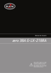
LINE DRAWINGS
1350
These units are manufactured using 15/18 mm
Finnish Birch plywood. The aero 50 enclosure
shape is trapezoidal with 5º angles. The LX-218C
and LX-218CR enclosures are rectangular. The aero
50 system incorporates captive rigging hardware
which is compatible with one another and
designed to provide a fast, simple and safe rigging
by means of quick release safety pins. Splay
angles can be changed from 0º to 3.2º in 0.8º
increments and from 3.2º to 9.6º in 1.6º
increments.
475
592
627
The D.A.S. Audio æro series2 offers units for
applications requiring precise control of the vertical
coverage and high sound pressure levels. The aero
50 is an externally powered, three-way, high
efficiency line array module which integrates two
15” low frequency units with 4” voice coils, four 8”
mid-range devices which utilize 2.5” voice coils
and two compression drivers with 3” coils and 1.5”
exit geometry in a single unit. The compression
drivers are coupled to two Serpis high frequency
plane wave adaptors insuring coherent high
frequency summing and the generation of a flat,
isophasic wave front. When increased sound
pressure level in the low frequency range is
required, the system can be used in conjunction
with the LX-218C (stacking) or the LX-218CR
(rigging), subwoofer units (LX series manual for more
information).
These systems are ideal for applications such
as large-scale outdoor/indoor events in arenas,
stadiums or theaters. Use of the DSP-4080 digital
processor is recommended for the æro series2
systems. Not using the DSP-4080 digital processor
with the aero 50 will adversely affect the sound
quality and may damage system components.
aero 50
ALL DIMENSIONS IN MILIMETERS
To facilitate transport, the aero 50 units are
equipped with a PL-50 front dolly panel attached
by means of the rigging hardware. The front dolly
panel is useful when rigging systems. The LX218CR units can be moved by way of the PLLX218C front dolly panel attached by means of the
rigging hardware or by way of the PL-218CS, a dolly
for vertically stacking (up to 3 units). The LX-218C
units can be moved by way of the PL-218CS. Also
an accessory, KITW-100 (caster kit), is available.
The loudspeakers used in the system feature
advanced technologies; new TAF (total air flow)
cooling systems, Neodymium magnetic circuits
which allow for important weight reductions,
titanium diaphragms for the high frequency
sections,
and
low-mid
frequency
cones
manufactured using crossed fibers and elastic
suspension that provide exceptional stability in the
vertical plane.
The model aero 50 includes two 15GNR, 15”
cone transducer with 4” EFW voice coils and
Neodymium magnet assemblies in a bass-reflex
configuration.
Manual del Usuario / aero 50 / User’s Manual
3
RIGGING SYSTEM
Warning
This manual contains needed information for
flying DAS Audio line array systems, description of
the elements and safety precautions. To perform
any operations related to flying the system, read
the present document first, and act on the
warnings and advice given. The goal is to allow the
user to become familiar with the mechanical
elements required to fly the acoustic system, as
well as the safety measures to be taken during
set-up and teardown.
Only experienced installers with adequate
knowledge of the equipment and local safety
regulations should fly speaker boxes. It is the
user's responsibility to ensure that the systems to
be flown (including flying accessories) comply with
state and local regulations.
The working load limits in this manual are the
results of tests by independent laboratories. It is
the user's responsibility to stay within safe limits. It
is the user's responsibility to follow and comply
with safety factors, resistance values, periodical
supervisions and warnings given in this manual.
Product improvement by means of research and
development is ongoing at DAS Audio,
specifications are subject to change without
notice.
To this date, there is no international standard
regarding the flying of acoustic systems. However,
it is common practice to apply 5:1 safety factors
for enclosures and static elements. For slings and
elements exposed to material fatigue due to
friction and load variation the following ratios must
be met; 5:1 for steel cable slings, 4:1 for steel
chain slings and 7:1 polyester slings. Thus, an
element with a breaking load limit of 1000 kg may
be statically loaded with 200 kg (5:1 safety factor)
and dynamically loaded with 250 Kg (4:1 safety
factor).
Absolutely no risks should be taken with
regards to public safety. When flying enclosures
from ceiling support structures, extreme care
should be taken to assure the load bearing
capabilities of the structures so that the installation
is absolutely safe. Do not fly enclosures from
unsafe structures. Consult a certified professional if
needed. All flying accessories that are not supplied
by DAS Audio are the user's responsibility. Use at
your own risk.
Description
DAS Audio aero 50 and LX-218CR, line array
systems, include 2 rigging structures on each side
of the box. Manufactured from zinc plated steel
they are painted black and are affixed to an
internal plate with special crop resistant screws.
Two special stainless steel guides are assembled
to each of the structures: G1A50 (front guide) and
G2A48 (back guide), allow for stacking or flying of
boxes. Splay angles can be changed from 0º to
3.2º in 0.8º increments and from 3.2º to 9.6º in
1.6º increments. To lock both guides, six (6) quick
release safety pins (supplied) must be used.
The G1A50 front guide provides a solid
connection to the box and whatever is on top of it,
while the G2A48 rear guide determines the vertical
splay angle (whether stacked or flown), as a
function of the hole where the pin gets inserted.
When flying a system, the working load must
be lower than the resistance of each individual
flying point in the enclosure, as well as each box.
Rigging hardware should be regularly inspected
and suspect units replaced if in doubt. This is
important to avoid injury and absolutely no risks
should be taken in this respect. It is highly
recommended that you implement an inspection
and maintenance program on flying elements,
including reports to be filled out by the personnel
that will carry out the inspections. Local
regulations may exist that, in case of accident,
may require you to present evidence of inspection
reports and corrective actions after defects were
found.
4
Manual del Usuario / aero 50 / User’s Manual
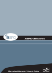
A) AX-AERO50
G2A48
QUICK RELEASE PIN 8X30
(6 UNITS PER BOX)
G1A50
To aid the setting of the G2A48 guide in the
corresponding hole in the top box, each hole is
labeled with an associated angle, both for stacked
and flown applications. To fit the guides into the
holes, highly resistant 8 mm quick release pins
with a ball safety lock are used.
FLY
The structure will be attached to the first enclosure
of the array by means of the guides G1A50,
G2A48, and six quick release safety pins.
STACK
9.6º
9.6º
The AX-AERO50 rigging structure is made up of
a central pick-up bar made of steel and two
dismountable lateral panels that are attached to
the pick-up bar by way of steel safety pins. There
is an intermediate reinforcement which is used to
attach the lifting cables. The position of the safety
pins will determine the angle of the array (see the
positions marked on the AX-AERO50).
Weight: 51 kg {112.2 lb}
Dimensions (Al x An x Pr): 342 x 1440 x 721 (mm.)
{H x W x D: 13.5” x 56.7” x 28.4”}
WLL: 1700 kgf
8º
8º
6.4º
6.4º
4.8º
4.8º
3.2º
3.2º
2.4º
1.6º
FLY
STACK
9.6º
9.6º
8º
0.8º
1.6º
0º
6.4º
8º
6.4º
4.8º
4.8º
3.2º
3.2º
2.4º
1.6º
B) Chain hoists
0.8º
1.6º
0º
0.8º
0º
0.8º
0º
For flying boxes and defining the splay angle,
the pins must be inserted in the slot of G2A48,
whereas for stacking (stacked), the pin goes
through the top hole of the guide.
All units in a column will be flown from the AXAERO50 rigging structure (bumper bar), which
should be used with one hoist. The hoist should
have an adequate load capacity. In case of flying
12 units or more, two hoists and two pick up bars
will be needed.
C) Platform PL-50
The PL-50 dolly panels facilitate transport of the
aero 50 systems. They can also be used to
facilitate flying the systems. Each cover is attached
to the enclosure by using the flying hardware
attached to each box and is fixed with the quick
release safety pins.
APILAR
(STACK)
COLGAR
(FLY)
All of the elements needed to rig or stack the
systems are integral to the enclosure (G1A50,
G2A48 and the quick release safety pins). The
additional items needed are the AX-AERO50 rigging
structure (bumper bar), chains and hoists, the PL50 dolly platforms and the AX-COMBO12 rigging
adapter.
Manual del Usuario / aero 50 / User’s Manual
5
D) AX-COMBO12
Safety factors
The AX-COMBO12 is a rigging adapter to be
used when aero 12A units are needed to be flown
under aero 50 units as dowfill systems. Maximum 6
aero 12A units can be flown from this rigging grid.
The AX-COMBO12 includes front and rear steel
guides which permit variation of the angle between
it and the last aero 50 cabinet in the cluster. Angles
vary from 1.8º to 9.6º.
The safety factor is defined as the coefficient
between the breaking load limit and the maximum
safe working load limit (SWLL). In this case, the
breaking load limit of each of the flying points is
4,000 kg (8,820 lbs) as determined by destructive
testing in independent laboratories. With a 10:1
safety factor, a total amount of 1,600 kg (3,527
lbs) can be flown from the 4 flying points. Each
flying point has a capacity of 400 kg (882 lbs) with
a 10:1 safety factor.
4 x 400kg
Weight: 19.6 kg {43 lb}
Dimensions (Al x An x Pr): 72 x 1350 x 580
(mm.) {H x W x D: 2.8” x 53” x 22.8”}
WLL: 170 kgf
The AX-COMBO12 is joined to the last aero 50
cabinet using G1A50 and G2A48 included steel
guides and 6 quick release pins. The angle
depends on the hole of the rigging structures
where the pins are inserted, through the slots of
G2A48. The first aero 12A unit is joined to the AXCOMBO12 using its G1A and G2A included steel
guides and quick release pins.
6
The maximum number of units that can be
suspended from the AX-AERO50 flying grid is 16.
The maximum limits established by the
manufacturer should never be exceeded.
The use of two hoists with a load capacity as
expressed on the previous page is mandatory. It
should be kept in mind that at certain moments,
the complete load may be supported by only one
of the hoists. This is why the load capacity of the
individual hoist must be superior to the weight of
the array column.
Manual del Usuario / aero 50 / User’s Manual
ASSEMBLING AN ARRAY
Transporting the cabinets
To facilitate transport, the aero 50 units are
equipped with a PL-50 front dolly panel attached
by means of the rigging hardware. The front dolly
panel is useful when rigging systems. The LX218CR units can be moved by way of the PLLX218C front dolly panel attached by means of the
rigging hardware or by way of the PL-218CS, a dolly
for vertically stacking (up to 3 units). The LX-218C
units can be moved by way of the PL-218CS. Also
an accessory, KITW-100 (caster kit), is available (LX
series manual for more information).
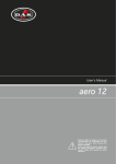
Once this is accomplished, the AX-AERO50
structure is set in it's vertical position, taking into
consideration the position of the safety pins. Using
the Ease Focus simulation software will provide the
points that should be used for the required angle
(see ‘1’ and ‘2’ below).
The next step is to attach the first unit to the
AX-AERO50 by introducing the G1A50 and G2A48
guides in the receiving points of the rigging
structure and assuring them with the six safety
pins. The safety pins should be inserted in the slot
of the G2A48. It is very important to make sure
that the pins have been inserted and locked
correctly.
Planning/inspection
Before installing the system it is a good idea to
run a simulation with the Ease Focus program
utilizing the venue dimensions. This way we can
determine the needs that should be met by the
rigging structures such as hoists, cranes, beams,
rigging points, etc. Besides providing weight
information, the program also provides users with
splay angle information, safety pin positions and
coverage predictions.
17
16
15
14
13
12
11
6
8
8
10
10
12
11
14
12
15
14
17
15
18
REAR
Inspection is the next step after planning and
acquiring all the necessary parts needed to elevate
the systems. All parts, including the hardware
attached to the enclosure, the safety pins, etc.
should be thoroughly inspected before each use.
Units exhibiting deformations, cracks or any other
defect should be replaced with new units.
9
8
7
6
5
4
3
2
1
16
20
16
20
16
20
16
20
16
20
16
20
16
20
15
19
14
17
13
16
LX
æro
FRONT
2
4
6
5
It is extremely important to assure that each
and every one of the aforementioned structures is
capable of supporting a superior load than that of
the complete system.
10
MAX. NUMBER OF UNITS ALLOWED
1
3
Once the first unit of the array has been
attached to the AX-AERO50, the assembly should
be lifted by way of the hoist until the wheels of the
PL-50 dolly platform lift off the ground. From this
point on, the hoist can be used to lift the box into
a horizontal position.
It is important to establish an inspection routine
for the complete rigging system before each event
or installation as well as establishing the maximum
load specifications of the hoists to be used.
Rigging should be carried out by experts
familiar with the way the systems function and
their characteristics.
On occasions, it may be convenient to have
additional tie down points to impede the array
from twisting or swinging.
Assembling an array “one by one”
When few units are to be used (minimum
systems recommended is 6 units) or when the
dolly platforms cannot be used due to a lack of
space, the enclosures will have to be hung “one by
one”. The first step will to attach the AX-AERO50
grid structure to the hoists. The chain slings need
to be attached to the structure using the shackles
provided with the grid.
Manual del Usuario / aero 50 / User’s Manual
7
Once the first box has been placed at 0º
and raised approximately 75cm (30 in) the second
box of the array can be placed nearby. Once
located in position, the G2A48 guides of the
second box should be freed and inserted in the
rear located receiving points of the suspended box
and secured with the safety pins.
Once the splay angle between the first
two boxes has been determined, the front of the
box can be lifted into place. Three people will be
needed to undertake this operation, two to lift the
box and one to fit the G1A50 guide and safety
pins into the upper box.
8
Manual del Usuario / aero 50 / User’s Manual
Once the boxes have been joined, the front dolly panels can be removed. The next boxes should be
attached “one by one” using the methods described. Finally, the array should be hoisted to the correct height
and secured with slings to avoid swinging.
This method is more time consuming than assembling an array by the “all at once” procedure, but is
appropriate for situations due to a lack of space in which to array the system. During the process, the safety
pins should be checked making sure they are secured correctly. Once the complete array has been lifted into
place, additional slings should be attached to secure the array and avoid swinging.
Assembling an array using the PL-50 platform
The PL-50 platform can be used to easily
transport aero 50 units to the assembling area. To
use this method of assembling and hoisting the
array, there must be enough space to permit
linking all the boxes from the front of the rigging
hardware.
The first step will be to attach the AX-AERO50
grid and the hoist (or hoists). Once this has been
accomplished, the rigging structure can be placed
in a vertical position by lifting the rear hoist and
lowering the front hoist so that the rear of the grid
is on top and the front of the grid at the bottom,
ready to receive the first box.
17
16
15
14
13
12
11
6
8
8
10
10
12
11
14
12
15
14
17
15
18
10
9
8
7
6
5
4
3
2
1
16
20
16
20
16
20
16
20
16
20
16
20
16
20
15
19
14
17
13
16
LX
æro
MAX. NUMBER OF UNITS ALLOWED
REAR
FRONT
2
4
6
5
1
3
The next step is to attach the first unit to the
grid by introducing the G1A50 and G2A48 guides
in the receiving points of the grid structure and
assuring them with the (6) safety pins. The safety
pins should be inserted in the slot of the G2A48. It
is very important to make sure that the pins have
been inserted and locked correctly.
Once the first box is attached to the structure, the remaining boxes should be brought to the array and
attached repeating the previous steps (1 and 2) using G1A50 guides and safety pins per side making sure
that the pins have been inserted and locked correctly.
1
2
Proceed to attach the remaining units in the same manner until all the array units are attached to one
another. For example, if we are assembling a six unit array, the process will be repeated six times. When all
the units are attached, the complete array is ready to be hoisted.
Manual del Usuario / aero 50 / User’s Manual
9
The complete assembly should begin being lifted from the hoist (3) so that the rear of the enclosures
come together due to their trapezoidal shape. The hoist will be used only to take up slack in the chain, all the
weight should be on the hoist. Proceed in this manner until the wheels of the last enclosure are off the
ground. From here on, the array can now be lifted with the hoist.
3
4
5
When the rear of the enclosures come together, the G2A48 rear guides should be positioned (4) into the
hardware of the box above, inserting (5) the safety pins in the correct angle position. Since the boxes are
flown, the safety pins should be in the slot of the G2A48 guide.
As the array assembly is lifted (6 & 7), the PL-50 platforms should be removed.
10
Manual del Usuario / aero 50 / User’s Manual
6
7
Once the complete array has been lifted into place, additional slings should be attached to secure the
array and avoid swinging.
To lower the system, both hoists should be used until the lowest box is about 1 meter from the ground.
From there on, only the front hoist should be used so that the array assembly begins to lean forward, at the
same time, the PL-50 platforms should be reattached. When the wheels of the lowest enclosure are firmly on
the ground, the array assembly can now be lowered using the rear hoist.
While the array assembly descends, the rear of the enclosures will come together, at that moment, the
safety pins which hold the G2A48 guides in place should be removed. Once removed, the guides should be
swung back into the box they belong to. Finally, the boxes should be totally detached from one another by
releasing the G1A50 guide.
Manual del Usuario / aero 50 / User’s Manual
11
CONFIGURATIONS
12
Manual del Usuario / aero 50 / User’s Manual
Manual del Usuario / aero 50 / User’s Manual
13
14
Manual del Usuario / aero 50 / User’s Manual
Manual del Usuario / aero 50 / User’s Manual
15
16
Manual del Usuario / aero 50 / User’s Manual
aero 50
Manual del Usuario / aero 50 / User’s Manual
Birch Plywood
Black Paint
Integrated in box design
2 x NL8 wired as LF1±1, LF2±2,
MF±3, HF±4
47.5 x 135 x 62.7 cm
(18.7 x 53.1 x 24.7 in)
85 kg (187 lbs)
AX-aero50 Bumper
Ax-Combo12 Rigging Adapter
PL-50 Dolly Panel (included)
Enclosure Material
Color/Finish
Rigging System
Connectors
Dimensions (H x W x D)
LX-218C
55 x 128 x 63.2 cm
(22 x 51 x 24.9 in)
78.5 kg (176.1 lbs)
AX-aero50 Bumper
Pick Up Bar for AX-aero50 Bumper
AX-Combo12 Rigging Adapter
KITW-100 Caster kit
KITR-LX218C Rigging hardware kit
PL-LX218C Dolly Panel
PL-218CS Flat Bed Dolly
Birch Plywood
Black Paint
--2 x NL8 wired ±1
Rectangular
2 x 2400 W @ 4 ohms
( 2 units LX-218C)
4 ohms
2 18LX/GM 18LX
142 dB
103 dB SPL
28 Hz – 100 Hz
----2000 W
(1).-Based on a 2 hour test continuously applying 6 dB crest factor pink noise (IEC shaped).
(2).-Maximum calculated Peak SPL based on sensitivity and RMS power handling.
Weight
Accessories
Trapezoidal 5º
45 Hz – 20 kHz
90º Nominal
Splay Angle Dependent
LF: 2 x 700 W, MF: 700W,
HF: 300W
LF: 99 dB SPL, MF: 104 dB SPL,
HF: 112dB SPL
LF: 136 dB, MF: 139 dB,
HF: 141 dB
LF: 2 x 15GNR/GM 15G
MF: 4 x 8MN/GM 8MN
HF: 2 x M-75N/GM M-75N
LF: 8+8ohms, MF: 8ohms,
HF:16 ohms
4 amps 2 x 1400 @ 4 ohms
( 4 units aero 50)
Enclosure Geometry
Recommended Amplifier Power
Nominal Impedance
Transducers/Replacement Parts
Rated Maximum Peak SPL at 1 m
(2)
On-Axis Sensitivity 1 W / 1 m
Model
Frequency Range (-10 dB)
Horizontal Coverage (-6dB)
Vertical Coverage
(1)
RMS (Average) Power Handling
LX-218CR
55 x 135 x 69.6 cm
(22 x 54 x 27.4 in)
94.5 kg (207.9 lbs)
AX-aero50 Bumper
Pick Up Bar for AX-aero50 Bumper
AX-Combo12 Rigging Adapter
KITW-100 Caster kit
PL-LX218C Dolly Panel (included)
PL-218CS Flat Bed Dolly
Birch Plywood
Black Paint
Integrated in box design
2 x NL8 wired ±1
Rectangular
2 x 2400 W @ 4 ohms
( 2 units LX-218C)
4 ohms
2 18LX/GM 18LX
142 dB
103 dB SPL
28 Hz – 100 Hz
----2000 W
SPECIFICATIONS
17
UM_AE50_02_EN
www.dasaudio.com
D.A.S. AUDIO, S.A.
C/. Islas Baleares, 24
46988 Fuente del Jarro
Valencia, SPAIN
Tel. 96 134 0525
Tel. Intl. +34 96 134 0860
Fax 96 134 0607
Fax Intl. +34 96 134 0607
D.A.S. AUDIO OF AMERICA, INC.
Sunset Palmetto Park
6816 NW 77th Court.
Miami, FL. 33166 - U.S.A.
TOLL FREE: 1-888DAS4USA
Tel. +1 305 436 0521
Fax +1 305 436 0528
D.A.S. AUDIO ASIA PTE. LTD.
25 Kaki Bukit Crescent #01-00/02-00
Kaki Bukit Techpark 1
Singapore 416256
Tel. +65 6742 0151
Fax +65 6742 0157