1
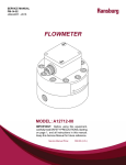
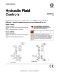
Ransburg SERVICE MANUAL AU-81-07.2 (replaces AU-81-07.1) September - 2013 FLOW REGULATOR MODELS: 70171 IMPORTANT: Before using this equipment, carefully read SAFETY PRECAUTIONS, starting on page 1, and all instructions in this manual. Keep this Service Manual for future reference. Service Manual Price: €15.00 (Euro) $20.00 (U.S.) Ransburg Flow Regulator - Contents CONTENTS PAGE SAFETY: 1-5 SAFETY PRECAUTIONS........................................................................................................... 1 HAZARDS/SAFEGUARDS......................................................................................................... 2-5 INTRODUCTION: 6-7 REGULATOR INSTALLATION................................................................................................... 6 SPECIFICATIONS....................................................................................................................... 6 FLOW REGULATORS................................................................................................................ 7 INSTALLATION: 8-10 REGULAR INSTALLATION........................................................................................................ 8 TYPICAL INSTALLATION........................................................................................................... 9 OPERATION: 11-12 OPERATION AND MAINTENANCE.......................................................................................... 11-12 PARTS IDENTIFICATION: 13-15 EXPLODED VIEW...................................................................................................................... 13-14 FLOW REGULATOR PARTS LIST............................................................................................. 15 WARRANTY POLICIES: 16 LIMITED WARRANTY................................................................................................................. 16 AU-81-07.2 Ransburg Flow Regulator - Safety SAFETY SAFETY PRECAUTIONS Before operating, maintaining or servicing any Ransburg electrostatic coating system, read and understand all of the technical and safety literature for your Ransburg products. This manual contains information that is important for you to know and understand. This information relates to USER SAFETY and PREVENTING EQUIPMENT PROBLEMS. To help you recognize this information, we use the following symbols. Please pay particular attention to these sections. A WARNING! states information to alert you to a situation that might cause serious injury if instructions are not followed. A CAUTION! states information that tells how to prevent damage to equipment or how to avoid a situation that might cause minor injury. A NOTE is information relevant to the procedure in progress. While this manual lists standard specifications and service procedures, some minor deviations may be found between this literature and your equipment. Differences in local codes and plant requirements, material delivery requirements, etc., make such variations inevitable. Compare this manual with your system installation drawings and appropriate Ransburg equipment manuals to reconcile such differences. ! WARNING The user MUST read and be familiar with the Safety Section in this manual and the Ransburg safety literature therein identified. This manual MUST be read and thoroughly understood by ALL personnel who operate, clean or maintain this equipment! Special care should be taken to ensure that the WARNINGS and safety requirements for operating and servicing the equipment are followed. The user should be aware of and adhere to ALL local building and fire codes and ordinances as well as NFPA-33 SAFETY STANDARD, LATEST EDITION, prior to installing, operating, and/or servicing this equipment. ! WARNING The hazards shown on the following pages may occur during the normal use of this equipment. Please read the hazard chart beginning on page 2. Careful study and continued use of this manual will provide a better understanding of the equipment and process, resulting in more efficient operation, longer trouble-free service and faster, easier troubleshooting. If you do not have the manuals and safety literature for your Ransburg system, contact your local Ransburg representative or Ransburg. 1 AU-81-07.2 Ransburg Flow Regulator - Safety AREA HAZARD Spray Area Fire Hazard Tells where hazards may occur. Tells what the hazard is. Improper or inadequate operation and maintenance procedures will cause a fire hazard. Protection against inadvertent arcing that is capable of causing fire or explosion is lost if any safety interlocks are disabled during operation. Frequent Power Supply or Controller shutdown indicates a problem in the system requiring correction. SAFEGUARDS Tells how to avoid the hazard. Fire extinguishing equipment must be present in the spray area and tested periodically. Spray areas must be kept clean to prevent the accumulation of combustible residues. Smoking must never be allowed in the spray area. The high voltage supplied to the atomizer must be turned off prior to cleaning, flushing or maintenance. When using solvents for cleaning: •• Those used for equipment flushing should have flash points equal to or higher than those of the coating material. •• Those used for general cleaning must have flash points above 100°F (37.8°C). Spray booth ventilation must be kept at the rates required by NFPA-33, OSHA, country, and local codes. In addition, ventilation must be maintained during cleaning operations using flammable or combustible solvents. Electrostatic arcing must be prevented. Safe sparking distance must be maintained between the parts being coated and the applicator. A distance of 1 inch for every 10KV of output voltage is required at all times. Test only in areas free of combustible material. Testing may require high voltage to be on, but only as instructed. Non-factory replacement parts or unauthorized equipment modifications may cause fire or injury. If used, the key switch bypass is intended for use only during setup operations. Production should never be done with safety interlocks disabled. Never use equipment intended for use in waterborne installations to spray solvent based materials. The paint process and equipment should be set up and operated in accordance with NFPA33, NEC, OSHA, local, country, and European Health and Safety Norms. AU-81-07.2 2 Ransburg Flow Regulator - Safety AREA Tells where hazards may occur. Spray Area HAZARD Tells what the hazard is. SAFEGUARDS Tells how to avoid the hazard. Explosion Hazard Improper or inadequate operation and maintenance procedures will cause a fire hazard. Protection against inadvertent arcing that is capable of causing fire or explosion is lost if any safety interlocks are disabled during operation. Frequent Power Supply or Controller shutdown indicates a problem in the system requiring correction. Electrostatic arcing must be prevented. Safe sparking distance must be maintained between the parts being coated and the applicator. A distance of 1 inch for every 10KV of output voltage is required at all times. Unless specifically approved for use in hazardous locations, all electrical equipment must be located outside Class I or II, Division 1 or 2 hazardous areas, in accordance with NFPA-33. Test only in areas free of flammable or combustible materials. The current overload sensitivity (if equipped) MUST be set as described in the corresponding section of the equipment manual. Protection against inadvertent arcing that is capable of causing fire or explosion is lost if the current overload sensitivity is not properly set. Frequent power supply shutdown indicates a problem in the system which requires correction. Always turn the control panel power off prior to flushing, cleaning, or working on spray system equipment. Before turning high voltage on, make sure no objects are within the safe sparking distance. Ensure that the control panel is interlocked with the ventilation system and conveyor in accordance with NFPA-33, EN 50176. Have fire extinguishing equipment readily available and tested periodically. General Use and Maintenance Improper operation or maintenance may create a hazard. Personnel must be given training in accordance with the requirements of NFPA-33, EN 60079-0. Personnel must be properly trained in the use of this equipment. Instructions and safety precautions must be read and understood prior to using this equipment. Comply with appropriate local, state, and national codes governing ventilation, fire protection, operation maintenance, and housekeeping. Reference OSHA, NFPA-33, EN Norms and your insurance company requirements. 3 AU-81-07.2 Ransburg AREA Tells where hazards may occur. Spray Area / High Voltage Equipment Flow Regulator - Safety HAZARD Tells what the hazard is. SAFEGUARDS Tells how to avoid the hazard. Electrical Discharge There is a high voltage device that can induce an electrical charge on ungrounded objects which is capable of igniting coating materials. Inadequate grounding will cause a spark hazard. A spark can ignite many coating materials and cause a fire or explosion. Parts being sprayed and operators in the spray area must be properly grounded. Parts being sprayed must be supported on conveyors or hangers that are properly grounded. The resistance between the part and earth ground must not exceed 1 meg ohm. (Refer to NFPA-33.) Operators must be grounded. Rubber soled insulating shoes should not be worn. Grounding straps on wrists or legs may be used to assure adequate ground contact. Operators must not be wearing or carrying any ungrounded metal objects. When using an electrostatic handgun, operators must assure contact with the handle of the applicator via conductive gloves or gloves with the palm section cut out. NOTE: REFER TO NFPA-33 OR SPECIFIC COUNTRY SAFETY CODES REGARDING PROPER OPERATOR GROUNDING. All electrically conductive objects in the spray area, with the exception of those objects required by the process to be at high voltage, must be grounded. Grounded conductive flooring must be provided in the spray area. Always turn off the power supply prior to flushing, cleaning, or working on spray system equipment. Unless specifically approved for use in hazardous locations, all electrical equipment must be located outside Class I or II, Division 1 or 2 hazardous areas, in accordance with NFPA-33. AU-81-07.2 4 Ransburg Flow Regulator - Safety AREA Tells where hazards may occur. Electrical Equipment HAZARD Tells what the hazard is. Tells how to avoid the hazard. Electrical Discharge An electrical arc can ignite coating materials and cause a fire or explosion. Unless specifically approved for use in hazardous locations, the power supply, control cabinet, and all other electrical equipment must be located outside Class I or II, Division 1 and 2 hazardous areas in accordance with NFPA-33 and EN 50176. Turn the power supply OFF before working on the equipment. Test only in areas free of flammable or combustible material. Testing may require high voltage to be on, but only as instructed. Production should never be done with the safety circuits disabled. Before turning the high voltage on, make sure no objects are within the sparking distance. Certain material may be harmful if inhaled, or if there is contact with the skin. Follow the requirements of the Material Safety Data Sheet supplied by coating material manufacturer. High voltage equipment is utilized in the process. Arcing in the vicinity of flammable or combustible materials may occur. Personnel are exposed to high voltage during operation and maintenance. Protection against inadvertent arcing that may cause a fire or explosion is lost if safety circuits are disabled during operation. Frequent power supply shutdown indicates a problem in the system which requires correction. Toxic Substances SAFEGUARDS Adequate exhaust must be provided to keep the air free of accumulations of toxic materials. Use a mask or respirator whenever there is a chance of inhaling sprayed materials. The mask must be compatible with the material being sprayed and its concentration. Equipment must be as prescribed by an industrial hygienist or safety expert, and be NIOSH approved. Spray Area Explosion Hazard – Incompatible Materials Halogenated hydrocarbon solvents for example: methylene chloride and 1,1,1,-Trichloroethane are not chemically compatible with the aluminum that might be used in many system components. The chemical reaction caused by these solvents reacting with aluminum can become violent and lead to an equipment explosion. 5 Aluminum is widely used in other spray application equipment - such as material pumps, regulators, triggering valves, etc. Halogenated hydrocarbon solvents must never be used with aluminum equipment during spraying, flushing, or cleaning. Read the label or data sheet for the material you intend to spray. If in doubt as to whether or not a coating or cleaning material is compatible, contact your coating supplier. Any other type of solvent may be used with aluminum equipment. AU-81-07.2 Ransburg Flow Regulator - Introduction INTRODUCTION GENERAL DESCRIPTION SPECIFICATIONS The Ransburg Flow Regulator is an air-operated unit that may be used with any suitable paint circulating system or pressure pot to provide a regulated flow of coating material for reciprocating electrostatic equipment. The regulator uses a stainless steel diaphragm that balances signal air pressure against the output fluid pressure. Environmental / Physical Fluid delivery can be varied from about 20 to 800 cc per minute by using one of four available orifice assemblies (or an appropriate Ransburg fluid valve as an adjustable orifice) and adjusting the signal air pressure. This Flow Regulator is most useful with reciprocating spray systems because it is highly sensitive to very small changes in input head pressure and has a very fast response to such variations. Since signal air pressure is set remotely at a control panel, fluid delivery may be adjusted as desired while the reciprocator is in motion. The regulator is available with either circulating or non-circulating input end-fittings and either a standard or insulated mounting. An opening is provided for straight-through flushing. AU-81-07.2 Diameter: 4-1/8-inches Height: 5.5-inches maximum (w/plug and orifice) Width: 5.0-inches (input fitting to signal air adjustment screw) Weight: 70171 - 2 lbs. 9 oz. (w/plug and orifice assy.) Connections: Flushing Inlet - 1/4” NPT Paint Outlet - 1/4” NPT Signal Air - 1/4” NPT Paint Inlet - 1/4” NPT (Except recirculating system end fitting 1/2” NPT) Max Paint Inlet Pressure: 40 psig Max Paint Pilot Pressure: 30 psig Max Fluid Flowrate Multiple Applicators: 1800 cc/min Recommended Differential Pressure (Paint Inlet - Pilot Air): 10 psig 6 Ransburg Flow Regulator - Introduction Model 70171 Assembly Figure 1: Flow Regulators 7 AU-81-07.2 Ransburg Flow Regulator - Installation INSTALLATION REGULATOR INSTALLATION This information is intended ONLY to indicate the general installation parameters of this product and, where applicable, its working relationship to other Ransburg system components in typical use. Each installation is unique and should be directed by an Ransburg representative or made from the Ransburg installation drawings provided for your particular installation. Automatic Applicators Depending on the application, any of four Flow Regulator arrangements may be used. A typical installation arrangement for using the regulator with equipment is shown in Figure 2. If a circulating fluid system is being used, the modulating valve in the return side of the system must be capable of being set so that a paint pressure of 40 psi can be otbtained at the regulator. Fluid Flow Chart Turbo Disk Applicators This procedure is applicable both with and without orifice assembly and can be used with both normal and conductive paints. A typical installation arrangement for the regulator is shown in Figure 2. The unit should be mounted on the insulator support with the output port facing down. The orifice, if used, should be installed in the regulator, using the size that will provide the requried fluid delivery. (See “Flow Characteristics Chart” in this section.) If the paint pump or pressure pot is located at some distance from the applicator equipment and/or if a recirculating system is used, it is often desirable to install a pressure gauge at some convenient point in the paint line close to the regulator. This gauge will permit quick comparison of paint fluid pressure (close to the regulator) with the signal air pressure at the control panel. AU-81-07.2 8 Ransburg Flow Regulator - Installation Figure 2: Typical Installation NOTES: 1. Use “A” if paint hose is less than 20 ft. long. 2. Use “B” if delivery is greater than 400 cc/min and paint hose is 20 to 35 ft. long. 3. Paint pressure at regulating valve must be greater than control. 4. If conducting type paint is used, paint supply must be insulated (5875-00 insulated stand for tank). 9 AU-81-07.2 Ransburg Adjustment Procedures 1. When several regulators are being used in a paint system, an adjustment screw on the signal air side of the units can be used to balance signal air and fluid delivery variations between units in order to secure uniform delivery from all the regulators. Flow Regulator - Installation The final fluid output pressure and volume is achieved by adjusting the fluid valve to the desired amount. Major adjustments in output pressure and volume to accomodate a large change in viscosity may require an adjustmnet at the fluid valve and/or of paint input pressure. Adjustment Procedures 2. The paint input pressure must always be higher than the signal air pressure, preferably by 10 psi higher than maximum signal pressure. The normal signal pressure range is 0 to 30 psi. 1.Select a paint inlet pressue and a signal air pressure for the flow regulator (40 psi inlet pressure with a 15 psi signal air pressure is a good range). 3. Paint lines, flow regulator, orifice assemblies, filter screens, and nozzles must be kept clean and open. Plugging will alter the regulated flow of the coating material. 2. With the air signal to the fluid valve OFF, close the needle adjusting screw at the top of the valve by turning clockwise until resistance is met, then open the valve by turning the adjusting screw 50% open (approximately three full turns). 4. Input paint pressure variations have little or no effect on the paint output through the regulator, provided. a. The paint pressure always remains higher than the signal air pressure, and b. The output (as signaled) is within the flow capacity of the regulator. 5.Minor changes in paint viscosities have only minor effects on output flow curves. Installation Parameters Paint input pressure should be 10 psi higher than the maximum signal air pressure. A good typical working range for normal solvent base paints is 40 psi of paint input pressure with the signal air pressure ranging from 0 to a maximum of 30 psi depending on the desired delivery. Paint pressure may be reduced if 40 psi is not needed for the flow requirement. However, if the paint pressure is reduced, the signal air pressure should also be reduced proportionately to maintain a differential between the signal air and paint pressures of at least 10 psi. AU-81-07.2 3. Take a fluid delivery at the atomizer. NOTE If a reciprocator is used, take a fluid delivery at the atomizer at the bottom of the reciprocator stroke and at the top of the reciprocator stroke. Compare these deliveries. If they are approximately equal, then go on to the next step. If they are not equal, raise the input fluid pressure to the flow regulator and turn the adjusting knob on the fluid valve one half turn clockwise. Continue this process until the deliveries are equal at the top and bottom of the reciprocator stroke. > 4. Record all fluid flow information. This information provides the user with a means of charting the air pressures required to obtain a certain fluid delivery. Recorded information also aids in production repeatability. 5. Future adjustments in delivery can be made by adjusting fluid inlet pressure at the flow regulator or the adjusting screw on the fluid valve depending on the amount of change in fluid volume or viscosity. 10 Ransburg Flow Regulator - Operation OPERATION OPERATION AND MAINTENANCE These instructions indicate the general operating and maintenance parameters for this product in a normal working relationship with other Ransburg System components in typical use. Each user application is unique and operation should be initited under the guidance of an Ransburg representative and/or be based on carefully conducted tests and on careful observation of the initial production characteristics. Tools required: 3/8” open end wrench 7/16” open end wrench 9/16” open end wrench Needle nose pliers Large screw driver (5/8” diameter bit X 1/16” thick) Once installed and adjusted, the operation of this product is automatic with the system controller. If a change in equipment or coating material or method requires a change in operating parameters, see the “Installation” section for “Adjustment Procedures”. Refer to Figure 3 to identify the components and proceed as follows: Housekeeping • Flush the regulator with solvent. The Ransburg Flow Regulator is simple, rugged, and reliable, It eliminates flow variations through reciprocated equipment due to changes in pressure and is capable of providing long and reliable service. However, it is imperative to keep dirt particles and paint deposits from building up at orifices or orifice screen filters. Such deposits reduce fluid output and make it impossible to get repeatable results with the same operating parameters. Orifice screens. should be removed and thoroughly cleaned as often as the paint formulation and workload demand. In extreme cases, it may be desirable to add an additional suitable input filter (50-75 micron) on the upstream or input side of the regulator. Whenever the unit is shut down for an prolonged period such as a weekend or longer, the system should be thoroughly flushed and the orifice assembly screens removed and cleaned. Good maintenance is essential to safe and pro- 11 ductive operation. Schedules shold be established by the user, based on Ransburg supplied information and observation of your production requirements. You do not have to maintain all of your equipment, only those items that you want to continue to use. Disassembly To remove the regulator from the installation for service: • Release the air and fluid pressures. • Disconnect the air and fluid connections at the regulator and remove the regulator from the installation. If orifice assemblies are located externally rather than in the flow regulators, remove them at this time as well. 1. Remove plug [17] and orifice assembly [26] from the body of the regulator (if used). 2. Remove the two (2) cap screws [22] or [24] that hold the inlet fitting [21] or [23] to the flow regulator and then remove the fitting. 3. Loosen the six (6) machine screws [3] that hold the halves of the regulator body together. Separate the body assembly and remove o-ring [13], diaphragm plates [9], and diaphragm [10]. One spring [8] will also come out at this time. AU-81-07.2 Ransburg 4. Take the signal air section of the regulator body and screw lock nut [2] all the way out. Measure the length of the adjusting screw from its end to the body of the regulator and record the measurement. (On reassembly, the adjusting screw should be reset to this position.) Now tighten adjusting screw [1] completely. Upper spring button [6] with o-ring [7] may not be removed from the regulator body. Remove adjusting screw [1] and lock nut [2]. 5. Take the other half of the regulator body and remove snap ring [11] using the needle nose pliers while carefully compressing spring [8]. Remove spring retainer [12], spring [8], and needle [19]. 6. Unscrew needle seat [18] from the regulator body using a large screwdriver. 7. Remove all o-rings. The flow Regulator is now completely disassembled. Cleaning Thoroughly soak all parts that are to be reused in a suitable, clean solvent. (One compatible with the paints being used.) Then brush with a bristle brush until clean. Do NOT use a wire brush when cleaning the regulator parts. Examine needle [19] carefully for evidence of wear and replace if it is noticeably scored or worn, or if the regulator fails to shut off completely. It is recommended that needle seat [18] be replaced with a new one whenever it is removed from the assembly. All orings should be replaced with new when removed. Flow Regulator - Operation ! CAUTION > NEVER, under any circumstances, use SILICONE GREASES to lubricate parts of the flow regulator. 1. Screw needle seat [18] into the regulator body using a large screwdriver. 2. Replace needle [19], spring [8], and spring retainer [12] into the appropriate half of the regulator body. Replace snap ring [11] using the needle nose pliers while carefully compressing spring [8]. 3. Replace adjusting screw [1] and lock nut [2]. Now loosen adjusting screw [1] completely. Reinstall the signal air section of the regulator body and screw lock nut [2] all the way in. Measure the length of the adjusting screw from its end to the body of the regulator and reset it to the same measurement that was recorded during disassembly. 4. Reinstall spring [8], diaphragm [10], diaphragm plates [9], and o-ring [13]. Join the halves of the body assembly and secure the six (6) machine screws [3]. 5. Reinstall fitting [21] or [23] to the flow regulator and secure the two cap screws [22] or [24] that hold the inlet. 6. Reinstall orifice assembly [26] and plug [17] to the body of the regulator (if used). In time, the jewel orifice assembly [26] will wear. If this normal wear causes loss of control, or low-end output remains excessive, the orifice assembly should be replaced. If the orifice assembly screen is clogged, replace it. If the input pre-filter (if used) is clogged, clean or replace the filter element. Assembly • Replace all o-rings and worn or damaged parts with new. • O-rings and screw threads should be lightly coated with petroleum jelly. AU-81-07.2 12 Flow Regulator - Parts Identification Ransburg PARTS IDENTIFICATION Figure 3a: Exploded View 13 AU-81-07.2 Ransburg Flow Regulator - Parts Identification Figure 3b: Exploded View AU-81-07.2 14 Ransburg Flow Regulator - Parts Identification FLOW REGULATOR - PARTS LIST (Figures 3a and 3b) Item # 1 2 3 4 5 6 7 8 9 10 11 12 13 14 15 16 17 18 19 20 21 22 23 24 29 30 31 32 33 34 35 34 35 36 37 38 39 40 41 Part # 9897-40F 7733-31 7783-32F 7776-04 70168-00 70164-00 7554-12 13899-00 70161-00 70162-00 A10056-04 13036-00 7554-25 7554-27 70169-00 70170-00 1625-12 13694-XX 13695-00 7554-26 70167-00 7958-32C 70166-00 7958-56C 1017-00 7787-02 7884-03 7892-01 3364-01 7958-56C 3364-01 7958-56C 7734-06 19490-02 8390-23 4342-04 7596-03 70171-XX 15393/70719 or as appropriate Description Qty Screw, Adjusting Nut, Jam Screw Lockwasher Case, Spring Button, Spring, Upper O-Ring Spring Plate, Diaphragm Diaphragm Ring, Retaining Retainer, Spring O-Ring O-Ring Case, Diaphragm, Standard Case, Diaphragm, Quick Flush (Optional) Plug, Pipe Seat, Needle Needle O-Ring Fitting Screw Fitting Screw Fitting, Straight Fitting, Swivel, Straight Fitting, Elbow, Male, 90° Connector, Male Tee Bolt Tee Bolt Lockwasher Connector, Swivel, Hose Ferrule, Brass Elbow, Street, 90° Bushing Regulator, Fluid, Circulating Valve Assembly, Fluid For Assembly -- All -- All 6All 6All -- All -- All --All 2All 2 All --All -- All -- All --All --All --70171-04/14 --70171-04/14 -- All -- All --All --All --70171-00/-03 270171-01/-03 --70171-02/-04 270171-02/-04 -- All -- All --All -- All --All 2All --All 2All 4All 2 All 7 All 2All 2All -- All -- All * Must be called out separately when ordering. -XX Determined by application. See your Ransburg “Installation Drawings” or contact your Ransburg representative. 15 AU-81-07.2 Ransburg Flow Regulator - Warranty Policies WARRANTY POLICIES LIMITED WARRANTY Ransburg will replace or repair without charge any part and/or equipment that falls within the specified time (see below) because of faulty workmanship or material, provided that the equipment has been used and maintained in accordance with Ransburg's written safety and operating instructions, and has been used under normal operating conditions. Normal wear items are excluded. THE USE OF OTHER THAN RANSBURG APPROVED PARTS, VOID ALL WARRANTIES. SPARE PARTS: One hundred and eighty (180) days from date of purchase, except for rebuilt parts (any part number ending in "R") for which the warranty period is ninety (90) days. EQUIPMENT: When purchased as a complete unit, (i.e., guns, power supplies, control units, etc.), is one (1) year from date of purchase. WRAPPING THE APPLICATOR, ASSOCIATED VALVES AND TUBING, AND SUPPORTING HARDWARE IN PLASTIC, SHRINK-WRAP, OR ANY OTHER NON-APPROVED COVERING, WILL VOID THIS WARRANTY. AU-81-07.2 RANSBURG'S ONLY OBLIGATION UNDER THIS WARRANTY IS TO REPLACE PARTS THAT HAVE FAILED BECAUSE OF FAULTY WORKMANSHIP OR MATERIALS. THERE ARE NO IMPLIED WARRANTIES NOR WARRANTIES OF EITHER MERCHANTABILITY OR FITNESS FOR A PARTICULAR PURPOSE. RANSBURG ASSUMES NO LIABILITY FOR INJURY, DAMAGE TO PROPERTY OR FOR CONSEQUENTIAL DAMAGES FOR LOSS OF GOODWILL OR PRODUCTION OR INCOME, WHICH RESULT FROM USE OR MISUSE OF THE EQUIPMENT BY PURCHASER OR OTHERS. EXCLUSIONS: If, in Ransburg's opinion the warranty item in question, or other items damaged by this part was improperly installed, operated or maintained, Ransburg will assume no responsibility for repair or replacement of the item or items. The purchaser, therefore will assume all responsibility for any cost of repair or replacement and service related costs if applicable. 16 Service Manual Price: €15.00 (Euro) $20.00 (U.S.) Manufacturing 1910 North Wayne Street Angola, Indiana 46703-9100 Telephone: 260/665-8800 Fax: 260/665-8516 Technical/Service Assistance Telephone: 800/ 233-3366 Fax: 419/ 470-2071 Technical Support Representative will direct you to the appropriate telephone number for ordering Spare Parts. © 2013 Ransburg. All rights reserved. Models and specifications subject to change without notice. Form No.AU-81-07.2 Litho in U.S.A. 09/13