1
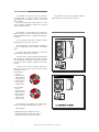
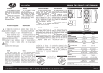
User’s Manual
VA series
Antes de utilizar el equipo, lea la sección
“Precauciones de seguridad” de este
manual. Conserve este manual para
futuras consultas.
Before operating the device, please read
the “Safety precautions” section of this
manual. Retain this manual for future
reference.
CONTENTS
SAFETY PRECAUTIONS
3
WARRANTY
4
DECLARATION OF CONFORMITY
5
INTRODUCTION
6
LINE DRAWINGS
6
SYSTEM DESCRIPTION
7
CONNECTION
8
CONFIGURATION
9
SPECIFICATIONS
10
INSTALLATION SYSTEM
11 - 14
Warning
Description
TROUBLESHOOTING
Manual del Usuario / VA series / User’s Manual
13
VA series
Precauciones de Seguridad
Safety Precautions
Cajas acústicas pasivas / Passive loudspeaker enclosures
Conserve y lea todas estas instrucciones.
Siga todas las advertencias.
El signo de exclamación dentro de un triángulo indica la
existencia de componentes internos cuyo reemplazo puede
afectar a la seguridad.
Keep these instructions.
Heed all warnings. Follow all instructions.
The exclamation point inside an equilateral triangle indicates the
existence of internal components whose substitution may affect
safety.
El doble cuadrado indica equipo de Clase II.
The double square indicates Class II device.
Las especificaciones se encuentran en la etiqueta de la parte
posterior del producto.
The specifications can be found on the rear label of the product.
El colgado del equipo sólo debe realizarse utilizando los herrajes
de colgado recomendados y por personal cualificado.
The appliance should be flown only from the rigging points and
by qualified personnel.
Equipo IP-54 según la norma IEC 60529: 1989 + M1 @ 1999.
IP-54 equipment (IEC 60529: 1989 + M1 @ 1999).
Este símbolo indica que el presente producto no puede ser
tratado como residuo doméstico normal, sino que debe
entregarse en el correspondiente punto de recogida de equipos
eléctricos y electrónicos.
This symbol on the product indicates that this product should
not be treated as household waste. Instead it shall be handed
over to the applicable collection point for the recycling of
electrical and electronic equipment.
Equipo diseñado para funcionar entre -25ºC y 70ºC. La
humedad relativa máxima del 95% con 40ºC de temperatura
ambiente.
Working temperature ranges from -25ºC to 70ºC. The maximum
relative humidity of 95% with ambient temperature 40ºC.
El cableado exterior conectado al equipo requiere de su
instalación por una persona instruida o el uso de cables flexibles
ya preparados.
The outer wiring connected to the device requires installation by
an instructed person or the use of a flexible cable already
prepared.
El equipo cuenta con dos conectores de entrada en paralelo
para facilitar la conexión de varias cajas en paralelo.
Note that the two Speakon input connectors are wired in parallel
to provide easy parallel connection of several enclosures.
No emplace altavoces en proximidad a equipos sensibles a
campos magnéticos, tales como monitores de televisión o
material magnético de almacenamiento de datos.
Do not place loudspeakers in proximity to devices sensitive to
magnetic fields such as television monitors or data storage
magnetic material.
No existen partes ajustables por el usuario en el interior de este
equipo. Cualquier operación de mantenimiento o reparación
debe ser realizada por personal cualificado. Es necesario el
servicio técnico cuando el aparato se haya dañado de alguna
forma, tal como que haya caído líquido o algún objeto en el
interior del aparato, haya sido expuesto a lluvia o humedad, no
funcione correctamente o haya recibido un golpe.
No user serviceable parts inside. Refer all servicing to qualified
service personnel. Servicing is required when the apparatus has
been damaged in any way, such as power-supply cord or plug is
damaged, liquid has been spilled or objects have fallen into the
apparatus, the apparatus has been exposed to rain or moisture,
does not operate normally or has been dropped.
Limpie con un paño seco. No use limpiadores con disolventes.
Clean only with a dry cloth. Do not use any solvent based
cleaners.
Manual del Usuario / VA series / User’s Manual
3
GARANTÍA
Todos nuestros productos están garantizados por un periodo de 24
meses desde la fecha de compra.
Las garantías sólo serán válidas si son por un defecto de
fabricación y en ningún caso por un uso incorrecto del producto.
Las reparaciones en garantía pueden ser realizadas,
exclusivamente, por el fabricante o el servicio de asistencia técnica
autorizado.
Otros cargos como portes y seguros, son a cargo del comprador
en todos los casos.
Para solicitar reparación en garantía es imprescindible que el
producto no haya sido previamente manipulado e incluir una
fotocopia de la factura de compra.
WARRANTY
All D.A.S. products are warrantied against any manufacturing defect
for a period of 2 years from date of purchase.
The warranty excludes damage from incorrect use of the product.
All warranty repairs must be exclusively undertaken by the factory
or any of its authorised service centers.
To claim a warranty repair, do not open or intend to repair the
product.
Return the damaged unit, at shippers risk and freight prepaid, to
the nearest service center with a copy of the purchase invoice.
4
Manual del Usuario / VA series / User’s Manual
DECLARACIÓN DE CONFORMIDAD
DECLARATION OF CONFORMITY
D.A.S. Audio, S.A.
C/ Islas Baleares, 24 - 46988 - Pol. Fuente del Jarro - Valencia. España
(Spain).
Declara que la serie VA:
Declares that VA series:
Cumple con los objetivos esenciales de las Directivas:
Abide by essential objectives relating Directives:
l
Low Voltage Directive 2006/95/EC
l
Regulation (EU) No 305/2011 - Constrution Products
(Certificate of Constancy of Performance: 0359-CPR-00430)
Y es conforme a las siguientes Normas Armonizadas Europeas:
In accordance with Harmonized European Norms:
l
EN 60065:2002 +A1:2006 + A11:2008 + A2:2010 + A12:2011
Audio, video and similar electronic apparatus. Safety requirements.
l
EN 54-24:2008
Fire detection and fire alarm systems. Part 24: Components of voice
alarm systems. Loudspeakers.
Manual del Usuario / VA series / User’s Manual
5
INTRODUCTION
The VA series is a line-up of two way systems
for background / foreground music and paging
applications that are both compact in size and
light in weight.
Ideal for reproducing music program in retail
stores, lounges, boutiques, board-rooms, airports
and convention centers.
The VA series is composed of two models, the
VA-4T, a single 4” speaker working with a tweeter
and the VA-24T with two 4” speakers working with
a tweeter.
The VA series is EN54-24 compliant for special
applications such as evacuation solutions.
LINE DRAWINGS
VA-24T
The 4” woofer incorporates a weather resistant
polypropylene cone and 1” voice coil.
The high frequency reproduction is handled by
a 19mm neodymium dome tweeter for brilliant
highs.
The high impact ABS enclosure is 5VB ratio
inflammability rated and UV resistant.
The units have a rust-proof grille internally lined
with acoustically transparent filter cloth to protect
the loudspeaker components. The filter is resistant
to wear and tear, provides protection from dust
and dirt.
A rotary switch and a multi-tap transformer
allow the user to choose among several output
impedance solutions.
for the VA-4T:
.- 8 ohms.
.- 5W/100V line.
.- 10W/100V line.
.- 15W/100V line.
.- 2.5W/70V line.
.- 5W/70V line.
.- 7.5W/70V line.
VA-4T
LINE DRAWING
for the VA-24T:
.- 8 ohms.
.- 10W/100V line.
.- 20W/100V line.
.- 30W/100V line.
.- 5W/70V line.
.- 10W/70V line.
.- 15W/70V line.
The cabinets are equipped with 4 M6 rigging
points and a safety cable attachment point.
Main features:
.- Molded high-impact ABS enclosures.
.- Available in black or white color options.
.- Small size and ready to paint exterior.
6
Manual del Usuario / VA series / User’s Manual
SYSTEM DESCRIPTION
The system includes 3m of connection wire ready to use in the application. If more than 3m of connection
wire is required, a longer cable can be used. If so proceed as follows:
1.- Unscrew the four screws from the rear part of the enclosure, removing the existing cable.
2.- Connect the new cables and adjust the rear cover in the holes as shown. Make sure you
connect the enclosure with the correct polarity.
3.- Fix the cover on the rear part of the enclosure with the four screws mentioned in the first step.
Manual del Usuario / VA series / User’s Manual
7
CONNECTION
Switch off the amplifier before making any
connections.
Connect an amplifier output channel terminal to
the enclosure’s input terminals using speaker
cable.
Peel off approximately 1cm of the cable’s
plastic jacket and insert the cable in the amplifier
outputs so that the bare wire cannot be touched.
The VA-4T and VA-24T include a transformer for
use on 70V/100V distribution lines.
They can be also used as low impedance
cabinets.
Use the switch to select the position that
corresponds to the required power, voltage line
and impedance.
Make sure you connect the enclosures with the
correct polarity.
VA-4T
VA-24T
+
-
AMPLIFIER
The VA series provides connection area with
maximum protection against water and dust,
achieving an IP rating of IP-54.
Don’t remove this cover once assembled
Remember to choose among the different
power positions of the multi-tap transformer:
For the VA-4T:
.- 8 ohms (low impedance position).
.- 5W/100V line.
.- 10W/100V line.
.- 15W/100V line.
.- 2.5W/70V line.
.- 5W/70V line.
.- 7.5W/70V line.
For the VA-24T:
.- 8 ohms (low impedance position).
.- 10W/100V line.
.- 20W/100V line.
.- 30W/100V line.
.- 5W/70V line.
.- 10W/70V line.
.- 15W/70V line.
Important, a line distributor amplifier should be
used if the line position is chosen.
8
Manual del Usuario / VA series / User’s Manual
CONFIGURATION
AMPLIFIER
+
+
-
+
-
-
+
+
-
-
Manual del Usuario / VA series / User’s Manual
+
-
9
SPECIFICATIONS
RMS (Average) Power HandlingR:
Program Power HandlingP:
Peak Power HandlingK:
On-axis Frequency Range (-10dB):
Nominal Impedance:
Minimum Impedance (LF):
Transformer Taps :
On-axis Sensitivity 1w/1m:
Rated Peak SPL at Full Power:
Nominal -6dB Beamwidths:
Enclosure Material:
Colour/Finish:
Transducers/Replacement Parts:
Connector:
Dimensions (H x W x D):
Weight:
Included Accessories:
Optional Accesorios:
VA-4T
VA-24T
50 W
100 W
200 W
90 Hz - 22 kHz
8 Ohms
6,9 Ohms @ 275 Hz
Tap0, Low Z. Tap1, 5w.
Tap2, 10w. Tap3, 15w @ 100V.
Tap0, Low Z. Tap1, 2,5w.
Tap2, 5w. Tap3, 7.5w @ 70V.
86 dB SPL
109 dB SPL
90º x 90º
High Impact ABS
Black or White
LF: 4G/4G
HF: TWT-4/TWT-4
Spring Loaded Terminals
21 x 14 x 14 cm
8,7 x 5,5 x 5,5 in
1,6 kg (3,6 lb)
none
AXU-VA4
AXA-AC
100 W
200 W
400 W
90 Hz - 22 kHz
8 Ohms
7,8 Ohms @ 290 Hz
Tap0, Low Z. Tap1, 10w.
Tap2, 20w. Tap3, 30w @ 100V.
Tap0, Low Z. Tap1, 5w.
Tap2, 10w. Tap3, 15w @ 70V.
89 dB SPL
115 dB SPL
80º Horizontal x 70º Vertical
High Impact ABS
Black or White
LF: 2 x 4G/4G
HF: TWT-24/TWT-24
Spring Loaded Terminals
34 x 15 x 15 cm
17,7 x 5,9 x 5,9 in
2,6 kg (5,7 lb)
none
AXU-VA24
AXA-AC
EN54 based technical specifications
T
Nominal Power :
On-axis Frequency Range (-10dB):
Transformer Taps:
Nominal Impedance:
Minimum Impedance:
On-axis Sensitivity 1w/4m:
M
Measured Maximum SPL at 4m :
Horizontal Coverage Angles (-6dB):
Vertical Coverage Angles (-6dB):
Enclosure Material:
Colour/Finish:
Transducers/Replacement Parts:
Environmental Type:
Environmentall Performance:
Connector:
Dimensions (H x W x D):
Net weight:
Included Accesories:
Optional Accessories:
VA-4T
VA-24T
45 W
90 Hz - 22 kHz
Tap0, 8 Ohms. Tap1, 5w. Tap2, 10w.
Tap3, 15w @ 100V
Tap0, 8 Ohms. Tap1, 2,5w. Tap2, 5w.
Tap 3, 7,5w @ 70v
Tap0, 6 Ohms. Tap1, 1125 Ohms.
Tap2, 526 Ohms. Tap3, 375 Ohms.
4,8 @ 11,5 kHz Ohms
72,4dB at 1w/4m,
84,95 dB
500Hz, 360º. 1kHz, 182º.
2kHz, 113º. 4kHz, 84º.
500Hz, 360º. 1kHz, 165º.
2kHz, 107º. 4kHz, 80º
High Impact ABS
Black or White
LF: 4G/4G
HF: TWT-4/TWT-4
Type B
EN 60529 IP 54
Spring Loaded Terminals
21 x 14 x 14 cm
8,7 x 5,5 x 5,5 in
1,6 kg (3,6 lb)
none
AXU-VA4
AXA-AC
100 W
90 Hz - 22 kHz
Tap0, 8 Ohms. Tap1, 10w. Tap2, 20w.
Tap3, 30w @ 100v.
Tap0, 8 Ohms. Tap1, 5w. Tap2, 10w.
Tap3, 15w @ 70v.
Tap0, 5,75 Ohm. Tap1, 700 Ohms.
Tap2, 350 Ohms. Tap3, 233 Ohms.
4,6 Ohms @ 9380 Hz
74,53dB
88,77 dB SPL
500Hz, 360º. 1kHz, 180º.
2kHz, 133º. 4kHz, 90º
500Hz, 147º. 1kHz, 68º.
2kHz, 46º. 4kHz, 82º
High Impact ABS
Black or White
LF: 2 x 4G/4G
HF: TWT-24/TWT-24
Type B
EN 60529 IP 54
Spring Loaded Terminals
34 x 15 x 15 cm
17,7 x 5,9 x 5,9 in
2,6 kg (5,7 lb)
none
AXU-VA24
AXA-AC
R
P
Based on a 2 hour test using a 6dB crest factor pink noise signal.
Conventionally, 3dB higher than RMS measure, although this already, utilizes a program signal.
Corresponds to the signal crests for the test described in R.
K
T
Nominal Power based on a 100h test using a 6dB crest factor pink noise signal filtered according to the IEC 602681:1985 norm and band-pass filtered with Butterworth 24dB/Oct filters from 89Hz to 11,2kHz.
S
Sensitivity and Max SPL measured using a 6dB crest factor pink noise, averaged from 100Hz to 10kHz in 1/3 Octave
bands.
C
Coverage measured from 500Hz to 4kHz in Octave bands.
M
Obtained by integration over a period of at least 30s.
10
Manual del Usuario / VA series / User’s Manual
INSTALLATION SYSTEM
Warning
This manual contains needed information for
flying D.A.S. Audio systems, description of the
elements and safety precautions. To perform any
operations related to flying the system, read the
present document first, and act on the warnings
and advice given. The goal is to allow the user to
become familiar with the mechanical elements
required to fly the acoustic system, as well as the
safety measures to be taken during set-up and
teardown.
Only experienced installers with adequate
knowledge of the equipment and local safety
regulations should fly speaker boxes. It is the
user's responsibility to ensure that the systems to
be flown (including flying accessories) comply with
state and local regulations.
The working load limits in this manual are the
results of tests by independent laboratories. It is
the user's responsibility to stay within safe limits. It
is the user's responsibility to follow and comply
with safety factors, resistance values, periodical
supervisions and warnings given in this manual.
Product improvement by means of research and
development is on going at D.A.S. Specifications
are subject to change without notice.
When flying a system, the working load must
be lower than the resistance of each individual
flying point in the enclosure, as well as each box.
Hanging hardware should be regularly inspected
and suspect units replaced if in doubt. This is
important to avoid injury and absolutely no risks
should be taken in this respect. It is highly
recommended that you implement an inspection
and maintenance program on flying elements,
including reports to be filled out by the personnel
that will carry out the inspections. Local
regulations may exist that, in case of accident,
may require you to present evidence of inspection
reports and corrective actions after defects were
found.
Absolutely no risks should be taken with
regards to public safety. When flying enclosures
from
ceiling support structures, extreme care
should be taken to assure the load bearing
capabilities of the structures so that the installation
is absolutely safe. Do not fly enclosures from
unsafe structures. Consult a certified professional if
needed. All flying accessories that are not supplied
by D.A.S. Audio are the user's responsibility. Use
at your own risk.
Refer to page 7 of this manual for installing the
IP54kit protector.
The illustration below shows the SAFETY point
rigging to ensure the correct installation.
Manual del Usuario / VA series / User’s Manual
11
INSTALLATION ACCESSORIES
AXU- VA4/ AXU-VA24.
Refer to the user’s manual of these
accessories, on our website, for more details.
The AXU-VA “U” bracket has been designed to
be mounted in a horizontal or vertical position.
It can be installed on walls or ceilings.
Mounting instructions
1.- Remove the cover pieces.
2.- Position the AXU support on the wall or ceiling
and mark the drill holes.
3.- Drill and insert the wall plugs.
4.- Position the VA-4T/VA-24T between the arms of
the support. Beware that the AXU support allows
for an asymmetric arc, install in the appropriate
direction.
5.- Attach the unit to the support using the screws
supplied but do not tighten.
6.- Aim the unit in the desired position and tighten
screws.
Package contents
4x DIN 6912 M6x12
4x DIN 7980 M6 (lock washer)
4x DIN 7505-B 5X40
4x DIN 125A M5 (flat washer)
4x wall plugs nº7
2 3
1
4 5 6
12
Manual del Usuario / VA series / User’s Manual
AXA- AC.
Mounting instructions
The AXA-AC bracket has been designed to set
up an VA array*.
Horizontal wall mounting array:
.- maximum of 3 boxes.
.- attachment to the center box.
Vertical wall mounting array:
.- maximum of 3 boxes.
.- attachment to the bottom box.
Ceiling mounting:
.- maximum 6 boxes.
- attachment to the top box.
1.- Remove the cover pieces (top and bottom
sides).
2.- Place the last box with the AXA-AC
3.- Insert allen screws and lock washers selecting
the angles provided between 0º and 42º in 6º
steps. Use the wide washer (incl) to supplement
the distance between the last box and the AXAAC.
4.- Place the next box and the new AXA-AC.
5.- Insert allen screws and lock washers selecting
the angles provided between 0º and 42º in 6º
steps.
6.- Repeat points 4 and 5 to add more boxes.
7.- Attach the AXU to the wall or ceiling.
8.- Place the appropriate (center bottom top) box
between the support arms of the AXU-AC.
9.- Insert allen screws and lock washers.
Package contents
4x DIN 6912 M6x12
4x DIN 7980 M6 (lock washer)
2x DIN 9021 M6 (washer)
Refer to the user’s manual of these accesories,
on our website, for more details.
(*) - VA array only have the mechanical setup of
an array configuration.
Horizontal wall mounting
Vertical ceiling mounting
Vertical wall mounting
Manual del Usuario / VA series / User’s Manual
13
TROUBLESHOOTING
PROBLEM
1 - No sound from any units.
CAUSE
SOLUTION
1.1 – No signal present in the
amplifier
1.1.1 – Check that the amplifier is
on.
1.1.2 – Check that the gain is set
above its minimum setting.
1.1.3 – Check that there is a signal
to your amplifier from your mixer.
1.2 – Defective cable.
1.2.1 – Check that the cable from
the sound source to the UNIT is
connected correctly. Replace the
cable if defective.
1.2.2 – Check that none of the
connected cables are cut or frayed.
1.3 – High number of speakers
connected on the same amplifier’s
channel.
1.3.1 – Check the minimum
impedance requirements of your
amplifier.
2 – No sound from one unit.
2.1 – No signal present in the UNIT..
2.1.1 – Check that the cable
between the UNITS is connected
correctly. Replace the cable if
defective.
3 – Poor stereo image or weak bass
output
3.1 – Wrong connection
14
Manual del Usuario / VA series / User’s Manual
3.1.1 – Check the polarities (+/-) and
be sure that all the speakers are well
connected.
3.1.2 – Check the balance control
on the mixer.
UM_VA_02_EN
www.dasaudio.com
D.A.S. AUDIO, S.A.
C/. Islas Baleares, 24
46988 Fuente del Jarro
Valencia, SPAIN
Tel. 96 134 0525
Tel. Intl. +34 96 134 0860
Fax 96 134 0607
Fax Intl. +34 96 134 0607
D.A.S. AUDIO OF AMERICA, INC.
Sunset Palmetto Park
6816 NW 77th Court.
Miami, FL. 33166 - U.S.A.
TOLL FREE: 1-888DAS4USA
Tel. +1 305 436 0521
Fax +1 305 436 0528
D.A.S. AUDIO ASIA PTE. LTD.
25 Kaki Bukit Crescent #01-00/02-00
Kaki Bukit Techpark 1
Singapore 416256
Tel. +65 6742 0151
Fax +65 6742 0157