1
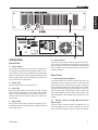
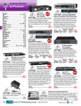
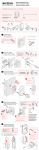
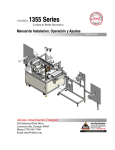
MAX 3500 User's Manual Manual del Usuario English MAX 3500 POWER AMPLIFIER AMPLIFICADOR POTENCIADO Español ENGLISH . . . . . . . . . . . . . . . . . . . . . . . . . . . . . . . . . . . . . I ESPAÑOL . . . . . . . . . . . . . . . . . . . . . . . . . . . . . . . . . . . . . II V1.1 09/25/2012 English USER'S MANUAL CONTENTS INTRODUCTION 1 FEATURES 1 GETTING STARTED 1 INSTALLATION 1 CONNECTIONS 2 OPERATION 3 PROTECTION 6 SPECIFICATIONS 7 Phonic preserves the right to improve or alter any information within this document without prior notice MAX 3500 3 IMPORTANT SAFETY INSTRUCTIONS English The apparatus shall not be exposed to dripping or splashing and that no objects with liquids, such as vases, shall be placed on the apparatus. The MAINS plug is used as the disconnect device, the disconnect device shall remain readily operable. Warning: the user shall not place this apparatus in the can be easily accessible. area during the operation so that the mains switch 1. Read these instructions before operating this apparatus. CAUTION 2. Keep these instructions for future reference. RISK OF ELECTRIC SHOCK DO NOT OPEN 3. Heed all warnings to ensure safe operation. 4. Follow all instructions provided in this document. 5. Do not use this apparatus near water or in locations where condensation may occur. 6. Clean only with dry cloth. Do not use aerosol or liquid cleaners. Unplug this apparatus before cleaning. 7. Do not block any of the ventilation openings. Install in accordance with the manufacturerís instructions. 8. Do not install near any heat sources such as radiators, heat registers, stoves, or other apparatus (including . 9. Do not defeat the safety purpose of the polarized or grounding-type plug. A polarized plug has two blades with one wider than the other. A grounding type plug has two blades and a third grounding prong. The wide blade or the third prong is provided for your safety. If the provided plug does not into your outlet, consult an electrician for replacement of the obsolete outlet. 10. Protect the power cord from being walked on or pinched particularly at plug, convenience receptacles, and the point where they exit from the apparatus. 11. Only use attachments/accessories manufacturer. CAUTION: TO REDUCE THE RISK OF ELECTRIC SHOCK, DO NOT REMOVE COVER (OR BACK) NO USER SERVICEABLE PARTS INSIDE REFER SERVICING TO QUALIFIED PERSONNEL The lightning flash with arrowhead symbol, within an equilateral triangle, is intended to alert the user to the presence of uninsulated ìdangerous voltageî within the productí magnitude to constitute a risk of electric shock to persons. The exclamation point within an equilateral triangle is intended to alert the user to the presence of important operating and maintenance (servicing) instructions in the literature accompanying the appliance. WARNING: To reduce the risk of or electric shock, do not expose this apparatus to rain or moisture. CAUTION: Use of controls or adjustments or performance may result in of procedures other than those hazardous radiation exposure. by the 12. Use only with a cart, stand, tripod, bracket, or by the manufacturer, or sold with table the apparatus. When a cart is used, use caution when moving the cart/apparatus combination to avoid injury from tipover. 13. Unplug this apparatus during lighting storms or when unused for long periods of time. service personnel. 14. Refer all servicing to Servicing is required when the apparatus has been damaged in any way, such as power-supply cord or plug is damaged, liquid has been spilled or objects have fallen into the apparatus, the apparatus has been exposed to rain or moisture, does not operate normally, or has been dropped. 4 MAX 3500 GETTING STARTED Congratulations on your purchase of the MAX 3500 power amplifier. Based on years of experience in designing and manufacturing professional audio equipment, we at Phonic designed this power amplifier for those who need an extremely powerful, reliable and sturdy amplifier. Taking advantage of its huge heat sink as well as its variable speed fan that auto-adjusts fan speed depending on the temperature of the machine during operation, MAX power amps are always able to perform. Its professional quality output and its sturdy case design make this unit great for various locations like churches, concert tours, stages, disco, pubs, or any place that requires amplifier installation. 1.Check the AC voltage before connecting the power plug to the outlet. Make sure the AC power supply shares the same voltage used in your country (For example, while some countries use 100V, others use 120V, 230V, or 240V). Please ensure your device is properly grounded. This unit is designed with great care and great attention to details, so please read this manual carefully. Look after it and keep it in a safe place for future reference. 2.Before turning on the power, make sure the gain controls are turned all the way down to prevent other equipment from harm. 3.Check your cables regularly and label each end clearly for easy identification. 4.Always turn the power off before connecting to and disconnecting from the unit. 5.NEVER use solvents to clean the unit. Clean it with a soft and damp or dry cloth. INSTALLATION MOUNTING THE UNIT FEATURES 42400 Watts per channel at 4 ohms with a 3U footprint 4High current toroidal transformer allowing high power output with low noise and low distortion 4Built in limiter with a button allowing user to disable limiter’s function 4Balanced XLR inputs Designed to fit into a standard 19-inch rack, this unit only takes up 3 units of rack space. Secure this unit with 4 rack-mount screws and cup washers. In general, power amplifiers usually are heavier than any other audio equipment, so when installing this unit onto a rack, begin placing it from the bottom of the rack. We advise leaving one rack-space between power amplifiers and other devices to guarantee better cooling (see figure 1). 4Grounding/Floating switch to avoid grounding loop 4Binding post and speakon-type outputs 4Front mounted gain controls for easy access 4Signal and Peak LED indicators to monitor performance 4Protection: short circuit, thermal, subsonic, RF protection, output DC offset, power on/off muting Figure 1 Rack Mount MAX 3500 1 English INTRODUCTION 3 1 2 English 1. Heat Ventilation This unit comes with variable speed fan that auto-adjusts fan speed depending on the temperature of the machine during operation. Be sure not to obstruct the heat vents in any way. This will ensure the amplifier is always properly ventilated. CONNECTIONS 2. XLR Input Connectors Connect your source to the XLR jacks, which are commonly used for both mobile and installation set-ups. They provide a good combination of ease of connection and resistance to corrosion. These inputs should be wired as shown in figure 2. 3. Output Connectors Binding posts and speakon connectors make up the unit’s output section. Loudspeakers can easily be connected using banana plugs, spade lugs, bare wires or speakon connector. More people prefer using speakon than other connectors because it’s the least likely to be disconnected by accident or cause electrical shock. Because speakon comes with four wires inside, you can connect to two speakers with only one channel output. Be careful when making connections since improper connecting could cause the unit to short circuit. The minimum impedance setting for STEREO and PARALLEL operation is 4 ohm, while 8 ohm is the minimum for BRIDGE MONO operation. See figure 3 for wiring information. Figure 2 Input Wiring Binding Post Output Speakon Output Figure 3 Output Wiring 2 MAX 3500 English 8 7 6 4 5 10 9 OPERATION Front Panel 4. Power Switch This switch turns the power of the unit on. Remember to turn the gain controls down before turning power on or off, even though it comes with a POWER ON / OFF MUTING feature. In general, the power amplifier should be the last piece of audio equipment to be powered on, and the first to be powered off, in a PA system. 5. Power LED This blue LED comes on when power is on. 6. Peak LED When the input signal level becomes too high, causing input signal to loss definition and to distort, this red LED comes on. When this happens, turn the gain control down until the PEAK LED no longer comes on or remains on continuously. 7. Signal LED Every channel comes with a signal LED, allowing user to monitor signal level. A minimum level of -30dBu is required for the LED to go on. MAX 3500 8. Gain Controls These two rotary knobs control the signal level of the input. These center detented controls allow precise volume setting. Slowly turn the knob clockwise to increase input level, but make sure that PEAK LED does not remain on or blink constantly. Rear Panel 9. Grounding/Floating Switch This switch allows the circuit and chassis grounds to be separated in case of a ground conflict. In normal use the switch should be in the Ground On position. Lifting the ground (Floating position) may resolve the ground conflict, but means that circuit grounding will depend on other connected components. Deficiencies in other components’ grounding will affect the sound and a serious electric fault with the amplifier could damage other components in the system. 10. Parallel / Stereo / Bridge Mono Operation Mode Switch There are three operation modes for different use. To avoid damaging your PA system, remember to turn the power off before switching from one mode to the other. 3 PARALLEL English When set to PARALLEL mode, the input signal of channel 2 parallels the input signal of Channel 1, so only one input jack is needed for the signal source. Even though the input signal of both channels parallels each other, the output level of each channel is determined by its own independent gain controls. So the two channels sharing the same signal do not share the same output level (see figure 4). Figure 4 Parallel Mode STEREO STEREO mode is the most frequently used mode among the three. Each channel is independent of the other, carrying its own input signal, with its own gain control. Stereo mode comes in left and right channels (see figure 5). A) When one channel is assigned for left channel, make sure the other channel is assigned for the right. B) User can use the unit for mono output, with one as main and the other as monitor. C) This power amplifier can also be used for bi-amplification. One channel is used for driving low frequencies while the other for driving high frequencies. Stereo (or HF) (or LF) Figure 5 Stereo Mode 4 MAX 3500 BRIDGE MONO WARNING: Bridge mono operation produces higher current output than the other two operations, thus make sure the gain is set at the proper level and speakers being used can handle the wattage amplifier produce. Proper attention to wiring is greatly needed to prevent experiencing electric shock. Bridge Mono Figure 6 Bridge Mono Mode MAX 3500 5 English This mode is for those who need high level output. It combines the power of both channels to produce the maximum amount of power the unit can handle. Make sure your speaker can handle higher wattage this mode offers. Remember, the minimum impedance requirement is 4 ohm. When bridge mono mode is selected, ensure that only the channel 1 input is in use. When using speakon, treat PIN 1+ as the “+” and PIN 2+ as the “-”; when using binding posts, treat Channel 1 + as the “+” and Channel 2 + as the “-”. Do not use Channel 2’s speakon output in this mode. When bridge mono, the gain control of Channel 1 controls the total level output (see figure 6). English 13 11 12 11. Chassis Grounding Connection Point To avoid the possibility of ground loop, this unit comes with chassis grounding point allowing it to be connected to other units for sharing a common grounding. 12. Power Cord This cord draws electricity from power outlet. Near by it, there is an indicator that tells you what voltage your unit operates in. Check the AC voltage before connecting the power plug to the outlet. Make sure the AC requirement shares the same voltage used in your country (for example, while some countries use between 110V and 120V, others use 230V to 240V). 13. Reset Switch Push this button to reset the unit in the unlikely event that it locks up. PROTECTION The unit comes with many circuitry protection features for preventing it and speakers it’s connected to from harm. SHORT CIRCUIT: When speakers short circuit, this feature protects the amplifier by cutting off the output current to the speakers. THERMAL: Heat is created during high level output – especially when during bridge operation. The unit comes with variable speed fan that auto-adjusts speed depending on the temperature of the machine during operation. However, for some reason the unit could not effectively vent out excessive heat, this feature would protect the unit from over-heating by shutting its power off. OUTPUT DC OFFSET: When direct current enters to the connection between the power amplifier and speakers, it hurts the speakers by causing drivers and cones to work under stress. This feature prevents this from happening by cutting off the output current to the speakers when such situation happens. POWER ON / OFF MUTING: There is a two to three second delay before the unit sends out any signal. During this 2-3 seconds, the system will be on mute, no signal exist this unit. SUBSONIC: Frequencies below 10Hz contain high level of energy that can be harmful and stressful for many speakers. Since normal human listening range from 20Hz to 20kHz, this unit comes with a feature that helps filter out any frequency that is below 10Hz to prevent speakers from harm. RF PROTECTION: Radio Frequency is everywhere. This feature prevents radio frequency interference by filtering out frequency signal that’s above 200kHz. This helps prevent radio program signals from entering this unit. 6 MAX 3500 SPECIFICATIONS 8Ω EIA 1kHz 0.1%THD 1600W 4Ω EIA 1kHz 0.1%THD 2400W Bridge Mono Mode 8Ω EIA 1kHz 0.1%THD 4800W Output Circuitry System 1.42 Vrms Distortion (SMPTE-IM) <0.02% Noise (unweighted 20 Hz - 20 kHz below rated output) 107 dB Frequency Response Input Impedance Cooling Indicators Controls Input Output Crossover Load Protection Power; Signal; Peak Parallel; Stereo; Bridge Mono 40 x (32 dB) XLR & 1/4” TRS Binding post & Speakon 60 Hz; 90 Hz; 120 Hz Full short circuit / Open circuit / Thermal / Ultrasonic / RF protection / stable into mismatched loads On/off muting / AC coupling / Triac crowbar (each channel) Power Consumption 1000W Power Requirement (depends on region) 100~120VAC - 220~240VAC - 50/60Hz Dimensions (mm) MAX 3500 Continous variable-speed fan - rear-to-front air flow HPF; Clip; Limiter; Operating Mode; Circuit Breaker; Grounding/Floating Protection Circuitry Physical 20 kΩ balanced; 10 kΩ unbalanced Rear panel Amplifier Protection Power Supply 20 Hz-20kHz +0/-1dB; -3dB points: 5Hz-50kHz AC power switch & Gain knobs Voltage Gain Subwoofer Output >500 @ 8Ω Front panel Operating Modes Connectors (each channel) Class H Input sensitivity @ 8Ω Damping Factor Dimensions (inches) English Stereo Mode (driving both channels) 482.6 x 133.5 x 376 mm 19” x 5.25” x 14.8” Weight (kg) 20.3 kg Weight (pounds) 44.8 lbs 7 SERVICE AND REPAIR English For replacement parts, service and repairs please contact the Phonic distributor in your country. Phonic does not release service manuals to consumers, and advice users to not attempt any self repairs, as doing so voids all warranties. You can locate a dealer near you at http://www.phonic.com/where/. WARRANTY INFORMATION Phonic stands behind every product we make with a no-hassles warranty. Warranty coverage may be extended, depending on your region. Phonic Corporation warrants this product for a minimum of one year from the original date of purchase against defects in material and workmanship under use as instructed by the user’s manual. Phonic, at its option, shall repair or replace the defective unit covered by this warranty. Please retain the dated sales receipt as evidence of the date of purchase. You will need it for any warranty service. No returns or repairs will be accepted without a proper RMA number (return merchandise authorization). In order to keep this warranty in effect, the product must have been handled and used as prescribed in the instructions accompanying this warranty. Any tampering of the product or attempts of self repair voids all warranty. This warranty does not cover any damage due to accident, misuse, abuse, or negligence. This warranty is valid only if the product was purchased new from an authorized Phonic dealer/distributor. For complete warranty policy information, please visit http://www.phonic.com/warranty/. CUSTOMER SERVICE AND TECHNICAL SUPPORT We encourage you to visit our online help at http://www.phonic.com/support/. There you can find answers to frequently asked questions, tech tips, driver downloads, returns instruction and other helpful information. We make every effort to answer your questions within one business day. [email protected] http://www.phonic.com 8 MAX 3500 Español Manual del Usuario CONTENIDO INTRODUCCIÓN 1 CARACTERÍSTICAS 1 INICIANDO 1 INSTALACIÓN 1 CONEXIONES 2 OPERACIÓN 3 PROTECCIÓN 6 ESPECIFICACIONES 7 Phonic se reserva el derecho de mejorar o alterar cualquier información provista dentro de este documento sin previo aviso. MAX 3500 9 Español 10 MAX 3500 INTRODUCCIÓN Esta unidad esta diseñada con detalles de gran atención y cuidado. Por favor de leer este manual cuidadosamente. Leerlo y guardarlo bien para referencias futuras. CARACTERÍSTICAS 2400 Vatios por canales en 4 ohms con 3U pisada. Transformador toroidal de alta corriente permitiendo salida de alta potencia con bajo ruido y baja distorsión. Limitador integrado con botón permitiendo al usuario desconectar la función del mismo. Entradas balanceadas de XLR. Interruptores de Grounding/Floating para evitar bucle de a tierra. Borne y salidas tipo conector de caja acústica (speakon). Control de montaje de ganancia frontal para acceso fácil. Indicadores de Señal y Pico LED para monitoreo de rendimiento. Protección: corto circuito, termal, subsónico, protección RF, salida Offset DC, enmudecimiento de interruptor On/Off. 1. Revise el voltaje de AC antes de conectarlo en el enchufe. Asegúrese de que la corriente de potencia comparta el mismo voltaje usado en su país (por ejemplo, si en algunos países usa 100V, otros usan 120V, 230V o 240V). Favor de asegurarse que su equipo este instalados en tierra. 2. Antes de encenderlo, asegure que el control de ganancias este completamente apagado para evitar daños a la unidad. 3. Revise sus cables regularmente y maque los terminales del mismo para facilidad de identificación. 4. Siempre apague la corriente antes de conectarse o desconectarse de la unidad. 5. Nunca use solventes para limpiar la unidad. Límpielo con trapo suave o seco. INSTALACIÓN MONTAJE DE LA UNIDAD Diseñado para caber en un estante estándar de 19 pulgada, esta unidad solo ocupa un espacio de 3 unidades. Asegure esta unidad con 4 tornillos de estante de montaje y arandelas. En general, los amplificadores de potencia normalmente son mas pesados que otros equipos de audio, así que al ser instalados esta unidad entro del estante, comience colocándolo desde abajo del mismo. Aconsejamos dejar un estante de espacio entre los amplificadores de potencia y otros equipos para garantizar mejor ventilación. (Ver ilustración 1) Figura 1 Montaje en Rack MAX 3500 1 Español Felicitaciones en la compra del Amplificador de Potencia MAX 3500, basando en los años de experiencia en diseño y manufactura profesional de equipo audio. Phonic ha diseñado este amplificador de potencia para quienes necesitan de extremada potencia de amplificadores, confiable y firme. Aprovechamos de esta gran disparador de calor tanto así como su variabilidad de velocidad de ventilación que es auto ajustable dependiendo de la temperatura de la maquina durante operación, el amplificador de potencia MAX siempre esta disponible para funcionar. La calidad profesional de salidas y el diseño de su contorno firme hacen que esta excelente unidad sea apta para diversos locales como iglesias, gira de conciertos, escenarios, discotecas, pubs o cualquier otro lugar que requiera la instalación de dicho amplificador. INICIANDO 3 1 2 Español 1.Refrigeración En esta unidad viene con diferentes velocidades de ventilación que son auto-ajustables dependiendo de la temperatura de la maquina durante la operación. Asegurese de no bloquear las ventanas de ventilación de cualquier forma. Esto es para asegurar que el amplificador este siempre ventilado apropiadamente. CONEXIONES 2. Conectores de Entrada XLR Conecte su fuente al conector hembra de XLR, que se usa comúnmente en ambas instalaciones móviles y set-ups. Esto ofrece una combinación fácil de conexión y resistencia ante la corrosión. 3. Conectores de Salida Borne y conectores de caja acústica (speakon) forman la unidad en la sección de salidas. Los altavoces pueden ser fácilmente conectadas usando el conector circular macho, spade lugs, electrodo desnudo o conectores de cajas acústica (speakon). La mayoría de la gente prefiere usar conectores de cajas acústicas más que otros conectores, porque es lo menos probable en desconectarse por accidente o causas de shock eléctrico. Debido que los conectores de caja acústica viene con cuatro cables dentro, usted puede conectarlo a dos altavoces con uno solo canal de salida. Cuidado cuando este haciendo conexiones, ya que conexiones inapropiadas puede causar cortó circuitos de la unidad. La configuración minima de impedancia para operaciones de Estereo y Paralela es de 4 ohm, mientras que el de 8 ohm es el mínimo para operaciones de Puente Mono. Ver ilustración 3 para información de en cablado. Figura 2 Cableado de Entrada Salida de Borne Salida de Conector de caja acústica (Speakon) ! Figura 3 Cableado de Salida 2 MAX 3500 Español 8 7 6 4 5 10 9 OPERACIÓN Panel Frontal 4. Interruptor de encendido Este interruptor enciende la unidad. Recuerde de apagar el control de ganancias antes de apagarlo, aun así viene con la característica de enmudecimiento de POWER ON/ OFF. En general, el amplificador de potencia debe ser la última pieza del equipo de audio en encenderse y el primero en apagarlo en un sistema de refuerzo de sonido. (Sistema PA) 5. Power LED Este encedido LED es azul cuando esta encendido. 6. Pico LED Cuando este nivel de señal de entrada está demasiada alta, causando distorsiones o perdida de definición en la señal de entrada, el LED rojo se enciende. Cuando esto ocurre, el control de ganancia se apaga hasta que el PICO LED no esté más prendido o este constantemente así. 7. Señal LED Cada canal viene junto con su señal LED, permitiendo que el usuario monitoree el nivel de señal. Un mínimo nivel de 30dBu es requerida para el LED se encienda. MAX 3500 8. Controles de Ganancia Estos dos perillas giratorios controla el nivel de señal de entrada. Este centro de control de distensión permite precisar la configuración del volumen. Lentamente encienda el pomo girando a la derecha para incrementar el nivel de entrada, pero asegúrese de que el PICO LED no este encendido o parpadeando constantemente. Panel Posterior 9. Interruptor de Grounding/Floating Este interruptor permite que el circuito y el armazón de a tierra este separado en caso de que haya cuestiones con el suelo. En el uso normal, el interruptor debería estar en posición en Tierra On(Ground on). Levantando del suelo (Floating position) puede resolver la cuestión de tierra, pero esto significa que el circuito de en tierra dependerá de otros componentes conectados. Carencia en otros componentes de a tierra afectara el sonido y serias fallas electrónicas con el amplificador puede causar dañas a otros componentes en el sistema. 10. Modo Operativo de cambio Paralela/ Estereo/Puente Mono Hay tres modos operativos para diferentes usos. Para evitar daños a su sistema de refuerzo de sonido (sistema PA), recuerde apagar la corriente antes de pasar de uno modo a otro. 3 PARALELA Español Cuando esta en el modo PARALLEL, la señal de entrada del canal 2 paralela a la señal de entrada del canal 1, y solo un conector hembra de entrada se necesita para la fuente de señal. Aun asi la señal de entrada de ambos canales paralelas cada una de la otra, el nivel de salida para cada canal es determinada por su propio control de ganancia independientemente. Así que los dos canales comparten la misma señal pero no comparten el mismo nivel de salida. (Ver ilustración 4). Entrada Mono Config. Modo Amp. a Parallel Mono Publidifusión Figura 4 MODO PARALELO ESTEREO ESTEREO es le modo más frecuentemente usado de estos tres modos. Cada canal es independiente del otro, llevando su propia señal de entrada con su propio control de ganancia. El modo Estereo viene en los canales de derecha e izquierda. (Ver ilustración 5). A) Cuando un canal es asignado para el canal izquierda, asegúrese que los otros canales estén asignados a derecha. B) El usuario puede usar la unidad para salidas mono, uno como la principal y el otro como monitor. C) El amplificador de potencia puede ser usado para bi.-amplificación. Un canal es usado para llevar la baja frecuencia mientras que el otro es para la alta frecuencia. Izq. Derch. Izq. (or HF) Config. Amp. Modo a Estereo Derch. Figura 5 MODO ESTÉREO 4 (or LF) MAX 3500 PUENTE MONO ADVERTENCIA: La operación de puente mono produce más alta corriente de salida que las otras dos operaciones, agujeréese que la ganancia esta configurada con el nivel apropiado y los altavoces que son usados puedan aguantar el voltaje producido por el amplificador. Atención apropiada para el encalvado es sumamente necesaria para prevenir shocks eléctricos. Entrada Mono Mono publidifusión (o Sub-bajo) Config. Amp. modo a Puente Mono Mono publidifusión (o Sub-bajo) Figure 6 MODO BRIDGE MONO MAX 3500 5 Español Este modo es para quienes requieren de un nivel de salida alta. Combina la potencia de ambos canales para producir la máxima potencia que la unidad puede aguantar. Asegúrese que su altavoz puede aguantar alto voltaje que este modo ofrece. Recuerde que la minima impedancia requerida es de 4 ohm. Cuando el modo de puente mono es selecto, asegure que solamente un canal 1 de entrada se use. Y cuando se el conector de caja acústica (speakon), trate con PIN1+ como ¨+¨ y PIN2+ es¨-¨. También al usar el borne trata al canal 1+ como ¨+¨ y el canal2+ como ¨-¨. No usar el modo de salida del canal 2 de speakon cuando esta en este modo. Cuando el control de ganancias del canal 1 en puente mono, controla por completo el nivel de salida. (Ver ilustración 6) Español 13 11 12 11. Armazón a Tierra de Punto de Conexión Para evitar la posibilidad el bucle de tierra, esta unidad viene junto con su punto de armazón de tierra permitiendo la conexión con otras unidades compartiendo el mismo. 12. Cable de Corriente Este cable lleva la corriente electrica del enchufe. Cerca el mismo, hay un indicador que indica que unidad de voltaje opera el equipo. Revise el voltaje AC antes de conectar el enchufe. Asegúrese que el requisito del AC comparta el mismo voltaje usado en su país (por ejemplo, si algunos países usan entre 110V y 120V otros usan 230V a 240V). 13. Botón de Reconfiguración Presione este botón para reconfigurar la unidad en el caso de que se apague. PROTECCIÓN Esta unidad viene con varias características de circuitos de protección previniéndolo de que el altavoz conectado se dañe. CORTO CIRCUITO: Cuando el altavoz este en corto circuito, esta característica protege el amplificador en cortando la corriente de salida del altavoz. TERMAL: El calor es creado durante niveles altos de salida, en especial durante puente de operación. Esta unidad viene con ventilación de variable velocidad que se auto-ajusta dependiendo de la temperatura de la maquina durante la operación. Sin embargo, si por alguna razón la unidad no pueda majenar efectivamente el exceso de aire calido, esta característica puede proteger la unidad de sobre calentarse apagándolo. BIFURCACIÓN DE SALIDA DC: Cuando Corrientes directas entran a la conexión entre el amplificador de poder y altavoz, daña el altavoz causando que los drievers y conos trabajen en tensión. Esta característica previene que eso pase y corta la corriente de entrada al altavoz cuando dicha situación ocurre. ENMUDAMIENTO POWER ON / OFF: Hay dos a tres segundos de retardo antes que la unidad envíe cualquier señal fuera. Durante estos 2 a 3 segundos, el sistema estará enmudecido y no existirá señal en la unidad. SUBSÓNICO: Frecuencias menos de 10Hz que contengan un alto nivel de energía que pueda causar daños y tensiones para muchos altavoces. Ya que el audio humano solo tiene margen desde 20Hz a 20kHz, esta unidad viene con la característica de que ayuda a filtrar fuera cualquier frecuencia que este menos de 10Hz para prevenir que el altavoz se dañe. 6 PROTECCIÓN RF: La frecuencia de radio esta por todas partes y esta característica previene interferencia de frecuencias de radio filtrándolo fuera la señal de frecuencia hasta 200kHz. Esto ayuda a prevenir señales de programación radial en interferir en la unidad. MAX 3500 ESPECIFICACIONES 8Ω EIA 1kHz 0.1%THD 4Ω EIA 1kHz 0.1%THD 1600 Vatios 2400 Vatios Modelo Puente Mono 8Ω EIA 1kHz 0.1%THD 4800 Vatios Sistema Salida de circuito Entrada sensitividad @ 8Ω Distorsión (SMPTE-IM) Clase H 1.42 Vrms <0.02% Ruido (despoderado 20 Hz -20 Khz. salida bajo tasada) 107 dB Factor de amortiguamiento Respuesta en Frecuencia Entrada de Impedancia >500 @ 8Ω 220 Hz-20kHz +0/-1dB; -3dB puntos: 5Hz-50kHz 20 kΩ balanceada; 10 kΩ desbalanceada Refrigeración Indicador Panel Frontal Controles Conectores (Para cada canal) Salidas de Sub-bajo Panel Posterior Modos Operativos Ganancias de Voltaje Entradas Salidas Divisor de frecuencia Amplificador de protección Protección de Circuito Caga de Protección Suministro de Corriente Aspecto MAX 3500 Español Modo Estereo (por medio de ambos canales) Corrientes de Consumo Requisitos de Corriente (Depende de región) Dimensiones (mm) Dimensiones (pulgadas) Peso (kg) Peso (libras) Continúa variable de velocidad delantera y postera. Potencia; Señal; Pico Interruptores de potencia AC & pulsador de ganancias HPF; Clip; Limitador; Modo Operativo; Disyuntor de circuito;Grounding/Floating Paralelo; Estereo; Puente Mono 40 x (32 dB) XLR & 1/4” TRS Borne & Conector de caja acústica (speakon) 60 Hz; 90 Hz; 120 Hz Amplificador de protección completa de corto circuito/Circuito abierto/Termal/Ultrasónico/ Protección RF/ duradera en cargas desparejas Enmudecimiento On/Off / AC coupling / Tric crowbar (en cada canal ) 1000Vatios 100~120VAC - 220~240VAC - 50/60Hz 482.6 x 133.5 x 376 mm 19” x 5.25” x 14.8” 20.3 kg 44.8 lbs 7 Español SERVICIO Y REPARACIÓN Para refacciones de reemplazo y reparaciones, por favor póngase en contacto con nuestro distribuidor de Phonic en su país. Phonic no distribuye manuales de servicio directamente a los consumidores y, avisa a los usuarios que no intenten hacer cualquier reparación por si mismo, haciendo ésto invalidará todas las garantías del equipo. Puede encontrar un distribuidor cerca de usted en http://www.phonic.com/where/. INFORMACIÓN DE LA GARANTIA Phonic respalda cada producto que hacemos con una garantía sin enredo. La cobertura de garantía podría ser ampliada dependiendo de su región. Phonic Corporation garantiza este producto por un mínimo de un año desde la fecha original de su compra, contra defectos en materiales y mano de obra bajo el uso que se instruya en el manual del usuario. Phonic, a su propia opinión, reparará o cambiará la unidad defectuosa que se encuentra dentro de esta garantía. Por favor, guarde los recibos de venta con la fecha de compra como evidencia de la fecha de compra. Va a necesitar este comprobante para cualquier servicio de garantía. No se aceptarán reparaciones o devoluciones sin un número RMA apropiado (return merchandise autorization). En orden de tener esta garantía válida, el producto deberá de haber sido manejado y utilizado como se describe en las instrucciones que acompañan esta garantía. Cualquier atentado hacia el producto o cualquier intento de repararlo por usted mismo, cancelará completamente esta garantía. Esta garantía no cubre daños ocasionados por accidentes, mal uso, abuso o negligencia. Esta garantía es válida solamente si el producto fue comprado nuevo de un representante/distribuidor autorizado de Phonic. Para la información completa acerca de la política de garantía, por favor visite http://www.phonic.com/warranty/. SERVICIO AL CLIENTE Y SOPORTE TÉCNICO Le invitamos a que visite nuestro sistema de ayuda en línea en www.phonic.com/support/. Ahí podrá encontrar respuestas a las preguntas más frecuentes, consejos técnicos, descarga de drivers, instrucciones de devolución de equipos y más información de mucho interés. Nosotros haremos todo el esfuerzo para contestar sus preguntas lo antes posible. [email protected] http://www.phonic.com 8 MAX 3500