1
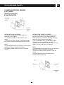
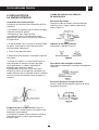
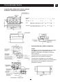
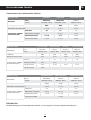
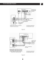
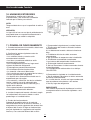
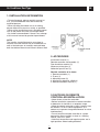
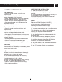
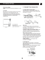
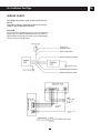
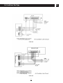
ES
Manual de instalación
Aire Acondicionado
Conducto
Modelos:
MUC 12 HF
MUC 18 HF
MUC 24 HF
MUC 30 HF
MUC 36 HF
MUC 48 HF
MUC 60 HF
Para realizar correctamente la instalación, lea este manual antes de empezar.
El contenido de este manual puede estar sujeto a cambios sin notificación para la introducción de mejoras.
Aire Acondicionado Conducto
ES
ÍNDICE
1. PRECAUCIONES....................................................................................................................................2
2. ACCESORIOS ........................................................................................................................................2
3. LUGAR DE INSTALACIÓN......................................................................................................................3
4. INSTALACIÓN DEL MANDO POR CABLE.............................................................................................4
5. INSTALACIÓN DE LA UNIDAD INTERIOR.............................................................................................4
6. INSTALACIÓN DE LA UNIDAD EXTERIOR .........................................................................................10
7. INSTALACIÓN DE LA TUBERÍA DE CONEXIÓN ................................................................................11
8. CONEXIÓN DEL TUBO DE DESAGÜE................................................................................................13
9. CONEXIONES ELÉCTRICAS ..............................................................................................................13
10. UNIDADES EXTERIORES..................................................................................................................18
11. PRUEBA DE FUNCIONAMIENTO......................................................................................................18
Aire Acondicionado Conducto
ES
1. PRECAUCIONES DURANTE
LA INSTALACIÓN
PRECAUCIONES PARA LA
INSTALACIÓN DEL MANDO A
DISTANCIA
• Para hacer una instalación correcta, lea antes
este manual.
• La instalación de la unidad debe confiarse a
personas cualificadas.
• Al instalar la unidad interior o sus conducciones,
siga las instrucciones de este manual tan
estrictamente como sea posible.
• Cuando termine todos los trabajos de
instalación, no conecte la alimentación eléctrica
hasta no haber realizado una comprobación
exhaustiva.
• No se hará ningún nuevo aviso si se realiza
alguna modificación de este manual a
consecuencia de una mejora del producto.
• Si el cable esta dañado debe ser reemplazado
por el fabricante, un servicio técnico autorizado o
por personal cualificado.
• El aparato debe instalarse de acuerdo con la
reglamentación nacional para instalaciones
eléctricas.
• No golpee ni deje caer el mando
• Antes de instalarlo, asegúrese que el lugar
elegido está dentro del espacio de recepción
• El mando debe estar al menos a 1 m de
distáncia de cualquier aparato de TV o sonido
(para evitar interferencias)
• No coloque el mando en un lugar expuesto a la
luz solar directa o a una estufa u otra fuente de
calor.
• Cuando coloque las pilas, fíjese en que los polos
positivo y negativo estén bien orientados.
NOTA
El instalador debe explicar a los usuarios el
manejo adecuado del equipo y su mantenimiento,
así como recordarles que lean y conserven los
manuales de instalación y de usuario
2. ACCESORIOS
Manual de instalación (1)
Mando a distáncia (1)
Aislante de los tubos (2)
Tubo de descarga (1)
Cinta adhesiva para sellado (1)
ELIMINACIÓN DEL
ELECTRODOMÉSTICO VIEJO.
En base a la Norma europea 2002/96/CE de
Residuos de aparatos Eléctricos y Electrónicos
(RAEE), los electrodomésticos viejos no pueden
ser arrojados en los contenedores municipales
habituales; tienen que ser recogidos
selectivamente para optimizar la recuperación y
reciclado de los componentes y materiales que los
constituyen, y reducir el impacto en la salud
humana y el medioambiente. El símbolo del cubo
de basura tachado se marca sobre todos los
productos para recordar al consumidor la
obligación de separarlos para la recogida
selectiva.
El consumidor debe contactar con la autoridad
local o con el vendedor para informarse en
relación a la correcta eliminación de su
electrodoméstico viejo.
Mando a distáncia y elementos
Mando a distáncia (1)
Base del mando (1)
Tornillo del montaje (1)
Pilas alcalinas (2)
Manual del mando a distancia (1)
2
Aire Acondicionado Conducto
ES
3. LUGAR DE INSTALACIÓN
ANTES DE LA INSTALACIÓN
1. Elija el recorrido mejor para el traslado
2. Transporte la unidad conservando la mayor
cantidad posible del embalaje original
3. Si instala la unidad sobre una parte metálica del
edificio, debe aislarla eléctricamente de acuerdo
con los reglamentos de aparatos eléctricos
pertinentes
Unidad interior
• Hay que dejar espacio suficiente para la
instalación y el mantenimiento.
• El techo debe ser horizontal, y su estructura
capaz de soportar el peso de la unidad.
• No debe haber obstáculos para la salida y
entrada de aire, y la influencia del aire exterior
debe reducirse al mínimo.
• El aire de salida ha de poder alcanzar todos los
puntos de la habitación.
• Los tubos de conexión y desagüe deben ser
fáciles de extraer.
• No debe haber radiación directa desde aparatos
de calefacción.
NOTA
Condiciones contenidas en la Directiva
89/336/CEE sobre compatibilidad electromagnética
Para evitar fluctuaciones durante el arranque del
compresor (proceso técnico), la instalación debe
cumplir las siguientes condiciones:
1. La conexión eléctrica de la unidad debe
hacerse en el cuadro de distribución principal. La
distribución debe ser de baja impedancia;
normalmente, la impedancia precisa se alcanza
con un fusible de 32 A.
2. No hay que conectar ningún otro equipo en la
misma línea eléctrica.
3. Para que la instalación sea homologable en
todos sus detalles, consulte el contrato con la
compañía eléctrica por si contiene limitaciones
relativas a productos tales como lavadoras,
acondicionadores de aire u hornos eléctricos.
4. Vea los detalles relativos a la alimentación del
acondicionador en la placa de características del
producto.
5. Consulte cualquier duda al concesionario local.
Unidad exterior
• Hay que dejar espacio suficiente para la
instalación y el mantenimiento.
• No debe haber obstáculos para la salida y
entrada de aire; la unidad no debe verse afectada
por vientos fuertes. El emplazamiento debe ser
seco y estar bien ventilado.
• La superfície de apoyo debe ser plana y
horizontal y capaz de soportar el peso de la
unidad exterior. No debe haber otras fuentes de
ruido o vibraciones.
• Hay que asegurarse de que el ruido y el aire
expulsado no molestan a los vecinos.
• No debe haber fugas de gas combustible.
• La instalación de los tubos y cables de conexión
ha de ser fácil.
IMPORTANTE
Las condiciones descritas a continuación pueden
afectar negativamente al funcionamiento de la
máquina. (Si no hay otro remedio, consulte con el
concesionario local)
a. Presencia de derivados del petróleo
b. Ambiente salino (cerca de la costa)
c. Atmósfera con gases cáusticos (sulfuros, por
ejemplo)(cerca de manantiales de aguas
termales)
d. Grandes oscilaciones de la tensión en la red
(en fábricas)
e. Espacios reducidos y cerrados
f. Cocinas con gran cantidad de vapores de aceite
g. Cerca radiaciones electromagnéticas potentes
h. En presencia de materiales o gases inflamables
i. En presencia de vapores o líquidos ácidos o
alcalinos
j. En otras condiciones especiales
3
Aire Acondicionado Conducto
ES
4. INSTALACIÓN DEL MANDO
POR CABLE
A. NORMAS DE SEGURIDAD
Por favor, lea estas normas de seguridad antes de
la instalación.
Respete todas las normas indicadas ya que son
sumamente importantes.
OTRAS PRECAUCIONES
Lugar de instalación: No lo instale en un lugar con
aceite, vapor o gas sulfuroso ya que se podría
producir deformación y fallos.
Significado de los avisos:
PELIGRO: aviso de peligro de muerte o lesiones
graves
NOTA: aviso de lesiones o daños materiales
Preparación antes de la instalación
1. Asegúrese de que se ha preparado lo siguiente.
a. Mando por cable (1)
b. Tornillo para madera (2)
c. Tornillo para montaje (2)
d. Manual de instalación (1)
e. Manual de instrucciones (1)
• Confirme que no existen fenómenos anormales
durante la prueba de funcionamiento una vez
realizada la instalación. Después, entregue el
manual al usuario.
• La instalación debe ser realizada por
profesionales. Otras personas podrían realizar una
instalación defectuosa con riesgo de descarga
eléctrica o incendio.
• Siga estas instrucciones de la forma más estricta
posible.Una instalación incorrecta puede
ocasionar descarga eléctrica o incendio.
• No desmonte su aparato de aire acondicionado
de forma desordenada. Un desmontaje aleatorio
podría ocasionar un funcionamiento anormal o
calentamiento y riesgo de incendio.
2. Preparar lo siguiente en el lugar de instalación
a. Cable apantallado 5 conductores
b. Caja de distribución
c. Manguera de cables (manguito aislante y
tornillo)
Aviso para la instalación del mando por cable
1. Estas instrucciones contienen información
sobre el procedimiento de instalación del mando.
Consulte el manual de instalación de la unidad
interior para la conexión entre el mando y dicha
unidad.
2. El circuito del mando es de baja tensión. Nunca
lo conecte a un circuito estándar de 220V/380V ni
lo ponga en la misma manguera de cables que el
circuito.
3. El cable apantallado debe estar conectado de
forma estable a tierra, o podría fallar la
transmisón.
4. No prolongue el cable apantallado cortándolo.
Si fuese necesario use un bloque de conexión.
5. Una vez finalizada la conexión, no use un
"Megger" para comprobar el aislamiento al cable
de señal.
NOTA
• No instale el aparato en un lugar donde haya
fugas de gas combustible. El gas combustible
permanecerá cerca del mando, pudiéndose
producir incendio
• El cable debe ser adecuado para la intensidad
del mando. De lo contrario podrían producirse
fugas eléctricas o calor, con el correspondiente
riesgo de incendio
• El cable debe ser adecuado para el mando. No
aplique fuerza externa en el terminal. De lo
contrario, el cable se romperá o se calentará, con
el correspondiente riesgo de incendio.
4
Aire Acondicionado Conducto
ES
4. INSTALACIÓN DEL MANDO
POR CABLE
(artículo opcional)
B. INSTALACIÓN
INSTALACIÓN EN LA PARED
• El diámetro del cable del mando debe ser
adecuado a su longitud.
• La manguera debe ser adecuada para los
cables.
• Para quitar la tapa, haga girar un destornillador
en la parte cóncava del panel inferior del mando.
INSTALACIÓN SOBRE LA PARED
• Antes de la instalación, haga un orificio que
permita el paso de un cable apantallado de 3
conductores con aislamiento de goma desde el
centro de la tapa superior del mando.
• Vea la instalación de la caja distribución para
cualquier otra información que necesite.
• Aplique sellador alrededor de los cables y en el
orificio una vez finalizada la instalación.
NOTA
• No apriete demasiado los tornillos, ya que podría
abollarse la tapa o romperse la pantalla.
• No corte lo cables cuando instale la tapa del
mando.
NOTA
• No apriete demasiado los tornillos, ya que podría
abollarse la tapa o romperse la pantalla.
• No corte lo cables cuando instale la tapa del
mando.
• Deje suficiente longitud de cable para el
mantenimiento del control
5
Aire Acondicionado Conducto
ES
6
Aire Acondicionado Conducto
ES
5. INSTALACIÓN DE
LA UNIDAD INTERIOR
FORMA DE ANCLAR LOS PERNOS
DE SUSPENSIÓN
Instalación del cuerpo principal
Instalación de los pernos de suspensión de Ø10
(4 pernos)
Estructura de madera
Coloque la tabla de madera transversalmente
sobre las vigas y luego sujete los pernos de
colgar (Figura 1)
• Consulte en la siguiente figura la forma de medir
la distancia entre los pernos
• Utilice pernos para colgar de Ø10
• La forma de hacer la instalación del techo
depende de la estructura; consulte los detalles a
un especialista
1. El techo dónde vaya a instalar la máquina debe
ser plano. Consolide las vigas del falso techo
contra posibles vibraciones.
Ladrillos de hormigón nuevos
Anclaje de los pernos (Figura 2)
2. Corte la viga del falso techo
3. Refuerce el sitio cortado y consolide la viga del
falso techo
• Coloque las tuberías y la línea eléctrica por el
techo después de montar el cuerpo principal.
Antes de empezar a trabajar, determine la
dirección que seguirán los tubos.
Especialmente en el caso de un falso techo,
coloque los tubos de refrigerante, desagüe y los
cables eléctricos de las unidades interior y exterior
hasta los puntos de conexión antes de colgar la
máquina.
Para ladrillos de hormigón originales
Utilice pernos empotrados y herrajes de enganche
(Figura 3)
Estructura del techo de vigas de acero
Instale y utilice directamente el angular de acero
de soporte (Figura 4)
Suspensión de la unidad interior (Figura 5)
(1) Suspenda la unidad interior en los pernos de
suspensión con el bloque.
(2) Coloque la unidad interior nivelada usando el
indicador de nivel, a menos que éste pueda
producir fugas.
7
Aire Acondicionado Conducto
ES
POSICIÓN DEL ESPACIO DEL TECHO, UNIDAD
INTERIOR Y PERNOS DE SUSPENSIÓN
Capacidad
(Btu/h)
A
B
C
D
E
F
9000-18000
874
910
-
-
-
19 9.53
24000
G
H
I
J
K
L
M
N
-
25
-
-
260
-
-
1000 1052 1112 1085 1470 19 9.53 252 24.5 580 290 430
1000 1052 1112 1085 1470 19 9.53 - 24.5 430
2
-
3
-
3
-
4
-
30000-48000 1350 1400 1380 1400 1430 19 9.53 252 35
1350 1400 1380 1400 1430 19 9.53 - 35
930 310 430
- 430
INSTALACIÓN DEL CUERPO PRINCIPAL
AVISO
Las figuras 7a y 7b están basadas en un modelo
de 40000 Btu/h, por lo que podrían existir
pequeñas diferencias de aspecto y funciones
con su aparato.
Cuando utilice una instalación con retorno
posterior, por favor consulte la figura 8.
Cuando curse el pedido, por favor explique
claramente si el cliente necesita una embocadura
de entrada de aire e indique si el retorno es
horizontal o vertical.
8
Aire Acondicionado Conducto
ES
INSTALACIÓN DEL PANEL
1. Desempaquetar el soporte interior.
Deslice el botón, suelte la hebilla del orificio del
soporte exterior y después desempaquete el
soporte interior.
5. Fije el cuerpo principal y el soporte exterior con
el carril metálico de agujeros (en dos posiciones).
• Cuelgue un lado del carril metálico de agujeros
en el gancho del cuerpo principal.
• Fije el otro lado del carril metálico con un tornillo
al soporte exterior.
• Corte la parte sobrante del raíl con unos alicates.
• Doble la parte superior del extremo cortado.
Figura 10
2. Suspenda el soporte exterior en el cuerpo
principal mirando hacia abajo. (4 sitios en 4
esquinas). Cuelgue la correa en el gancho del
cuerpo principal.
Carril metálico de fijación
NOTA
Cuando cuelgue el soporte exterior con el raíl, y
con la correa, presione fuerte el soporte exterior
contra el techo y fijelo.
6. Instale el soporte interior en el soporte exterior
(secuencia inversa al desembalaje del soporte
interior).
NOTA
El cable de señal del receptor del mando a
distancia debe salir a través del conducto de aire.
NOTA
Conecte el receptor del mando a distancia con los
cables de señal de la unidad interior y fíjelo.
3. Fije el soporte exterior y el conducto de aire con
tornillos. El tornillo se debe instalar de abajo
arriba.
7. Instale el mando a distancia.
4. Cuelgue el soporte exterior hasta que esté
firmemente adherido al techo.
9
Aire Acondicionado Conducto
ES
6. INSTALACIÓN DE
LA UNIDAD EXTERIOR
IMPORTANTE
• Mantenga la unidad protegida de la luz solar
directa y de otras fuentes de calor. Si no hay otro
remedio, cúbrala con una protección
• En lugares próximos a la costa o muy altos,
donde los vientos sean fuertes, instale la unidad
contra la pared para asegurar un funcionamiento
normal
• Utilice un deflector en caso necesario
• Si el viento es extraordinariamente fuerte, impida
que circule hacia la parte trasera de la unidad
(Figura 16)
• Coloque la unidad exterior tan próxima a la
interior como sea posible. Las distancias mínimas
entre la unidad exterior y los obstáculos descritos
en la figura de instalación no significan que no se
pueda montar un cortavientos. Deje libres dos de
las tres direcciones A,B,C.
Figura 18
Transporte e instalación
• Como el centro de gravedad de la unidad no
coincide con el centro geométrico, tenga cuidado
cuando levante con un elevador
• No levante nunca agarrándola por la entrada de
aire, pues se deformaría
• No toque el ventilador con las manos ni con
otros objetos
• No la incline más de 45° grados, ni la apoye
sobre un lado
• Sujete las patas de la unidad con pernos para
impedir que se caiga en caso de terremoto o de
vientos fuertes
• Disponga una base de hormigón (Figura 18)
Figura 16
Espacio necesario para la instalación
y el mantenimiento (Figura 17)
Si es possible, retire los obstáculos próximos para
evitar que el funcionamiento se degrade por falta
de circulación de aire. Deje libres dos de las tres
direcciones A,B,C.
Figura 17
10
Aire Acondicionado Conducto
ES
7. INSTALACIÓN DE LA TUBERIA
DE CONEXIÓN
Compruebe que la diferencia de alturas entre las
unidades interior y exterior, la longitud del tubo de
refrigerante y el número de codos, satisfacen los
requisitos siguientes:
Observaciones sobre la forma
de doblar los tubos
• El ángulo de doblez no debe superar los 90°
• La posición del codo debe fijarse a ser posible
en el tubo que va a doblarse. Cuanto mayor sea el
codo, mejor.
• No doble un tubo más de tres veces
Máxima diferencia de alturas:........................10 m
(Si la diferencia es superior a 10m, coloque la unidad
exterior sobre la interior)
Longitud del tubo refrigerante:........menos de 3 m
Número de codos:.........................menos de 10 m
Doble el tubo de conexión
de pared más delgado
• Corte una concavidad de la forma deseada en la
parte del codo del tubo de aislamiento
• Después la tubería (cúbrala con cinta después
de doblar)
• Para evitar que se apalste o se deforme, doble el
tubo con el mayor radio posible
• Utilice una herramienta especial si tiene que
formar radios pequeños
• Durante la instalación, evite que entre aire, polvo
u otras impurezas dentro de los tubos.
• El tubo de conexión no debe instalarse hasta no
haber fijado las unidades interior y exterior.
• Mantenga seco el tubo de conexión y evite que
entre humedad durante la instalación
Forma de conectar los tubos
Mida la longitud necesaria de tuberia de conexión
como se describe en los párrafos siguientes:
a.Conecte primero la unidad interior y después la
exterior
• Doble la tubería correctamente. No la estropee.
Uso del tubo de latón comercial
Asegúrese de que utiliza los mismos materiales
de aislamiento cuando compre el tubo de latón
(más de 9 mm de espesor)
Colocación del tubo
a. Perfore un orificio en la pared (suficiente para el
pasamuros, que suele tener 90 mm) y coloque
después el pasamuros y su tapa.
IMPORTANTE
• Unte con aceite refrigerante la tubería
abocardada y las tuercas de las juntas y dele 3 o
4 vueltas a mano antes de apretarlas con una
llave (Figura 19)
• Cuando conecte o desconecte las tuberías, use
siempre dos llaves a la vez.
b. Reúna los tubos de conexión y los cables y
forme un haz apretado con cinta adhesiva. No
deje que entre aire, pues podría producir goteo de
agua por condensación
b. La válvula de cierre de la unidad exterior debe
estar completamente cerrada (en su estado
original). Siempre que haga una conexión, afloje
primero las tuercas de la parte de la válvula de
cierre y conecte enseguida el tubo abocardado
(en 5 minutos). Si las tuercas permanecen flojas
durante mucho tiempo, puede entrar polvo o
suciedad en el circuito y provocar más tarde una
avería. Por ello, antes de la conexión, expulse el
aire del tubo refrigerante
c. Debe expulsar el aire (consulte vaciado del
aire) después de conectar la conducción de
refrigerante a las unidades interior y exterior.
Apriete, después, las tuercas en los puntos de
reparación.
c. Pase los tubos unidos por el pasamuros desde
el exterior para que el tubo de refrigerante que
conecta las unidades interior y exterior tenga un
flujo sin obstáculos.
d. Use un detector o agua jabonosa para
cercionarse que no hay fugas.
e. Cubra la junta del tubo de conexión con la
unidad interior con la funda aislante/anitruidos
(accesorios) y sujétela bien con cinta adhesiva
para evitar fugas.
Figura 19
11
Figura 20
Figura 21
Aire Acondicionado Conducto
ES
Abocardado
1. Corte la tubería con un cortatubos.
2. Inserte en la tubería una tuerca para unión
abocardada y dé a la tubería la forma
abocardada.
Diámetro
exterior (mm)
Ø6,35
Ø9,53
Ø12,7
Ø16
Ø19
5. Cuando haya terminado de bombear, cierre del
todo la llave de baja de la válvula de colector y
pare la bomba de vacío.
• Cuando haya bombeado durante más de 15
minutos, confirme que el indicador del
manovacuómetro señala 1,0 x 10⁻⁵ Pa (-76 cmHg).
6. Afloje y retire la tapa cuadrada de las válvulas
de cierre A y B para abrirlas del todo; sujételas
después.
7. Desmonte el latiguillo de la boca de reparación
de la válvula de cierre A y apriete la tuerca.
A (mm)
Máx.
8,3
12,4
15,8
19,0
23,3
Máx.
8,3
12,0
15,4
18,6
22,9
Apriete las tuercas
• Coloque la tubería de conexión en
la posición adecuada, apriete las
tuercas con la mano y después
apriételas con una llave.(Figura 24)
Figura 24
IMPORTANTE
IMPORTANTE
Un par de apriete excesivo dañará el
abocardado; si es insuficiente, permitirá fugas.
Determine el par de apriete en la tabla 2.
Tamaño de
la tubería
Ø6,35
Ø9,53
Ø12,7
Ø16
Ø19
A Válvula de baja
B Válvula de alta
C, D Juntas de la
tubería de conexión
a la unidad interior.
Par
1420~1720 N · cm (144~176kgf · cm)
3270~3990 N · cm (333~407kgf · cm)
4950~6030 N · cm (504~616kgf · cm)
6180~7540 N · cm (630~770kgf · cm)
9720~11860 N · cm (990~1210kgf · cm)
Tabla 2
Extraiga el aire con una bomba de vacío
(Figura 25) (Consulte en este manual la forma de
utilización de la válvula de colector)
1. Afloje y retire las tuercas de mantenimiento de
las válvulas de cierre A y B y conecte el latiguillo
de la válvula de colector al terminal de
mantenimiento de la válvula de cierre A
(asegúrese de que las dos válvulas de cierre A y
B están cerradas).
2. Conecte la junta del latiguillo a la bomba de
vacío.
3. Abra del todo la llave de baja de la válvula de
colector.
4. Ponga en marcha la bomba de vacío. Cuando
comience el bombeo, afloje un poco la tuerca del
terminal de mantenimiento de la válvula de cierre
B para comprobar si entra el aire (cambia el ruido
de la bomba y el indicador del manovacuómetro
marca por debajo de cero). Después, apriete la
tuerca.
12
Se deben abrir todas las válvulas de cierre antes
de la prueba de funcionamiento. Todos los
acondicionadores tienen dos válvulas de cierre de
distintos tamaños en el lado de la unidad exterior
que funcionan respectivamente como válvula de
baja y válvula de alta. (Figura 26)
CARGA AÑADIDA
• Cuando la longitud de la tubería única es menor
de 5 m, no es necesario añadir refrigerante
después de purgar.
• Cuando la longitud de la tubería única es de más
de 5 m, hay que añadir la cantidad de refrigerante
indicada a continuación (unidades en gramos):
Longitud del
Método de purga del aire
tubo de conexión
Cantidad extra de refrigerante
que se debe cargar
Menos de 8 m
Utilice el refrigerante de
la unidad exterior
Más de 8 m
Utilice la bomba de vacío
30 g (longitud, 5 m) (20000 btu/h.)
o una botella de refrigerante 65 g (longitud, 5 m) (24000 btu/h.)
Aire Acondicionado Conducto
ES
COMPROBACIÓN DE FUGAS
Compruebe todas las juntas con el detector de
fugas o con agua jabonosa.
9.CONEXIONES ELÉCTRICAS
Conexiones
1. El acondicionador debe utilizar una línea
independiente de la tensión especificada.
2. La alimentación eléctrica debe disponer de
toma de tierra, que debe conectarse a las tomas
correspondientes de las unidades interior y
exterior.
3. Las conexiones debe realizarlas personal
cualificado y siguiendo los esquemas eléctricos.
4. Hay que montar un protector de corrientes de
fuga de conformidad con el reglamento eléctrico
nacional
5. Asegúrese de colocar correctamente los cables
de alimentación y señalización para evitar las
interferencias y el contacto con el tubo de
conexión o el cuerpo de la válvula de cierre.
6. El cable de conexión que viene con el
acondicionador tiene 10 m. Si necesita uno más
largo, asegúrese de elegir uno del mismo tipo. En
general, no deben conectarse entre sí dos cables
retorciendo las puntas; hay que soldarlos y
protegerlos con cinta aislante
7. No conecte la alimentación antes de haber
comprobado las conexiones que acaba de
realizar.
AISLAMIENTO
• Asegúrese de cubrir con material aislante todas
las partes expuestas de las juntas abocardadas y
la tubería de refrigerante en los lados del líquido y
del gas. Compruebe que están bien ajustados.
• Un aislamiento incompleto puede causar
condensación de agua.
8. CONEXIÓN DEL TUBO
DE DESAGÜE
1. Instalación del tubo de desagüe
de la unidad interior
La salida tiene una rosca PTI; utilice materiales
para sellado y fundas de tubos cuando conecte
los tubos de PVC
IMPORTANTE
• El tubo de desagüe de la unidad interior debe
aislarse térmicamente para evitar la condensación
de humedad, al igual que las conexiones a dicha
unidad.
• Utilice adhesivo de PVC para conectar los tubos
y asegúrese de que no hay fugas.
• Tenga cuidado para no aplicar presión en el lado
de los tubos de la unidad interior.
• La pendiente descendente del tubo de desagüe
debe ser de al menos 1/100, y el tubo no debe
tener ondulaciones.
• La longitud transversal total del tubo de desagüe
no debe ser mayor de 20m; si este recorrido es
largo, hay que colocar soportes para evitar que se
doble.
• Consulte las siguientes figuras para ver los
detalles de instalación de los tubos.
2.Prueba del desagüe
• Compruebe que el tubo de desagüe no está
obtruido.
• En edificios nuevos, esta prueba debe hacerse
antes de montar el falso techo
13
Aire Acondicionado Conducto
ES
Características de la alimentación eléctrica
18000
18000 Btu/h
Btu/h
24000
24000 Btu/h
Btu/h
24000-30000 Btu/h
Monofásico
Monofásico
Trifásico
220-240V - 50 Hz
220-240V - 50 Hz
380V 3N - 50 Hz
40/25
40/25
20/15
3 x 2.0
3 x 2,5
5 x 1,5
2,0
2,5
1,5
-
3 x 2,5
5 x 1,5
Señal electrica fuerte
5 x 2,0
3x2
5 x 1,0
Señal electrica débil
1 x 0,5
2 x 1,0
2 x 0,5
Tipo (frío
Tipo
(fríoyycalor)
calor)
Fases
Alimentación
Tensión
Fusible (A)
2
Alimentación ud. Interior (mm )
Cable tierra
Conexión de las unidades
2
interior/exterior (mm )
Alimentación ud. exterior
30000-36000 Btu/h
36000-48000 Btu/h
9000 Btu/h
12000-18000 Btu/h
Monofásico
Trifásico
Monofasico
Monofasico
220-240V - 50 Hz
380V 3N - 50Hz
220-240V - 50 Hz
220-240V - 50 Hz
40/25
20/15
40/25
40/25
3 x 3,5
5 x 2,5
3 x 2,0
3 x 2,0
3,5
2,5
2,0
2,0
3 x 3,5
5 x 2,5
-
-
3 x 2,5
3 x 1,0
3 x 2,5
3 x 2,5
1 x 0,5
-
-
-
24000-36000 Btu/h
24000-30000 Btu/h
36000-48000 Btu/h
Monofásico
Trifásico
Trifásico
220-240V - 50 Hz
380V3N - 50 Hz
380V 3N - 50 Hz
40/20
25/16
25/16
3 x 2.5
5 x 1,5
5 x 2,5
2,5
1,5
2,5
Alimentación ud. exterior
3 x 2,5
5 x 1,5
5 x 2,5
Señal electrica fuerte
1 x 1,0
2 x 1,0
1 x 1,5
Señal electrica débil
-
2 x 0,5
-
Tipo (frío y calor)
Fases
Alimentación
Tensión
Fusible (A)
2
Alimentación ud. Interior (mm )
Cable tierra
Conexión de las unidades
Alimentación ud. exterior
2
interior/exterior (mm )
Señal electrica fuerte
Señal electrica débil
Tipo (frío y calor)
Fases
Alimentación
Tensión
Fusible (A)
2
Alimentación ud. Interior (mm )
Cable tierra
Conexión de las unidades
2
interior/exterior (mm )
PRECAUCIÓN
Se debe incorporar un interruptor de conexión a la red según las normas vigentes de cada país
14
Aire Acondicionado Conducto
ES
DIAGRAMA DE CONEXIONES
Conecte correctamente a tierra el acondicionador.
De otro modo, las fugas a tierra podrían degradar
el comportamiento antiparasitario de la unidad
PRECAUCIÓN
A continuación se muestra el diagrama de
cableado tanto del modelo sólo frío como bomba
de calor de la serie R410A. Al realizar las
conexiones, por favor seleccione el diagrama
correspondiente ya que, en caso contrario, se
podrían producir averías.
Figura 30
15
Aire Acondicionado Conducto
ES
16
Aire Acondicionado Conducto
ES
17
Aire Acondicionado Conducto
ES
10. UNIDADES EXTERIORES
Desmonte los tornillos de la tabla de
mantenimiento y tire de ella en la dirección
indicada por la flecha para retirarla .
NOTA
Tenga cuidado de no rayar la superficie al realizar
esto.
ATENCIÓN
La figura 35 se basa en un tipo de unidad exterior
que puede tener una apariencia diferente de la
unidad exterior que usted ha adquirido.
Figura 35
1) Compruebe lo siguiente en la unidad interior:
a. El interruptor del mando a distancia funciona
correctamente
b. Los botones del mando a distancia funcionan
bien
c. El deflector del aire de salida se mueve
normalmente
d. Se ajusta bien la temperatura de la habitación
e. El indicador se enciende normalmente
f. Los botones del temporizador funcionan bien
g. El desagüe funciona correctamente
h. No hay vibraciones ni ruidos anormales durante
el funcionamiento
i. El acondicionador calienta bien si es del tipo
CALOR-FRIO
11. PRUEBA DE FUNCIONAMIENTO
1. Cuando termine toda la instalación, debe hacer
una prueba de funcionamiento
2. Confirme los puntos siguientes antes de
efectuar la prueba:
• Las unidades interior y exterior están
correctamente instaladas
• Los tubos y conexiones eléctricas están
correctamente instalados
• Se ha comprobado que no hay fugas en el
sistema de tubos de refrigerante
• El desagüe no presenta obstrucciones
• El aislamiento térmico funciona bien
• La conexión a tierra está bien hecha
• Se ha tenido en cuenta la longitud de los tubos y
la mayor capacidad de refrigerante
• La tensión de la alimentación coincide con la
especificada para el equipo
• Las entradas y salidas de aire de las unidades
interior y exterior no están obstaculizadas
• Las válvulas de cierre de los lados de gas y
líquido están abiertas
• Se ha precalentado el acondicionador
conectando la alimentación eléctrica
2)Compruebe lo siguinete en la unidad exterior:
a. No se producen vibraciones o ruidos anormales
durante el funcionamiento
b. La salida de aire, el ruido o el agua condensada
que se producen no molestan a los vecinos
c. No hay fugas de refrigerante
IMPORTANTE
Una función de protección impide que la unidad
arranque durante los 3 minutos siguientes a una
parada.
3. Instale el soporte del mando a distancia según
las indicaciones del usuario, donde su señal
pueda llegar a la unidad interior.
4. Prueba de funcionamiento
Coloque el acondicionador en el modo de
REFRIGERACIÓN con el mando a distancia, y
compruebe los puntos siguientes de acuerdo con
el Manual del usuario. Si algo no funciona bien,
corríjalo siguiendo las sugerencias del capítulo
Averías y sus causas del Manual del usuario.
18
ES
Manual de instalación
®
SALVADOR ESCODA S.A.
BARCELONA - Central Ventas:
Provença, 392, plantas 1 y 2 - 08025 BARCELONA
Tel. 93 446 27 80 - Fax 93 456 90 32
[email protected]
www.salvadorescoda.com
BARCELONA - T. BCN Centro:
Rosselló, 430-432 bjs.
08025 Barcelona
Tel. 93 446 20 25
Fax 93 446 21 91
ALMERÍA - Delegación:
c/. Carrera del Doctoral, 22
ALMERÍA
Próxima apertura
Marzo 2007
MADRID 1 - Delegación:
Av. de Castilla, 26 naves 10-11
28830 S. Fernando de Henares
Tel. 91 675 12 29
Fax 91 675 12 82
SEVILLA 1 - Delegación:
Joaquín S. de la Maza, PICA
p. 170, m. 6-7-8. CP 41007
Tel. 95 499 97 49
Fax 95 499 99 14
BADALONA - T. BCN Norte:
Industria 608-612
08918 Badalona
Tel. 93 460 75 56
Fax 93 460 75 71
CÁDIZ - Delegación:
Pol. El Portal, c/. Sudáfrica s/nº
P. E. Mª Eugenia, 1. 11408 Jerez
Tel. 956 35 37 85
Fax 956 35 37 89
MADRID 2 - Delegación:
Fragua, 8 - Pol. Ind. Cantueña
28944 Fuenlabrada (Madrid)
Tel. 91 642 35 50
Fax 91 642 35 55
SEVILLA 2 - Delegación:
PIBO, Av. Valencina p. 124-125
41110 Bollullos Mitación
Tel. 95 577 69 33
Fax 95 577 69 35
HOSPITALET - Tienda BCN Sur:
Av. Mare de Déu de Bellvitge, 246-252 08907 L'Hospitalet Ll.
Tel. 93 377 16 75
Fax 93 377 72 12
CASTELLÓN - Delegación:
Av. Enrique Gimeno, 24
Pol. C. Transporte. CP 12006
Tel. 96 424 72 11
Fax 96 424 72 03
MADRID 3 - Tienda:
Av. Emperatriz Isabel, 19
28019 Madrid
Tel. 91 469 14 52
Fax 91 469 10 36
TARRAGONA - Delegación:
c/. del Ferro, 18-20
Pol. Riu Clar. 43006 Tarragona
Tel. 977 20 64 57
Fax 977 20 64 58
BARBERÀ - Tienda Vallès:
Marconi, 23
08210 Barberà del Vallès
Tel. 93 718 68 26
Fax 93 729 24 66
CÓRDOBA - Delegación:
Juan Bautista Escudero, 219 C
Pol. Las Quemadas. CP 14014
Tel. 957 32 27 30
Fax 957 32 26 26
MÁLAGA - Delegación:
c/. Brasilia, 16 - Pol. El Viso
29006 Málaga
Tel. 952 04 04 08
Fax 952 04 15 70
VALENCIA 1 - Delegación:
Río Eresma, s/n.º
46026 Valencia
Tel. 96 395 62 64
Fax 96 395 62 74
MATARÓ - Tienda Maresme:
Polígono Ind. Plà d'en Boet
Carrasco i Formiguera, 29-35
08302 Mataró
Tel. 93 798 59 83
GIRONA - Delegación:
c/. Alacant, 47 nave B
Pol. Can Xirgú - 17005 Girona
Tel. 972 40 64 65
Fax 972 40 64 70
MURCIA 1 - Delegación:
Cuatro Caminos, 56
30007 Murcia
Tel. 968 23 65 28
Fax 968 20 43 91
VALENCIA 2 - Delegación:
P. I. nº 7, c/.Brosquil, n. III-IV
46540 El Puig (Valencia)
Tel. 96 147 90 75
Fax 96 147 90 52
ALBACETE - Delegación:
Pol. Campollano, D, p. 8-10
02007 Albacete
Tel. 967 19 21 79
Fax 967 19 22 46
GRANADA - Delegación:
Pol. Juncaril, c/. Lanjarón, 10
18220 Albolote (Granada)
Tel. 958 49 10 50
Fax 958 49 10 51
MURCIA 2 - Delegación:
Pol. Oeste, Principal, p. 21/10
30169 San Ginés (Murcia)
Tel. 968 88 90 02
Fax 968 88 90 41
VALENCIA 3 - Delegación:
Parque Empresarial Tactica
c/. 2A, nº 10. 46980 Paterna
Tel. 96 134 52 47
Fax 96 134 52 48
ALICANTE 1 - Delegación:
Artes Gráficas, 10-12
03008 Alicante
Tel. 96 511 23 42
Fax 96 511 57 34
JAÉN - Delegación:
Pol. Olivares, Cazalilla, p. 527
23009 Jaén
Tel. 953 28 03 01
Fax 953 28 03 46
PALMA DE MALLORCA - Del.:
c/. Gremi de Boneters
Pol. Son Castelló - CP 07009
Tel. 971 43 27 62
Fax 971 43 65 35
ZARAGOZA - Delegación:
Polígono Argualas, nave 51
50012 Zaragoza
Tel. 976 35 67 00
Fax 976 35 88 12
ALICANTE 2 - Delegación:
c/. Metal·lurgia, Pol. Les Galgues
03750 Pedreguer (Alicante)
Tel. 96 645 67 55
Fax 96 645 70 14
LLEIDA - Delegación:
Pol. Segrià, N-230, km 7,4
25123 Torrefarrera (Lleida)
Tel. 973 75 06 90
Fax 973 75 06 95
REUS - Delegación:
Víctor Català, 46
43206 Reus (Tarragona)
Tel. 977 32 85 68
Fax 977 32 85 61
REPRESENTACIONES:
985 36 21 28
Asturias
924 33 07 18
Mérida
Pontevedra 986 86 07 76
EN
Installation Manual
Air Conditiones
Duct type
Model:
MUC 12 HF
MUC 18 HF
MUC 24 HF
MUC 30 HF
MUC 36 HF
MUC 48 HF
MUC 60 HF
For correct installation, read this manual before starting installation.
This manual may be subject to change without notice for purpose of improvement..
Air Conditioner Duct Type
EN
CONTENT
1. INSTALLATION INFORMATION..............................................................................................................2
2. ACCESSORIES.......................................................................................................................................2
3. CAUTION ON REMOTE CONTROLLER INSTALLATION.......................................................................2
4. INSTALLATION PLACE...........................................................................................................................3
5. INDOOR UNIT INSTALLATION...............................................................................................................4
6. INSTALL THE CONNECTING PIPE........................................................................................................7
7. CONNECT THE DRAIN PIPE.................................................................................................................9
8. WIRING.................................................................................................................................................10
9. OUTDOOR UNIT...................................................................................................................................14
10. TEST OPERATION..............................................................................................................................14
Air Conditioner Duct Type
EN
1. INSTALLATION INFORMATION
• To install properly, please read this manual at
first. The air conditioner must be installed by
qualified persons.
• When installing the indoor unit or its tubing,
please follow this manual as strictly as possible.
• When all the installation work is finished, please
turn on the power only after a thorough check.
• No further announcement if there is any change
of this manual caused by product improvement.
NOTE
The installor should illustrate to users how to
correctly use and maintain the air-conditioner, as
well as remind users to carefully read and keep
both Installation Manual and Owner's Manual well.
2. ACCESORIES
Installation manual (1)
Remote controller subassembly (1)
Pipe insulation material (2)
Accessory drain pipe (1)
Adhesive tape for seal (1)
Remote controller & its frame
1. Remote controller (1)
2. Frame (1)
3. Mounting screw (2)
4. Alkaline dry batteries (AM4)(2)
5. Remote controller manual (1)
3.CAUTIONS ON REMOTE
CONTROLLER INSTALLATION
• Never throw or beat the controller.
• Before installation, operate the remote controller
to determine its location in a reception range.
• Keep the remote controller at least 1mapart from
the nearest TV set or stereo equipment. (It is
necessary to prevent image disturbances or noise
interferences.)
• Do not install the remote controller in a place
exposed to direct sunlight or close to a heating
source, such as a stove.
• Note that the positive and negative poles are in
right positions when loading batteries.
2
Air Conditioner Duct Type
EN
NOTES BEFORE INSTALLATION
1. Select the correct carry-in path.
2. Move this unit as originally packaged as
possible.
3. If the air conditioner is installed on a metal part
of the building, it must be electrically
insulated according to the relevant standards to
electrical appliances
4. INSTALLATION PLACE
The Indoor Unit
• There is enough roomfor installation and
maintenance.
• The ceiling is horizontal, and its structure can
endure the weight of the indoor unit.
• The air outlet and the air inlet are not impeded,
and the influence of external air is the least.
• The air flow can reach throughout the room.
• The connecting pipe and drainpipe could be
extracted out easily.
• There is no direct radiation fromheaters
NOTE
Remark per EMC Directive 89/336/EEC
For to prevent flicker impressions during the start
of the compressor (technical process),
following installation conditions apply.
The Outdoor Unit
• There is enough room for installation and
maintenance.
• The air outlet and the air inlet are not impeded,
and can not be reached by strong wind.
• The place is dry and ventilative.
• The support is flat and horizontal and can stand
the weight of the outdoor unit. And no additional
noise or vibration.
• Your neighborhood will not feel uncomfortable
with the noise or expelled air.
• There is no leakage of combustible gas.
• It is easy to install the connecting pipe or cables.
1. The power connection for the air conditioner has
to be done at the main power distribution.
The distribution has to be of a low impedance,
normally the required impedance reaches
a 32Afusing poinat t.
2. No other equipment has to be connected with
this power line.
3. For detailed installation acceptance, please
refer to your contract with the power supplier
if restrictions do apply for products like washing
machines, air conditioners or electrical
ovens.
4. For power details of the air conditioner, refer to
the rating plate of the product.
5. For any question contact your local dealer.
CAUTIONS
Location in the following places may cause
malfunction of the machine. (If unavoidable, please
consult your local dealer.)
a. There exists petrolatum.
b. There is salty air surrounding(near the coast).
c. There is caustic gas(the sulfide, for example)
existing in the air (near a hot spring).
d. The Volt vibrates violently(in the factories).
e. In buses or cabinets.
f. In kitchen where it is full of oil gas.
g. There is strong electromagnetic wave existing.
h. There are inflammable materials or gas.
i. There is acid or alkaline liquid evaporating.
j. Other special conditions.
3
Air Conditioner Duct Type
EN
THE INSTALLATION OF HANGING
SCREW BOLTS:
5. INDOOR UNIT INSTALLATION
Install the main body
Installingf10 hanging screw bolts. (4 bolts)
Please refer to the following figure for the distance
measurement between the screw bolts.
Please install with 10 hanging screw bolts.
The handling to the ceiling varies fromthe
constructions, consult the construction personnels
for the specific procedures.
Wooden construction
Put the square timber traversely over the
roof beam, then install the hanging screw
bolts. (Refer to Chart 1)
1. The ceiling where the works will be done must
be flat. Consolidate the roof beamfor possible
vibration.
2. Cut off the roof beam.
3. Strengthen the place cut off, and consolidate
the roof beam.
New concrete bricks
Inlaying or embedding the screw bolts.
(Refer to Chart 2)
Carry out the pipe and line operation in the ceiling
after finishing the installation of the main body.
While choosing where to start the operation,
determine the direction of the pipes to be drawn
out. Especially in case there is a ceiling, position
the refrigerant pipes, drain pipes, indoor & outdoor
lines to the connection places before hanging up
the machine.
The installation of hanging screw bolts.
For Original concrete bricks
Use embedding screw bold, crock and stick
harness. (Refer to Chart 3)
Steel roof beamstructre
Install and use directly thesupporting angl
steel. (Refer to chart 4)
OVERHANGING THE INDOOR UNIT
(1)Overhang the indoor unit onto the hanging
screw bolts with block
(2) Position the indoor unit in a flat level by using
the level indicator, unless it may cause leakage.
4
Air Conditioner Duct Type
EN
INSTALLING THE DUST PROOF NET AND
CANVAS AIR PASSAGE
1. Install the dust proof net according to the
installation manual.
2. Install the canvas air passage underneath the
dust proof net.
Pipe Connection
The static pressure in the outside of the unit is
39.2Pa (maximum98Pa), the length of the
air pipe attached is determined by this parameter.
THE POSITIONING OF CEILING HOLE AND
INDOOR UNIT AND HANGING SCREW BOLTS
Capacity
(Btu/h)
A
M
N
18000
1000 1050 1030 1050 1080 12,7 6,35 252 24,4 290 290 1
2
B
C
D
E
F
G
H
I
J
K
24000-30000 1000 1050 1030 1050 1080 16
9.53 252 24.4 580 290 2
3
30000-48000 1350 1400 1380 1400 1430 19
12,7 252 35
4
INSTALL THE MAIN BODY
930 310 3
NOTICE
This chart is based on 40000Btu/h type, So, a little
differences may exist on the outlook and functions
fromyours.
When using a back-air installation, please refer to
the following:
Please explain clearly when ordering if customers
need air inlet box. And note it is below
air inlet or back air-inlet.
5
Air Conditioner Duct Type
EN
PANEL INSTALLATION
5. Fix the main body and the outside frame with
the fix board of waist-shape hole (in two places)
• Hang one side of the fix board of the waistshaped hole on the hook of the main body.
• Tighten the other side of the board with screw to
the outside frame.
• Cut off the surplus part of the board with pliers.
• Bend the top of the broken end.
1. Unload inner frame.
Slide the knob, release the buckle fromthe outside
frame hole, then unload the inner frame.
2. Hang the outside frame on the main body with
face down. (4 places at 4 corners).
Hang the belt on the hook of the main body.
NOTE
When hanging up the outside frame with the fix
board of waist-shaped hole and the belt, stick the
outside frame tightly to the ceiling and fix it.
NOTE
The signal wire of the remote control receiver must
be drawn out through the canvas air passage.
3. Fix the outside frame and the canvas air
passage with screws. Screw must be fixed on from
the bottom to the top.
6. Install the inner frame on the outside frame (the
inverse sequence of unloading the inner frame).
NOTE
Connect the remote control receiver with the
indoor unit signal wires and fix it.
7. Install remote controller.
4. Hang up the outside frame until it sticks to the
ceiling tightly.
6
Air Conditioner Duct Type
EN
6. INSTALL THE CONNECTING PIPE
CAUTION
Check whether the height drop between the indoor
unit and outdoor unit, the length of refrigerant pipe,
and the number of the bends meet the following
requirements:
NOTICE FOR BENDABLE PIPE
• The bending angle should not exceed 90 .
• Bending position is preferably in the middle of the
bendable pipe. The larger the bending radius the
better it is.
• Do not bend the pipe more than three times.
The max height drop........................................20m
(If the height drop is more than 10m, you had better put the
outdoor unit over above the indoor unit)
The length of refrigerant pipe............less than 30m
The number of bends...........................less than 15
BEND THE CONNETCTING PIPE OF SMALL
WALL THICKNESS
• Cut out a desired concave at the bending part of
the insulating pipe.
• Then expose the pipe (cover it with tapes after
bending).
• To prevent collapsing or deforming, please bend
the pipe at its biggest radius.
• Use bender to get a small radius pipes.
CAUTION
• Do not let air, dust, or other impurities fall in the
pipe systemduring the time of installation.
• The connecting pipe should not be installed until
the indoor and outdoor units have been fixed
already.
• Keep the connecting pipe dry, and do not let
moisture in during installation.
Use the market brass pipe
Be sure to use the same insulating materials when
you buy the brass pipe (more than 9mmthick).
CONNECT THE DRAIN PIPE
Measure the necessary length of the connecting
pipe, and make it by the following way.
1) Connect the indoor unit at first, then the outdoor
unit.Bend the tubing in proper way. Do not harm to
them.
1. Locate The Pipes
1) Drill a hole in the wall (suitable just for the size
of the wall conduit, 90mmin general), then set on
the fittings such as the wall conduit and its cover.
2) Bind the connecting pipe and the cables
together tightly with binding tapes. Do not let air in,
which will cause water leakage by condensation.
3) Pass the bound connecting pipe through the
wall conduit fromoutside. Be careful of the pipe
allocation to do no damage to the tubing.
4) Connect the pipes.
5) Then, open the stemof stop valves of the
outdoor unit to make the refrigerant pipe
connecting the indoor unit with the outdoor unit
fluently flow.
6). Be sure of no leakage by checking it with leak
detector or soap water.
7). Cover the joint of the connecting pipe to the
indoor unit with the soundproof/insulating sheath
(fittings), and bind it well with the tapes to prevent
leakage.
CAUTION
Daub the surfaces of the flare pipe and the joint
nuts with frozen oil, and wrench it for 3~4 rounds
with hands before fasten the flare nuts.
(Refer to chart 16)
Be sure to use two wrenches simultaneously when
you connect or disconnect the pipes.
2) The stop value of the outdoor unit should be
closed absolutely (as original state). Every time
you connect it, first loosen the nuts at the part of
stop value , then connect the flare pipe
immediately (in 5 minutes). If the nuts have been
loosened for a long time, dusts and other
impurities may enter the pipe systemand may
cause malfunction later. So please expel the air
out of the pipe with refrigerant (R407C) before
connection.
3) Expel the air (refer to the "Expel The Air") after
connecting the refrigerant pipe with the indoor unit.
Then fasten the nuts at the repair-points.
Figura 16
7
Figura 17
Figura 18
Air Conditioner Duct Type
EN
The necessary filling amount of refrigerant
When the length of the one-way pipe is under 5m,
the quantity of filling fluorine will be subject to the
nameplate.
When the length of the one-way pipe is over 5m,
the quantity to be added is as follows:
Capacity ≤ 20000 Btu/h: 0.03x(L-5) (Unit: kg)
Capacity ≤ 24000 Btu/h: 0.065x(L-5) (Unit: kg)
L: The length of the pipe
Please record the quantity added and store it
carefully for future maintenance.
Expel the air
Flaring
Chart 19
Chart 20
1. Cut a pipe with a pipe cutter.
2. Insert a flare nut into a pipe and flare
the pipe.
Outside-diameter
(mm)
Expel the air with a vacuumpump
(Refer to Chart 22)
(please refer to its manual for the way of using
manifold value)
• Loosen and remove
the maintenance nuts of
stop values Aand B,
and connect the charge
hose of the manifold
value with the
maintenance terminator
of stop valueA. (Be sure
Chart 22
that stop values A and
B are both closed)
• Connect the joint of the charge hose with the
vacuumpump.
• Open the Lo-lever of the manifold value
completely.
• Turn on the vacuum pump. At the beginning of
pumping, loosen the maintenance terminator nut
of stop valueB a little to check whether the air
comes in (the sound of the pump changes, and
the indicator of compound meter turns below
zero). Then fasten the nut.
• When the pumping has finished, close the Lolever of the manifold value completely and turn off
the vacuum pump.
When you have pumped for over 15 minutes,
please confirm that the indicator of multi-meter is
on 1.0x10⁻⁵ Pa(-76cmHg).
• Loosen and remove the quadrangle cover of stop
values Aand Bto open stop value Aand B
completely, then fasten them.
• Disassemble the charge hose fromthe repairmouth of stop value A, and fasten the nut.
A(mm)
Ø6.35
Ø9.53
Ø12.7
Ø16
Ø19
Max
Min
8.7
12.4
15.8
19.0
23.3
8.3
12.0
15.4
18.6
22.9
Fasten the nuts
Put the connecting tubing at the proper position,
wrench the nuts with hands, then fasten it with a
wrench.( Refer to Chart 21)
Chart 21
CAUTION
Too large torque will harm the bellmouthing
and too small will cause leakage. Please
determine the torque according to Table 2.
Tubing Size
Ø9.53
Ø19
Torque
15~18 N.m
35~40 N.m
Table2
CAUTION
All the stop values should be opened before test
operation. Each air conditioner has two stop
values of different sizes on the side of the outdoor
unit which operate as Lo-stop value and Hi-stop
value, respectively.
8
Air Conditioner Duct Type
EN
Check the leakage
Check all the joints with the leak detector or soap
water.
7. CONNECT THE DRAIN PIPE
1. Install indoor unit drain pipe
The outlet has PTI screw bread, Please use
sealing materials and pipe sheath (fitting) when
connecting PVC pipes.
Insulation
Be sure to with insulating materials cover all the
exposed parts of the flare pipe joints and
refrigerant pipe on the liquid-side and the gasside. Ensure that there is no gap between them.
Incomplete insulation may cause water
condensation.
Chart 23
A: Lo-Stop valve
B: Hi-Stop valve
C,D: Joints of the connecting
pipe to the indoor unit
CAUTION
• The drain pipe of indoor unit must be heat
insulated, or it will condense dew, as well as the
connections of the indoor unit.
• Hard PVC binder must be used for pipe
connection, and make sure there is no leakage.
• With the connection part to the indoor unit,
please be noted not to impose pressure on the
side of indoor unit pipes.
• When the declivity of the drain pipe downwards
is over 1/100, there should not be any win ding.
• The total length of the drain pipe when pulled out
traversely shall not exceed 20m, when the pipe is
over long, a prop stand must be installed to
prevent winding.
• Refer to the figures on the right for the
installation of the pipes.
2. Drainage test
Check whether the drainpipe is unhindered
New built house should have this test done before
paving the ceiling.
Remove the test cover, and stow water of about
2000ml to the water receiver through
the stow tube. (Refer to chart 24)
Chart 24
(Take 36000 Btu/h as example)
9
Air Conditioner Duct Type
EN
8. WIRING
Attaching wiring
5. Be sure to locate the power wiring and the
signal wring well to avoid cross-disturbance and
their contact with connecting pipe or stop value
body.
6. The wiring attached to this air conditioner is
10m long. Be sure to prolong it with wiring of the
same type and proper length if necessary.
Generally, do not twist two wiring together unless
the joint is soldered well and covered with
insulator tape.
7. Do not turn on the power until you have
checked carefully after wiring.
1. The air conditioner should use separate power
supply with rated voltage
2. The external power supply to the air conditioner
should have ground wiring, which is linked to the
ground wiring of the indoor and outdoor unit.
3. The wiring work should be done by qualified
persons according to circuit drawing.
4. Aleakage protector should be installed
according to the National Standard concerning
electrical appliance.
The Specification of Power
Type
18000 Btu/h
24000 Btu/h
24000-30000 Btu/h
1-Phase
1-Phase
3-Phase
220-240V - 50 Hz
220-240V - 50 Hz
380V 3N - 50 Hz
40/25
40/25
20/15
3 x 2,0
3 x 2,5
5 x 1,5
2,0
2,5
1,5
-
3 x 2,5
5 x 1,5
Storng electric signal
5 x 2,0
3 x 1,0
3 x 1,0
Weak electric signal
1 x 0,5
(1 core shield wire)
1 x 0,5
(2 core shield wire)
2 x 0,5
(2 core shield wire)
30000-36000 Btu/h
36000-48000 Btu/h
18000 Btu/h
1-Phase
3-Phase
1-Phase
220-240V - 50 Hz
380V 3N - 50 Hz
220-240V - 50 Hz
40/25
20/15
40/25
3 x 3,5
5 x 2,5
3 x 2,0
3,5
2,5
2,0
Outdoor unit power
3 x 3,5
5 x 2,5
-
Storng electric signal
3 x 2,5
3 x 1,0
3 x 2,0
Weak electric signal
1 x 0,5
(1 core shield wire)
-
-
24000-36000 Btu/h
24000-30000 Btu/h
36000-48000 Btu/h
1-Phase
3-Phase
1-Phase
220-240V - 50 Hz
380V 3N - 50 Hz
220-240V - 50 Hz
40/20
25/16
25/16
3 x 2,5
5 x 1,5
5 x 2,5
Phase
Power
Frequency and volt
Circuit breaker / Fuse (A)
2
Indoor unit power wiring(mm )
Ground wiring
Indoor/Outdoor
connecting
wiring
2
(mm )
Outdoor unit power
Type
Phase
Power
Frequency and volt
Circuit breaker / Fuse (A)
2
Indoor unit power wiring(mm )
Ground wiring
Indoor/Outdoor
connecting
wiring
2
(mm )
Type
Phase
Power
Frequency and volt
Circuit breaker / Fuse (A)
2
Indoor unit power wiring(mm )
Ground wiring
Indoor/Outdoor
connecting
wiring
2
(mm )
2,5
1,5
2,5
Outdoor unit power
3 x 2,5
5 x 1,5
5 x 2,5
Storng electric signal
1 x 1,0
2 x 1,0
1 x 1,5
Weak electric signal
-
2 x 0,5
-
10
Air Conditioner Duct Type
EN
WIRING CHART
Installing wiring chart, refer to link circuit chart for
details.
Grounding the air conditioner properly in case to
affect its anti-inteference function
CAUTION
The wiring chart of both cooling only type and cooling &
heating type in R407Cand R410A series are shown as
follows.When wiring, please choose the corresponding
chart,or it may cause damage.
Figura 25
11
Air Conditioner Duct Type
EN
12
Air Conditioner Duct Type
EN
13
Air Conditioner Duct Type
EN
9.THE OUTDOOR UNITS
Disassemble the bolts fromthe maintenance
board, and pull it in the direction of the arrow to
remove the protection board.
NOTICE
Do not scratch the surface during operation
ATTENTION
Chart 33 is based on one type of outdoor units,
which may look different from your own outdoor
unit.
Chart 33
10. TEST OPERATION
1.The test operation must be carried out after the
entire installation has been completed.
2. Please confirm the following points before the
test operation:
3. According to the user's requirement, install the
remote controller frame where the remote
controller's signal can reach the indoor unit
smoothly.
4. Test operation
• The indoor unit and outdoor unit are installed
properly.
• Tubing and wiring are correctly completed.
• The refrigerant pipe systemis leakage-checked.
• The drainage is unimpeded.
• The heating insulation works well.
• The ground wiring is connected correctly.
• The length of the tubing and the added stow
capacity of the refrigerant have been recorded.
• The power voltage fits the rated voltage of the air
conditioner.
• There is no obstacle at the outlet and inlet of the
outdoor and indoor and indoor units.
• The gas-side and liquid-side stop values are both
opened.
• The air conditioner is pre-heated by turning on
the power.
Set the air conditioner under the mode of
COOLING with the remote controller, and check
the following points per the Owner's Manual. If
there is any malfunction, please resolve it through
chapter "Troubles And Causes" in the Owner's
Manual.
1) The indoor unit
a. Whether the switch on the remote controller
works well.
b. Whether the buttons on the remote controller
works well.
c. Whether the air flow louver moves normally.
d. Whether the roomtemperature is adjusted well.
e. Whether the indicator lights normally.
f. Whether the temporary buttons works well.
g. Whether the drainage is normal.
h. Whether there is vibration or abnormal noise
during operation.
2) The outdoor unit
a. Whether there is vibration or abnormal noise
during operation.
b. Whether the generated wind, noise, or
condensed water by the air conditioner have
influenced your neighborhood.
c. Whether any of the refrigerant is leaked.
CAUTION
A protection device delays the start of compressor
for about 3 minutes when it is restarted
immediately after switching on the power.
14
EN
Instalation Manual
®
SALVADOR ESCODA S.A.
BARCELONA
Head Office:
Provença, 392, pl 1 & 2
08025 BARCELONA
Export Department:
[email protected]
Tel. + 34 93 446 27 81
Fax + 34 93 446 27 96


![HMBC[L]_Spanish_56571 [From English 54383].pub](http://vs1.manualzilla.com/store/data/006216602_1-cfe031224017a12fd1747226d4724f03-150x150.png)