1
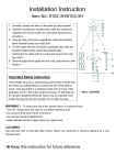
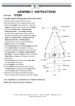
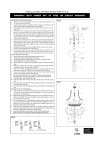
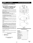
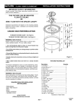
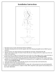
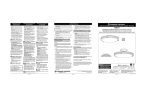
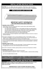
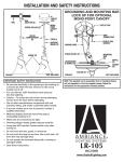
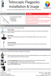
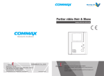
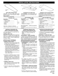
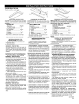
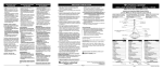
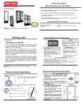
SATURN
INSTALLATION INSTRUCTIONS
FLUSH / SEMI FLUSHMOUNT
IMPORTANT SAFETY INFORMATION
(Protect yourself. Read these instructions carefully and save
them for future reference.)
THIS FIXTURE CAN BE MOUNTED
FLUSH TO CEILING
OR
SEMI- FLUSH WITH THE SPACER CANOPY
Hardware requirements will depend on the mounting method.
Determine fixture location, orientation and mounting method,
before proceeding.
CHOOSE YOUR PREFERRED OPTION
TO MOUNT FIXTURE FLUSH - See Figure 2.
TO MOUNT FIXTURE SEMI-FLUSH - See Figure 4.
WARNING: RISK OF SHOCK
Electric current can cause painful shock or serious injury
unless handled properly. For your safety, always:
• Turn off electrical power at fuse or circuit breaker box
before wiring fixture to the power supply.
• Turn off the power when you change lamps or perform other
maintenance.
• Ground the fixture to avoid potential electric shocks and to
ensure reliable starting.
Figure 1
• Double-check all connections to be sure they are tight and
correct.
• Wear rubber-soled shoes and work on a sturdy wooden
ladder.
This fixture is designed for use in a circuit protected by a fuse
or circuit breaker and to be installed in accordance with local
electrical codes. If you are unsure about your wiring, consult a
qualified electrician or local electrical inspector, and check your
local electrical code.
WARNING: RISK OF INJURY
Some metal parts in the fixture may have sharp edges. To prevent cuts and scrapes, wear gloves when handling the parts.
Account for small parts and destroy packing material, as these
may be hazardous to children.
REQUIRED TOOLS FOR INSTALLATION
(NOT INCLUDED)
. Safety glasses
. Ruler / Tape measure
. Pliers
. Pencil
. Phillips screwdriver
. Adjustable wrench
Lamps Included.
All Mounting Hardware Included.
page 1
FIXTURE PACKING LIST
Description
Quantity
1) Crossbar * ..................................................... 1
2) Screw #8-32 x 1" * .......................................... 2
3) Wire Nuts * ..................................................... 3
4) Green ground screw * ................................... 1
5) 1/8IP x 1¾ " Nipple * ...................................... 1
6) 1/8IP Hexnut * ................................................ 8
7) Lock Washer * ................................................ 7
8) Canopy * ........................................................ 2
9) 1/8IP x 3/8" Nipple * ....................................... 6
10) Spacer Pipe * ............................................... 3
11) Standoff * .................................................... 3
12) Pan ............................................................... 1
13) Diffuser ........................................................ 1
14) Metal Ring .................................................... 1
15) L-Angle ......................................................... 3
16) Finial Cap (large)* ....................................... 2
17) Finial Cap (small) * ...................................... 3
18)1/8IP x 1-3/8’’ Nipple* ................................... 1
* Contained in Parts Packs
U21235T
10/03
1. Remove fixture components and parts pack(s). Check
that all parts are included. See Figure 1.
2. Disassemble the fixture by unscrewing the three finial caps
and removing the “L” angles, metal ring and diffuser.
3. Attach crossbar to junction box with the (2) #8 x 1 machine
screws. (head of green screw should face downward.)
4. Screw the 1/8IP x 1½" nipple into the center hole of the
crossbar about ¼ inch. See Figure 3.
WIRING AND FIXTURE OPERATION
CAUTION: Connect fixture to supply wires rated for at
least 90° (194°F). Do not use fixture on dimming circuits.
Figure 2
FIGURE 2: TO FLUSH MOUNT FIXTURE
Follow steps 5A à 7A.
5A. With the power off, connect the copper ground wire from
the junction box to the fixture by wrapping it under the head
of the green ground screw and tightening the screw. (If house
wiring includes no ground wire consult your local electrical
code for approved methods). See Figure 3.
6A. Use wirenuts to connect the black fixture wire(s) to the
black power supply wire and white fixture wire(s) to white
power supply wire. See Figure 3 .
FOR PROPER CONNECTION, PLACE WIRENUT OVER
WIRES, TWIST CLOCKWISE UNTIL TIGHT.
7A. Place the fixture pan over the nipple extending from the
crossbar previously mounted to the junction box.
See Figure 3.
8A. Place a lock washer and hexut onto nipple. Hold the pan
against the ceiling and tighten the nut until the pan is secure.
Proceed to Step 12.
Figure 3
page 4
WIRING AND FIXTURE OPERATION
CAUTION: Connect fixture to supply wires rated for at least 90°
(194°F). Do not use fixture on dimming circuits.
FIGURE 4: TO SEMI-FLUSH MOUNT FIXTURE
Follow steps 5B to 11B.
5B. Pre-assemble the three spacer pipes by threading a
1/8IP x 3/8" nipple into both ends of each pipe about ¼".
See Figure 5.
6B. Insert each assembled pipe into one of three outer holes
of one canopy, place a lock washer and hexnut onto each
nipple and tighten. Repeat assembly using other canopy.
See Figure 5.
Figure 4
7B. Gather the black, white and fixture wires together and
feed them through one of the spacer pipes. Feed the green
ground wire through another spacer pipe until the lower
canopy rests on the pan.
8B. Thread a finial cap onto the remaining 1/8IP x 1-3/8"
nipple. Push the nipple through the center holes of the
canopy and pan then secure the components with a lock
washer and hexnut. See Figure 5.
9B.With the power off, hold the fixture firmly and connect the
ground wire from the fixture to the junction box, by wrapping
them under the head of the green ground screw and securing them to the crossbar. (If house wiring includes no ground
wire consult your local electrical code for approved methods). See Figure 3.
10B. Use wirenuts to connect the black fixture wire(s) to the
black power supply wire and white fixture wire(s) to white
power supply wire. See Figure 3 .
FOR PROPER CONNECTION, PLACE WIRENUT OVER
WIRES, TWIST CLOCKWISE UNTIL TIGHT.
11B. Place upper canopy over the nipple extending from the
crossbar previously mounted to the junction box and thread a
finial cap in place until the canopy is secure.
12. Insert the lamps(s) and reinstall the diffuser, metal ring , “L”
angles and finial caps.
13. Turn on electricity at fuse or circuit breaker box .
Figure 5
page 6
FLUORESCENT LIGHTING
TROUBLESHOOTING GUIDE
GUIDE DE DÉPANNAGE POUR
L’ÉCLAIRAGE FLUORESCENT
GUÍA DE AYUDA PARA
ILUMINACIÓN FLUORESCENTE
Fluorescent lighting installations provide service
for many years with little or no maintenance except for routine cleaning and re-lamping. If a
malfunction does occur, use the guide below to
diagnose and correct the problem. If further assistance is required, contact:
Consumer Products Customer Service at
(800) 748-5070
Les installations d’éclairage fluorescent procurent
un rendement fiable presque sans entretien durant plusieurs années sauf le dépoussiérage et
le remplacement des lampes. En cas de défectuosité, se référer au guide suivant afin d’en trouver la cause et corriger le problème. Pour de
l’aide, contacter le Service à la Clientèle
(Consumer Products Customer Service) au
numéro (800) 748-5070.
La instalación de iluminación fluorescente provee
de servicio por muchos años con poco o ningún
mantenimiento excepto por la limpieza rutinaria y
cambio de lámparas. Si llega a ocurrir una falla,
use la siguiente guía para diagnosticar y corregir
el problema. Si requiere de más asistencia,
comuníquese a: Consumer Products Customer
Service al (800) 748-5070.
If fixture “hums”:
Si le ballast “bourdonne”:
1. Verify ballast is securely fastened to ballast hous- 1. Vérifier s’il est fixé solidement au boîtier.
ing.* All magnetic ballasts will “hum” slightly.
2. Vérifier si la mise à terre est effectuée correcte2. Verify fixture is grounded properly.
ment.
3. Allow fixture to remain on continuously for 48 to 3. Faire fonctionner l’appareil durant 48 à 72 heures.
72 hours. This allows for proper “seasoning” of
Ceci favorise l’acclimatation du ballast.
the ballast.
Si la lampe n’allume pas:
If lamp(s) will not operate:
1. S’assurer que chaque lampe est bien insérée
1. Make sure all lamps are properly seated in
dans la douille.
socket.
2. Remplacer toute lampe défectueuse.
2. Replace defective lamp(s).
3. Réinsérer ou changer le démarreur (à préchauf3. Reseat or change starter (preheat only).
fage seulement).
4. Verify that fixture is wired properly.
4. Vérifier le raccordement de l’appareil.
5. Verify that fixture is grounded. (All fluorescent 5. Vérifier que la mise à terre est bien effectuée, (la
fixtures must be grounded.)
mise à terre est essentielle).
If lamp(s) is/are slow or erratic when starting:
1. Check to see if fixture is properly grounded.
2. Check ballast label to verify that correct lamp is
installed in fixture.
3. Verify that fixture is wired properly.
4. Check for low voltage supply.
5. Make sure all lamps are properly seated in sockets.
S’il y a un allumage lent ou irrégulier:
1. Vérifier la mise à terre de l’appareil.
2. Vérifier l’étiquette du ballast afin de confirmer la
compatibilité des lampes utilisées.
3. Vérifier le raccordement de l’appareil.
4. Vérifier la possibilité d’une baisse de tension.
5. S’assurer que chaque lampe est bien insérée
dans la douille.
If lamp(s) blink, flicker or “snake”:
1. Turn fixture on and off several times at 30
minute intervals.
2. Check ambient temperatures and, if needed,
change ballast rated for conditions below 50°F.
3. Check for fans or air conditioning blowing
across lamps.
4. Check wiring connections.
5. Allow fixture to remain on for 24 to 48 hours;
this will “season” the lamp.
6. Check supply voltage.
Si la lampe clignote, oscille:
1. Éteindre et rallumer l’appareil plusieurs fois aux
30 minutes.
2. Vérifier la température ambiante et au besoin
utiliser un ballast pour températures inférieures à
50° F.
3. Vérifier la présence de ventilateur ou climatisation à proximité des lampes.
4. Vérifier chaque connexion.
5. Faire fonctionner l’appareil durant 24 à 48 heures
afin d’acclimater la lampe.
6. Vérifier la tension d’alimentation.
If there is reduced light output:
1. Check for ambient temperature significantly S’il y a diminution du flux lumineux:
above or below 77° F.
1. Vérifier la température ambiante au cas où bien
2. Check for fans or air conditioning blowing
inférieure ou supérieure à 77°F.
across lamps.
2. Vérifier la présence de ventilateur ou climatisa3. Check wiring connections.
tion à proximité des lampes.
3. Vérifier les connexions électriques.
If there is radio interference:
En cas d’interférence radio ou autre:
1. Move electronics at least 10 feet from lamps.
2. Install radio interference filter.
1. Éloigner tout appareil électronique à au moins
3. Improve equipment grounding or install
10 pieds des lampes.
shielded grounded radio antenna.
2. Installer un écran antiparasites.
3. Améliorer la mise à terre de l’équipement ou insIf lamps repeatedly cycle on and off:
taller une antenne radio avec mise à terre blindée.
1. Check ballast label for correct lamp and verify
that correct lamp is installed in the fixture.
En cas de cycle répétif marche-arrêt:
2. Check wiring connections.
1. Vérifier si les lampes sont conformes aux indica3. Check supply voltage.
tions sur le ballast.
4. Check for high ambient temperatures,
2. Vérifier les connexions électriques.
ventilate, or suspend fixture.
3. Vérifier la tension de l’alimentation.
4. Vérifier la température ambiante, au besoin ventiler ou suspendre l’appareil.
page 8
Si la luminaria emite sonidos:
1. Verifique si la balastra está firmemente sujeta al gabinete
de la luminaria. *Todas las balastras magnéticas “emiten
sonidos” ligeramente.
2. Verifique si la luminaria está haciendo tierra correctamente.
3. Permita a la luminaria permanecer encendida por 48 a
72 horas, ésto va a aclimatar a la lámpara. Esto permite
que la balastra se “acondicione” adecuamente.
Si la(s) luminaria(s) no operan:
1. Asegúrese que todas las lámparas estén bien colocadas
en los sockets.
2. Reemplace lámparas fundidas.
3. Vuelva a encender o cambiar el arrancador (sólo para
balastras magnéticas).
4. Revise si la luminaria está alambrada apropiadamente.
5. Verifique que la luminaria está haciendo tierra (todas
las luminarias fluorescentes deben hacer tierra).
Si la(s) luminaria(s) es/son lenta(s) o falla(n) al encender:
1. Revise si la luminaria está haciendo tierra.
2. Revise la etiqueta de la balastra para verificar que la
lámpara correcta está siendo instalada en la luminaria.
3. Verifique que la luminaria está alambrada apropiadamente.
4. Revise el nivel de voltaje.
5. Asegúrese que todas las lámparas estén bien
colocadas en los sockets.
Si la(s) luminaria(s) parpadean, titilan, o vibran:
1. Apague y prenda la luminaria varias veces en intervalos de 30 minutos.
2. Revise la temperatura ambiente y si se
necesita, cambia a una balastra apropiada para
condiciones menores de 50°F (10°C).
3. Revise si afectan el aire acondicionado o abanicos a
las lámparas.
4. Revise conexiones de alambrado.
5. Permita a la luminaria permanecer encendida por 24 a
48 horas, ésto va a aclimatar a la lámpara.
6. Revise el voltaje.
Si hay salida de iluminación reducida:
1. Revise que la temperatura ambiente sea
significativamente arriba o abajo de 77°F (25°C).
2. Revise si afectan el aire acondicionado o abanicos a
las lámparas.
3. Revise conexiones de alambrado.
Si hay interferencia de radio:
1. Mueva los aparatos electrónicos al menos 10 pies (3m)
lejos de las luminarias.
2. Instale un filtro para interferencias de radio.
3. Mejore el equipo para hacer tierra o instale una antena
de radio protegida para hacer tierra.
Si las lámparas se prenden y apagan repetidamente:
1. Revise la etiqueta de la balastra para verificar que la
lámpara correcta está siendo instalada en la luminaria.
2. Revise conexiones de alambrado.
3. Revise el voltaje.
4. Revise temperatura ambiente alta, ventile o suspenda
la luminaria.