1
INSTALLATION INSTRUCTIONS
CAUTION: MAKE SURE POWER IS SWITCHED OFF AT SERVICE PANEL BEFORE
STARTING INSTALLATION.
SECTION 1
Preparing the Exhaust Fan
1. Unpack fan from the carton and confirm that all pieces are present. In addition to the
exhaust fan you should have:
POWER UNITS
KITS
1 - Blower
1 - Blower
1 - Mounting Bracket
1 - Mounting Bracket
1 - Instruction/Safety Sheet 1 or 2 - Room Inlets with Grill
1 - Instruction/Safety Sheet
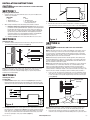
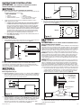
Figure 3
6" Inline Kits
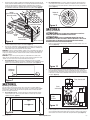
2. Determine the location of the round intake assembly. Cut an 8" round hole through the
ceiling material being careful not to damage any electrical wires or other utilities (Figure 4).
2. When selecting fan mounting location, the following criteria should be considered:
a) Mounting to minimize noise generated by fan operation: Mounting the fan as far as
possible from the intake point will minimize fan operating noise from being transmitted
back through the duct work. If the fan is to be used as a booster for moving the air
between two rooms, a central point along the duct may be optimal. Insulated flexible
type duct work (recommended for all bathroom exhaust applications) will result in
much quieter operation. It is recommended that a minimum 8' of insulated flexible
ducting be used between any exhaust grill and fan for low noise level.
Joist
b) Service accessibility: Fan location should allow sufficient access for service.
SECTION 2
Installing the Fan
1. Attach the included mounting bracket to the wall stud or ceiling joist. Connect the fan to
the moutning bracket using the included screws (Figure 1).
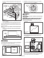
Figure 4
SECTION 4
Ducting
CAUTION: ALL DUCTING MUST COMPLY WITH LOCAL AND NATIONAL
BUILDING CODES.
NOTE: The ducting from this fan to the outside of the building has a strong effect on the air
flow, noise and energy use of the fan. Use the shortest, straightest duct routing possible
for best performance, and avoid installing the fan with smaller ducts than recommended.
Insulation around the ducts can reduce energy loss and inhibit mold growth. Fans installed
with existing ducts may not achieve their rated air flow.
Joist/Stud
NOTE: Insulated ducting is required for bathroom exhaust applications, where ducting passes
through unconditioned space or where noise is a factor. Failure to use insulation could result in
excessive condensation buildup within the duct, and undesirable sound levels within the room.
Duct runs should have as few bends as possible.
Figure 1
Bracket
NOTE: Fan mounting can be at any point along the duct and in any angle, however, vertical
mounting is recommended to reduce condensation buildup in the fan. If a horizontal
installation is necessary and condensation buildup may pose a problem, wrap insulation
around the fan to minimize buildup.
NOTE: Flexible insulated ducting may be used where allowed by local code. For the quietest
possible installations, it is recommended a minimum of 8' of insulated flexduct be used
between any exhaust grill and fan. When using flexible type duct work, duct should be
stretched as tight and straight as possible. Failure to do so could result in dramatic loss of
system performance. Flexible duct should be connected to the fan with screw clamps or duct
tape. All connections should be as airtight as possible to maximize system performance.
1.
SECTION 3
Installing the Inlets
Connect one end of the ducting (not included) to the room level collar/damper and the
other end to the “Y” transition. Secure both ends in place using tape or a screw clamp
to create as air tight a seal as possible. Repeat this step for the other room level grill
housing (Figure 5).
4" Inline Kits
Exhaust to Wall/
Roof Cap
1a. New Constructions: Using the gauge on the fan’s housing (Figure 2), line up housing so
that it will be flush with the finished ceiling or wall. Position the fan so that the tabs rest flat
against the joist or stud and secure with four nails (not provided) to ensure proper installation.
Fan
“Y” Transition
Housing
Figure 5
Figure 2
1b. Existing Constructions: Position housing against the joist or stud and trace an outline of
the housing onto the ceiling/wall material (Figure 3). Set housing aside and cut opening,
being careful not to cut or damage any electrical or other hidden utilities. Place housing
next to the joist or stud and insure that it is flush with the finished ceiling. Secure with
four nails (not provided) to ensure proper installation (Figure 2).
A210952017 Rev. F 10-15
Housing
Ducting
NOTE: Units that include only one collar do not utilize the “Y” transition. Follow the same
instructions as in step 1, except connect the one end of the ducting directly to the fan.
2.
Ensure duct joints and exterior penetrations are sealed with caulk or other similar
material to create an air-tight path to minimize building heat loss or gain and to reduce
www.airkinglimited.com
2 of 8