1
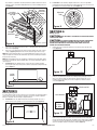
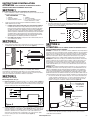
the potential for condensation. Place/wrap insulation around duct and/or fan in order to
minimize possible condensation buildup within the duct, as well as building heat loss or
gain (Figure 6).
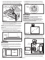
1b. 6" Inline Kits: Locate the damper adjustment knob in the center of the grill. While
pushing inward on the knob, twist the knob to adjust the damper to uncover as much of
the opening as is necessary to balance the system (Figure 9).
Roof Cap*
(with built-in
damper)
Insulation*
(place around and
over inlet
Adjustment
Knob
Keep duct
runs short
Inlet
Figure 9
SECTION 6
Seal gaps
around Inlet
Wiring the Fan
Round
Duct*
CAUTION: MAKE SURE POWER IS SWITCHED OFF AT SERVICE PANEL BEFORE
STARTING INSTALLATION.
Seal duct joints
with tape
CAUTION: ALL ELECTRICAL CONNECTIONS MUST BE MADE IN ACCORDANCE
Figure 6
*Purchase separately
3.
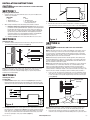
Connect one end of the ducting to the top of the “Y” transition and the other end to the
intake of the fan (Figure 5).
4.
Connect one end of the ducting to the exhaust of the fan and the other end to a wall or
ceiling cap (Figure 5). Always duct the fan to the outside through a wall or roof cap.
WITH LOCAL CODES, ORDINANCES, OR NATIONAL ELECTRICAL CODE. IF YOU ARE
UNFAMILIAR WITH METHODS OF INSTALLING ELECTRICAL WIRING, SECURE THE
SERVICES OF A QUALIFIED ELECTRICIAN.
1.
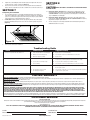
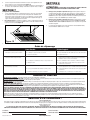
Remove the screws securing the terminal box cover plate located on the side of the
motor (Figure 10).
NOTE: When using insulated flex duct, it is recommended that the inner vinyl core be screw
clamped or taped to the inlet and outlet and that the vapor barrier surrounding the insulation
be taped to the fan housing.
NOTE: When attaching flex duct to the collar/damper combination and an immediate elbow is
necessary, be certain that the elbow is installed with a “soft” bend to allow damper blades to
operate properly.
5.
6" Inline Kits: Once the ducting has been connected to the room intake assembly,
press the grill up into the previously cut hole until the spring loaded ceiling holders snap
in place (Figure 7).
Screws
Figure 10
Ceiling
Holders
2.
Run wiring from an approved wall switch carrying the appropriate rating. One neutral
(white) one hot (black lead connected to the switch) and one ground (green or bare
wire). Loosen the wire strain relief bar and run the wires through the wire access
nut and the strain relief, making sure to leave enough wire to make all electrical
connections (Figure 11).
Figure 7
Wire Access Nut
SECTION 5
Balancing the System
For systems with more than one inlet, it may be nesseccary to balance the air flow depending
on the location of the inlets. The system can be balance at room level using the adjustable
dampers located inside the inlet housing. To adjust the damper:
Strain Relief Bar
1a. 4" Inline Kits: Locate the damper inside of the inlet housing and slide it to cover or
uncover as much of the opening as is necessary to balance the system (Figure 8).
G - Ground
B - Black
W - White
Damper
G
B
W
Figure 11
3.
Figure 8
A210952017 Rev. F 10-15
Insert the white wire from the house into the terminal strip with the white wire and
tighten using a small regular screwdriver. Insert the black wire from the wall switch
into the terminal strip with the black wire and tighten using a small regular screwdriver.
Insert the green (or bare) ground wire from the house into the terminal strip with the
green wire and tighten using a small regular screwdriver (Figure 11).
www.airkinglimited.com
3 of 8