1
Renovent Excellent 300/400 (Plus)
INSTALLATIEVOORSCHRIFTEN
(Nederlands)
INSTALLATION INSTRUCTIONS
(English)
INSTALLATIONSVORSCHRIFTEN
CONSIGNES D'INSTALLATION
(Deutsch)
(Francais)
WWW.BRINKAIRFORLIFE.NL
Installatievoorschriften
Warmteterugwinapparaat
Renovent Excellent 300/400 (Plus)
BEWAREN BIJ HET TOESTEL
Gebruik van dit toestel is niet toegestaan door personen, inclusief kinderen, met verminderde geestelijke vermogens, ernstige
lichamelijke beperkingen of een gebrek aan ervaring en kennis, tenzij ze onder toezicht staan of instructies hebben gekregen hoe
het toestel te gebruiken van een persoon die verantwoordelijk is voor hun veiligheid.
Op kinderen moet zodanig toezicht worden gehouden dat zij gegarandeerd niet met het toestel spelen.
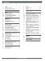
Inhoudsopgave
1
1.1
1.2
Levering......................................................... 1
Leveromvang.................................................. 1
Accessoires Renovent Excellent .................... 2
9
9.1
9.2
Onderhoud .................................................. 25
Filter reinigen................................................ 25
Onderhoud.................................................... 26
2
Toepassing.................................................... 5
10
10.1
Elektrische schema.................................... 28
Aansluitschema ............................................ 28
3
3.1
3.2
3.2.1
3.2.2
3.3
Uitvoering......................................................
Technische informatie.....................................
Aansluitingen en afmetingen ..........................
Renovent Excellent rechter uitvoering..........
Renovent Excellent linker uitvoering ............
Opengewerkt toestel.......................................
6
6
8
8
9
10
4
4.1
4.2
4.3
4.4
Werking .........................................................
Omschrijving...................................................
Bypassvoorwaarden.......................................
Vorstbeveiliging ..............................................
Renovent Excellent Plus uitvoering................
11
11
11
11
11
5
5.1
5.2
5.3
5.4
5.5
5.5.1
5.5.2
5.5.3
Installeren......................................................
Installeren algemeen ......................................
Plaatsen toestel..............................................
Aansluiten condensafvoer ..............................
Aansluiten kanalen .........................................
Elektrische aansluitingen................................
Aansluiting van de netstekker.......................
Aansluiten van de standenschakelaar..........
Aansluiting eBus cq OpenTherm connector .
12
12
12
12
12
14
14
14
14
6
6.1
6.2
6.2.1
6.2.2
6.2.3
6.3
6.4
6.5
Display weergave .........................................
Algemene verklaring bedieningspaneel..........
Bedrijfssituatie ................................................
Status systeemventilator ..............................
Weergave luchtdebiet...................................
Meldingstekst bij bedrijfssituatie...................
Instelmenu......................................................
Uitleesmenu....................................................
Servicemenu...................................................
15
15
16
16
16
17
18
19
20
7
7.1
7.2
7.3
7.4
In werking stellen .........................................
In- en uitschakelen toestel..............................
Instellen luchthoeveelheid ..............................
Overige instellingen installateur......................
Fabrieksinstelling............................................
21
21
22
22
22
8
8.1
8.2
Storing ........................................................... 23
Storingsanalyse.............................................. 23
Displaycodes .................................................. 23
11
11.1
11.2
11.2.1
11.2.2
Elektrische aansluitingen accessoires.....
Aansluitingen connectoren ...........................
Aansluitvoorbeelden standenschakelaar......
6WDQGHQVFKDNHODDUPHW¿OWHULQGLFDWLH.........
'UDDGOR]HDIVWDQGVEHGLHQLQJ]RQGHU¿OWHU
indicatie) .....................................................
11.2.3 ([WUDVWDQGHQVFKDNHODDUPHW¿OWHULQGLFDWLH
11.2.4 Extra standenschakelaar draadloze afstand- bediening.........................................
11.3
Koppelen middels eBus; alle toestellen gelijke luchtdebiet.............................................
11.4
Aansluiten RH(vochtigheid)-sensor..............
11.5
Bedradingsschema aansluiting naverwarmer (alleen bij Renovent Excellent Plus)......
11.6
Aansluitvoorbeeld aardwarmtewisselaar (alleen mogelijk bij Renovent Excellent Plus)...
11.7
Aansluiten extern schakelcontact (alleen
mogelijk bij Renovent Excellent Plus)...........
11.8
Aansluiten op 0 - 10 V. ingang (alleen mogelijk bij Renovent Excellent Plus)....................
29
29
30
30
30
30
30
31
31
32
33
34
35
12
12.1
12.2
Service......................................................... 36
Exploded view .............................................. 36
Service artikelen........................................... 36
13
Instelwaarden.............................................. 38
Conformiteitsverklaring................................. 40
Levering
Hoofdstuk 1
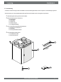
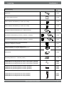
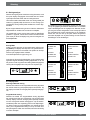
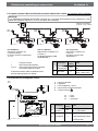
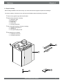
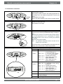
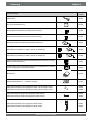
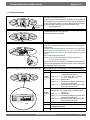
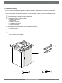
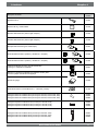
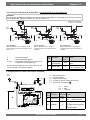
1.1 Leveromvang
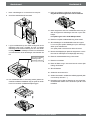
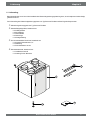
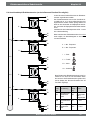
Controleer voordat men begint met de installatie van het warmteterugwintoestel of deze compleet en onbeschadigd is geleverd.
De leveromvang van het warmteterugwintoestel type Renovent Excellent omvat de volgende componenten:
c Warmteterugwintoestel type Renovent Excellent
d Muurophangbeugelset bestaande uit:
[RSKDQJVWULSV
[VWRRWGRSMHV
[UXEEHUVWULS
[UXEEHUHQULQJHQ
[PRQWDJHKDQGOHLGLQJ
e PVC-Condensafvoeraansluiting bestaande uit:
[NXQVWVWRIVFKURHIZDUWHO´
[DIGLFKWULQJ
[39&OLMPDDQVOXLWVWXNPP
f Documentatieset bestaande uit:
[LQVWDOODWLHYRRUVFKULIW
[EHZRQHUVLQVWUXFWLH
2
1
3
Renovent Excellent 300/400
4
1
Hoofdstuk 1
Levering
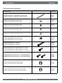
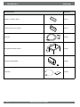
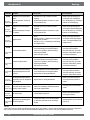
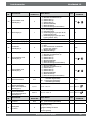
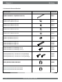
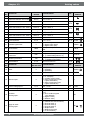
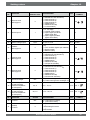
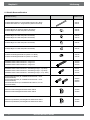
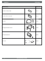
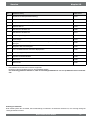
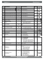
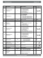
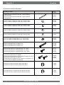
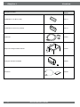
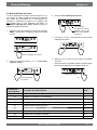
1.2 Accessoires Renovent Excellent
Artikelomschrijving
Artikelcode
Kunststof buis Ø160 mm / Lengte 2025mm (6 stuks in doos)
Kunststof buis Ø180 mm / Lengte 2025 mm (4 stuks in doos)
200141
200131
Kunststof bocht 90° Ø160 mm (8 stuks in doos)
Kunststof bocht 90° Ø180 mm (8 stuks in doos)
200144
200132
Kunststof bocht 45° Ø160 mm (8 stuks in doos)
Kunststof bocht 45° Ø180 mm (8 stuks in doos)
200145
200133
Kunststof bocht 30° Ø180 mm (8 stuks in doos)
200134
Kunststof bocht 15° Ø180 mm (8 stuks in doos)
200135
Kunststof koppelstuk Ø160 mm (1 stuks in doos)
Kunststof koppelstuk Ø180 mm (1 stuks in doos)
200148
200138
Akoestische slang Ø150 mm / Lengte 10 m
Akoestische slang Ø160 mm / Lengte 10 m
Akoestische slang Ø180 mm / Lengte 10 m
207750
207760
207780
Akoestische slang Ø150 mm / Afgewerkte lengte 1 m (1 stuks)
Akoestische slang Ø160 mm / Afgewerkte lengte 1 m (1 stuks)
Akoestische slang Ø180 mm / Afgewerkte lengte 1,5 m (1 stuks)
207751
207761
207782
Aansluitset Ø150 mm (2x akoest. slang 1 m met aansluitmateriaal)
Aansluitset Ø160 mm (2x akoest. slang 1 m met aansluitmateriaal)
Aansluitset Ø180 mm (2x akoest. slang 1,5 m met aansluitmateriaal)
648550
648560
648570
Elektrische naverwarmer Excellent 300 Ø 160mm
Elektrische naverwarmer Excellent 400 Ø 180mm
310630
310650
Elektrische (extra)voorverwarmer Excellent 300 Ø 160mm
Elektrische (extra)voorverwarmer Excellent 400 Ø 180mm
310640
310660
2
Renovent Excellent 300/400
Levering
Hoofdstuk 1
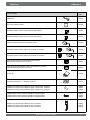
Artikelomschrijving
Artikelcode
Splitter RJ12
510472
CO2-sensor opbouw uitvoering
511396
Zender draadloze afstandbediening 2 standen (incl. batterij)
531785
Zender draadloze afstandbediening 4 standen (incl. batterij)
531786
Ontvanger draadloze afstandbediening (t.b.v. batterij uitvoering)
531787
Set draadloze afstandbediening 2 standen (1 zender & 1 ontvanger)
531788
Set draadloze afstandbediening 4 standen (1 zender & 1 ontvanger)
531789
6WDQGHQVFKDNHODDUZLWLQERXZ]RQGHU¿OWHULQGLFDWLH
Levering incl. inzetplaat en afdekraam
540214
6WDQGHQVFKDNHODDUZLWPHW¿OWHULQGLFDWLHLQERXZ
modulaire aansluiting. Levering incl. inzetplaat en afdekraam
540262
Bedienmodule
510490
Set foamringen Ø150 mm ÖØ160 mm (4 stuks)
217000
Ventilatiedakdoorvoer D150 (geschikt voor toevoer, onder de pannen; geïsoleerd)
Ventilatiedakdoorvoer D160 (geschikt voor toevoer, onder de pannen; geïsoleerd)
Ventilatiedakdoorvoer D180 (geschikt voor toevoer, onder de pannen; geïsoleerd)
648620
648630
648680
Ventilatiedoorvoer gevel D150 (geschikt voor toevoer, geïsoleerd)
Ventilatiedoorvoer gevel D160 (geschikt voor toevoer, geïsoleerd)
Ventilatiedoorvoer gevel D180 (geschikt voor toevoer, geïsoleerd)
648690
648640
648690
Ventilatiedakdoorvoer D150 (geschikt voor afvoer; geïsoleerd)
Ventilatiedakdoorvoer D166 (geschikt voor afvoer; geïsoleerd)
Ventilatiedakdoorvoer D180 (geschikt voor afvoer; geïsoleerd)
648610
648700
648670
Renovent Excellent 300/400
3
Hoofdstuk 1
Levering
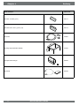
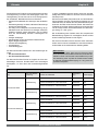
Artikelomschrijving
Artikelcode
)LOWHUVHW[)¿OWHUVWXNV
531771
Filterset 1x G3 & 1x F7 (2 stuks)
531773
RH-sensor
310657
Montagestoel Excellent 300/ 400
217035
Enthalpie warmtewisselaar
532059
Servicetool
531962
4
Renovent Excellent 300/400
Toepassing
Hoofdstuk 2
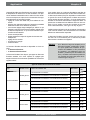
De Brink Renovent Excellent is een ventilatieunit met warmteterugwinning met een hoog rendement, een maximale ventilatiecapaciteit van 300 of 400 m3/h en energiezuinige ventilatoren. Kenmerken Renovent Excellent:
WUDSOR]H LQVWHOEDDUKHLG OXFKWKRHYHHOKHGHQ YLD EHGLHQLQJVpaneel.
GHDDQZH]LJKHLGYDQ¿OWHULQGLFDWLHRSKHWWRHVWHOHQGHPRJHOLMNKHLGYRRU¿OWHULQGLFDWLHRSGHVWDQGHQVFKDNHODDU
HHQJHKHHOQLHXZHLQWHOOLJHQWHYRUVWUHJHOLQJGLHHUYRRU]RUJW
dat het toestel ook bij lage buitentemperaturen optimaal blijft
functioneren en, indien noodzakelijk, ook de standaard gemonteerde voorverwarmer inschakelt.
ODDJJHOXLGVQLYHDX
VWDQGDDUGYRRU]LHQYDQDXWRPDWLVFKZHUNHQGHE\SDVVNOHS
FRQVWDQWÀRZUHJHOLQJ
HQHUJLH]XLQLJ
KRRJUHQGHPHQW
In dit installatievoorschrift wordt zowel de standaard Renovent
Excellent als de Renovent Excellent Plus besproken.
De Renovent Excellent (Plus) is leverbaar in een linker of een
UHFKWHUXLWYRHULQJ%LMHHQOLQNHUXLWYRHULQJ]LWWHQGH¿OWHUVOLQNV
DFKWHUGH¿OWHUGHXUELMHHQUHFKWHUXLWYRHULQJ ]LWWHQGH¿OWHUV
UHFKWV DFKWHU GH ¿OWHUGHXU 'H SRVLWLH YDQ GH OXFKWNDQDOHQ LV
bij deze twee uitvoeringen verschillend! Voor juiste positie aansluitkanalen en afmetingen zie §3.2.1 resp. §3.2.2.
Bij bestelling van een toestel altijd het juiste type codering opgeven; ombouwen naar een andere uitvoeringsvariant is naderhand niet mogelijk.
De Renovent Excellent wordt af fabriek geleverd met een 230V.
netstekker en een aansluiting voor een zwakstroomstandenschakelaar aan de buitenzijde van het toestel.
De Renovent Excellent 300/400 is leverbaar in twee types:
GH³5HQRYHQW([FHOOHQW´
GH³5HQRYHQW([FHOOHQW3OXV´
De Renovent Excellent Plus heeft t.o.v. standaard Renovent
Excellent een uitgebreidere regelprint waardoor deze meer
aansluitmogelijkheden heeft.
Let op: Wanneer een Renovent Large wordt vervangen
door een Renovent Excellent denk er hierbij aan
GDWGHSRVLWLHYDQGHNDQDOHQ³8LWZRQLQJ´HQ³9DQ
EXLWHQ´DIZLMNHQGYDQHONDDULVDOOHHQELMW\SH
& 3/1) Controleer positie van deze kanalen goed
aan de hand van de aansluittekeningen §3.2.1 en
§3.2.2.
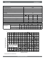
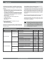
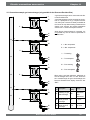
Uitvoeringstypes Renovent Excellent 300/400
Type
Uitvoering L of R
Linker uitvoering
Positie luchtkanalen
Voeding
Type codering
4 boven aansluitingen
Netstekker
4/0 L
2 boven aansluitingen & 2 onder aansluitingen
Netstekker
2/2 L
3 boven aansluitingen & 1 onder aansluiting
Netstekker
3/1 L
4 boven aansluitingen
Netstekker
4/0 R
2 boven aansluitingen & 2 onder aansluitingen
Netstekker
2/2 R
3 boven aansluitingen & 1 onder aansluiting
Netstekker
3/1 R
4 boven aansluitingen
Netstekker
4/0 L+
2 boven aansluitingen & 2 onder aansluitingen
Netstekker
2/2 L+
3 boven aansluitingen & 1 onder aansluiting
Netstekker
3/1 L+
4 boven aansluitingen
Netstekker
4/0 R+
2 boven aansluitingen & 2 onder aansluitingen
Netstekker
2/2 R+
3 boven aansluitingen & 1 onder aansluiting
Netstekker
3/1 R+
Renovent Excellent
Rechter uitvoering
Linker uitvoering
Renovent Excellent Plus
Rechter uitvoering
Renovent Excellent 300/400
5
Hoofdstuk 3
Uitvoering
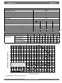
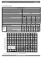
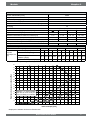
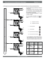
3.1 Technische informatie
Renovent Excellent 300
Voedingsspanning [V/Hz]
230/50
Beschermingsgraad
IP30
Afmetingen (b x h x d) [mm]
677 x 765 x 564
Kanaaldiameter [mm]
Ø150/ Ø160
Uitwendige diameter condensafvoer [mm]
Ø32
Gewicht [kg]
38
Filterklasse
G3 (F7 optioneel voor toevoer)
Ventilatorstand (fabrieksinstelling)
3
Ventilatiecapaciteit [m /h]
50
Toelaatbare weerstand kanalensysteem [Pa]
Opgenomen vermogen (excl. voorverwarmer) [W]
Opgenomen stroom (excl. voorverwarmer) [A]
1
2
3
100
150
225
3-7
11 - 28
26 - 66
56 - 142
9,0 - 9,2
13,7 - 15,2
22,0 - 29,2
46,8 - 66,2
0,104 - 0,107 0,150 - 0,161 0,214 - 0,274 0,403 - 0,578
6
Max. opgenomen stroom (incl. ingeschakelde voorverwarmer) [A]
&RVij
0,368 - 0,374 0,391 - 0,416 0,447 - 0,463
0,505
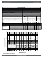
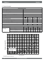
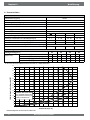
Geluidsvermogen Excellent 300
Ventilatiecapaciteit [m3/h]
Geluidsvermogenniveau Lw (A)
90
150
210
300
Statische druk [Pa]
50
100
50
100
50
100
50
100
Kastuitstraling [dB(A)
30
33
38
38
44
46
50
52
.DQDDO³XLWZRQLQJ´>G%$@
33
34
39
42
45
46
54
54
.DQDDO³QDDUZRQLQJ´>G%$@
44
47
52
55
60
60
67
67
In de praktijk kan door meettoleranties de waarde 1 dB(A) afwijken
400
375
350
325
300
:HHUVWDQGNDQDOHQV\VWHHP>3D@
275
69
250
225
200
175
44
52
150
33
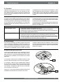
Let op: De vermelde
waarde in de cirkel is het
vermogen (in Watt) per
ventilator
125
100
75
26
23
7
5
0
25
50
75
9HQWLODWRUJUD¿HN5HQRYHQW([FHOOHQW
6
19
12
11
8
0
46
28
23
15
50
25
33
27
100
125
150
175
200
Volumestroom [m3/h]
Renovent Excellent 300/400
225
250
275
300
325
Uitvoering
Hoofdstuk 3
Renovent Excellent 400
Voedingsspanning [V/Hz]
230/50
Beschermingsgraad
IP30
Afmetingen (b x h x d) [mm]
677 x 765 x 564
Kanaaldiameter [mm]
Ø180
Uitwendige diameter condensafvoer [mm]
Ø32
Gewicht [kg]
38
Filterklasse
G3 (F7 optioneel voor toevoer)
Ventilatorstand (fabrieksinstelling)
3
Toelaatbare weerstand kanalensysteem [Pa]
Ventilatiecapaciteit [m /h]
1
2
3
50
100
200
300
3-6
6 - 20
25 - 49
56 - 178
Opgenomen vermogen (excl. voorverwarmer) [W]
8,6
9,5 - 15
29 - 40
72 - 98
Opgenomen stroom (excl. voorverwarmer) [A]
0,10
0,12 - 0,14
0,24 - 0,31
0,51 - 0,7
0,56 - 0,58
0,60 - 0,61
Max. opgenomen stroom (incl. ingeschakelde voorverwarmer) [A]
6
&RVij
0,38
0,45 - 0,40
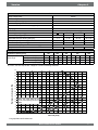
Geluidsvermogen Excellent 400
Ventilatiecapaciteit [m3/h]
Geluidsvermogenniveau Lw (A)
100
Statische druk [Pa]
9
200
40
38
225
80
47
300
100
84
175
400
240
150
Kastuitstraling [dB(A)
29,5 32,5 40,5 41,5 43,5 47,5 51,0 53,0 54,0 54,5 57,0
.DQDDO³XLWZRQLQJ´>G%$@
31,5 34,5 46,5 48,0 48,5 50,0 56,5 57,0 58,0 59,0 60,0
.DQDDO³QDDUZRQLQJ´>G%$@
42,5 47,5 57,0 59,0 60,5 62,5 66,0 68,5 69,5 70,5 71,5
In de praktijk kan door meettoleranties de waarde 1 dB(A) afwijken
400
375
350
325
:HHUVWDQGNDQDOHQV\VWHHP>3D@
300
275
86
250
79
225
200
49
175
150
83
Let op: De vermelde waarde
in de cirkel is het vermogen (in
Watt) per ventilator
125
100
32
58
71
26
40
20
75
51
28
50
25
7
5
0
0
25
225
50
75
100
125
12
17
10
15
150
175
200
22
36
23
19
225
250
275
300
325
350
375
400
425
Volumestroom [m3/h]
9HQWLODWRUJUD¿HN5HQRYHQW([FHOOHQW
Renovent Excellent 300/400
7
Hoofdstuk 3
Uitvoering
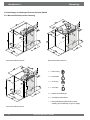
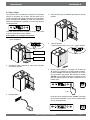
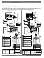
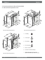
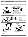
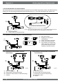
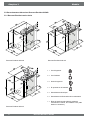
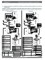
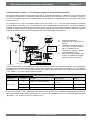
3.2 Aansluitingen en afmetingen Renovent Excellent 300/400
3.2.1 Renovent Excellent rechter uitvoering
Renovent Excellent rechts 2/2
Renovent Excellent rechts 4/0
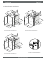
1 = Naar woning
2 = Naar buiten
3 = Uit woning
4 = Van buiten
5 = Elektrische aansluitingen
6 = Aansluiting condensafvoer
7 = Muurophangbeugel (denk hierbij om juiste
plaatsing van de rubberstrip, ringen en dopjes)
Renovent Excellent rechts 3/1
8
Renovent Excellent 300/400
Uitvoering
Hoofdstuk 3
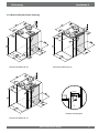
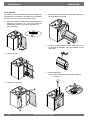
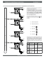
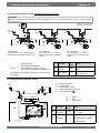
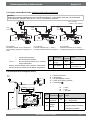
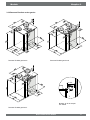
3.2.2 Renovent Excellent linker uitvoering
Renovent Excellent links 2/2
Renovent Excellent links 4/0
10 mm
7
Montage muurophangset
Renovent Excellent links 3/1
Renovent Excellent 300/400
9
Hoofdstuk 3
Uitvoering
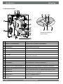
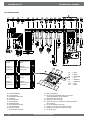
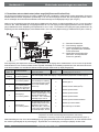
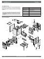
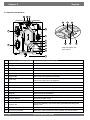
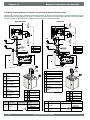
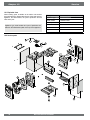
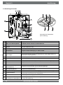
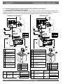
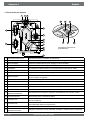
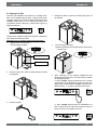
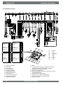
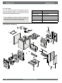
3.3 Opengewerkt toestel
1
2
3
19
18
17
4
13
5
6
7
12
14
15
16
8
9
10
Achteraanzicht displaykap
(Plus uitvoering)
11
1 Service aansluiting
Computeraansluiting voor servicedoeleinden
2 Display en 4 bedieningstoetsen
Interface tussen de gebruiker en regelelektronica
3 Regelprint
Bevat de regelelektronica voor de functionaliteit
4 $IYRHUOXFKW¿OWHU
Filtert luchtstroom uit de woning
5 Voorverwarmer
Warmt buitenlucht op wanneer kans is op invriezen warmtewisselaar
6 Warmtewisselaar
Zorgt voor de warmteoverdracht tussen de toe- en afvoerlucht
7 7RHYRHUOXFKW¿OWHU
Filtert buitenlucht welke woning in gaat
8 Bypassklep
Stuurt de lucht wel of niet over de warmtewisselaar (Deze klep zit bij de 3/1
en 4/0 boven in het toestel)
9 Buitentemperatuurvoeler
Meet de luchttemperatuur van buiten
10 Binnentemperatuurvoeler
Meet de luchttemperatuur uit de woning
11 Condensafvoer
Aansluiting condenswaterafvoer (Set wordt los meegeleverd bij toestel)
12 Afvoerventilator
Voert vervuilde lucht uit de woning naar buiten af
13 Toevoerventilator
Voert verse lucht aan de woning toe
14 Modulaire connector standenschakelaar X2
$DQVOXLWLQJHQQDDUVWDQGHQVFKDNHODDUHYHQWXHHOPHW¿OWHULQGLFDWLH
15 Connector eBus X1
Aansluiting t.b.v. eBus aansturing
16 Connector X15
Bevat de diverse extra stuur in- en uitgangen; alleen bij Plus uitvoering
17 Connector X14
Aansluiting naverwarmer of extra voorverwarmer; alleen bij Plus uitvoering
(bereikbaar na losnemen displaykap)
18 Netsnoer 230 V.
Doorvoer voedingskabel 230 volt
19
Aansluiting naar naverwarmer of extra voor- Doorvoer 230 V. kabel naar naverwarmer of extra voorverwarmer; alleen bij
verwarmer
Plus uitvoering
10
Renovent Excellent 300/400
Werking
Hoofdstuk 4
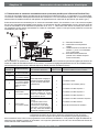
4.1 Omschrijving
Het toestel wordt stekkerklaar geleverd en werkt volautomatisch. De afgevoerde vuile binnenlucht warmt de frisse schone
buitenlucht op. Hierdoor wordt energie bespaard en wordt verse lucht naar de gewenste vertrekken gevoerd.
De regeling is voorzien van vier ventilatiestanden.
Afhankelijk van de aangesloten standenschakelaar kunnen 3of 4 ventilatiestanden worden gebruikt Het luchtdebiet is per
ventilatiestand instelbaar. De constant volume regeling zorgt
ervoor dat de luchtdebiet van de toe- en afvoerventilator onafhankelijk van de kanaaldruk wordt gerealiseerd.
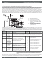
4.2 Bypassvoorwaarden
De standaard gemonteerde bypassklep maakt het mogelijk
frisse buitenlucht toe te voeren, die niet wordt opgewarmd
door de warmtewisselaar. Vooral tijdens zomernachten is het
wenselijk koelere buitenlucht toe te voeren. De warme lucht in
de woning wordt dan zo veel mogelijk vervangen door koelere
buitenlucht.
De bypassklep opent en sluit automatisch wanneer aan een
aantal voorwaarden wordt voldaan (zie onderstaande tabel
voor bypassvoorwaarden).
Met stapnummer 5, stapnummer 6 en stapnummer 7 in het
instelmenu, (zie hoofdstuk 13) kan de werking van de bypassklep worden aangepast.
Bypassklep voorwaarden
Bypassklep open
- De buitentemperatuur is hoger dan 10°C en
- de buitentemperatuur is lager dan binnentemperatuur in woning en
- de temperatuur in de woning is hoger dan de ingestelde temperatuur bij stapnr. 5 in het
instelmenu (standaard ingesteld op 22°C)
Bypassklep gesloten
- De buitentemperatuur is lager dan 10°C of
- de buitentemperatuur is hoger dan de binnentemperatuur in de woning of
- de temperatuur uit de woning is lager dan de ingestelde temperatuur bij stapnr. 5 in het
instelmenu minus de ingestelde temperatuur bij de hysterese (stapnr. 6); deze temperatuur
is af fabriek 20°C (22,0°C minus 2,0°C).
4.3 Vorstbeveiliging
Om invriezen van de warmtewisselaar bij zeer lage buitentemperatuur te voorkomen is de Renovent Excellent uitgevoerd
met een intelligente vorstregeling. Temperatuursensoren meten de temperaturen over de warmtewisselaar en, indien nodig, wordt de voorverwarmer plus eventueel extra aangesloten
voorverwarmer ingeschakeld.
Hierdoor blijft een goede ventilatiebalans, ook bij zeer lage
buitentemperatuur, gehandhaafd. Wanneer bij ingeschakelde
voorverwarmer(s) de wisselaar nog dreigt in te vriezen wordt
er traploos onbalans in het toestel aangebracht.
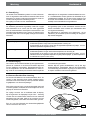
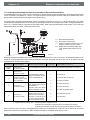
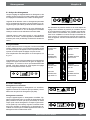
5HQRYHQW([FHOOHQW3OXVXLWYRHULQJ
'H5HQRYHQW([FHOOHQWNDQRRNZRUGHQEHVWHOGDOV³3OXV´XLWvoering. In deze uitvoering zit een andere regelprint gemonteerd met 2 extra connectoren (X14 & X15) met meer aansluitmogelijkheden voor diverse toepassingen.
De 9-polige connector X15 is, zonder dat het toestel open hoeft
te worden gemaakt, bereikbaar aan de achterzijde van de displaykap van de Renovent Excellent
X15
De 2-polige connector X14 is bereikbaar nadat de displayNDSLVORVJHQRPHQ'HGLVSOD\NDSLVELMGH³3OXV´XLWYRHULQJ
voorzien van een tweede wartel. Hierdoor kan een eventueel
aangesloten 230 volt kabel, welke op de connector X14 kan
worden aangesloten, naar buiten het toestel worden gevoerd.
Zie § 11.1 voor meer informatie over de aansluitmogelijkheden
van de connectoren X14 en X15.
Renovent Excellent 300/400
X14
11
Hoofdstuk 5
Installeren
5.1 Installeren algemeen
De installatie van het toestel:
1. Plaatsen van het toestel (§5.2)
2. Aansluiten van de condensafvoer (§5.3)
3. Aansluiten van de kanalen (§5.4)
4. Elektrische aansluiting:
Aansluiten van de netvoeding, standenschakelaar en indien nodig, de OpenTherm/eBus aansluiting (§5.5)
Het installeren dient te geschieden overeenkomstig:
.ZDOLWHLWVHLVHQYHQWLODWLHV\VWHPHQZRQLQJHQ
Kwaliteitseisen gebalanceerde ventilatie woningen
9RRUVFKULIWHQYRRUYHQWLODWLHYDQZRQLQJHQHQZRRQJHERXwen
'HYHLOLJKHLGVEHSDOLQJHQYRRUODDJVSDQQLQJVLQVWDOODWLHV
'HYRRUVFKULIWHQYRRUKHWDDQVOXLWHQRSGHELQQHQULROHULQJLQ
woningen en woongebouwen
(YHQWXHOH DDQYXOOHQGH YRRUVFKULIWHQ YDQ GH SODDWVHOLMNH
energiebedrijven
'HLQVWDOODWLHYRRUVFKULIWHQYDQGH5HQRYHQW([FHOOHQW
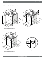
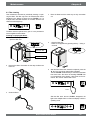
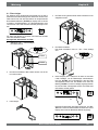
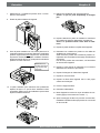
3ODDWVHQWRHVWHO
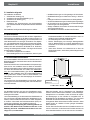
De Renovent Excellent kan middels de daartoe meegeleverde
ophangbeugels direct aan de wand worden bevestigd. Voor
een trillingsvrij resultaat dient een massieve wand met een minimale massa van 200 kg/m2 te worden gebruikt. Een gibo- of
metaalstut wand voldoet niet! Extra maatregelen zoals dubbele
beplating of extra stuts zijn dan noodzakelijk. Desgewenst is
ten behoeve van vloermontage een montagestoel leverbaar.
Verder dient rekening gehouden te worden met de volgende
punten:
+HWWRHVWHOPRHWZDWHUSDVZRUGHQJHSODDWVW
'H RSVWHOOLQJVUXLPWH PRHW ]RGDQLJ ZRUGHQ JHNR]HQ GDW
een goede condensafvoer met waterslot en verval voor
condenswater gemaakt kan worden.
'HRSVWHOOLQJVUXLPWHPRHWYRUVWYULM]LMQ
=RUJ LQ YHUEDQG PHW VFKRRQPDNHQ YDQ GH ¿OWHUV HQ RQderhoud voor een vrije ruimte van minimaal 70 cm aan
de voorzijde van het toestel en een vrije stahoogte van
1,8 m.
=RUJDOWLMGYRRUPLQLPDDOFPYULMHUXLPWHERYHQGHGLVplaykap, zodat deze altijd kan worden losgenomen.
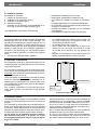
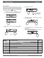
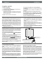
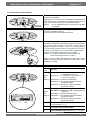
5.3 Aansluiten condensafvoer
De condensafvoer wordt bij de Renovent Excellent door het
onderpaneel geleid. Het condenswater moet via de binnenriolering worden afgevoerd.
De condensafvoer aansluiting wordt los bij het toestel meegeleverd en moet door de installateur onder in het toestel worden
geschroefd. Deze condensafvoeraansluiting heeft een uitwendige aansluitdiameter van 32 mm.
Hierop kan middels een lijmverbinding (eventueel een haakse
bocht) de condensafvoerleiding worden gemonteerd. De installateur kan de condensafvoer in de gewenste positie onder
in het toestel lijmen. De afvoer moet onder de waterspiegel in
de zwanenhals eindigen
Giet, voordat de condensafvoer op het toestel wordt aangesloten, water in de sifon of de zwanenhals om een waterslot
te krijgen.
Schroefverbinding
Lijmverbinding;
Ø32 mm
A
A = Minimale hoogte > 60 mm
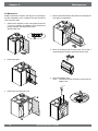
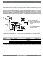
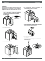
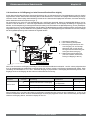
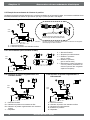
5.4 Aansluiten kanalen
Het luchtafvoerkanaal hoeft niet van een inregelklep te worden
voorzien; de luchthoeveelheden worden door het toestel zelf
geregeld.
Om condensatie op de buitenzijde van het buitenluchttoevoerkanaal en het luchtafvoerkanaal vanaf de Renovent Excellent
te voorkomen, dienen deze kanalen tot op het toestel uitwendig
dampdicht te worden geïsoleerd. Indien hiervoor Brink kunststof (EPE) buis wordt toegepast, is extra isolatie overbodig.
Om het geluid van de ventilatoren optimaal te dempen,
moet men tussen het toestel en de kanalen van en naar
de woning Brink akoestische slang toe te passen met een
lengte van 1,5 meter.
12
Hierbij dient rekening te worden gehouden met overspraak en
installatiegeluid, ook bij instortkanalen. Voorkom overspraak
door het kanaal met afzonderlijke aftakkingen naar de ventielen toe uit te voeren. Zo nodig dienen de toevoerkanalen te
worden geïsoleerd, bijvoorbeeld wanneer deze buiten de geisoleerde schil worden aangebracht.
Pas bij voorkeur Brink instortkanalen toe. Deze kanalen zijn
ontwikkeld met het oog op een lage kanaalweerstand.
Er moet voor de Renovent Excellent 400 een kanaaldiameter
van 180 mm worden toegepast; voor de Renovent Excellent 300
kan worden volstaan met kanaaldiameter van 150 of 160 mm.
Renovent Excellent 300/400
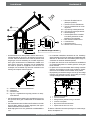
Installeren
Hoofdstuk 5
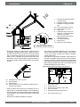
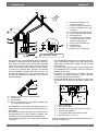
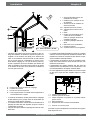
1 = Renovent Excellent links 2/2
(waterpas opstellen)
2 = Voorkeur toevoer ventilatielucht
3 = Toevoer ventilatielucht van onder
de pannen
4a = Vrije aanzuig onderzijde dakvlak
4b = Vrije aanzuig bovenzijde dakvlak
5 = Rioolontspanning
6 = Voorkeurplaats afvoer ventilatielucht; Brink geisoleerde ventilatiedakdoorvoer toepassen
7 = Brink kunststof HR WTW buis
8 = Condensafvoer
9 = Akoestische slang
10 = Kanalen van en naar woning
A
A = Minimale hoogte > 60 mm
'HEXLWHQOXFKWWRHYRHUGLHQWSODDWVWHYLQGHQYDQXLWGHEHschaduwde zijde van de woning, bij voorkeur uit de gevel of
overstek. Indien de buitenlucht van onder de pannen wordt
aangezogen, dient de aansluiting zo te worden uitgevoerd,
dat er geen condenswater in het dakbeschot ontstaat en er
geen water in kan lopen. Aanzuigen van de ventilatielucht
van onder de pannen is mogelijk als er via de boven- en
onderzijde van het dakvlak vrije lucht kan toetreden en de
riolering niet ontspant onder de pannen.
A
B
C
D
=
=
=
=
Afstand van 10 mm boven dakbeschot
Dakisolatie
Dichtschuimen
Pijp t.b.v. suppletielucht zorgvuldig isoleren en dampdicht afwerken
+HWDIYRHUNDQDDOGLHQW]RGDQLJGRRUKHWGDNEHVFKRWWHZRUden gevoerd, dat er geen condenswater in het dakbeschot
ontstaat.
+HWDIYRHUNDQDDOWXVVHQGH5HQRYHQW([FHOOHQWHQGHGDNdoorvoer dient zodanig te worden uitgevoerd, dat oppervlaktecondensatie wordt voorkomen.
0DDNDOWLMGJHEUXLNYDQHHQJHwVROHHUGHYHQWLODWLHGDNGRRUvoer.
'H PD[LPDDO WRHODDWEDUH ZHHUVWDQG YDQ KHW NDQDOHQV\steem bedraagt 150 Pa bij de maximale ventilatiecapaciteit.
Wanneer de weerstand van het kanalensysteem hoger is,
vermindert de maximale ventilatiecapaciteit.
'HSODDWVYDQGHDIYRHUYDQGHPHFKDQLVFKHYHQWLODWLHOXFKW
en rioolontluchting dient zo te worden gekozen, dat er geen
hinder ontstaat.
'HSODDWVYDQGHWRHYRHUYHQWLHOHQGLHQW]RGDQLJWHZRUGHQ
gekozen, dat vervuiling en tocht wordt voorkomen. Geadviseerd word om de Brink toevoerventielen toe te passen.
%LMWRHSDVVLQJYDQÀH[LEHOHVODQJHQPRHWHUELMGHPRQWDJH
rekening mee gehouden worden, dat de slang na verloop
van tijd vervangen dient te kunnen worden.
1
2
3
4
5
=
=
=
=
=
Brink toevoerventielen
Toevoer uit wand
Afzuigventiel in plafond of hoog in de wand
Voorkom overspraak
Bij voorkeur Brink instortkanalen
a = Spleet onder de deur van 2 cm.
Er dienen voldoende overstroomopeningen te worden aangebracht, deurspleet 2 cm.
Renovent Excellent 300/400
13
Hoofdstuk 5
Installeren
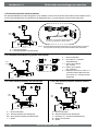
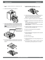
5.5 Elektrische aansluitingen
5.5.1 Aansluiten van de netstekker
Het toestel kan door middel van de aan het toestel gemonteerde stekker worden aangesloten op een goed bereikbare,
geaarde wandcontactdoos. De elektrische installatie moet voldoen aan de eisen van uw elektriciteitsbedrijf.
Waarschuwing
De ventilatoren en regelprint werken onder
hoogspanning. Bij werkzaamheden in het toestel dient het toestel spanningsvrij te worden
gemaakt door de netstekker los te nemen.
Houd rekening met de 1000 W. voorverwarmer
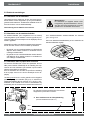
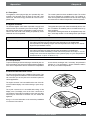
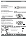
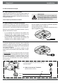
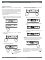
5.5.2 Aansluiten van de standenschakelaar
De standenschakelaar (niet meegeleverd met het toestel)
wordt aangesloten op de modulaire connector type RJ12 (connector X2) welke aan de achterzijde van de displaykap van het
toestel is geplaatst.
Voor aansluitvoorbeelden standenschakelaar zie schema’s
§11.2.1 t/m §11.2.4.
Ook is een draadloze afstandbediening of een combinatie van
standenschakelaars mogelijk.
Afhankelijk van welke type standenschakelaar wordt aangesloten kan men hier een RJ11 of RJ12 stekker op aansluiten.
%LM JHEUXLN YDQ HHQ VWDQGHQVFKDNHODDU PHW ¿OWHULQGLFDWLH
altijd een RJ12 stekker monteren in combinatie met een
6-aderige modulaire kabel
%LMJHEUXLNYDQHHQVWDQGHQVFKDNHODDU]RQGHU¿OWHULQGLcatie altijd een RJ11 stekker monteren in combinatie met
een 4-aderige modulaire kabel.
RJ12
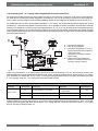
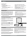
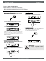
5.5.3 Aansluiten eBus cq OpenTherm connector
De Renovent Excellent kan zowel met Opentherm als met
eBus protocol werken. Afhankelijk van de instelling van stapnummer 08 in het instelmenu (zie hoofdstuk 13) kan worden
gekozen tussen eBus en OpenTherm.
Voor het aansluiten van een eBus of OpenTherm verbinding
zit de 2-polige connector X1 aan de achterzijde van de displaykap.
Het eBus protocol kan b.v. worden gebruikt voor het koppelen
(cascaderegeling) van toestellen (Zie §11.3). In verband met
polariteitgevoeligheid altijd de contacten X1-1 met X1-1 doorverbinden en de contacten X1-2 met X1-2 doorverbinden; bij
verwisseling van de contacten zal het toestel niet functioneren!
X1
De optioneel leverbare bedienmodule moet worden
aangesloten op deze eBus connector.
A Door installateur aan te sluiten bekabeling
(minimale draaddoorsnede 0,34 mm2)
A
nr.1
nr.2
14
Renovent Excellent 300/400
X1
Display weergave
Hoofdstuk 6
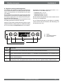
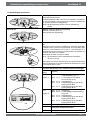
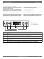
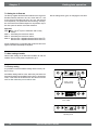
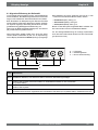
6.1 Algemene verklaring bedieningspaneel
Op het display kan uitgelezen worden wat de bedrijfssituatie
van het toestel is. Met een 4-tal bedieningstoetsen zijn instellingen in de programmatuur van de besturingsunit op te roepen
en te wijzigen.
Bij het inschakelen van de netspanning van de Renovent Excellent
zijn gedurende 2 seconden alle op het display aanwezige symbolen zichtbaar; tegelijk gaat ook de achtergrondverlichting (backlight) gedurende 60 seconden aan.
Wanneer een van de bedieningstoetsen wordt bediend dan zal
het display gedurende 30 seconden verlicht zijn.
Wanneer er geen toetsen worden bediend of wanneer er geen
afwijkende situatie is ontstaan (zoals b.v. blokkerende storing)
dan is op het display de bedrijfssituatie (zie § 6.2) zichtbaar.
1DEHGLHQLQJYDQGHµ0HQX¶WRHWVNDQPHQPHWGH³´RI³´
toets kiezen uit 3 verschillende menu’s nl.:
Instelmenu (SET); zie § 6.3
Uitleesmenu (READ), zie § 6.4
Servicemenu (SERV), zie § 6.5
Met de R-toets kan elk gekozen menu worden verlaten en komt
men terug in de bedrijfssituatie.
Om de achtergrondverlichting van het display in te schakelen
zonder dat in het menu iets verandert, druk kortstondig op de
R-toets (korter dan 5 sec.).
.
A = display
B = 4-tal bedieningstoetsen
C = service connector
A
B
C
Toets
Functie toets
Menu
Instelmenu activeren; naar volgende stap in het submenu; waardeverandering bevestigen
-
Scrollen; waarde aanpassen; Renovent Excellent in- cq. uitschakelen vanuit bedrijfssituatie (5 sec. ingedrukt houden)
+
Scrollen; waarde aanpassen
R
(pQVWDSWHUXJLQPHQXDDQJHSDVWHZDDUGHDQQXOHUHQ¿OWHUUHVHWVHFLQJHGUXNWKRXGHQIRXWKLVWRULHZLVVHQ
Renovent Excellent 300/400
15
Hoofdstuk 6
Display weergave
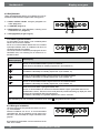
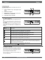
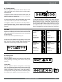
6.2 Bedrijfssituatie
Tijdens de bedrijfssituatie kunnen op het display een 4-tal verschillende situaties/waarden tegelijk worden weergegeven.
1 = Status ventilator situatie, weergave gekoppelde toestellen (zie § 6.2.1)
2 = Luchtdebiet (zie § 6.2.2)
3 = Meldingstekst ELMY WHNVW ¿OWHUVLWXDWLH DFWLYHULQJ H[WHUQ
schakelcontact etc. (zie § 6.2.3)
4 = Storingsymbool (zie § 8.1 en § 8.2)
6.2.1 Status systeemventilator
Op deze plaats van het display is een ventilatorsymbool
samen met een nummer zichtbaar.
Als de toe- en afvoerventilator draaien dan is het ventilator
symbooltje zichtbaar; staan de ventilatoren stil dan is het
ventilatorsymbooltje niet zichtbaar.
Het nummer achter het ventilatorsymbooltje geeft de ventilatorsituatie weer; voor verklaring van de nummers zie onderstaande tabel.
Status ventilatorsituatie op display
Omschrijving
De toe- en afvoerventilator draaien op 50 m3/h of staan stil. 1)
Deze situatie is afhankelijk van instelling stapnummer 1 (zie hoofdstuk 13)
1)
1
De toe- en afvoerventilator draaien volgens stand 1 van de standenschakelaar.
Luchtdebiet is afhankelijk van instelling stapnummer 2 (zie hoofdstuk 13).
2
De toe- en afvoerventilator draaien volgens stand 2 van de standenschakelaar.
Luchtdebiet is afhankelijk van instelling stapnummer 3 (zie hoofdstuk 13).
3
De toe- en afvoerventilator draaien volgens stand 3 van de standenschakelaar.
Luchtdebiet is afhankelijk van instelling stapnummer 4 (zie hoofdstuk 13).
Ƒ
Deze Renovent Excellent is gekoppeld middels eBus.
De toe- en afvoerventilator van de Renovent Excellent draaien volgens geschakelde stand van de
YHQWLODWLHVWDQG³PDVWHU´5HQRYHQWWHYHQVZRUGWDOOHHQELMFDVFDGHDDQVOXLWLQJRSGLVSOD\KHW³VODYH´
nummer van de betreffende Renovent aangegeven.
/XFKWGHELHWLVDIKDQNHOLMNYDQLQJHVWHOGHVWDSQXPPHUV³PDVWHU´5HQRYHQW
Bij toepassing van een 3-standenschakelaar zal de stand
niet gebruikt kunnen worden.
6.2.2 Weergave luchtdebiet
Hier wordt weergeven de ingestelde luchtdebiet van de toec.q. afvoerventilator.
Wanneer luchtdebiet van de toe- en de afvoerventilator
verschillend zijn, bijv. bij toepassing van een extern schakelcontact, dan wordt altijd de hoogste luchtdebiet weergegeven.
Bij softwarematig uitschakelen van het toestel komt hier de
WHNVW³2))´WHVWDDQ
16
Renovent Excellent 300/400
Display weergave
Hoofdstuk 6
6.2.3 Meldingstekst bij bedrijfssituatie
Op deze plaats van het display kan een meldingstekst koPHQWHVWDDQ'HPHOGLQJVWHNVW³)LOWHU´KHHIWDOWLMGYRRUUDQJ
t.o.v. de overige meldingsteksten.
De volgende meldingsteksten kunnen zichtbaar worden tijdens bedrijfssituatie:
Meldingstekst
op display
Omschrijving
FILTER
:DQQHHUGHWHNVW³),/7(5´RS
display verschijnt dan moet het
¿OWHUZRUGHQVFKRRQJHPDDNWUHVS
worden vervangen; voor uitgebreide informatie hierover zie § 9.1.
Slave 1, Slave
2 etc.
Bij gekoppelde toestellen wordt
bij de meldingstekst weergegeYHQZHONWRHVWHOGH³6ODYH´
WP³6ODYH´LVYRRUXLWJHEUHLGH
informatie hierover zie §11.3.
2S³0DVWHU´WRHVWHOZRUGWGH
normale weergave betreffende
ventilatiestand weergegeven.
Master - toestel
Slave - toestel
EWT
(Alleen bij Plusuitvoering)
CN1 of CN2
(Alleen bij Plusuitvoering)
V1 of V2
(Alleen bij Plusuitvoering)
:DQQHHUGHWHNVW³(:7´RS
display verschijnt is de aardwarmtewisselaar actief.
Voor uitgebreidere info, zie ook
§11.6.
:DQQHHUGHWHNVW³&1RI&1´
op display wordt weergegeven dan
is één van de externe schakelingangen actief, zie ook §11.7.
:DQQHHUGHWHNVW³9RI9´RS
display wordt weergegeven dan
is één van de 0 - 10 V. ingangen
actief, zie ook §11.8.
Renovent Excellent 300/400
17
Hoofdstuk 6
Display weergave
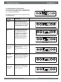
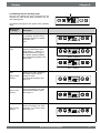
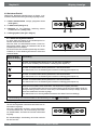
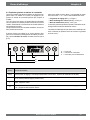
6.3 Instelmenu
Voor het optimaal functioneren van het toestel kunnen er in
het instelmenu instelwaarden worden gewijzigd waarmee het
toestel is aan te passen aan de opstellingssituatie; voor overzicht van deze instelwaarden zie hoofdstuk 13. Een aantal instelwaarden zoals de luchthoeveelheden zijn vastgelegd in de
ontwerpgegevens.
Waarschuwing:
Omdat veranderingen in het instelmenu de goede werking
van het toestel kunnen verstoren moet bij niet beschreven
instellingen overleg plaats vinden met Brink.
Onjuiste instellingen kunnen het goed functioneren van het
toestel ernstig verstoren!
4
Druk op ‘Menu´WRHWVYRRUVHOHFWLHJHNR]HQLQVWHOZDDUGH
1x
5
Wijzig m.b.v. ‘-‘ en ‘+’ toets geselecteerde instelwaarde.
6
Opslaan aangepaste instelwaarde
Het aanpassen van instelwaarden in het instelmenu:
1. Druk vanuit de bedrijfssituatie op de ‘MENU’- toets.
Aangepaste instelwaarde opslaan
1x
1x
2. Druk op de ‘MENU’- toets om het “instelmenu´WHDFWLYHren.
Niet opslaan aangepaste instelwaarde
Aangepaste waarde niet opslaan
instelmenu is actief
1x
2x
7
3
Kies m.b.v. de ‘+’ of de ‘- ‘ toets de aan te passen instelwaarde.
Voor wijzigen andere instelwaarden, herhaal stap 3 t/m 6.
Wanneer men geen instelwaarden meer wilt aanpassen
en terug wilt gaan naar bedrijfssituatie, druk dan op ‘R’toets.
Instelwaarde
Stapnummer
instelwaarde
Terug naar bedrijfssituatie
Selectie aan te passen instelwaarde.
18
Renovent Excellent 300/400
Display weergave
Hoofdstuk 6
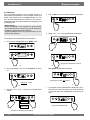
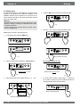
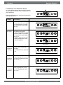
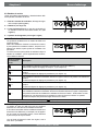
6.4 Uitleesmenu
Met het uitleesmenu kunnen een aantal actuele waarden van
sensoren worden opgeroepen om meer informatie te krijgen
over de werking van het toestel. Het wijzigen van waarden of
instellingen is niet mogelijk in het uitleesmenu. Het uitleesmenu krijgt men te zien door de volgende handelingen te verrichten:
3. Activeer het uitleesmenu.
uitleeswaarde
1. Druk vanuit de bedrijfssituatie op de ‘MENU’- toets. Op het
display is nu het instelmenu zichtbaar.
Stapnr. uitleeswaarde;
voor verklaring zie onderstaande tabel
4
Met behulp van de ‘+’ en de ‘-’ toets kan er door het uitleesmenu ‘bladeren’.
5
Druk 2x op ‘R’ - toets om terug te gaan naar bedrijfssituatie.
Indien 5 minuten geen toets wordt bediend, dan keert het
toestel automatisch terug naar de bedrijfssituatie.
bedrijfssituatie
instelmenu
2. Ga m.b.v. de ‘+’ en de ‘-’ toets naar het uitleesmenu.
bedrijfssituatie
uitleesmenu
2x
Stapnr. uitleeswaarde
Omschrijving uitleeswaarde
Eenheid
01
Actuele temperatuur uit de woning
°C
02
Actuele temperatuur van buitensensor
°C
03
Bypass status (ON = bypassklep open, OFF = bypassklep dicht)
04
Status vorstregeling (ON = vorstregeling actief, OFF = vorstregeling niet actief)
05
Actuele kanaaldruk toevoer
Pa
06
Actuele kanaaldruk afvoer
Pa
07
Actuele luchthoeveelheid toevoerventilator
m3/h
08
Actuele luchthoeveelheid afvoerventilator
m3/h
09
Actuele relatieve vochtigheid (RH-sensor is als optie leverbaar)
%
Renovent Excellent 300/400
19
Hoofdstuk 6
Display Weergave
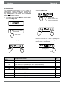
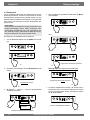
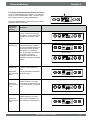
6.5 Servicemenu
In het servicemenu worden de laatste 10 foutmelding getoond.
4
Met behulp van de ‘+’ en de ‘-’ toets kan men door de meldingen in het servicemenu ‘bladeren’.
Bij een vergrendelende storing zijn het instelmenu en uitleesmenu geblokkeerd en kan alleen het servicemenu worden
geopend; bij bediening van de ‘menu’-toets wordt het servicemenu rechtstreeks geopend.
Het servicemenu krijgt men te zien door de volgende handelingen te verrichten:
1. Druk vanuit de bedrijfssituatie op de ‘MENU’- toets. Op het
display is nu het instelmenu te zien.
- Weergave geen enkele foutmelding.
bedrijfssituatie
- Actuele foutmelding (steeksleutel op display).
instelmenu
2. Ga met behulp van de ‘+’ en de ‘-’ toets naar het servicemenu.
- Opgeloste foutmelding (geen steeksleutel op
display).
5
servicemenu
Druk 2x op ‘R’ - toets om terug te gaan naar bedrijfssituatie.
Indien 5 minuten geen toets wordt bedient, dan keert het
toestel automatisch terug naar de bedrijfssituatie.
3. Activeer het servicemenu.
bedrijfssituatie
2x
Foutcode; voor
verklaring foutcode
zie § 8.1 en § 8.2
Nr. foutmelding
20
Alle foutmeldingen kunnen worden gewist door in servicemenu
VHFRQGHQRSGH³5´WRHWVWHGUXNNHQGLWLVDOOHHQPRJHOLMN
wanneer er geen actieve storing is!
Renovent Excellent 300/400
In werking stellen
Hoofdstuk 7
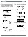
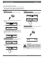
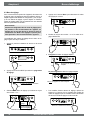
7.1 In- en uitschakelen toestel
Het toestel kan op twee manieren worden in- of uitgeschakeld:
- In- en uitschakelen door aansluiten of losnemen netstekker
- Softwarematig in- en uitschakelen m.b.v. display op het toestel
Inschakelen:
Netvoeding inschakelen:
Sluit de 230V. netstekker aan op de elektrische installatie.
Uitschakelen:
Softwarematig uitschakelen:
Druk 5 sec. op de “-´WRHWVRPKHWWRHVWHOVRIWZDUHPDWLJXLW
te schakelen. Er verschijnt de tekst ‘OFF’ op het display.
Gedurende 2 sec. worden alle symbolen van het display getoond.
>5 sec.
2 sec.
Gedurende 2 sec. wordt de software versie getoond.
2 sec.
Netvoeding uitschakelen;
Neem de 230V. netstekker los van de elektrische installatie,
het toestel is nu spanningsvrij.
Op display is nu geen enkele weergave te zien.
De Renovent Excellent functioneert hierna meteen volgens
de ingestelde stand van de standenschakelaar. Is er geen
standenschakelaar aangesloten dan draait het toestel altijd
op stand 1.
Softwarematig Inschakelen:
Wanneer de Renovent Excellent softwarematig is uitgezet,
VWDDWRSKHWGLVSOD\GHWHNVW³2))´
Het toestel wordt ingeschakeld door 5 sec. op de toets ‘-’ te
drukken.
Waarschuwing
Maak bij werkzaamheden in het toestel altijd
eerst het toestel spanningsvrij door het toestel
softwarematig uit te zetten en hierna de netstekker los te nemen.
> 5 sec.
Renovent Excellent 300/400
21
Hoofdstuk 7
In werking stellen
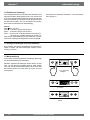
7.2 Instellen luchthoeveelheid
De luchthoeveelheden van de Renovent Excellent zijn af fabriek voor de Renovent Excellent 300 ingesteld op respectievelijk 50, 100, 150 en 225 m3/h en voor de Renovent Excellent
400 ingesteld op respectievelijk 50, 100, 200 en 300 m3/h. De
prestaties en het energieverbruik van de Renovent Excellent
zijn afhankelijk van de drukverlies in het kanalensysteem, alsPHGHGHZHHUVWDQGYDQGH¿OWHUV
Voor het wijzigen van de luchthoeveelheden in het instelmenu,
zie §6.3.
Belangrijk:
Stand : is 0 of 50 m3/h (niet bij 3-standenschakelaar).
Stand 1 : moet altijd lager zijn dan stand 2.
Stand 2 : moet altijd lager zijn dan stand 3;
Stand 3 : Renovent 300 - instelbaar tussen 50 en 300 m3/h
Renovent 400 - instelbaar tussen 50 en 400 m3/h;
Indien niet aan deze voorwaarden word voldaan wordt automatisch de luchthoeveelheid van de bovenliggende stand aangepast.
7.3 Overige instellingen installateur
Het is mogelijk nog meer instellingen van de Renovent Excellent te veranderen. Hoe deze kunnen worden gewijzigd staat
vermeld in §6.3.
7.4 Fabrieksinstelling
Het is mogelijk om alle gewijzigde instellingen tegelijk terug te
zetten naar de fabrieksinstelling.
Alle gewijzigde instellingen staan weer op de waarde zoals het
Renovent Excellent toestel af fabriek wordt geleverd; ook alle
meldcodes/ foutcodes zijn uit het service menu gewist.
'H¿OWHUPHOGLQJZRUGWKLHUELMQLHWJHUHVHW
> 10 sec. gelijktijdig
indrukken
3 sec. zichtbaar
bedrijfssituatie
22
Renovent Excellent 300/400
Storing
Hoofdstuk 8
8.1 Storingsanalyse
Wanneer de regeling in het toestel een storing detecteert, wordt
dit op het display weergegeven door middel van een sleutelsymbooltje eventueel samen met een storingsnummer.
Het toestel maakt onderscheidt tussen een storing waarbij het
toestel nog (beperkt) blijft functioneren en een ernstige (vergrendelende) storing waarbij beide ventilatoren worden uitgeschakeld.
Bij een vergrendelende storing is ook het instel en uitleesmenu
uitgeschakeld en is alleen het servicemenu te bekijken.
Het toestel blijft in deze storing staan totdat het betreffende
probleem is opgelost; hierna zal het toestel zichzelf resetten
(Auto reset) en keert het display terug naar de weergave van
de bedrijfssituatie.
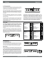
Storing E999
Indien er bij het spanning op het toestel zetten gelijk de melding E999 op het display verschijnt dan is de gemonteerde regelprint niet geschikt voor dit toestel of de positie van de dipswitches op de regelprint staan verkeerd.
Voor lokatie dipswitches op print zie § 10.1
Controleer in dit geval of de dipswitches op de regelprint staan
ingesteld volgens afbeelding instelling dipswitches; is dit wel
het geval en wordt nog steeds de melding E999 weergegeven
vervang dan de regelprint door een print van het juiste type.
De ventilatoren worden aangestuurd op basis van de waarden
van op de regelprint gemonteerde druksensoren. Per ventilator
lopen 2 drukslangen naar de regelprint toe. Wanneer de slangen niet goed worden aangesloten, lek of verstopt zijn zal dus
een verkeerde druk worden waargenomen en de ventilatoren
worden dan ook niet meer op de juiste manier aangestuurd.
Controleer bij twijfel over de juiste werking van het toestel de
aansluitingen van de drukslangen.
Renovent
Excellent 300
type 4/0
Renovent
Excellent 300 Plus
type 4/0
Renovent
Excellent 300
type 2/2 & 3/1
Renovent
Excellent 300 Plus
type 2/2 & 3/1
Renovent
Excellent 400
type 4/0
Renovent
Excellent 400 Plus
type 4/0
Renovent
Excellent 400
type 2/2 & 3/1
Renovent
Excellent 400 Plus
type 2/2 & 3/1
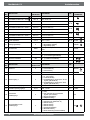
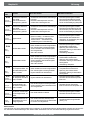
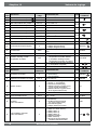
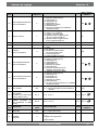
8.2 Displaycodes
Niet vergrendelende storing
Wanneer het toestel een niet vergrendelende storing signaleert
dan zal het toestel nog wel (beperkt) blijven functioneren. Op
het display wordt wel het storingssymbool (sleutel) weergegeven.
Vergrendelende storing
Wanneer het toestel een vergrendelende storing signaleert
dan zal het toestel niet meer functioneren. Op het (permanent
verlicht) display wordt het storingssymbool (sleutel) tezamen
met een storingscode worden weergegeven. Op de standenschakelaar (indien van toepassing) zal het rode ledje knipperen. Neem contact op met de installateur voor herstel van deze
storing. Een vergrendelende storing is niet op te heffen door
het spanningsloos maken van het toestel; eerst dient de storing
te worden verholpen.
Renovent Excellent 300/400
23
Hoofdstuk 8
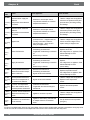
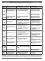
Foutcode
Oorzaak
Storing
Actie toestel
Actie installateur
E100
- Schakelt over naar constant toerental
regeling.
- Bij buitentemperatuur beneden 0°C gaat
voorverwarmer aan.
Maak toestel spanningsloos.
Controleer rode drukslangen
(incl. drukbuisjes) op vervuiling,
knikken en beschadiging.
E101
- Schakelt over naar constant toerental
regeling.
- Bij buitentemperatuur beneden 0°C gaat
voorverwarmer aan.
Maak toestel spanningsloos.
Controleer blauwe drukslangen
(incl. drukbuisjes) op vervuiling,
knikken en beschadiging.
E103
- Geen.
Maak toestel spanningsloos.
6WURRPWHODDJĺVWDSSHQPRWRUQLHWJRHG
Controleer aansluiting stappenaangesloten of defect;
motor; vervang bedrading resp.
6WURRPWHKRRJĺNRUWVOXLWLQJLQEHGUDGLQJ
stappenmotor.
of stappenmotor).
Druksensor toevoerventilator
defect.
Rode drukslangen verstopt of
(niet vergrendelende storing) ³JHNQLNW´
Druksensor afvoerventilator
defect.
(niet vergrenBlauwe drukslangen verstopt
delende storing)
RI³JHNQLNW´
Bypass defect.
(niet vergrendelende storing)
Afvoerventilator defect.
- Beide ventilatoren worden uitgeschakeld.
- Voorverwarmer(s) wordt uitgeschakeld.
- Indien van toepassing: Naverwarmer(s)
wordt uitgeschakeld.
- Elke 5 minuten herstart.
Maak toestel spanningsloos.
Vervang afvoerventilator.
Zet weer spanning op toestel;
storing is automatisch gereset.
Controleer bekabeling.
Toevoerventilator defect.
- Beide ventilatoren worden uitgeschakeld.
- Voorverwarmer(s) wordt uitgeschakeld.
- Indien van toepassing: Naverwarmer(s)
wordt uitgeschakeld.
- Elke 5 minuten herstart.
Maak toestel spanningsloos.
Vervang toevoerventilator.
Zet weer spanning op toestel;
storing is automatisch gereset.
Controleer bekabeling.
- Beide ventilatoren worden uitgeschakeld.
- Voorverwarmer(s) wordt uitgeschakeld.
- Bypass sluit en wordt geblokkeerd.
Maak toestel spanningsloos.
Vervang temperatuurvoeler.
Zet weer spanning op toestel;
storing is automatisch gereset.
E104
(vergrendelende
storing)
E105
(vergrendelende
storing)
E106
De temperatuurvoeler die de
(vergrendelende buitenluchttemperatuur meet
storing)
is defect.
E107
De temperatuurvoeler die de
temperatuur van de afzuiglucht - Bypass sluit en wordt geblokkeerd.
(niet vergrendelende storing) meet is defect.
E108
Indien aanwezig: De tempera-
(niet vergrentuurvoeler die de externe temdelende storing)
peratuur meet is defect.
- Naverwarmer wordt uitgeschakeld.
- Indien van toepassing: Aardwarmtewisselaar wordt uitgeschakeld.
Vervang externe temperatuurvoeler.
- Toestel blijft functioneren
Maak toestel spanningsloos.
Vervang RH-sensor
- Toestel doet niets; ook rode storingsledje
op standenschakelaar wordt niet aangestuurd.
Zet dipswitches op juiste positie
(zie § 8.1).
E111
RH-sensor defect
(niet vergrendelende storing)
E999
Dipswitches op besturingprint
(vergrendelende niet juist ingesteld.
storing)
Maak toestel spanningsloos.
Vervang binnentemperatuurvoeler.
Let op!
Indien stand 2 bij een standenschakelaar niet werkt dan is de modulaire connector standenschakelaar verkeerd om aangesloten.
Eén van de RJ-connectoren naar de standenschakelaar afknippen en een nieuwe connector omgekeerd monteren.
24
Renovent Excellent 300/400
Onderhoud
Hoofdstuk 9
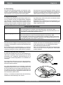
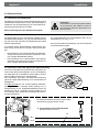
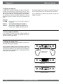
9.1 Filter reinigen
Het onderhoud voor de gebruiker is beperkt tot het periodiek
UHLQLJHQ RI YHUYDQJHQ YDQ GH ¿OWHUV +HW ¿OWHU KRHIW SDV WH
worden gereinigd indien dit wordt aangegeven op het display
(hierop verschijnt tekst “FILTER´RILQGLHQHHQVWDQGHQVFKDNHODDU PHW ¿OWHULQGLFDWLH LV JHSODDWVW KHW URGH OHGMH ELM GH]H
schakelaar brandt.
3ODDWVGH¿OWHUVWHUXJRSGH]HOIGHZLM]H]RDOV]HHUXLW]LMQ
gehaald.
,HGHU MDDU GLHQHQ GH ¿OWHUV YHUYDQJHQ WH ZRUGHQ +HW WRHVWHO
PDJQRRLW]RQGHU¿OWHUVZRUGHQJHEUXLNW
6FKRRQPDNHQFTYHUYDQJHQYDQGH¿OWHUV
1
- Druk 5 sec. op de ‘-’ toets.
2SHQGH¿OWHUGHXU
6OXLWGH¿OWHUGHXU
- Schakel toestel in door 5 sec. op de “-´WRHWVWHGUXNNHQ
> 5 sec.
100
> 5 sec.
$IYRHUOXFKW¿OWHU
7RHYRHUOXFKW¿OWHU
9HUZLMGHU GH ¿OWHUV 2QWKRXGW RS ZHONH PDQLHU GH ¿OWHUV
eruit worden gehaald.
1D KHW VFKRRQ PDNHQ FT YHUYDQJHQ YDQ GH ¿OWHUV GH
“R´WRHWVVHFLQGUXNNHQRPGH¿OWHULQGLFDWLHWHUHVHWWHQ
De tekst “FILTER´ ]DO NRUWVWRQGLJ NQLSSHUHQ WHU EHYHVWLJLQJGDWGH¿OWHUV]LMQJHUHVHW2RNZDQQHHUGHPHOGLQJ
“FILTER´QRJQLHWZRUGWZHHUJHJHYHQRSGLVSOD\NDQHHQ
¿OWHUUHVHWZRUGHQJHJHYHQGH³WHOOHU´]DOGDQZHHURSQXO
worden gezet.
5 sec.
5HLQLJGH¿OWHUV
1DGH¿OWHUUHVHWYHUGZLMQWGHWHNVW³FILTER´KHWODPSMH
bij de standen schakelaar is weer uit en het display staat
weer in de bedrijfssituatie.
Renovent Excellent 300/400
25
Hoofdstuk 9
Onderhoud
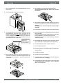
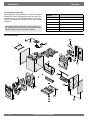
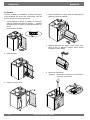
9.2 Onderhoud
Het onderhoud voor de installateur bestaat uit het reinigen van
de wisselaar en de ventilatoren. Afhankelijk van de omstandigheden dient dit circa eens per 3 jaar plaats te vinden.
1
4
Verwijder de warmtewisselaar. Voorkom beschadiging van
de schuimdelen in het toestel.
5
Reinig de warmtewisselaar met warm water (max. 55 ºC)
en gangbaar afwasmiddel. Spoel de wisselaar na met
warm water.
6
Neem displaykap los.
Let op! Eerst connectoren aan achterzijde displaykap
losnemen.
Schakel het toestel uit middels het bedieningspaneel (Druk
gedurende 5 seconden op de ‘-’ toets; het toestel wordt
softwarematig uitgezet) en schakel de netvoeding uit.
2SHQGH¿OWHUGHXU
> 5 sec.
9HUZLMGHUGH¿OWHUV
2x
Verwijder het voordeksel.
4
Y
J
3
J
X
26
Renovent Excellent 300/400
Onderhoud
Hoofdstuk 9
7
Neem 4 drukslangen en 3 connectoren los van print.
8
Schuif het ventilatordeel uit het toestel.
11 Reinig de ventilatoren middels een zachte borstel.
Zorg dat de balanceergewichten niet verschuiven!
12 Plaats losgenomen deel van ventilatordeel weer terug en
sluit de losgenomen drukslangen weer aan op de drukbuisjes.
Let op dat er geen vuil in de drukbuisjes komt!
13 Plaats het complete ventilatordeel terug in het toestel.
9
Leg het ventilatordeel op een vlakke ondergrond met de
drukslange naar boven. Verwijder de rode- en blauwe
drukslang zonder zwarte markering van de in het ventilatordeel gemonteerde drukbuisjes. Draai nu het schuimdeel
om zodat het deel met de drukslangen naar beneden toe
ligt.
Hier rode- en blauwe
drukslang zonder
markering losnemen!
14 Sluit drukslangen en ventilatorkabels weer aan op print.
Let voor de juiste positie drukslangen op de markeringssticker op de druksensoren.
Voor juiste positie connectoren zie sticker in toestel.
15 Monteer het displaykap en plaats de losgenomen connectoren aan de achterzijde van de displaykap weer terug.
16 Plaats de warmtewisselaar terug in het toestel.
17 Plaats het voordeksel.
3ODDWV GH ¿OWHUV WHUXJ LQ KHW WRHVWHO PHW GH VFKRQH ]LMGH
richting de wisselaar.
6OXLWGH¿OWHUGHXU
20 Schakel de stroomtoevoer in.
21 Schakel het toestel in middels het bedieningspaneel (druk
5 seconden op de toets “-´
10 Het ventilatordeel kan nu voorzichtig worden gedeeld zodat beide ventilatoren bereikbaar zijn; let op dat de ventilatoren in het onderste ventilatordeel blijven liggen!
1DUHLQLJHQYDQKHW¿OWHURISODDWVLQJYDQHHQQLHXZ¿OWHU
GH¿OWHULQGLFDWLHUHVHWWHQGRRUVHFRQGHQRSGH³R´WRHWV
te drukken
Renovent Excellent 300/400
27
Hoofdstuk 10
Elektrische schema
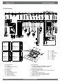
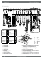
10.1 Aansluitschema
L
X4
12345678
N
Z
C6
C7
12345678
C
H
K
O
U
T S R Q
M
F
3
E
G
A
Renovent
Excellent 300
type 4/0
Renovent
Excellent 300 Plus
type 4/0
Renovent
Excellent 300
type 2/2 & 3/1
Renovent
Excellent 300 Plus
type 2/2 & 3/1
X1
D
Renovent
Excellent 400
type 4/0
Renovent
Excellent 400 Plus
type 4/0
Renovent
Excellent 400
type 2/2 & 3/1
Renovent
Excellent 400 Plus
type 2/2 & 3/1
A=
B=
C=
D=
E=
F=
G=
H=
J=
K=
L=
Standenschakelaar
Voorverwarmer
Buitentemperatuurvoeler
Regelprint
Toevoerventilator
Afvoerventilator
Bedieningspaneel
Binnentemperatuurvoeler
Serviceaansluiting
Klepmotor bypass
Renovent Plus uitvoering
28
P
B
X4
X6
C1
C2
C3
C5
C6
C7
C10
C11
=
=
=
=
=
=
=
=
bruin
blauw
groen/geel
wit
draad nr.1
draad nr.2
geel
groen
N = Niet van toepassing
O = E-busconnector (polariteitgevoelig) of Open Therm,
toepassing afhankelijk van stapnummer 8
P = Naverwarmer (Plus uitvoering)
Q = Uitgang 0+10V(Plus uitvoering)
R = Sensor naverwarmer of buitensensor aardwarmtewisselaar
(Plus uitvoering)
S = 24 volt aansluiting(Plus uitvoering)
T = Ingang 0-10V (of maakcontact) (Plus uitvoering)
U = Maakcontact (of ingang 0-10V) (Plus uitvoering)
Z = RH-sensor (optie)
Renovent Excellent 300/400
J
Elektrische aansluitingen accessoires
Hoofdstuk 11
11.1 Aansluitingen connectoren
Connector X1
Niet geschikt
voor 230V!
EBus resp. OpenTherm connector X1
Twee-polige schoefconnector
Af fabriek ingesteld als eBus connector; door aanpassing van stapnummer 8 in het instelmenu ook als OpenTherm connector toepasbaar (zie
§11.3). Alleen geschikt voor laagspanning.
Let op: Bij eBus toepassing is deze connector polariteits gebonden.
Connector X2
Modulaire connector X2 tbv toerenregeling
Modulaire connector type RJ-12
Alleen geschikt voor laagspanning.
&RQQHFWRU;DOOHHQELM3OXVXLWYRHULQJ
Connector X14 t.b.v. aansluiten naverwarmer of extra voorverwarmer
Twee-polige schroef connector (bereikbaar na losnemen displaykap).
Af fabriek is deze connector niet geactiveerd; door aanpassing stapQXPPHULQKHWLQVWHOPHQXYDQ³´QDDU³´YRRUYHUZDUPHURI³´
(naverwarmer) kan deze connector worden gebruikt voor aansluiten naverwarmer resp extra voorverwarmer.
Maximaal aan te sluiten vermogen is 1000W.
Let op: Bij naverwarmer ook de temperatuursensor aansluiten
op X15-7 en X15-8.
Maak gebruik van de bij de Plus uitvoering extra gemonteerde trekontlaster in de displaykap om de 230V. kabel naar de naverwarmer cq extra
voorverwarmer door te voeren.
&RQQHFWRU;DOOHHQELM3OXVXLWYRHULQJ
&RQQHFWRU;SROLJHWEYDDQVOXLWHQVSHFLDOHXLWYRHULQJHQ
AanToepassing
sluiting
1&2
Stapnr. 15 = 0: maakcontact
(= fabrieksinstelling) (§11.7)
(ingang 1) Stapnr. 15 = 1: 0 - 10V ingang; X15-1=GND &
15-2=0-10V (zie §11.8)
Stapnr. 15 = 2: verbreekcontact
Stapnr. 15 = 3: schakeluitgang/ bypas open ¼12V;
bypass gesloten ¼0V
Stapnr. 15 = 4: schakeluitgang/ bypas open ¼0V;
bypass gesloten ¼12V
3&4
(ingang 2)
12345 6789
X-15
Stapnr. 21 = 0: maakcontact
Stapnr. 21 = 1: 0 - 10V ingang (= fabrieksinstelling)
(zie §11.8).
Stapnr. 21 = 2: verbreekcontact
Stapnr. 21 = 3: schakeluitgang/ bypas open ¼12V;
bypass gesloten ¼0V
Stapnr. 21 = 4: schakeluitgang/ bypas open ¼0V;
bypass gesloten ¼12V
5&6
Aansluiting 24 volt , max. 4,5 VA(5 = ground , 6 = +)
7&8
Aansluiting sensor naverwarmer of
buitensensor aardwarmtewisselaar
9
Stuursignaal klep 0 of 10 V ( 9 = + , 5 = ground)
Renovent Excellent 300/400
29
Hoofdstuk 11
Elektrische aansluitingen accessoires
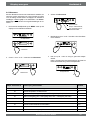
11.2 Aansluitvoorbeelden standenschakelaar
Een standenschakelaar kan worden aangesloten op de modulaire connector X2 van de Renovent Excellent. Deze modulaire connector X2 is direct bereikbaar aan de achterzijde van de displaykap (zie §11.1) zonder dat deze hoeft te worden losgenomen.
6WDQGHQVFKDNHODDUPHW¿OWHULQGLFDWLH
230V
50Hz
Draadkleur C1 t/m C6 kan variëren afhankelijk
van het type toegepaste modulaire kabel.
Let op:
Bij de toegepaste modulaire kabel moeten van beide modulaire connectoren
KHW³OLSMH´QDDUGHPDUNHULQJRSGHPRGXODLUHNDEHOZRUGHQJHPRQWHHUG
A = Renovent Excellent
% 6WDQGHQVFKDNHODDUPHW¿OWHULQGLFDWLH
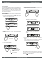
'UDDGOR]HDIVWDQGEHGLHQLQJ]RQGHU¿OWHULQGLFDWLH
A = Renovent Excellent
B = Ontvanger t.b.v. draadloze
afstandbediening
C = Zender met 4 standen
(bijv. keuken)
D = Zender met 2 standen
(bijv. badkamer)
E = Eventueel extra aan te sluiten 2 of
4 standen zenders (Maximaal 6 zenders kunnen op 1 ontvanger worden
aangemeld)
230V
50Hz
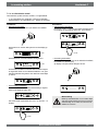
([WUDVWDQGHQVFKDNHODDUPHW¿OWHULQGLFDWLH
230V
50Hz
230V
50Hz
A = Renovent Excellent
% 6WDQGHQVFKDNHODDUPHW¿OWHULQGLFDWLH
% ([WUDVWDQGHQVFKDNHODDUPHW¿OWHULQGLFDWLH
C = Splitter
30
11.2.4 Extra standenschakelaar draadloze afstandbediening
A = Renovent Excellent
% 6WDQGHQVFKDNHODDUPHW¿OWHULQGLFDWLH
C = Ontvanger t.b.v. draadloze afstandbediening
D = Zender met 2 standen
E = Splitter
Renovent Excellent 300/400
Elektrische aansluitingen accessoires
Hoofdstuk 11
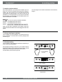
11.3 Koppelen meerdere Renovent Excellent toestellen middels eBus contact; alle toestellen gelijke luchtdebiet
Belangrijk:
I.v.m. polariteitsgevoeligheid altijd de eBus contacten X1-1 met elkaar doorverbinden en de contacten X1-2 met
elkaar doorverbinden. Nooit X1-1 en X1-2 met elkaar doorverbinden!
Maximaal 10 toestellen
(1 Master + max. 9 Slave)
230V
50Hz
230V
50Hz
9RRU00DVWHU
Stapnummer 9 instellen op 0
(= fabrieksinstelling).
Op display weergave ventilatiestand
1, 2 of 3.
A
B
M
C1 t/m C*
230V
50Hz
9RRU&6ODYH
Stapnummer 9 instellen op 1
(= Slave 1).
Op display weergave altijd
YHQWLODWLHVWDQGƑ
= Standenschakelaar
= 2-Polige connector
= Renovent Excellent (Master)
= Renovent Excellent (Slave); maximaal
10 toestellen koppelen via Ebus
Alle Renovents hebben zelfde luchtdebieten als de
Renovent welke ingesteld is als “Master”.
9RRU&6ODYH
Stapnummer 9 instellen op 2
(= Slave 2).
Op display weergave altijd
YHQWLODWLHVWDQGƑ
Stap
Omschrijving
nr.
8
Type
communicatie
9
eBus adres
FabrieksBereik
instelling
eBus
0
0t ( = Opentherm)
eBus
0 = master
1 t/m 9 = slave 1 t/m 9
$DQVOXLWHQ5+YRFKWLJKHLGVVHQVRU
230V
50Hz
A
B
C
D
E
=
=
=
=
=
Renovent Excellent
Regelprint
RH (vochtigheids) - sensor
Bij RH-sensor meegeleverde kabel
Kanaal uit woning
C1
C2
C3
= bruin
= blauw
= groen/geel
FabrieksStap
Bereik
Omschrijving
instelling
nr.
Inschakelen
OFF = uitgeschakeld
30
OFF
RH-sensor
ON = ingeschakeld
+2 meest gevoelig
+1 Ĺ
31 Gevoeligheid
0
0 basis instelling RH-sensor
-1 Ļ
-2 minst gevoelig
Renovent Excellent 300/400
31
Hoofdstuk 11
Elektrische aansluitingen accessoires
11.5 Bedradingsschema aansluiting naverwarmer of extra voorverwarmer
DOOHHQPRJHOLMNELM5HQRYHQW([FHOOHQW3OXV
De naverwarmer of extra voorverwarmer worden elektrisch op gelijke wijze aangesloten; alleen is bij een naverwarmer ook nog een
temperatuurvoeler aanwezig welke op connector X15 moet worden aangesloten. Voor uitgebreidere informatie betreffende de montage van de naverwarmer of extra voorverwarmer, zie de bij de verwarmer meegeleverde montageinstructie.
Extra Voorverwarmer
Naverwarmer
D
230V
50Hz
230V
50Hz
C1
C2
C3
C4
×
A
B
C
D
E
F
G
Renovent Excellent
Plus
Plus print
Verwarmingsspiraal
max. 1000 W
Maximaalbeveiliging
met handreset
Led maximaal beveiliging; verlicht wanneer
ingeschakeld
Door installateur aan
te sluiten kabel
Stromingsrichting
lucht door verwarmer
I=
Naar woning
II =
Naar buiten
III =
Uit woning
IV =
Van buiten
Verwarmer
32
0
0 = uit
1 = voorverwarmer
2 = naverwarmer
)
Stromingsrichting lucht
door verwarmer
Stapnr. Omschrijving
I=
Naar woning
II =
Naar buiten
III =
Uit woning
IV =
Van buiten
Fabrieksinstelling Bereik
13
Verwarmer
0
14
Temp. naverwarmer
21°C
Renovent Excellent 300/400
bruin
blauw
groen/geel
zwart
wit
×
A Renovent Excellent Plus
B Plus print
Verwarmingsspiraal max.
C
1000 W
D Temperatuurvoeler
Maximaalbeveiliging met
E
handreset
Led maximaal beveiliging;
F verlicht wanneer ingeschakeld
Door installateur aan te
G
sluiten kabels
H
Stap nr. Omschrijving Fabrieksinstelling Bereik
13
C1
C2
C3
C4
C5
bruin
blauw
groen/geel
zwart
0 = uit
1 = voorverwarmer
2 = naverwarmer
)
15°C - 30°C
Elektrische aansluitingen accessoires
Hoofdstuk 11
$DQVOXLWYRRUEHHOGDDUGZDUPWHZLVVHODDUDOOHHQPRJHOLMNELM5HQRYHQW([FHOOHQW3OXV
䊠
30°C
Bypass
䊢
䊡
䊣
䊣
25°C
B
Op de Renovent Excellent Plus kan een aardwarmtewisselaar worden aangesloten.
De aardwarmtewisselaar kan worden aangesloten
op aansluiting nr.5 (GND) en nr.9 (+) van de 9-polige connector X15; deze 9-polige connector is direct
aan de achterzijde van de bovenkant bereikbaar
zonder dat demontage van de displaykap nodig is.
Sluit de buitentemperatuurvoeler aan op nr. 7 en
nr.8 van de 9-polige connector.
Bij aansluiten aardwarmtewisselaar is het niet meer
mogelijk om een naverwarmer op de Renovent aan
te sluiten!
䊠
Bypass
䊢
A = Minimale temperatuur
B = Maximale temperatuur
䊡
I = Naar woning
15°C
䊣
䊣
II = Naar buiten
䊠
III = Uit woning
Bypass
䊢
IV = Van buiten
䊡
10°C
䊣
䊣
3°C
A
䊠
0°C
FabrieksBereik
instelling
ON =
Ingeschakeld
Inschakelen aardOFF
27
OFF =
warmtewisselaar
Uitgeschakeld
Minimale tempe28 ratuur aardwarm5°C 0 - 10°C
tewisselaar
Maximale tempe29 ratuur aardwarm25°C 15 - 40°C
tewisselaar
Stap
Omschrijving
nr.
Bypass
䊢
Bij toepassing van een aardwarmtewisselaar moet
GH VWDSQXPPHU ZRUGHQ JHZLM]LJG YDQ ³2))´
QDDU ³21´ :DQQHHU GH OXFKW GRRU GH DDUGZDUPtewisselaar wordt geleidt, wordt op het display van
GH5HQRYHQW([FHOOHQW3OXVGHWHNVW³(:7´ZHHUgegeven.
䊡
䊣
䊣
Renovent Excellent 300/400
33
Hoofdstuk 11
Elektrische aansluitingen accessoires
$DQVOXLWHQH[WHUQVFKDNHOFRQWDFWDOOHHQPRJHOLMNELM5HQRYHQW([FHOOHQW3OXV
Op de Renovent Excellent Plus kan een extern schakelcontact (bijv. schakelaar of relaiscontact) worden aangesloten. Dit externe
schakelcontact kan worden aangesloten op aansluiting nr.1 en nr.2 van de 9-polige connector X15; deze 9-polige connector is direct
aan de achterzijde van de bovenkant bereikbaar zonder dat demontage van de displaykap nodig is (zie ook §11.1).
Indien er nog een tweede ingang nodig is als extern schakelcontact, dan kunnen zo nodig de aansluiting nr.3 en nr.4 van de 9-polige
connector X15, welke standaard zijn voorgeprogrammeerd als 0-10 volt ingang worden omgeprogrammeerd naar een tweede inJDQJVFKDNHOFRQWDFW'RRUDDQSDVVLQJYDQVWDSQXPPHUYDQ³´QDDU³´ZRUGWGH]H9LQJDQJHHQLQJDQJPDDNFRQWDFW%LM
toepassing van twee schakelingangen, heeft schakelcontact 1 (X15-1 & X15-2) altijd voorrang op schakelcontact 2 (X15-3 & X15-4).
A = Renovent Excellent Plus
B = Plus uitvoering regelprint
C = Contact aangesloten op schakelingang 1; bijvoorbeeld een schakelaar
of een relaiscontact
D = Display Renovent Excellent Plus
(tekst “CN1” verschijnt wanneer
contact C is gesloten.)
9-polige connector X15
Door aanpassing van stapnummer 18 kunnen er bij het sluiten van de ingang extern schakelcontact 1 X15-1 en X15-2 vijf verschillende situaties voor toe en afvoerventilator worden ingesteld; afhankelijk van de instelling stapnummers 19 en 20 kunnen de toevoeren de afvoerventilator met verschillende debieten draaien (hoogste debiet wordt op display aangegeven).
Instelling
stapnr. 18
Functievoorwaarden
Situatie toevoerventilator en Instelling stapnr.
afvoervoerventilator
19 en 20
0 (fabrieksinstelling
Contactingang 1
15-1 & X15-2 gesloten
Geen actie mogelijk omdat contactingang 1 niet geactiveerd is (stapnummer 18 staat nog op 0)
1
Contactingang 1
X15-1 & X15-2 gesloten
2
Contactingang 1
X15-1 & X15-2 gesloten
Voldoet aan bypassvoorwaarden voor klep open 1
3
4
Actie afhankelijk van instelling
toevoerventilator (stapnummer
19) en afvoerventilator (stapnummer 20)
Contactingang 1
X15-1 & X15-2 gesloten
De bypassklep gaat open; automatische bypassregeling in de
Renovent Excellent wordt
³RYHUUXOOHG´ DFWLH YHQWLODWRUHQ
afhankelijk stapnr. 19 & 20.
Contactingang 1
X15-1 & X15-2 gesloten
De slaapkamerklep gaat open.
Slaapkamerklep 24 volt wordt
aangesloten op X15-5 (24V
GND) X15-6 (24V +) en X15-9
(0-10V sturing); actie ventilatoren afhankelijk stapnr. 19 & 20.
1)
Actie toevoer- resp. afvoerventilator bij sluiten
contactingang X15-1 & X15-2
0
Ventilator gaat uit
1
Ventilator minimum debiet (50m3/h)
2
Ventilator op debiet stand 1
3
Ventilator op debiet stand 2
4
Ventilator op debiet stand 3
5
Ventilator op debiet standenschakelaar
6
Ventilator op maximum debiet
7
Geen aansturing van ventilator
Bypassvoorwaarden openen klep: - Buitentemperatuur hoger dan 10°C
- Temperatuur van buiten is minimaal lager dan temperatuur uit de woning
- De temperatuur uit woning is hoger dan de ingestelde bypasstemperatuur (stapnr. 5).
Indien aansluiting X15-3 en X15-4 als schakelingang 2 zijn geprogrammeerd kan met de stapnummer 24, 25 en 26 de diverse situaWLHVZRUGHQLQJHVWHOGJHOLMNDOVELMFRQWDFWLQJDQJ%LMKHWVOXLWHQYDQFRQWDFWLQJDQJYHUVFKLMQWRSGLVSOD\GHWHNVW³&1´
34
Renovent Excellent 300/400
Elektrische aansluitingen accessoires
Hoofdstuk 11
$DQVOXLWLQJRS9LQJDQJDOOHHQPRJHOLMNELM5HQRYHQW([FHOOHQW3OXV
Op de Renovent Excellent Plus kan een extern voorziening met 0-10 Volt sturing (bijv. vochtsensor of CO2-sensor) worden aangesloten. Deze externe voorziening kan worden aangesloten op aansluiting nr.3 en nr.4 van de 9-polige connector X15; deze 9-polige connector is direct aan de achterzijde van de bovenkant bereikbaar zonder dat demontage van de displaykap nodig is (zie ook §11.1).
De aansluitingen X15-3 en X15-4 zijn standaard ingesteld als 0 - 10 V. ingang; deze is standaard geactiveerd. Stapnummer 21 staat
DIIDEULHNRS³´:DQQHHUGHDDQJHVORWHQYRRU]LHQLQJDFWLHILVGDQLVRSGLVSOD\GHPHOGLQJ9]LFKWEDDU'HPLQLPDOHHQPD[LPDOH
spanning voor aangesloten voorziening kan worden ingesteld tussen de 0 en de 10 volt met stapnummer 22 (minimale spanning)
en 23 (maximale spanning). De minimale spanning bij stapnummer 22 kan niet hoger worden ingesteld dan de ingestelde spanning
welke ingesteld staat bij stapnummer 23; de maximale spanning bij stapnummer 23 kan niet lager worden ingesteld dan de ingestelde
spanning bij stapnummer 22.
X15-1
X15-2
X15-3
X15-4
GND
0-10V
GND
0-10V
A = Renovent Excellent Plus
B = Plus uitvoeringregelprint
C = Voorziening aangesloten op 0 - 10 V.
ingang; bijvoorbeeld een vochtsensor
of een CO2-sensor.
Aangesloten voorziening heeft een
eigen voeding.
D = Display Renovent Excellent Plus
(tekst “V2” verschijnt wanneer voorziening op ingang 2 actief is.)
9-polige connector X15
Indien er nog een tweede 0 - 10 V. ingang nodig is, dan kunnen zo nodig de aansluiting nr.1 en nr.2 van de 9-polige connector X15,
welke standaard zijn voorgeprogrammeerd als schakelcontact, worden omgeprogrammeerd naar een tweede ingang 0 - 10 V. ingang.
'RRUDDQSDVVLQJYDQVWDSQXPPHUYDQ³´QDDU³´ZRUGWGH]HLQJDQJHHQSURSRUWLRQHOH9LQJDQJ%LMWRHSDVVLQJYDQWZHH
0 - 10 V. ingangen, heeft de 0 - 10 V. ingang met hoogste debiet altijd voorrang.
Af fabriek geactiveerde 0 - 10 V. ingangELMDFWLHI]LMQLVRSGLVSOD\GHWHNVW³9´]LFKWEDDU
Aansluiting
X15-3 & X15-4
Stapnummer
Omschrijving
Instelbereik
Fabrieksinstelling
21
wel/ niet activeren 0 - 10 V. ingang
1 = ingeschakeld
0 = uitgeschakeld
ON
22
minimale spanning 0 - 10 volt
0,0 volt - 10,0 volt
0,0 volt
23
maximale spanning 0 - 10 volt
0,0 volt - 10,0 volt
10,0 volt
Indien aansluiting X15-1 en X15-2 als tweede 0 - 10 V. ingang is geprogrammeerd kan met de stapnummers 15, 16 en 17 de diverse
situaties worden aangepast gelijk als bij de standaard 0 - 10 V. ingang. Wanneer voorziening op optionele tweede 0 - 10 V. ingang
DFWLHILVYHUVFKLMQWRSGLVSOD\GHWHNVW³9´
Renovent Excellent 300/400
35
Hoofdstuk 12
Service
12.1 Exploded view
Bij bestelling van onderdelen, naast het betreffende artikelcodenummer (zie exploded view) ook het type warmteterugwintoestel, serienummer, bouwjaar en de naam van het onderdeel
op geven:
Voorbeeld
N. B.:
Type toestel, serienummer en bouwjaar staan vermeld op
de opschriftplaat welke achter het voordeksel op het toestel
is geplaatst.
Type toestel
: Renovent Excellent 4/0 R
Serienummer
: 420020142201
Bouwjaar
: 2014
Onderdeel
: Ventilator
Artikelcode
: 531774
Aantal
:1
12.2 Serviceartikelen
7
10
4
8
3
9
6
5
3
1
2
11
12
13
36
Renovent Excellent 300/400
Service
*
Hoofdstuk 12
Nr.
Artikelomschrijving
Artikelcode
1
)LOWHUVHW[*¿OWHUVWDQGDDUGXLWYRHULQJ
531770
2
Ventilator Excellent 300/400 (1 stuks)
531774
3
Temperatuursensor NTC 10K (1 stuks)
531775
4
Bedieningspaneel UBP-01
531776
5
Warmtewisselaar Excellent 300
531840
Warmtewisselaar Excellent 400
531777
6
Motor bypassklep
531778
7
Bypassklep
531779
8
Regelprint (Plus uitvoering) Denk bij vervanging om juiste instelling dipswitches; zie §8.1
531780
9
Verwarmingspiraal 1000 W. voorverwarmer
531781
10
Snoer met netsteker 230 volt incl. displaykap *
531782
11
Deursluiting (2 stuks)
531297
12
EPS bodemplaat incl. condensafvoeraansluiting
531798
13
Filterdeur links
531934
Filterdeur rechts
531935
Het netsnoer is voorzien van een print connector.
Bestel voor vervanging hiervan altijd bij Brink een vervangend netsnoer.
2PJHYDDUOLMNVLWXDWLHVWHYRRUNRPHQPDJHHQEHVFKDGLJGHQHWDDQVOXLWLQJDOOHHQGRRUHHQKLHUYRRUJHNZDOL¿FHHUGSHUVRRQ
worden vervangen!
Wijzigingen voorbehouden
Brink Climate Systems B.V. streeft steeds naar verbetering van producten en behoudt zich het recht voor zonder voorafgaande kennisgeving
YHUDQGHULQJHQLQGHVSHFL¿FDWLHVDDQWHEUHQJHQ
Renovent Excellent 300/400
37
Hoofdstuk 13
67$3
OMSCHRIJVING
NR.
Instelwaarden
FABRIEKSINSTELLING
67$3
INSTELBEREIK
01 Luchtdebiet Excellent 300 : stand
50 m3/h
0 m3/h of 50 m3/h
Luchtdebiet Excellent 400 : stand
50 m3/h
0 m3/h of 50 m3/h
02 Luchtdebiet Excellent 300 : stand 1
100 m3/h
50 m3/h t/m 300 m3/h
Luchtdebiet Excellent 400 : stand 1
100 m3/h
50 m3/h t/m 400 m3/h
03 Luchtdebiet Excellent 300 : stand 2
150 m3/h
50 m3/h t/m 300 m3/h
Luchtdebiet Excellent 400 : stand 2
3
50 m /h t/m 400 m /h
3
200 m /h
3
3
',63/$<7(.67
6<0%2/(1
5 m3/h
5 m3/h
04 Luchtdebiet Excellent 300 : stand 3
225 m /h
50 m3/h t/m 300 m3/h
Luchtdebiet Excellent 400 : stand 3
300 m3/h
50 m3/h t/m 400 m3/h
05 Bypasstemperatuur
22,0 °C
15,0 °C - 35,0 °C
0,5 °C BYPASS
06 Bypass hysterese
2,0 °C
0,0 °C - 5,0 °C
0,5 °C BY HYS
5 m3/h
0 (= Automatisch werken)
1 (= Bypassklep gesloten)
2 (= Bypassklep open)
BYPASS
eBUS
Ot ( = Opentherm)
eBUS
OT/BUS
09 Bus adres
0
0 - 9 (0 = Master)
BUSADR
10 CV + WTW
OFF
11 Onbalans toelaatbaar
ON
07 Werking bypassklep
08 Communicatie
12 Vaste onbalans
67$3
OMSCHRIJVING
NR.
13 Verwarmer
14 Temperatuur naverwarmer
0
0 m3/h
OFF
ON
OFF
ON
(= CV+WTW uitgeschakeld)
(= CV+WTW ingeschakeld)
(= debiet toe- afvoer gelijk)
(= onbalans toelaatbaar)
-100 m3/h t/m 100 m3/h
FABRIEKSINSTELBEREIK
,167(/3/86
0
21,0 °C
CV+WTW
1 m3/h
67$3
0 (= uit)
1 (= voorverwarmer)
2 (= naverwarmer)
15,0 °C t/m 30,0 °C
HEATER
0,5 °C HEATER
16 Minimale spanning ingang 1
0,0 V
(= maakcontact)
(= 0 - 10V ingang)
(= verbreekcontact)
(= schakeluitgang 1/ bypas open ¼ 12V;
bypass gesloten¼ 0V)
4 (= schakeluitgang 1/ bypas open ¼ 0V;
bypass gesloten¼ 12V)
0 Volt - 10 Volt
0,5 V
17 Maximale spanning ingang 1
10,0 V
0 Volt - 10 Volt
15 Selectie ingang 1
0
18
Voorwaarden
schakelingang 1
0
19
Toevoerventilator mode
schakelingang 1
5
38
0
1
2
3
0 (= Uit)
1 (= Aan)
2 (= Aan wanneer aan voorwaarden
bypass open voldaan)
3 (= Bypass aansturing)
4 (= Slaapkamerklep)
0 (= Toevoerventilator uit)
1 (= Absoluut min. debiet 50m3/h)
2 (= Debiet stand 1)
3 (= Debiet stand 2)
4 (= Debiet stand 3)
5 (= Standenschakelaar)
6 (= Maximale debiet)
7 (= Geen aansturing toevoerventilator)
Renovent Excellent 300/400
0,5 V
V1
V1 MIN
V1 MAX
CN1
CN1
Instelwaarden
67$3
OMSCHRIJVING
NR.
Hoofdstuk 13
FABRIEKSINSTELINSTELBEREIK
/,1*(13/86
67$3
0
1
2
3
4
5
6
7
0
1
2
3
(= Afvoerventilator uit)
(= Absoluut min.debiet 50 m3/h)
(= Debiet stand 1)
(= Debiet stand 2)
(= Debiet stand 3)
(= Standenschakelaar)
(= Maximale debiet
(= Geen aansturing afvoerventilator)
(= maakcontact)
(= 0 - 10V ingang)
(= verbreekcontact)
(= schakeluitgang 2/ bypas open ¼12V;
bypass gesloten ¼0V)
4 (= schakeluitgang 2/ bypas open ¼0V;
bypass gesloten ¼12V)
',63/$<7(.67
6<0%2/(1
20
Afvoerventilator mode
schakelingang 1
5
21
Selectie ingang 2
1
22
Minimale spanning ingang 2
0,0 V
0,0 Volt - 10,0 Volt
0,5 V
V2 MIN
23
Maximale spanning ingang 2
10,0 V
0,0 Volt- 10,0 Volt
0,5 V
V2 MAX
24
Voorwaarden
schakelingang 2
0
25
Toevoerventilator mode
schakelingang 2
5
26
Afvoerventilator mode
schakelingang 2
5
27
Aardwarmtewisselaar
OFF
28
29
Minimum temperatuur
aardwarmtewisselaar
(Onder deze temperatuur
gaat klep open.)
Maximum temperatuur
aardwarmtewisselaar
(Boven deze temperatuur
gaat klep open.)
67$3
OMSCHRIJVING
NR.
30
31
RH-sensor
Gevoeligheid
RH-sensor
CN1
V2
0 (= Uit)
1 (= Aan)
2 (= Aan wanneer aan voorwaarden
bypass open voldaan)
3 (= Bypass aansturing)
4 (= Slaapkamerklep)
0 (= Toevoerventilator uit)
1 (= Absoluut min.debiet 50 m3/h)
2 (= Debiet stand 1)
3 (= Debiet stand 2)
4 (= Debiet stand 3)
5 (= Standenschakelaar)
6 (= Maximale debiet)
7 (= Geen aansturing toevoerventilator)
CN2
CN2
0 (= Afvoerventilator uit)
1 (= Absoluut min.debiet 50 m3/h)
2 (= Debiet stand 1)
3 (= Debiet stand 2)
4 (= Debiet stand 3)
5 (= Standenschakelaar)
6 (= Maximale debiet)
7 (= Geen aansturing afvoerventilator)
OFF (= Klepsturing aardwarmtewisselaar uitgeschakeld)
ON (= Klepsturing aardwarmtewisselaar ingeschakeld)
CN2
EWT
5,0 °C
0,0 °C - 10,0 °C
0,5 °C EWT T-
25,0 °C
15,0 °C - 40,0 °C
0,5 °C EWT T+
INSTELBEREIK
67$3
FABRIEKSINSTELLING
OFF
0
',63/$<7(.67
6<0%2/(1
OFF (= RH-sensor uitgeschakeld)
ON (= RH-sensor ingeschakeld)
-2 meest gevoelig
-1 Ĺ
0 basis instelling RH-sensor
+1 Ļ
+2 minst gevoelig
Renovent Excellent 300/400
39
CONFORMITEITSVERKLARING
Fabrikant:
Brink Climate Systems B.V.
Adres:
P.O. Box 11
NL-7950 AA Staphorst, Nederland
Produkt:
Warmteterugwintoestel type:
Renovent Excellent 300/400
5HQRYHQW([FHOOHQW3OXV
Het hierboven beschreven product voldoet van de volgende richtlijnen:
2006/95/EC (laagspanningsrichtlijn)
2004/108/EC (EMC-richtlijn)
RoHS 2002/95/EC (stoffenrichtlijn)
Het product is voorzien van het CE-label:
Staphorst, 24-02-11
W. Hijmissen,
directeur
40
Renovent Excellent 300/400
Installation instructions
Heat recovery appliance
Renovent Excellent 300/400 (Plus)
STORE NEAR THE APPLIANCE
Use of this appliance is not permitted for persons, including children, with limited intellectual abilities, serious physical limitations or
lack of experience and knowledge, unless they are supervised by, or have received instructions of how to use the appliance from,
a person who is responsible for their safety.
Children must be supervised to ensure that they do not play with the appliance.
Table of contents
1
1.1
1.2
Delivery.......................................................... 1
Scope of delivery............................................ 1
Accessories Renovent Excellent .................... 2
9
9.1
9.2
Maintenance................................................ 26
Filter cleaning .............................................. 26
Maintenance................................................. 27
2
Application.................................................... 5
3
3.1
3.2
3.3
3.4
3.4.1
3.4.2
Version...........................................................
Technical information......................................
Fan graphs .....................................................
Exploded view appliance................................
Connections and dimensions .........................
Renovent Excellent right-handed version.......
Renovent Excellent left-handed version.........
6
6
8
9
10
10
11
10
10.1
10.2
Electric diagrams........................................ 29
Basic diagram............................................... 29
Wiring diagram ............................................. 30
4
4.1
4.2
4.3
4.4
Operation.......................................................
Description......................................................
Bypass conditions...........................................
Frost safety.....................................................
Renovent Excellent Plus.................................
12
12
12
12
12
5
5.1
5.2
5.3
5.4
5.5
5.5.1
5.5.2
5.5.3
Installation.....................................................
Installation general .........................................
Placing the appliance .....................................
Connecting the condensate discharge ...........
Connecting ducts............................................
Electric connections........................................
Connection of the power plug.........................
Connecting the multiple switch.......................
Connection eBus or OpenTherm connector...
13
13
13
13
13
15
15
15
15
6
6.1
6.2
6.2.1
6.2.2
6.2.3
6.3
6.4
6.5
Display...........................................................
General explanation control panel..................
Operating mode..............................................
Status system fan...........................................
'LVSOD\DLUÀRZUDWH ........................................
Message text for operating mode...................
Settings menu.................................................
Readout menu................................................
Service menu..................................................
16
16
17
17
17
18
19
20
21
7
7.1
7.2
7.3
7.4
3XWWLQJLQWRRSHUDWLRQ ..................................
Switching the appliance on and off.................
Setting the air quantity....................................
Other settings installer....................................
Factory setting................................................
22
22
23
23
23
8
8.1
8.2
Fault ............................................................... 24
Trouble shooting............................................. 24
Display codes ................................................. 24
11
11.1
11.2
11.2.1
11.2.2
Electric connections accessories.............
Connections connectors...............................
Connection examples multiple switch...........
0XOWLSOHVZLWFKZLWK¿OWHULQGLFDWLRQ...............
:LUHOHVVUHPRWHFRQWUROZLWKRXW¿OWHULQGLFDtion)...............................................................
11.2.3 $GGLWLRQDO PXOWLSOH VZLWFK ZLWK ¿OWHU LQGLFDtion................................................................
11.2.4 Additional multiple switch wireless remote
control...........................................................
11.3
Coupling through eBus; all appliances equal
DLUÀRZUDWH...................................................
Connecting RH(huminity)-sensor
...........
11.4
Wiring diagram postheater connection (only
11.5
for Renovent Excellent Plus) ........................
Connection example geo heat exchanger
11.6
(only possible for the Renovent Excellent
Plus) .............................................................
Connecting external switch contact (only
11.7
possible for Renovent Excellent Plus)..........
Connection to 0-10 V input (only possible for
11.8
Renovent Excellent Plus) .............................
31
31
32
32
32
32
32
33
33
34
35
36
37
12
12.1
12.2
Service......................................................... 38
Exploded view .............................................. 38
Service articles ............................................. 39
13
Setting values ............................................. 40
Declaration of conformity.............................. 42
Renovent Excellent 300/400
Delivery
Chapter 1
1.1 Scope of delivery
Before starting installation of the heat recovery unit, check that it has been supplied complete and undamaged.
The scope of delivery of the heat recovery unit Renovent Excellent includes the following components:
c Heat recovery appliance type Renovent Excellent
d Wall mounting bracket kit containing:
[VXVSHQVLRQVWULSV
[SURWHFWLYHFDSV
[UXEEHUVWULS
[UXEEHUULQJV
[PRXQWLQJLQVWUXFWLRQV
e PVC condensate discharge connection containing:
[V\QWKHWLFVFUHZJODQG´
[VHDOLQJULQJ
[39&JOXHGFRXSOLQJPP
f Documentation set consisting:
[LQVWDOODWLRQLQVWUXFWLRQV
[RFFXSDQWVLQVWUXFWLRQV
2
1
3
Renovent Excellent 300/400
4
1
Chapter 1
Delivery
1.2 Accessories Renovent Excellent
Article description
Article code
Synthetic duct Ø160 mm / Length 2025 mm (box of 4)
Synthetic duct Ø180 mm / Length 2025 mm (box of 4)
200141
200131
Synthetic bend90° Ø160 mm (box of 8
Synthetic bend 90° Ø180 mm (box of 8
200144
200132
Synthetic bend 45° Ø160 mm (box of 8
Synthetic bend 45° Ø180 mm (box of 8
200145
200133
Synthetic bend 30° Ø180 mm (box of 8
200134
Synthetic bend 15° Ø180 mm (box of 8
200135
Synthetic coupler Ø160 mm (box of 1)
Synthetic coupler Ø180 mm (box of 1)
200148
200138
Acoustic duct Ø150 mm / Length 10 m
Acoustic duct Ø160 mm / Length 10 m
Acoustic duct Ø180 mm / Length 10 m
207750
207760
207780
Acoustic duct Ø150 mm / Finished length 1 m (1)
Acoustic duct Ø160 mm / Finished length 1 m (1)
Acoustic duct Ø180 mm / Finished length 1.5 m (1)
207751
207761
207782
&RQQHFWLQJNLWPP[DFRXVWLFGXFWPORQJZLWK¿WWLQJV
&RQQHFWLQJNLWPP[DFRXVWLFGXFWPORQJZLWK¿WWLQJV
&RQQHFWLQJNLWPP[DFRXVWLFGXFWPORQJZLWK¿WWLQJV
648550
648560
648570
Electric postheater Excellent 300 Ø 160mm
Electric postheater Excellent 400 Ø 180mm
310630
310650
Electric (extra) preheater Excellent 300 Ø 160mm
Electric (extra) preheater Excellent 400 Ø 180mm
310640
310660
2
Renovent Excellent 300/400
Delivery
Chapter 1
Article description
Article
code
Splitter RJ12
510472
CO2 sensor surface-mounted
511396
Transmitter wireless remote control 2 positions (with. battery)
531785
Transmitter wireless remote control 4 positions (with. battery)
531786
Receiver wireless remote control (for battery version)
531787
Kit wireless remote control 2 positions (1 transmitter & 1 receiver)
531788
Kit wireless remote control 4 positions (1 transmitter & 1 receiver)
531789
ZD\VZLWFKZKLWHÀXVKPRXQWHGZLWKRXW¿OWHULQGLFDWLRQ
Delivered with insert plate and cover frame
540214
ZD\VZLWFKZLWK¿OWHULQGLFDWLRQÀXVKPRXQWHGPRGXODUFRQQHFWLRQ
Delivered with insert plate and cover frame
540262
Control unit
510490
Set foamrings Ø150 mm ÖØ160 mm (4 pieces)
217000
Ventilation roof sleeve D150 (suitable for supply, under the tiles ; insulated)
Ventilation roof sleeve D160 (suitable for supply, under the tiles ; insulated)
Ventilation roof sleeve D180 (suitable for supply, under the tiles ; insulated)
648620
648630
648680
Ventilation sleeve exterior wall D150 (suitable for supply,insulated)
Ventilation sleeve exterior wall D160 (suitable for supply,insulated)
Ventilation sleeve exterior wall D180 (suitable for supply,insulated)
648690
648640
648690
Ventilation roof sleeve D150 (suitable for extract; insulated)
Ventilation roof sleeve D166 (suitable for extract; insulated)
Ventilation roof sleeve D180 (suitable for extract; insulated)
648610
648700
648670
Renovent Excellent 300/400
3
Chapter 1
Delivery
Article description
Article code
)LOWHUNLW[)¿OWHUSFV
531771
Filter kit 1x G3 & 1x F7 (1 pcs/ 1 pcs)
531773
RH-sensor
310657
Mounting support Excellent 300/400
217035
Enthalpie heat exchanger
532059
Servicetool
531962
4
Renovent Excellent 300/400
Application
Chapter 2
The Brink Renovent Excellent is a ventilation unit with heat reFRYHU\ZLWKDQKLJKHI¿FLHQF\DPD[LPXPYHQWLODWLRQFDSDFLW\
of 300 or 400 m3/h and low-energy fans. Features Renovent
Excellent:
VWHSOHVVO\DGMXVWDEOHDLUÀRZUDWHVWKURXJKDFRQWUROSDQHO
¿OWHULQGLFDWLRQRQWKHDSSOLDQFHDQGWKHSRVVLELOLW\IRU¿OWHU
indication on the multiple switch;
D FRPSOHWHO\ QHZ LQWHOOLJHQW IURVW SURWHFWLRQ V\VWHP ZKLFK
ensures that also at low outdoor temperatures the appliance's performance remains optimal and that, if necessary, it
activates the standard preheater.
ORZVRXQGOHYHO
FRPHVDVVWDQGDUGZLWKDXWRPDWLFE\SDVVYDOYH
FRQVWDQWÀRZFRQWURO
ORZHQHUJ\FRQVXPSWLRQ
KLJKHI¿FLHQF\
Renovent Excellent 300/400 is available in two types:
5HQRYHQW([FHOOHQW´
5HQRYHQW([FHOOHQW3OXV´
Compared to the Renovent Excellent, the Renovent Excellent
Plus has a more extensive control board which increases the
connection options.
These installation instruction describe both the standard Renovent Excellent and the Renovent Excellent Plus.
The Renovent Excellent (Plus) is available in the left-handed
RU ULJKWKDQGHG YHUVLRQ$ OHIWKDQGHG YHUVLRQ KDV WKH ¿OWHUV
RQWKHOHIWEHKLQGWKH¿OWHUGRRUDULJKWKDQGHGYHUVLRQKDVWKH
¿OWHUVRQWKHULJKWEHKLQGWKH¿OWHUHGGRRU7KHSRVLWLRQRIWKH
air ducts differs for these two versions! For the correct position
of the connection ducts and dimensions see §3.2.1 or §3.2.2.
respectively.
When ordering an appliance always state the correct type; subsequent conversion to a different version is not possible.
The Renovent Excellent comes ready to plug in with a 230 V
mains plug and a connection for a low-voltage multiple switch
on the outside of the appliance.
Note:
When replacing a Renovent Large by a Renovent
Excellent, do realise that the positions of the ducts
³)URPGZHOOLQJ´DQG³)URPDWPRVSKHUH´DUHGLIIHrent! (only for type 4/0 & 3/1) Carefully check the
position of these ducts on the basis of the connection drawings §3.2.1 and §3.2.2.
Version types Renovent Excellent 300/400
Type
Version L of R
Left-handed version
Position air ducts
Power supply
Type code
4 top connections
Power plug
4/0 L
2 top connections & 2 bottom connections
Power plug
2/2 L
3 top connections & 1 bottom connection
Power plug
3/1 L
4 top connections
Power plug
4/0 R
2 top connections & 2 bottom connections
Power plug
2/2 R
3 top connections & 1 bottom connection
Power plug
3/1 R
4 top connections
Power plug
4/0 L+
2 top connections & 2 bottom connections
Power plug
2/2 L+
3 top connections & 1 bottom connection
Power plug
3/1 L+
4 top connections
Power plug
4/0 R+
2 top connections & 2 bottom connections
Power plug
2/2 R+
3 top connections & 1 bottom connection
Power plug
3/1 R+
Renovent Excellent
Right-hand version
Left-handed version
Renovent Excellent Plus
Right-hand version
Renovent Excellent 300/400
5
Chapter 3
Version
3.1 Technical information
Renovent Excellent 300
Supply voltage [V/Hz]
230/50
Protection degree
IP30
Dimensions (w x h x d) [mm]
677 x 765 x 564
Duct diameter [mm]]
Ø150/ Ø160
External diameter condensate discharge [mm]
Ø32
Weight [kg]
38
Filter class
G3 (F7 optional for supply)
Fan setting (factory setting
1
3
Ventilation capacity [m /h]]
Rated current (excl. preheater)[AA]
3
50
100
150
225
3-7
11 - 28
26 - 66
56 - 142
9,0 - 9,2
13,7 - 15,2
22,0 - 29,2
46,8 - 66,2
Permissible resistance ducts system [Pa]
Rated power (excl. preheater)[W]
2
0,104 - 0,107 0,150 - 0,161 0,214 - 0,274 0,403 - 0,578
Max. rated current (with preheater switched on) [A]
6
&RVij
0,368 - 0,374 0,391 - 0,416 0,447 - 0,463
0,505
Sound power Excellent 300
Ventilation capacity [m3/h]
Sound power
level Lw (A)
90
150
210
300
Static pressure [Pa]
50
100
50
100
50
100
50
100
Housing emission [dB(A)
30
33
38
38
44
46
50
52
'XFW³IURPGZHOOLQJ´>G%$@
33
34
39
42
45
46
54
54
'XFW³WRGZHOOLQJ´>G%$@
44
47
52
55
60
60
67
67
In practice, the value may deviate 1 dB(A) as a result of measuring tolerances
400
375
350
325
300
5HVLVWDQFHGXFWVV\VWHP>3D@
275
69
250
225
200
175
44
52
150
33
125
26
Note: The value stated in
the circle is the capacity
per fan (in Watt)
100
75
23
7
5
0
25
50
19
12
11
8
0
75
100
125
150
175
200
3
Flow rate [m /h]
Fan graph Renovent Excellent 300
6
46
28
23
15
50
25
33
27
Renovent Excellent 300/400
225
250
275
300
325
Version
Chapter 3
Renovent Excellent 400
Supply voltage [V/Hz]
230/50
Protection degree
IP30
Dimensions (w x h x d) [mm]
677 x 765 x 564
Duct diameter [mm]
Ø180
External diameter condensate discharge [mm]
Ø32
Weight [kg]
38
Filter class
G3 (F7 optional for supply)
Fan setting (factory setting))
3
Ventilation capacity [m /h]
Permissible resistance ducts system [Pa]
1
2
3
50
100
200
300
3-6
6 - 20
25 - 49
56 - 178
Rated power (excl. preheater)[W]
8,6
9,5 - 15
29 - 40
72 - 98
Rated current (excl. preheater)[A]
0,10
0,12 - 0,14
0,24 - 0,31
0,51 - 0,7
0,56 - 0,58
0,60 - 0,61
Max. rated current (with preheater switched on) [A]
6
&RVij
0,38
0,45 - 0,40
Sound power Excellent 400
Ventilation capacity [m3/h]
Sound power
level Lw (A)
100
Static pressure [Pa]
9
200
40
38
225
80
47
300
100
84
175
400
240
150
Housing emission [dB(A)
29.5 32.5 40.5 40.5 43.5 47.5 51.0 53.0 54.0 54.5 57.0
'XFW³IURPGZHOOLQJ´>G%$@
31.5 34.5 46.5 48.0 48.5 50.0 56.5 57.0 58.0 59.0 60.0
'XFW³WRGZHOOLQJ´>G%$@
42.5 47.5 57.0 59.0 60.5 62.5 66.0 68.5 69.5 70.5 71.5
In practice, the value may deviate 1 dB(A) as a result of measuring tolerances
400
375
350
325
300
5HVLVWDQFHGXFWVV\VWHP>3D@
275
86
250
79
225
200
49
175
150
83
Note: The value stated in the
circle is the capacity per fan (in
Watt)
125
100
32
58
71
26
40
20
75
51
28
50
25
7
5
0
0
25
225
50
75
100
125
12
17
10
15
150
175
200
22
36
23
19
225
250
275
300
325
350
375
400
425
Flow rate [m3/h]
Fan graph Renovent Excellent 400
Renovent Excellent 300/400
7
Chapter 3
Version
3.2 Connections and dimensions Renovent Excellent 300/400
3.2.1 Renovent Excellent right-handed version
Renovent Excellent Right-handed 2/2
Renovent Excellent Right-handed 4/0
1 = To dwelling
2 = To atmosphere
3 = From dwelling
4 = From atmosphere
5 = Electric connections
6 = Connection condensate discharge
Renovent Excellent Right-handed 3/1
8
7 = Wall mounting bracket (note the correct
position of the rubber strip, washers and caps)
Renovent Excellent 300/400
Version
Chapter 3
3.2.2 Renovent Excellent left-handed version
Renovent Excellent left-handed 2/2
Renovent Excellent left-handed 4/0
10 mm
7
Mounting wall suspension kit
Renovent Excellent left-handed 3/1
Renovent Excellent 300/400
9
Chapter 3
Version
3.3 Exploded view appliance
1
2
3
19
18
17
4
13
5
6
7
12
14
15
16
8
9
10
Rear view display cover
(Plus version)
11
1 Service connector
Computer connection for service purposes.
2 Display and 4 control buttons
Interface between user and control electronics.
3 Control board
Contains the control electronics for the basic functions.
4 ([WUDFWDLU¿OWHU
)LOWHUVDLUÀRZIURPGZHOOLQJ
5 Preheater
Heats up the outdoor air when there is a risk of freezing for the heat exchanger
6 Heat exchanger
Ensures heat transfer between input and output air
7 6XSSO\DLU¿OWHU
Filters outdoor are supplied to the dwelling
8 Bypass valve
Sends the air through or around the heat exchanger (For the 3/1 and 4/0 this
valve is in the upper part of the appliance)
9 Outdoor temperature sensor
Measures outside air temperature.
10 Indoor temperature sensor
Measures the dwelling air temperature
11 Condensate discharge
Connection condensate discharge (Kit comes separately with the appliance)
12 Extract fan
Discharges air from the dwelling to the atmosphere.
13 Supply fan
Feeds fresh air into the dwelling.
14 Modular connector multiple switch X2
&RQQHFWLRQVIRUFDEOHWRPXOWLSOHVZLWFKLIGHVLUHGZLWK¿OWHULQGLFDWRU
15 Connector eBus X1
Connection for eBus control
16 Connector X15
Contains the various control inputs and outputs; only for Plus version
17 Connector X14
Connection postheater; only for Plus version (accessible after taking off the
display cover)
18 Mains cable 230 V
Gland power cable 230 volt
19 Connection to postheater
Gland 230 V cable to postheateror extra preheater; only for Plus version
10
Renovent Excellent 300/400
Operation
Chapter 4
4.1 Description
The appliance comes plug and play and operates fully automatically. The extracted indoor air heats up the fresh, clean
outdoor air. That saves energy and fresh air is sent to the required rooms.
7KHFRQWUROV\VWHPKDVWKUHHYHQWLODWLRQPRGHV7KHDLUÀRZ
rate can be adjusted per ventilation mode. The constant voOXPHFRQWUROV\VWHPHQVXUHVWKDWWKHDLUÀRZUDWHRIWKHVXSSO\
and extract fans is realised independent of the duct pressure.
4.2 Bypass conditions
The standard bypass valve makes it possible to supply fresh
outside air that is not heated by the heat exchanger. Particularly during summer nights it is desirable to supply cooler outside air. Then the hot air in the dwelling is replaced by cooler
outside air in so far as possible.
The bypass valve opens and closes automatically when a numEHURIFRQGLWLRQVDUHVDWLV¿HGUHIHUWRWKHWDEOHEHORZIRUE\pass conditions).
The operation of the bypass valve can be adjusted in step number 5, 6 and step number 7 in the settings menu (see chapter
13).
Bypass valve conditions
Bypass valve open
- The outdoor temperature is higher than 10°C and
- the outdoor temperature is lower than the indoor temperature in the dwelling and
- the temperature in the dwelling is higher than the temperature set at step no. 5 in the settings menu (set standard at 22°C).
Bypass valve closed
- The outdoor temperature is lower than 10°C or
- the outdoor temperature is higher than de indoor temperature in the dwelling or
- the temperature outside the dwelling is lower than the temperature set at step no. 5 in the
settings menu minus the set temperature on the hysteresis (step no 6), this temperature is
standerd set at 20 ° C (22.0 ° C minus 2.0 ° C).
4.3 Frost protection
To prevent freezing of the heat exchanger at extremely low outdoor temperatures, the Renovent Excellent features intelligent
frost control. Temperature sensors measure the temperatures
across the heat exchanger and, if necessary, the preheater is
switched on. That guarantees a proper ventilation balance,
also at very low outdoor temperatures.
5HQRYHQW([FHOOHQW3OXVYHUVLRQ
The Renovent Excellent is also available as Plus version. This
version is equipped with a different control board with 2 additional connectors (X14 & X15) with more connection options for
various applications.
The 9-pole connector X15 is accessible at the rear of the Renovent Excellent display cover without having to open the appliance.
X15
The 2-pole connector X14 is accessible after taking off the
GLVSOD\ FRYHU 7KH GLVSOD\ FRYHU RI WKH ³3OXV´ YHUVLRQ KDV D
second gland. That makes it possible to feed a 230 volt cable,
which may be connected to connector X14, two outside the
appliance.
See § 11.1 for more information on the connection possibilities
of connectors X14 and X15.
Renovent Excellent 300/400
X14
11
Chapter 5
Installation
5.1 Installation general
Installing the appliance
1. Placing the appliance (§5.2)
2. Connecting the condensate discharge (§5.3)
3. Connecting the ducts (§5.4)
4. Electric connection
Connecting the mains power, multiple switch and, if necessary, the OpenTherm/eBus coupler (§5.5)
Installation must take place under:
4XDOLW\UHTXLUHPHQWVYHQWLODWLRQV\VWHPVGZHOOLQJV
Quality requirements balanced ventilation in dwellings.
7KH UHJXODWLRQV IRU YHQWLODWLRQ RI GZHOOLQJV DQG UHVLGHQWLDO
buildings.
7KHVDIHW\UHJXODWLRQVIRUORZYROWDJHLQVWDOODWLRQV
7KH UHJXODWLRQV IRU FRQQHFWLRQ WR LQWHULRU VHZHUV LQ GZHOlings and residential buildings.
$Q\DGGLWLRQDOUHJXODWLRQVRIWKHORFDOXWLOLWLHV
7KHLQVWDOODWLRQLQVWUXFWLRQVIRUWKH5HQRYHQW([FHOOHQW
3ODFLQJWKHDSSOLDQFH
The Renovent Excellent can directly be mounted to the wall
using the suspension brackets supplied for that purpose. For a
vibration-free result the appliance must be mounted to a solid
wall with a minimum mass of 200 kg/m2. A gypsum block or
PHWDOVWXGZDOOGRHVQRWVXI¿FH$GGLWLRQDOPHDVXUHVVXFKDV
double panelling or extra studs are required in that case. On
UHTXHVWDPRXQWLQJVXSSRUWIRUÀRRUPRXQWLQJLVDYDLODEOH,Q
addition, the following aspects must be taken into account.
7KHDSSOLDQFHPXVWEHSODFHGOHYHO
7KHLQVWDOODWLRQURRPPXVWEHVXFKWKDWDJRRGFRQGHQsate discharge with air trap and pitch for condensate can
be made.
7KHLQVWDOODWLRQURRPPXVWEHIURVWIUHH
0DNHVXUHWKHUHLVDIUHHVSDFHRIDWOHDVWFPDWWKH
front of the appliance and a free headroom of 1.8 m for
FOHDQLQJWKH¿OWHUVDQGFDUU\LQJRXWPDLQWHQDQFH
0DNHVXUHWKHUHLVDIUHHVSDFHRIDWOHDVWFPDERYHWKH
display cover so it can always be removed.
5.3 Connecting the condensate discharge
The condensate discharge line for the Brink Renovent HR is fed
through the lower panel. The condensate must be discharged
through a drainpipe.
The condensate discharge comes separately with the appliance and the installer must screw it into the underside of the appliance. This condensate discharge connection has an external
connecting diameter of 32 mm.
The condensate discharge line can be glued to it, if necessary
using a square bend. The installer can glue the condensate
discharge in the desired position in the lower part of the appliance. The drain must discharge under the water level in the
U-trap
Before connecting the condensate discharge to the appliance,
pour water into the U-trap to create an air trap.
Screw connection
Glued connection;
Ø32 mm
A
A = Minimum height > 60 mm
5.4 Connecting ducts
7KHDLUH[WUDFWGXFWGRHVQRWKDYHWREH¿WWHGZLWKDFRQWURO
YDOYH7KHDSSOLDQFHLWVHOIFRQWUROVWKHDLUÀRZUDWHV
To prevent condensation on the outside of the outdoor air supply duct and the air extract duct from the Renovent Excellent,
these ducts must be provided with an external vapour barrier
as far as the appliance. If Brink synthetic (EPE) pipe is used
here, additional insulation is not necessary.
For optimum fan noise damping, it is recommended to use
Brink acoustic ducts with a length of 1.5 m between the
appliance and the ducts from and to the dwelling.
12
Pay attention to crosstalk and installation noise, also for incorporated ducts. Design the duct with separate branches to the
valves to prevent crosstalk. If necessary, the supply ducts must
be insulated, for instance when they are installed outside the
insulated envelope.
Preferably use Brink incorporated ducts. These ducts have
been developed with a view to a low duct resistance.
A duct diameter of 180 mm is required for the Renovent Excellent 400, IRUWKH5HQRYHQW([FHOOHQWFDQVXI¿FHZLWKDGXFW
diameter of 150 or 160 mm.
Renovent Excellent 300/400
Installation
Chapter 5
1 = Renovent Excellent left-handed
2/2 (place level)
2 = Preferred ventilation air supply
3 = Ventilation air supply under the
tiles
4a = Free suction bottom roof area
4b = Free suction top roof area
5 = Sewer vent
6 = Preferred location extract ventilation air; use Brink insulated
ventilation roof sleeve.
%ULQNV\QWKHWLFKLJKHI¿FLHQF\
heat recovery duct
8 = Condensate discharge
9 = Acoustic duct
10 = Ducts from and to dwelling
A
A = Minimale hoogte > 60 mm
$UUDQJHWKHH[WHULRUDLUVXSSO\IURPWKHVKDGRZHGVLGHRI
the dwelling, preferably from the wall or overhang. If the outdoor air is sucked in from under the tiles, it must be ensured
that no condensation develops in the roof boarding and no
water can run in. Ventilation air can be sucked in from under
the tiles if air can access freely at the top and the bottom of
the roof area and the sewage vent stack does not end under
the tiles.
A
B
C
D
=
=
=
=
Spacing 10 mm above roof deck
Roof insulation
Seal with foam
Pipe for make-up air to be carefully insulated and provided with vapour barrier
)HHG WKH H[WUDFW GXFW WKURXJK WKH URRI ERDUGLQJ LQ VXFK D
manner that no condensation develops in the roof boarding.
,QVWDOOWKHH[WUDFWGXFWEHWZHHQWKH5HQRYHQW([FHOOHQWDQG
the roof sleeve in such a manner that surface condensation
is prevented.
$OZD\VXVHDQLQVXODWHGYHQWLODWLRQURRIVOHHYH
7KHPD[LPXPSHUPLVVLEOHUHVLVWDQFHLQWKHGXFWV\VWHPLV
150 Pa at the maximum ventilation capacity. If the resistance of the duct system is higher, the maximum ventilation
capacity will be lower.
7KHORFDWLRQRIWKHPHFKDQLFDOYHQWLODWLRQRXWSXWDQGWKHVHwer stack vent relative must be chosen to prevent nuisance.
&KRRVHWKHORFDWLRQRIWKHVXSSO\YDOYHVWRSUHYHQWIRXOLQJ
and draught. We recommend to use the Brink supply valves.
:KHQPRXQWLQJÀH[LEOHGXFWVEHDULQPLQGWKDWLWPXVWEH
possible to replace them in due course.
,QVWDOOVXI¿FLHQWRYHUÀRZRSHQLQJVGRRUJDSFP
1
2
3
4
5
=
=
=
=
=
Brink supply valves
Supply from wall
Suction valve in ceiling or high in wall
Prevent crosstalk
Preferably Brink incorporated ducts
a = Gap under the door 2 cm.
Renovent Excellent 300/400
13
Chapter 5
Installation
5.5 Electric connections
5.5.1 Connecting the power plug
The appliance can be connected to an easily accessible,
earthed wall socket with the plug that is mounted to the appliance. The electric installation must comply with the requirements of your power company.
Warning
The fans and control board carry a high voltage. Always take the voltage from the appliance
by pulling the power plug when working on the
appliance.
Make allowance for the 1000 W preheater.
5.5.2 Connecting the multiple switch
The multiple switch (not supplied with the appliance) is connected to the modular connector type RJ12 (connector X2) that is
placed at the rear of the appliance's display cover.
Dependent on the type of multiple switch that is used, a plug
RJ11 or RJ12 can be connected to it.
Refer to diagrams §11.2.1 to §11.2.4 for connection examples
multiple switch.
Other options include wireless remote control or a combination
of multiple switches.
$SSOLFDWLRQRIDZD\VZLWFKZLWK¿OWHULQGLFDWLRQLQDOOFDses requires an RJ12 plug in combination with a 6-core
modular cable.
$SSOLFDWLRQRIDZD\VZLWFKZLWKRXW¿OWHULQGLFDWLRQLQDOO
cases requires an RJ11 plug in combination with a 4-core
modular cable.
RJ12
5.5.3 Connecting eBus or OpenTherm connector
The Renovent Excellent can operate with Opentherm as well
as with eBus protocol. The setting of parameter 08 in the settings menu (see chapter 13) lets you choose between eBus
and OpenTherm.
An eBus or OpenTherm connection can be made with the
2-pole connector X1 at the rear of the display cover.
The eBus protocol can for instance be used for coupling (cascade control) appliances (see §11.3). Because of polarity
sensitivity, always connect contacts X1-1 to X1-1 and contacts
X1-2 to X1-2 ; the appliance will not work when these contacts
are interchanged!
X1
The optionally available control unit must be connected to this connector eBUS.
A Cables to be connected by installer
(minimum wire diameter 0.34 mm2)
A
nr.1
nr.2
14
Renovent Excellent 300/400
X1
Display image
Chapter 6
6.1 General explanation control panel
The LCD display shows what the operating situation of the appliance is. Four control keys can be used to call up and modify
settings in the control unit program.
When the mains power to the Renovent Excellent is switched on,
all display symbols will appear during 2 seconds; at the same time
the blue backlight is switched on for 60 seconds..
When one of the control keys is operated, the display will light
up during 30 seconds.
$IWHURSHUDWLQJWKHNH\µ0HQX¶WKHNH\V³´RU³´FDQEHXVHG
to select from three different menus, including:
When no keys are operated or when no deviating situation has
developed (such as a blocking fault) the display will show the
operating mode (see § 6.2).
%ULHÀ\SUHVVWKH5NH\VKRUWHUWKDQVHFRQGVWRVZLWFKRQ
the display backlight without changing anything in the menu.
Settings menu (SET); see § 6.3
Readout menu (READ), see § 6.4
Service menu (SERV), see § 6.5
Press the R key to leave any menu and return to operating
mode.
A = LCD
B = 4 control keys
C = service connector
A
B
C
Key
Menu
Function key
$FWLYDWHWKHVHWWLQJVPHQXWRWKHQH[WVWHSLQWKHVXEPHQXFRQ¿UPYDOXHFKDQJH
-
Scroll; modify value; Switching on or off the Renovent Excellent from operating mode (the press for 5 seconds)
+
Scroll; modify value
R
2QHVWHSEDFNLQPHQXFDQFHOYDOXHPRGL¿FDWLRQ¿OWHUUHVHWWKHSUHVVIRUVHFRQGVGHOHWHIDXOWKLVWRU\
Renovent Excellent 300/400
15
Chapter 6
Display
6.2 Operating mode
In operating mode the display may simultaneously show 4 different situations/values.
1
= Status fan situation, image coupled appliances (see
§ 6.2.1)
$LUÀRZUDWH (see § 6.2.2)
3
= Message textHJWH[W¿OWHUVLWXDWLRQDFWLYDWLRQH[WHUnal switch contact etc. (see § 6.2.3)
4
= Fault symbol (see § 8.1 and § 8.2)
6.2.1 Status system fan
This part of the display shows a fan together with a number.
When the supply and extract fans are running, the fan symbol is displayed. When the fans are stopped, the fan symbol
is not visible.
The number behind the fan symbol indicates the fan situation. Refer to the table below for an explanation of the
numbers.
Status fan
situation on display
Description
The supply and extrad fans are running at 50 m3/h or are inactive.1)
This situation depends on setting parameter 1 (see Chapter 13)
1
The supply and extract fans are running under mode 1 of the multiple switch.
$LUÀRZUDWHGHSHQGVRQVHWWLQJSDUDPHWHUVHHFKDSWHU
2
The supply and extract fans are running under mode 2 of the multiple switch.
$LUÀRZUDWHGHSHQGVRQVHWWLQJSDUDPHWHUVHHFKDSWHU
3
The supply and extract fans are running under mode 3 of the multiple switch.
$LUÀRZUDWHGHSHQGVRQVHWWLQJSDUDPHWHUVHHFKDSWHU
Ƒ
1)
This Renovent Excellent is coupled with the aid of eBus.
The supply and extract fans of the Renovent Excellent are running under switched mode of the
YHQWLODWLRQPRGH³PDVWHU´5HQRYHQWLQDGGLWLRQRQO\IRUFDVFDGHFRQQHFWLRQWKHGLVSOD\VKRZVWKH
³VODYH´QXPEHURIWKHUHOHYDQW5HQRYHQW
$LUÀRZUDWHGHSHQGVRQWKHVHWSDUDPHWHUV³PDVWHU´5HQRYHQW
When using a 3-way switch, the position
can not be used.
'LVSOD\DLUÀRZUDWH
7KLVVKRZVWKHVHWDLUÀRZUDWHRIWKHVXSSO\RIH[WUDFWIDQ
:KHQZKHQWKHDLUÀRZUDWHVRIWKHVXSSO\DQGH[WUDFWIDQV
differ, for instance when using an external switch contact, in
DOOFDVHVWKHKLJKHVWDLUÀRZUDWHLVVKRZQ
When the appliance is switched off through software, the
WH[W³2))´DSSHDUVKHUH
16
Renovent Excellent 300/400
Display
Chapter 6
6.2.3 Message text for operating mode
This part of the display may show a message text. The
PHVVDJH WH[W ³)LOWHU´ DOZD\V WDNHV SUHFHGHQFH RYHU WKH
other message texts.
The following message text may appear during operating
mode.
Message text
on display
Description
FILTER
:KHQWKHWH[W³),/7(5´DSSHDUV
RQWKHGLVSOD\WKH¿OWHUPXVWEH
cleaned or replaced; for detailed
information, see
§ 9.1
Slave 1, Slave
2 etc.
For coupled appliances the message text shelves which appliDQFHV³6ODYH´³6ODYH´IRU
detailed information, see §11.3.
7KH³0DVWHU´DSSOLDQFHGLVSOD\V
the regular image regarding ventilation mode.
Master - appliance
Slave - appliance
EWT
(only for Plus
version)
CN1 or CN2
(only for Plus
version)
V1 or V2
(only for Plus
version)
:KHQWKHWH[W³(:7´DSSHDUVRQ
the display, the geo heat exchanger is active.
For extensive information, also
see §11.6.
:KHQWKHWH[W³&1RU&1´DSpears on the display, one of the
external switch inputs is active,
also see §11.7.
:KHQWKHWH[W³&1RU&1´DSpears on the display, one of the
external 0 - 10 V. inputs is active,
also see §11.8.
Renovent Excellent 300/400
17
Chapter 6
Display
6.3 Settings menu
For optimum performance of the appliance, set values can be
PRGL¿HG LQ WKH VHWWLQJV PHQX WR DGMXVW WKH DSSOLDQFH WR WKH
installation situation; refer to chapter 13 for a list of the set vaOXHV$QXPEHURIVHWYDOXHVVXFKDVWKHDLUÀRZUDWHVDUHODLG
down in the design data.
Warning:
Because changes may affect the proper performance of the
appliance, changes of settings not described here require
consultation with Brink.
Incorrect settings may seriously affect the proper performance of the appliance!
4
Press the ‘Menu´NH\WRVHOHFWWKHUHTXLUHGVHWYDOXH
1x
5
Use keys ‘-‘ and ‘+’ key to modify selected set value.
6
StorePRGL¿HGVHWYDOXH
Modifying the set value in the settings menu:
1. In operating mode, press the ‘MENU’ key.
1x
6WRUHPRGL¿HGVHWYDOXH
1x
2. Press the ‘Menu’ key to activate the “settings menu´
Do not storePRGL¿HGVHWYDOXH
settings menu is active
0RGL¿HGYDOXHDo not store
2x
1x
6HOHFWWKHVHWYDOXHWREHPRGL¿HGZLWKWKHµ¶RUµµNH\
7
To modify other set values, repeat step 3 - 6. When you
do not want to modify any more set values and return to
operating situation, then press the ‘R’ key.
Setting value
Back to operating mode
Step number
setting value
6HOHFWLRQVHWWLQJYDOXHWREHPRGL¿HG .
18
Renovent Excellent 300/400
Display
Chapter 6
6.4 Readout menu
The readout menu can be used to call up a number of
current sensor values to obtain more information on
the appliance's performance. Modifying values of settings is not possible in the readout menu. The readout
menu can be displayed as follows.
3. Activate the readout menu.
readout value
1. In operating mode, press the ‘MENU’ key. Now the display
shows the settings menu.
operating mode
Step no. readout value;
refer to the table below
for an explanation
4
Use the ‘+’ and the ‘-’ key to scroll through the rear menu.
5
Press the ‘R’ key twice to go back to operating mode.
If no key is operated during 5 minutes, the appliance automatically returns to operating mode.
settings menu
2. Use the ‘+’ and the ‘-’ key to go to the readout menu.
operating mode
readout menu
2x
Step no. readout
value
Description readout value
Unit
01
Current temperature from dwelling
°C
02
Current temperature outdoors sensor
o
03
Bypass status (ON = bypass valve open, OFF = bypass valve closed)
04
Status frost protection (ON = frost protection active, OFF = frost protection not active)
05
Current channel pressure supply
Pa
06
Current duct pressure extract
Pa
07
&XUUHQWDLUÀRZUDWHVXSSO\IDQ
m3/h
08
&XUUHQWDLUÀRZUDWHH[WUDFWIDQ
m3/h
09
Actual relative humidity (option)
%
Renovent Excellent 300/400
C
19
Chapter 6
Display
6.5 Service menu
The service menu shows the most recent 10 fault messages.
4
Use the ‘+’ and the ‘-’ key to scroll through the messages
in the service menu.
In the event of a locking fault, the settings menu and the readout menu are blocked and only the service menu can be
opened; Pressing the ‘menu’ key directly opens the service
menu.
The service menu can be displayed as follows.
1. In operating mode, press the ‘MENU’- key. The display
now shows the settings menu.
- Display not any fault message.
operating mode
- Current fault message (spanner on display).
settings menu
2. Use the ‘+’ and the ‘-’- ’ key to go to the service menu.
- Unsolved fault message (no spanner on display).
5
service menu
Press the ‘R’ key twice to go back to operating mode.
If no key is operated during 5 minutes, the appliance automatically returns to operating mode.
3. Activate the service menu.
operating mode
2x
Fault code; refer to
§ 8.1 and§ 8.2
for explanation fault
code
No. fault message
20
$OOIDXOWPHVVDJHVFDQEHGHOHWHGE\SUHVVLQJWKH³5´NH\LQ
the service menu during 5 seconds; This is only possible when
there is no active fault!
Renovent Excellent 300/400
Putting into operation
Chapter 7
7.1 Switching the appliance on and off
There are two methods to switch the appliance on or off.
- Switching on and off by inserting or pulling the power plug.
- Switching on and off through software on the appliance display.
Switching on
Switching on the mains power.
Connect the 230 V power plug to the electric system.
Switching off:
Switching off through software
Press the “-´NH\IRUVHFWRVZLWFKRIIWKHDSSOLDQFHWKURXJK
software. The text 'OFF' appears on the display.
2 sec.
>5 sec.
All display symbols appear during 2 seconds.
2 sec.
Switching off the mains power ;
Pull the 230 V mains plug from the mains to take the voltage
from the appliance.
Nothing is shown on the display now.
The software version appears during 2 seconds.
Directly after that the Renovent Excellent will be running in
the mode is set on the multiple switch. If no multiple switch
is connected, the appliance will always run in mode 1.
Switching on through software
When the Renovent Excellent switched off through softZDUHWKHGLVSOD\ZLOOVKRZWKHWH[W³2))´
The appliance can be switched on by pressing the key ‘-’
during 5 seconds.
Warning
When working on the appliance, always take
WKHYROWDJHIURPWKHDSSOLDQFHE\¿UVWVZLWFKLQJ
it off through software and subsequently pulling
the power plug.
> 5 sec.
Renovent Excellent 300/400
21
Chapter 7
Putting into operation
6HWWLQJWKHDLUÀRZUDWH
The factory supplies the Renovent Excellent for the Renovent
([FHOOHQWÀRZUDWHVVHWWRHQP3/h and
for the Renovent Excellent 400 set to 50, 100, 200 and 300
m3/h respectively. The performance and the energy consumption of the Renovent Excellent depend on the pressure drop in
WKHGXFWV\VWHPDVZHOODVRQWKH¿OWHUUHVLVWDQFH
6HHWKHVHWWLQJVPHQXIRUFKDQJLQJWKHÀRZUDWHV
Important:
Mode : is 0 or 50 m3/h (not in combination with a 3-way
switch).
Mode 1: must always be lower than mode 2.
Mode 2: must always be lower than mode 3;
Mode 3: Renovent 300 - adjustable between 50 and 300 m3/h;
Renovent 400 - adjustable between 50 and 400 m3/h;
,IWKHVHFRQGLWLRQVDUHQRWFRPSOLHGZLWKWKHDLUÀRZUDWHRIWKH
higher mode will automatically be adjusted.
7.3 Other settings installer
Various other settings of the Renovent Excellent can also be
PRGL¿HG+RZWRPRGLI\WKHVHLVH[SODLQHGLQ
7.4 Factory setting
,WLVSRVVLEOHWRUHVHWDOOPRGL¿HGVHWWLQJVEDFNWRIDFWRU\VHWting in one go.
$OOPRGL¿HG VHWWLQJVZLOO EHDWWKHYDOXHVWKH\KDGZKHQWKH
Renovent Excellent was supplied from the factory; all message
codes / fault codes will be erased from the service menu as
well. 7KH¿OWHUQRWL¿FDWLRQSURFHVVZLOOQRWUHVHW
press > 10 sec.
simultaneously
3 sec. visible
operating mode
22
Renovent Excellent 300/400
Fault
Chapter 8
8.1 Trouble shooting
When the appliance control system detects a fault, it is indicated on the display with a spanner symbol, possibly together
with a fault code.
The appliance makes a distinction between a fault at which the
appliance keeps running (limitedly) and a serious (locking) fault
at which both fans are switched off.
In case of locking fault, the settings and readings menu is switched off as well and only the service menu is available.
The appliance remains in this fault mode until the problem in
question has been solved. Then the appliance will reset itself
(auto reset) and the display will once more show the operational mode.
Fault E999
If, when the appliance is powered up directly to message E999
appears on the display, the mounted control board is not suitable for this appliance or the dip switches on the control board
are set incorrectly .
For the location of the dip switches see § 10.1
In that case, check whether the dip switches on the control
board are set as shown in the drawing of the dip switches settings; if they are, and the message E999 still appears, then
replace the control board by a board of the correct type.
The fans are controlled on the basis of the value of the pressure sensors mounted on the control board. For each fan 2
pressure hoses run to the control board. If these hoses are
not connected as prescribed, or if they are leaking or blocked,
a wrong pressure will be measured so the fans can no longer
be controlled correctly. In case of doubt on the correct performance of the appliance, check the pressure hose connections.
Renovent
Excellent 300
typ 4/0
Renovent
Excellent 300 Plus
typ 4/0
Renovent
Excellent 300
typ 2/2 & 3/1
Renovent
Excellent 300 Plus
typ 2/2 & 3/1
Renovent
Excellent 400
typ 4/0
Renovent
Excellent 400 Plus
typ 4/0
Renovent
Excellent 400
typ 2/2 & 3/1
Renovent
Excellent 400 Plus
typ 2/2 & 3/1
8.2 Display codes
Non-locking fault
When the appliance detects a non-locking fault, it will still keep
running (limitedly). The display does show the fault symbol
(spanner).
Locking fault
When the appliance detects a locking fault, it will no longer
work. The (permanently lighted) display shows the fault symbol
(spanner) together with fault code. The red LED on the multiple
switch (if applicable) will be blinking. Contact the installer to
remedy this fault. A locking fault cannot be remedied by taking
WKHYROWDJHIURPWKHDSSOLDQFH¿UVWWKHIDXOWPXVWEHVROYHG
Renovent Excellent 300/400
23
Chapter 8
Fault
code
Cause
Action appliance
Action installer
- Switches to constant rpm control.
- The preheater switches on at outdoor
temperatures below 0°C.
Take the voltage from the appliance.
Check the red pressure hoses (and
pressure tubes) for fouling, kinking
and damage.
- Switches to constant rpm control.
- The preheater switches on at outdoor
temperatures below 0°C.
Take the voltage from the appliance.
Check blue pressure hoses (and
pressure tubes) for fouling, kinking
and damage.
Bypass fault .
- None.
&XUUHQWWRRORZĺVWHSSHUPRWRUQRW
correctly connected or effective;
&XUUHQWWRRKLJKĺVKRUWFLUFXLWLQ
wiring or stepper motor).
Take the voltage from the appliance.
Check connection stepper motor;
replace wiring or stepper motor.
Extract fan defective.
- Both fans are switched off.
- Preheater(s) is switched off.
- If applicable: Postheater(s) is switched
off.
- Restart every 5 minutes.
Take the voltage from the appliance.
Replace extract fan.
But voltage back on appliance; Fault
will automatically be reset.
Check cabling.
Supply fan defective.
- Both fans are switched off.
- Preheater(s) is switched off.
- If applicable: Postheater(s) is switched
off.
- Restart every 5 minutes.
Take the voltage from the appliance.
Replace.
Put voltage back on appliance; Fault
will automatically be reset.
Check cabling.
The temperature sensor that
measures the outdoor temperature is defective. .
- Both fans are switched off.
- Preheater(s) is switched off.
- Bypass closes and is blocked.
Take the voltage from the appliance.
Replace temperature sensor.
Put voltage back on appliance; fault
will automatically be reset.
- Bypass closes and is blocked.
Take the voltage from the appliance.
Replace indoor temperature
sensor.
E100
Pressure sensor supply fan
defective.
(non-locking Red pressure hoses blocked
fault)
RU³NLQNHG´
E101
Pressure sensor extract fan
defective.
(non-locking Blue pressure hoses blocked
fault)
RU³NLQNHG´
E103
(non-locking
fault)
E104
(locking
fault)
E105
(locking
fault)
E106
(locking
fault)
Fault
The temperature sensor that
(non-locking measures the temperature of
fault)
the extract air is defective.
E107
E108
If present: The temperature
- Postheater is switched off.
(non-locking sensor that measures the ex- If applicable: Geo heat exchanger is
fault)
ternal temperature is defective.
switched off.
E111
If present: The RH-sensor that
(non-locking measures the huminity is default)
fective.
E999
(locking
fault)
Dip switches on control board
not set correctly.
Replace external temperature
sensor.
- Appliance continues to operate
Take the voltage from the appliance.
Replace RH-sensor.
- Appliance does nothing; red fault LED
on multiple switch is not activated
either.
Put dip switches incorrect position.
(see § 8.1).
Note!
If mode 2 of a multiple switch does not work, the modular connector of the multiple switch has been connected the wrong way round.
Cut off one of the RJ connectors to the multiple switch and mount a new connector the other way round.
24
Renovent Excellent 300/400
Maintenance
Chapter 9
9.1 Filter cleaning
User maintenance is limited to periodically cleaning or replaFLQJWKH¿OWHUV7KH¿OWHURQO\KDVWREHFOHDQHGZKHQWKDWLV
indicated on the display (it shows the text "FILTER´ RU LI D
PXOWLSOHVZLWFKZLWK¿OWHULQGLFDWLRQLVPRXQWHGZKHQWKHUHG
LED at the switch lights up.
3ODFH WKH ¿OWHUV EDFN WKH VDPH ZD\ DV WKH\ ZHUH WDNHQ
out.
7KH¿OWHUVPXVWEHUHSODFHGHYHU\\HDU,WLVQRWSHUPLWWHGWR
XVHWKHDSSOLDQFHZLWKRXW¿OWHUV
&OHDQLQJRUUHSODFLQJWKH¿OWHUV
1
- Press the ‘-’ key for 5 seconds.
2SHQWKH¿OWHUGRRU
> 5 sec.
&ORVHWKH¿OWHUGRRU
- Switch on the appliance by pressing the key ‘-’ during 5
seconds.
100
([WUDFWDLU¿OWHU
> 5 sec.
6XSSO\DLU¿OWHU
5HPRYHWKH¿OWHUV5HPHPEHULQZKDWZD\WKH¿OWHUVDUH
taken out.
$IWHUWKH¿OWHUVKDYHEHHQFOHDQHGRUUHSODFHGSUHVVWKH
“R´NH\IRUVHFRQGVWRUHVHWWKH¿OWHULQGLFDWLRQ
The text “FILTER´ZLOOEOLQNEULHÀ\WRFRQ¿UPWKDWWKH¿OWHUV
have been reset. Also when the message “FILTER´ KDV
QRW\HWDSSHDUHGRQWKHGLVSOD\D¿OWHUUHVHWFDQEHFDUULHGRXWWKH³FRXQWHU´ZLOOEHUHVHWWR]HUR
5 sec.
&OHDQWKH¿OWHUV
$IWHU WKH ¿OWHU UHVHW WKH WH[W ³FILTER´ GLVDSSHDUV WKH
light at the multiple switch is off and the display is back to
operating mode.
Renovent Excellent 300/400
25
Chapter 9
Maintenance
9.2 Maintenance
Installer maintenance includes cleaning the heat exchanger
and fans. Dependent on the conditions, this must done about
once every three years.
1
4
Remove the heat exchanger. Be careful not to damage the
foam parts in the appliance.
5
Rinse the exchanger with hot water (max. 55 ºC) and a
regular detergent. Rinse the exchanger with hot water.
6
Take off the display cover.
Note! First disconnect the connectors on the rear of the
display cover.
Switch off the appliance on the control panel (Press the
‘-’ key for 5 seconds; the appliance will be switched off
through software) and switch off the power.
2SHQWKH¿OWHUGRRU
> 5 sec.
5HPRYHWKH¿OWHUV
2x
4
Remove the move the front cover.
Y
J
3
J
X
26
Renovent Excellent 300/400
Maintenance
Chapter 9
7
Remove 4 pressure hoses and 3 connectors from the
board.
8
Slide the fan assembly out of the appliance.
11 Clean the fans with a soft brush.
Make sure the balancing weights do not shift!
12 Replace the separated part of the fan assembly and reconnect the loose pressure hoses to the pressure tubes.
Make sure no dirt enters the pressure tubes!
13 Place the complete fan assembly back into the appliance.
3ODFHWKHIDQDVVHPEO\RQDÀDWVXUIDFHZLWKWKHSUHVVXUH
hoses facing up. Remove the red and blue pressure hose
without black mark from the pressure tubes mounted in the
fan assembly. Turn over the foam assembly so the section
with the pressure hoses is facing down.
Uncouple the unmarked red and blue
pressure hoses here!
14 Reconnect the pressure hoses and the fan cables to the
board.
Note the marking sticker on the pressure sensor for the
correct position of the pressure hoses.
Refer to the sticker in the appliance for the correct position
of the connectors.
15 Remount the display cover and reconnect the loose connectors on the rear of the display cover.
16 Place the heat exchanger back into the appliance.
17 Place the front cover.
3ODFHWKH¿OWHUVEDFNLQWRWKHDSSOLDQFHZLWKWKHFOHDQVLGH
facing the exchanger.
&ORVHWKH¿OWHUGRRU
20 Switch on the power supply.
10 Now the fan assembly can carefully be split so the two fans
are accessible. Make sure the fans remain in the lower fan
section!
21 Switch on the appliance on the control panel (pres key “ for
5 seconds.-´
$IWHU FOHDQLQJ WKH ¿OWHU RU SODFLQJ D QHZ ¿OWHU UHVHW WKH
¿OWHULQGLFDWLRQE\SUHVVLQJWKHNH\³R´IRUVHFRQGV
Renovent Excellent 300/400
27
Chapter 10
Electric diagrams
10.1 Basic diagram
L
X4
12345678
N
Z
C6
C7
12345678
C
H
J
K
O
U
T S R Q
M
F
3
E
G
A
Renovent
Excellent 300
typ 4/0
Renovent
Excellent 300 Plus
typ 4/0
Renovent
Excellent 300
typ 2/2 & 3/1
Renovent
Excellent 300 Plus
typ 2/2 & 3/1
X1
D
Renovent
Excellent 400
typ 4/0
Renovent
Excellent 400 Plus
typ 4/0
Renovent
Excellent 400
typ 2/2 & 3/1
Renovent
Excellent 400 Plus
typ 2/2 & 3/1
P
B
X4
A=
B=
C=
D=
E=
F=
G=
H=
J=
K=
L=
Multiple switch
Preheater
Outdoor temperature sensor
Control board
Supply fan
Extract fan
Control panel
Indoor temperature sensor
Service connector
Valve motor bypass
Renovent Plus version
28
X6
C1
C2
C3
C5
C6
C7
C10
C11
=
=
=
=
=
=
=
=
brown
blue
green/yellow
white
wire no.1
wire no.2
yellow
green
N = Not applicable
O = E bus connector (polarity sensitive) or OpenTherm,
application depending on parameter setting 8
P = Postheater (Plus version)
Q = Output 0-10 V(Plus version)
R = Sensor postheater or outdoor sensor geo heat exchanger
(Plus version)
S = 24 volt connector (Plus version)
T = Input 0-10 V (or make contact) (Plus version)
U = Make contact or input 0-10 V)(Plus version)
Z = RH-sensor (option)
Renovent Excellent 300/400
Electric connections accessories
Chapter 11
11.1 Connections connectors
Connector X1
Not suitable
for 230V!
EBus or. OpenTherm connector X1
Two-pole screw connector.
Set ex factory as eBus connector; after modifying parameter 8 in
the Settings menu, also suitable as OpenTherm connector (see
§11.3).
Only suitable for low voltage.
Note: )RUWKHH%XV$SSOLFDWLRQWKLVFRQQHFWRULVSRODULW\VSHFL¿F
Connector X2
Modular connector X2 for rpm control
Modular connector type RJ-12.
Only suitable for low voltage
&RQQHFWRU;RQO\IRU3OXVYHUVLRQ
Connector X14 for connecting postheater
Two-pole screw connector (accessible after taking off display cover).
Ex factory this connector is not activated; after changing parameWHULQWKHVHWWLQJVPHQXRI³´WR³´SUHKHDWHURU³´SRVWKHater), this connector can be used for connecting the postheater
or preheater
Maximum rated power is 1000W.
Note: The postheater temperature sensor must also be connected to X15-7 and X15-8.
For the Plus version, use the additionally mounted pull relief in the
display cover to feed the 230 V cable to the postheater.
&RQQHFWRU;RQO\IRU3OXVYHUVLRQ
Connector X15SROHfor connecting special versions
Connection Application
1&2
(input 1)
3&4
(input 2)
12345 6789
X-15
Stepnr. 15 = 0: normally open contact
(= factory setting) §11.7)
Stepnr. 15 = 1: 0 - 10V input 1; X15-1=GND &
15 - 2 = 0 - 10V (see §11.8)
Stepnr. 15 = 2: normally closed contact
Stepnr. 15 = 3: input 1/ bypas open ¼12V;
bypass closed ¼0V
Stepnr. 15 = 4: input 1/ bypas open ¼0V;
bypass closed ¼12V
Stepnr. 21 = 0: normally open contact
Stepnr. 21 = 1: 0 - 10V input (= factory setting)
(see §11.8).
Stepnr. 21 = 2: normally closed contact
Stepnr. 21 = 3: input 2/ bypas open ¼12V;
bypass closed ¼0V
Stepnr. 21 = 4: input 2/ bypas open ¼0V;
bypass closed ¼12V
5&6
Conn. 24 volt , 4.5 VA maximum (5 = ground , 6 = +)
7&8
Connection postheater sensor or and outdoor
geo heat exchanger
9
Control signal valve 0 or 10 V ( 9 = + , 5 = ground)
Renovent Excellent 300/400
29
Chapter 11
Electric connections accessories
11.2 Connection examples multiple switch
A multiple switch can be connected to the modular connector X2 of the Renovent Excellent. This modular connector X2 is directly
accessible at the rear of the display cover (see §11.1) without having to take it off.
0XOWLSOHVZLWFKZLWK¿OWHULQGLFDWLRQ
230 V
50 Hz
Wire colours C1 - C6 may vary dependent on
the type of modular cable used.
1RWH )RUWKHPRGXODUFDEOHXVHWKH³WDE´RIERWKPRGXODUFRQQHFWRUVPXVWEH
mounted facing the mark on the modular cable.
A = Renovent Excellent
% 0XOWLSOHVZLWFKZLWK¿OWHULQGLFDWLRQ
:LUHOHVVUHPRWHFRQWUROZLWKRXW¿OWHULQGLFDWLRQ
A = Renovent Excellent
B = Receiver for wireless
remote control
C = Transmitter with 4 settings
(e.g. kitchen)
D = Transmitter with 2 settings
(e.g. bathroom)
E = Any additional 2- or 4-settings transmitters (A maximum of 6 transmitters can be signed on to 1 receiver)
230 V
50 Hz
$GGLWLRQDOPXOWLSOHVZLWFKZLWK¿OWHULQGLFDWLRQ
230 V
50 Hz
Additional multiple switch with wireless
remote control
230 V
50 Hz
A = Renovent Excellent
% 0XOWLSOHVZLWFKZLWK¿OWHULQGLFDWLRQ
% $GGLWLRQDOPXOWLSOHVZLWFKZLWK¿OWHULQGLFDWLRQ
C = Splitter
30
11.2.4
A = Renovent Excellent
% 0XOWLSOHVZLWFKZLWK¿OWHULQGLFDWLRQ
C = Receiver for wireless remote control
D = Transmitter with 2 settings
E = Splitter
Renovent Excellent 300/400
Electric connections accessories
Chapter 11
11.3 Couple through eBus contact; DOODSSOLDQFHVHTXDODLUÀRZUDWH
Important:
Because of polarity sensitivity, always connect contacts X1-1 to X1-1 and contacts X1-2 to X1-2. Never connect
X1-1 and X1-2.
A maximum of 10 appliances
(1 Master + 9 Slave max.)
230V
50Hz
230V
50Hz
For M (Master):
Set parameter 9 to 0 (= factory setting).
Display shows ventilation mode 1, 2 or 3.
A
B
M
C1 t/m C*
=
=
=
=
230V
50Hz
For C1 (Slave1):
set parameter 9 to 1 (= Slave 1).
Display always shows ventilation
PRGHƑ
Multiple switch
2-pole connector
Renovent Excellent (Master)
Renovent Excellent (Slave); couple
not more than 10 appliances through Ebus
For C2 (Slave2):
Set parameter 9 to 2 (= Slave 2).
Display always shows ventilation
PRGHƑ
Factory
setting
Step
Description
nr.
$OO5HQRYHQWVKDYHWKHVDPHDLUÀRZUDWHVDVWKH5HQRYHQW
set as “Master”.
Range
8
Communication type
eBus
0t ( = Opentherm)
eBus
9
eBus address
0
0 = master
1- 9 = slave 1 - 9
&RQQHFWLRQ5+KXPLQLW\VHQVRU
230V
50Hz
A
B
C
D
E
=
=
=
=
=
Renovent Excellent
Control board
RH (huminity) - sensor
Cable supplied with RH sensor
Duct from dwelling
C1
C2
C3
Step
Description
nr.
Activating
30
RH-sensor
31
Sensitivity
Renovent Excellent 300/400
= brown
= blue
= green/yellow
Factory
setting
OFF
0
Range
OFF = not active
ON = active
+2 most ensitive
+1 Ĺ
0 default setting RH-sensor
-1 Ļ
-2 least sensitive
31
Chapter 11
Electric connections accessories
:LULQJGLDJUDPSRVWKHDWHUFRQQHFWLRQRQO\SRVVLEOHIRU5HQRYHQW([FHOOHQW3OXV
The electrical connections of the postheater and the extra preheater are the same; the only difference is that the postheater has an additional temperature sensor that must be wired to connector X15. Please refer to the mounting instructions that came with the heater
for more extensive information regarding installation of the postheater or the extra preheater.
3RVWKHDWHU
Extra preheater
D
230V
50Hz
230V
50Hz
C1
C2
C3
C4
×
A
B
C
D
E
F
G
Renovent Excellent
Plus
Control board Plus
version
Heating coil
max. 1000 W
Maximum safety with
manual reset
LED maximum safety;
lights up when activated
Cables to be connected by installer
Flow direction through
the heater
Step nr. Description
13
Heater
32
C1
C2
C3
C4
C5
brown
blue
green/yellow
black
I=
To dwelling
II =
To atmosphere
III =
From dwelling
IV =
From atmosphere
Factory setting
Renovent Excellent Plus
Control board Plus version
Heating coil max. 1000 W
Temperatursensor
Maximum safety with
E
manual reset
LED maximum safety;
F
lights up when activated
Cables to be connected by
G
installer
0
0 = Off
3UHKHDWHU
2 = Postheater
)
Flow direction through the
heater
Stepnr. Description
Range
×
A
B
C
D
H
brown
blue
green/yellow
black
white
To dwelling
II =
To atmosphere
III =
From dwelling
IV =
From atmosphere
Factory setting
13
Heater
0
14
Temp. postheater
21°C
Renovent Excellent 300/400
I=
Range
0 = Off
1 = Preheater
3RVWKHDWHU
)
15°C - 30°C
Electric connections accessories
Chapter 11
&RQQHFWLRQH[DPSOHJHRKHDWH[FKDQJHURQO\SRVVLEOHIRUWKH5HQRYHQW([FHOOHQW3OXV
䊠
30°C
Bypass
䊢
䊡
䊣
䊣
25°C
A geo heat exchanger can be connected to the Renovent Excellent Plus.
A geo heat exchanger can be connected to connection no. 5 (GND) and no. 9 (+) of 9-pole connector
X15; this 9-pole connector is directly accessible at
the rear of the top without having to dismount the
display cover. Connect the outdoor temperature
sensor to No. 7 and 8 of the 9-pole connector.
When the geo heat exchanger is connected, it is
not possible any more to connect a postheater to
the Renovent!
B
䊠
䊢
Bypass
A = Min. temperature
B = Max. temperature
䊡
I = To dwelling
15°C
䊣
䊣
II = To atmosphere
䊠
III = From dwelling
䊢
Bypass
IV = From atmosphere
䊡
10°C
䊣
When using a geo heat exchanger, parameter 27
PXVW EH FKDQJHG IURP ³2))´ WR ³21´ :KHQ WKH
air is routed through the geo heat exchanger, the
Renovent Excellent Plus display shows the text
³(:7´
䊣
3°C
A
䊠
Step
Description
no.
Bypass
䊢
0°C
䊡
䊣
䊣
Renovent Excellent 300/400
Factory
setting
Switching on geo
OFF
27
heat exchanger
Minimum tempe28 rature geo heat 5°C
exchanger
Maximum tempe29 rature geo heat 25°C
exchanger
Range
ON =
Switched on
OFF =
Switched off
0 - 10°C
15 - 40°C
33
Chapter 11
Electric connections accessories
&RQQHFWLQJH[WHUQDOVZLWFKFRQWDFWRQO\SRVVLEOHIRU5HQRYHQW([FHOOHQW3OXV
An external switch contact (e.g. switch or relay contact) can be connected to the Renovent Excellent Plus. This external switch contact
can be connected to connections no. 1 and no. 2 of 9-pole connector X15; this 9-pole connector is directly accessible at the rear of
the top without having to dismount the display cover (see also §11.1).
If a second input is required as external switch contact, if necessary connections no. 3 and no. 4 of the 9-pole connector X15, which
as standard are preprogrammed as 0-10 volt input, can be reprogrammed as second input switch contact. Changing parameter 21
IURP³´WR³´ZLOOWXUQWKLV9LQSXWLQWRDQLQSXWPDNHFRQWDFW:KHQXVLQJWZRVZLWFKLQSXWVVZLWFKFRQWDFW;;
always takes priority over switch contact 2 (X15-3 & X15-4).
A = Renovent Excellent Plus
B = Plus version control board
C = Contact connected to switch input 1; for
instance a switch or a relay contact
D = Display Renovent Excellent Plus (text
“CN1” appears when contact C is closed.)
9-pole connector X15
E2367-B
0RGLI\LQJSDUDPHWHUHQDEOHVZKHQFORVLQJWKHLQSXWH[WHUQDOVZLWFKFRQWDFW;DQG;¿YHGLIIHUHQWVLWXDWLRQVIRUWKH
H[WUDFWIDQWREHVHWGHSHQGHQWRQWKHVHWWLQJRISDUDPHWHUVDQGWKHVXSSO\DQGH[WUDFWIDQVFDQUXQDWYDULRXVÀRZUDWHV
KLJKHVWÀRZUDWHLVVKRZQRQWKHGLVSOD\
Setting
Function conditions
Parameter 18
0 (factory
setting
Contact input 1
15-1 & X15-2 closed
1
Contact input 1
15-1 & X15-2 closed
2
3
4
Situation supply fan extract fan
Action supply or extract fan when closing
contact inputs X15-1 & X15-2
No action possible because contact input 1 has not been activated yet (parameter 18 is still at 0)
Action dependent on setting
supply fan (parameter 19) and
Contact input 1
extract fan (parameter 20)
15-1 & X15-2 closed
6DWLV¿HV E\SDVV FRQGLWLons for valve open 1
Contact input 1
15-1 & X15-2 closed
The bypass valve opens; automatic bypass control in Renovent Excellent is
overruled; action fans dependent on parameters 19 & 20.
Contact input 1
15-1 & X15-2 closed
The bedroom valves opens.
Bedroom valve 24 volt is connected to X15-5 (24V GND)
X15-6 (24V +) and X15-9 (0-10
V control); action fans dependent on parameters 19 & 20.
1)
Setting parameters 19 and 20
0
Fan switches off
1
)DQPLQLPXPÀRZUDWHP3/h)
2
)DQWRÀRZUDWHPRGH
3
)DQWRÀRZUDWHPRGH
4
)DQWRÀRZUDWHPRGH
5
)DQWRÀRZUDWHPXOWLSOHVZLWFK
6
)DQWRPD[LPXPÀRZUDWH
7
No fan activation
Bypass conditions opening valve: - outdoor temperature is higher than 10°C.
- temperature from atmosphere is at least lower than temperature from dwelling.
- temperature from dwelling is higher than the preset bypass temperature (parameter 5).
When connections X15-3 and X15-4 are programmed as switch input 2, parameters 24, 25 and 26 can be used to set the various
VLWXDWLRQVWKHVDPHDVIRUFRQWDFWLQSXW:KHQFORVLQJFRQWDFWLQSXWWKHGLVSOD\VKRZVWKHWH[W³&1´
34
Renovent Excellent 300/400
Electric connections accessories
Chapter 11
&RQQHFWLRQWR9LQSXWRQO\SRVVLEOHIRU5HQRYHQW([FHOOHQW3OXV
The Renovent Excellent Plus can be equipped with an external provision with 0-10 volt control) (e.g. humidity sensor or CO2 sensor).
This external provision can be connected to pins no. 3 and no. 4 of 9-pole connector X15; this 9-pole connector is directly accessible
at the rear of the top without having to dismount the display cover (see also §11.1).
&RQQHFWLRQV;DQG;DUHVHWDVVWDQGDUGDV9LQSXWLWLVDFWLYDWHGDVVWDQGDUG3DUDPHWHULVVHW³´H[IDFWRU\
When the connected provision is active, the display shows the message V2. The minimum and maximum voltage for connected provisions can be set between 0 and 10 volt with parameter 22 (minimum voltage) and 23 (maximum voltage). The minimum voltage for
parameter 22 cannot be set higher than the voltage set for parameter 23; the maximum voltage for parameter 23 cannot be set higher
than the voltage set for parameter 22.
X15-1
X15-2
X15-3
X15-4
GND
0-10V
GND
0-10V
A = Renovent Excellent Plus
B = Plus version control board
C = Provision connected to 0-10 V input;
for instance a humidity sensor or a
CO2 sensor.
Connected provision has its own
power supply.
D = Display Renovent Excellent Plus
(text “V2” appears when the provision is active on input 2.)
E2368-B
9-pole connector X15
If a second 0-10 V input is required, if necessary connections no. 1 and no. 2 of the 9-pole connector X15, standard preprogramPHGDVVZLWFKFRQWDFWFDQEHUHSURJUDPPHGWRDVHFRQGLQSXW90RGLI\LQJSDUDPHWHUIURP³´WR³´PDNHVWKLVLQSXWLQWR
DSURSRUWLRQDO9LQSXW:KHQXVLQJWZR9LQSXWVWKH9LQSXWZLWKWKHKLJKHVWÀRZUDWHDOZD\VWDNHVSUHFHGHQFH
Ex factory activated 0 - 10 V inputZKHQDFWLYHWKHGLVSOD\VKRZVWKHWH[W³9´
Connection
X15-3 & X15-4
Parameter
Description
Adjusting range
Factory setting
21
do/ do not activate 0 - 10 V input
1 = Switched on
0 = Switched off
22
minimum voltage 0 - 10 volt
0.0 volt - 10.0 volt
0.0 volt
23
maximum voltage 0 - 10 volt
0.0 volt - 10.0 volt
10.0 volt
1
If connection X15-1 and X15-2 are programmed as second 0-10 V input, parameters 15, 16 and 17 can be used to modify the various
situations the same as for the standard 0-10 V input. When the provision is active on the optional second 0-10 V input, the display
VKRZVWKHWH[W³9´
Renovent Excellent 300/400
35
Chapter 12
Service
12.1 Exploded view
When ordering parts, in addition to the article code number
(see exploded view), please state the type of the heat recovery
appliance, the serial number, the year of production and the
name of the part:
Example
N. B.:
Appliance type, serial number and year of production are
VWDWHGRQWKHLGHQWL¿FDWLRQSODWHRQWKHWRSRIWKHDSSOLDQFH
Appliance type
: Renovent Excellent 4/0 R
Serial number
: 420020142201
Year of production
: 2014
Part
: Fan
Article code
: 531774
Qty
:1
12.2 Service parts
7
10
4
8
3
9
6
5
3
1
2
11
12
13
36
Renovent Excellent 300/400
Service
*
Chapter 12
No.
Article description
Article code
1
)LOWHUNLW[*¿OWHUVWDQGDUGYHUVLRQ
531770
2
Fan Excellent 300/400 (1 pcs)
531774
3
Temperature sensor NTC 10K(1 pcs)
531775
4
Control panel UBP-01
531776
5
Heat exchanger Excellent 300
531840
Heat exchanger Excellent 400
531777
6
Motor bypass valve
531778
7
Bypass valve
531779
8
Control board (Plus version) When replacing, note the correct dip switch settings; see §8.1
531780
9
Heating coil 1000 W preheater
531781
10
Cable with power plug 230 volt with display cover*
531782
11
Door c
531297
12
EPS bottom plate incl. condensate outlet connection
531798
13
Filter door left
531934
Filter door right
531935
losing (2 pcs)
The mains cable has a print connector.
When replacing it, always order a replacement mains cable Brink
7RDYRLGGDQJHURXVVLWXDWLRQVDGDPDJHGPDLQVVKRXOGRQO\EHUHSODFHGE\DTXDOL¿HGSHUVRQ
0RGL¿FDWLRQVUHVHUYHG
%ULQN&OLPDWH6\VWHPV%9FRQWLQXRXVO\VWULYHVDIWHULPSURYHPHQWRISURGXFWVDQGUHVHUYHVWKHULJKWWRFKDQJHWKHVSHFL¿FDWLRQV
without prior notice.
Renovent Excellent 300/400
37
Chapter 13
67(3
'(6&5,37,21
NO.
Setting values
)$&725<
SETTING
ADJUSTING RANGE
67(3
',63/$<7(;7
6<0%2/6
01 $LUÀRZUDWHPRGH([FPRGH
50 m3/h
0 m3/h or 50 m3/h
$LUÀRZUDWHPRGH([FPRGH
50 m3/h
0 m3/h or 50 m3/h
02 $LUÀRZUDWHPRGH([FPRGH
100 m3/h
50 m3/h - 300 m3/h
$LUÀRZUDWHPRGHW([FPRGH
100 m3/h
50 m3/h - 400 m3/h
03 $LUÀRZUDWHPRGH([FPRGH
150 m3/h
50 m3/h - 300 m3/h
$LUÀRZUDWHPRGH([FPRGH
200 m3/h
50 m3/h - 400 m3/h
04 $LUÀRZUDWHPRGH([FPRGH
225 m3/h
50 m3/h - 300 m3/h
$LUÀRZUDWHPRGH([FPRGH
300 m3/h
50 m3/h - 400 m3/h
05 Bypass temperature
22,0 °C
15,0 °C - 35,0 °C
0,5 °C BYPASS
06 Bypass hysterese
2,0 °C
0,0 °C - 5,0 °C
0,5 °C BY HYS
07 Operation bypass valve
08 Communication
09 Bus address
0
eBUS
0
Central heating +
heat recover
OFF
11 Imbalance permissible
ON
10
12 Fixed imbalance
67(3
'(6&5,37,21
NO.
13 Heater
14 Temperature postheater
15 Selection input 1
0 m3/h
5 m3/h
5 m3/h
0 (= Automatic)
1 (= Bypass valve closed)
2 (= Bypass valve open)
Ot ( = Opentherm)
eBUS
BYPASS
OT/BUS
0 - 9 (0 = Master)
OFF
ON
OFF
ON
BUSADR
(= Central heating+heat rec. off)
(= Central heating+heat rec. on)
(= ÀRZUDWHVXSHTXDOVH[WUDFW)
(= imbalance permissible)
-100 m3/h t/m 100 m3/h
FACT. SETTINGS
ADJUSTING RANGE
5(1(;&3/86
CV+WTW
1 m3/h
67(3
',63/$<7(;7
6<0%2/6
0
0 (= off)
1 (= preheater)
2 (= postheater)
HEATER
21,0 °C
15,0 °C - 30,0 °C
0,5 °C HEATER
0
16 Minimum voltage input 1
0,0 V
17 Maximum voltage input 1
10,0 V
18
Conditions
switching input 1
0
19
Supply fan mode
switching input 1
5
38
5 m3/h
0
1
2
3
(= normally open contact)
(= 0 - 10V input)
(= normally closed contact)
(= input 1/ bypas open ¼ 12V;
bypass closed¼ 0V)
4 (= input 1/ bypas open ¼ 0V;
bypass closed¼ 12V)
0 Volt - 10 Volt
0 Volt - 10 Volt
0 (off)
1 (on)
2 (= On if conditions bypass
RSHQVDWLV¿HG
3 (= Bypass control)
4 (= Bedroom valve)
0 (= Input fan off)
1 $EVROXWHPLQÀRZUDWHP3/h)
2 (= Flow rate mode 1)
3 (= Flow rate mode 2)
4 (= Flow rate mode 3)
5 (= Multiple switch
6 0D[LPXPÀRZUDWH
7 (= no fan activation)
Renovent Excellent 300/400
V1
0,5 V
V1 MIN
0,5 V
V1 MAX
CN1
CN1
Setting values
67(3
'(6&5,37,21
NO.
Chapter 13
)$&725<6(77,1*6
ADJUSTING RANGE
5(1(;&3/86
67(3
0
1
2
3
4
5
6
7
0
1
2
3
(= Extract fan off)
$EVROXWHPLQÀRZUDWHP3/h)
(= Flow rate mode 1)
(= Flow rate mode 2)
(= Flow rate mode 3)
(= Multiple switch)
0D[LPXPÀRZUDWH
(= no fan activation)
(= normally open contact)
(= 0 - 10V input)
(= normally closed contact)
(= input 2/ bypas open ¼12V;
bypass closed ¼0V)
4 (= input 2/ bypas open ¼0V;
bypass closed ¼12V)
',63/$<7(;7
6<0%2/6
20
Extract fan mode
switching input 1
5
21
Selection input 2
1
22
Minimum voltage input 2
0,0 V
0,0 Volt - 10,0 Volt
0,5 V
V2 MIN
23
Maximum voltage input 2
10,0 V
0,0 Volt- 10,0 Volt
0,5 V
V2 MAX
24
Conditions
switching input 2
0
25
Supply fan mode
switching input 2
5
26
Extract fan mode
switching input 2
5
27
Geo heat exchanger
28
29
Minimum temperature
geo heat exchanger
(Below this temperature
the valve opens.)
Maximum temperature
geo heat exchanger
(Above this temperature
the valve opens.)
67(3
'(6&5,37,21
NO.
0
1
2
3
4
0
1
2
3
4
5
6
7
0
1
2
3
4
5
6
7
OFF
CN1
V2
(off)
(on)
2QLIFRQGLWLRQVE\SDVVRSHQVDWLV¿HG
(= Bypass control)
(= Bedroom valve)
(= Input fan off)
$EVROXWHPLQÀRZUDWHP3/h)
(= Flow rate mode 1)
(= Flow rate mode 2)
(= Flow rate mode 3)
(= Multiple switch)
0D[LPXPÀRZUDWH
(= No input fan activation)
(= Extract fan off)
$EVROXWHPLQÀRZUDWHP3/h)
(= Flow rate mode 1)
(= Flow rate mode 2)
(= Flow rate mode 3)
(= Multiple switch)
0D[LPXPÀRZUDWH
(= No extract fan activation)
CN2
CN2
CN2
OFF (= Valve control geo heat exchanger off)
ON (= Valve control geo heat exchanger on)
EWT
5,0 °C
0,0 °C - 10,0 °C
0,5 °C EWT T-
25,0 °C
15,0 °C - 40,0 °C
0,5 °C EWT T+
ADJUSTING RANGE
67(3
)$&725<
SETTING
30
RH-sensor
OFF
31
Sensitivity
RH-sensor
0
',63/$<7(;7
6<0%2/6
OFF (= RH-sensor not active)
ON (= RH-sensor active)
+2 most sensitive
+1 Ĺ
0 default setting RH-sensor
-1 Ļ
-2 least sensitive
Renovent Excellent 300/400
39
DECLARATION OF CONFORMITY
Manufacturers :
Brink Climate Systems B.V.
Address:
P.O. Box 11
NL-7950 AA Staphorst, The Netherlands
Product:
Heat recovery unit type:
Renovent Excellent 300/400
5HQRYHQW([FHOOHQW3OXV
The product described above complies with the following directives:
2006/95/EC (low voltage directive)
2004/108/EC (EMC directive)
RoHS 2002/95/EC (substances directive)
The product bears the CE label:
Staphorst, 24-02-11
W. Hijmissen,
managing director
40
Renovent Excellent 300/400
Installationsvorschriften
Wärmerückgewinnungsgerät
Renovent Excellent 300/400 (Plus)
BITTE BEIM GERÄT AUFBEWAHREN
Die Benutzung dieses Geräts durch Personen, einschließlich Kindern, mit verminderten geistligen Fähigkeiten, ernsthaften körperlichen Einschränkungen oder einem Mangel an Erfahrungen und Kenntnissen, ist nicht gestattet, sofern sie nicht von einer
Person, die für ihre Sicherheit verantwortlich ist, Anweisungen bezüglich der Benutzung des Gerätes erhalten haben bzw. unter
deren Aufsicht stehen.
Kinder sind in solcher Weise zu beaufsichtigen, dass gewährleistet ist, dass sie nicht mit dem Gerät spielen.
Inhaltsverzeichnis
1
1.1
1.2
Lieferung ....................................................... 1
Lieferumfang................................................... 1
Zubehörteile Renovent Excellent.................... 2
9
9.1
9.2
Wartung ....................................................... 25
Filter reinigen................................................ 25
Wartung ........................................................ 26
2
Anwendung ................................................... 5
10
10.1
Elektroschaltpläne...................................... 28
Stromlaufplan ............................................... 28
3
3.1
3.2
3.2.1
3.2.2
3.3
Ausführung ...................................................
Technische Informationen...............................
Anschlüsse und Abmessungen ......................
Renovent Excellent Rechtsausführung ........
Renovent Excellent Linksausführung ...........
Perspektivische Darstellung des Gerätes.......
6
6
8
8
9
10
4
4.1
4.2
4.3
4.4
Funktion ........................................................
Beschreibung..................................................
Bypass-Bedingungen .....................................
Frostschutz.....................................................
Renovent Excellent Plus-Ausführung.............
11
11
11
11
11
5
5.1
5.2
5.3
5.4
5.5
5.5.1
5.5.2
5.5.3
Installieren.....................................................
Installieren allgemein......................................
Aufstellen des Gerät.......................................
Anschluss des Kondensatablaufes.................
Anschluss der Luftkanäle ...............................
Elektrische Anschlüsse...................................
Anschluss des Netzsteckers.........................
Anschluss des Stufenschalters.....................
Anschluss der eBus- bzw. openTherm Steckverbindung....................................................
12
12
12
12
12
14
14
14
6
6.1
6.2
6.2.1
6.2.2
6.2.3
6.3
6.4
6.5
Display Anzeige ............................................
Allgemeine Erläuterung der Bedientafel.........
Betriebsart ......................................................
Systemventilatorstatus .................................
Anzeige des Luftdurchsatzes........................
Anzeigetext je Betriebsart.............................
Einstellmenü...................................................
Auslesemenü..................................................
Service-Menü .................................................
15
15
16
16
16
17
18
19
20
7
7.1
7.2
7.3
7.4
Inbetriebsetzung...........................................
Ein- und Ausschalten des Geräts ...................
Einstellen der Luftmenge................................
Sonstige Einstellungen des Installateurs........
Werkseinstellung ............................................
21
21
22
22
22
8
8.1
8.2
Störung.......................................................... 23
Störungsanalyse............................................. 23
Displaycodes .................................................. 23
14
11
11.1
11.2
11.2.1
11.2.2
Elektroanschlüsse Zubehörteile ...............
Steckverbindungsanschlüsse.......................
Anschlussbeispiele des Stufenschalters ......
Stufenschalter mit Filterstatusanzeige..........
Drahtlose Fernbedienung (ohne Filterstatus
anzeige)........................................................
11.2.3 Zusätzlicher Stufenschalter mit Filterstatus
anzeige.........................................................
11.2.4 Zusätzlicher Stufenschalter drahtlose
Fern-bedienung ............................................
11.3
Koppeln mittels eBus; sämtliche Geräte
gleicher Luftdurchsatz ..................................
11.4
Anschluss RH (Fuchtigkeit) Sensor..............
11.4
Gesamtschaltplan Anschluss des Nachheizregisters oder zusätzlicher Vorheizregister
(nur beim Renovent Excellent Plus) .............
11.5
Anschlussbeispiel des Erdwärmetauschers
(nur möglich beim Renovent Excellent Plus)
11.6
Anschließen externer Schaltkontakt (nur
möglich beim Renovent Excellent Plus) .......
11.7
Anschluss an 0-10V-Eingang (nur möglich
beim Renovent Excellent Plus).....................
29
29
30
30
30
30
30
31
31
32
33
34
35
12
12.1
12.2
Service......................................................... 36
Explosionszeichnung.................................... 36
Service-Artikel .............................................. 37
13
Einstellwerte ............................................... 38
Konformitätserklärung .................................. 40
Lieferung
Kapitel 1
1.1 Lieferumfang
Bitte überprüfen Sie, bevor Sie mit der Installation des Wärmerückgewinnungsgerätes beginnen, ob es komplett und unbeschädigt
geliefert worden ist.
Der Lieferumfang des Wärmerückgewinnungsgerätes vom Typ Renovent Excellent umfasst folgende Komponenten:
c Wärmerückgewinnungsgerät vom Typ Renovent Excellent
d Wandaufhängebügel-Satz, bestehend aus:
[$XIKlQJHOHLVWHQ
[6FKXW]NDSSHQ
[*XPPLVWUHLIHQ
[*XPPLULQJH
[0RQWDJHDQOHLWXQJ
e PVC-Kondensatablauf Anschluss, bestehend aus:
[.XQVWVWRII6FKUDXEPXWWHU´
[$EGLFKWULQJ
[39&.OHEHVWXW]HQPP
f Dokumentationssatz, bestehend aus:
[,QVWDOODWLRQVYRUVFKULIW
[$QOHLWXQJIUGHQ%HZRKQHU
2
1
3
Renovent Excellent 300/400
4
1
Kapitel 1
Lieferung
1.2 Zubehör Renovent Excellent
Artikelbeschreibung
Artikelnummer
Kunststoff-Rohrs Ø160 mm / Länge 2025mm (Karton mit 4 Stück)
Kunststoff-Rohr Ø180 mm / Länge 2025 mm (Karton mit 4 Stück)
200141
200131
Kunststoff-Bogent 90° Ø160 mm (Karton mit 8 Stück)
Kunststoff-Bogen 90° Ø180 mm (Karton mit 8 Stück)
200144
200132
Kunststoff-Bogen 45° Ø160 mm (Karton mit 8 Stück)
Kunststoff-Bogen 45° Ø180 mm (Karton mit 8 Stück)
200145
200133
Kunststoff-Bogen 30° Ø180 mm (Karton mit 8 Stück)
200134
Kunststoff-Bogen 15° Ø180 mm (Karton mit 8 Stück)
200135
Kunststoff-Verbindungsteil Ø160 mm (Karton mit 1 Stück)
Kunststoff-Verbindungsteil Ø180 mm (Karton mit 1 Stück)
200148
200138
Schalldämmender Schlauch Ø150 mm / Länge 10 m
Schalldämmender Schlauch Ø160 mm / Länge 10 m
Schalldämmender Schlauch Ø180 mm / Länge 10 m
207750
207760
207780
Schalldämmender Schlauch Ø150 mm / einbaufertige Länge 1 m (1 Stück)
Schalldämmender Schlauch Ø160 mm / einbaufertige Länge 1 m (1 Stück)
Schalldämmender Schlauch Ø180 mm / einbaufertige Länge 1,5 m (1 Stück)
207751
207761
207782
Anschlusssatz Ø150 mm (2x schalldämmender Schlauch 1 m mit
Anschlussmaterial)
Anschlusssatz Ø160 mm (2x schalldämmender Schlauch 1 m mit
Anschlussmaterial)
Anschlusssatz Ø180 mm (2x schalldämmender Schlauch 1,5 m mit
Anschlussmaterial)
648550
648560
648570
Elektrisches Nachheizregister Excellent 300 Ø 160mm
Elektrisches Nachheizregister Excellent 400 Ø 180mm
310630
310650
Elektrisches (zusätzliche) Vorheizregister Excellent 300 Ø 160mm
Elektrisches (zusätzliche) Vorheizregister Excellent 400 Ø 180mm
310640
310660
2
Renovent Excellent 300/400
Lieferung
Kapitel 1
Artikelbeschreibung
Artikelnummer
Verteiler RJ12
510472
CO2-Sensor Aufbauausführung
511396
Sender drahtlose Fernbedienung 2 Stufen (einschl. Batterie)
531785
Sender drahtlose Fernbedienung 4 Stufen (einschl. Batterie)
531786
Empfänger drahtlose Fernbedienung (für Batterie-Ausführung)
531787
Satz drahtlose Fernbedienung 2 Stufen (1 Sender & 1 Empfänger)
531788
Satz drahtlose Fernbedienung 4 Stufen (1 Sender & 1 Empfänger)
531789
3-Stufenschalter weiß Einbau (ohne Filterstatusanzeige) Lieferung einschl. Montageplatte und Verkleidungsrahmen
540214
4-Stufenschalter weiß mit Filterstatusanzeige; Einbau; Modularanschluss. Lieferung
einschl. Montageplatte und Verkleidungsrahmen
540262
Bedienmodul
510490
Satz Bundringen Ø150 mm ÖØ160 mm (4 Stück)
217000
Lüftungsdachdurchführung D150 (geeignet für Zuluft, unter den Ziegeln; isoliert)
Lüftungsdachdurchführung D160 (geeignet für Zuluft, unter den Ziegeln; isoliert)
Lüftungsdachdurchführung D180 (geeignet für Zuluft, unter den Ziegeln; isoliert)
648620
648630
648680
Lüftungsdurchführung Fassade D150 (geeignet für Zuluft; isoliert)
Lüftungsdurchführung Fassade D160 (geeignet für Zuluft; isoliert)
Lüftungsdurchführung Fassade D180 (geeignet für Zuluft; isoliert)
648690
648640
648690
Lüftungsdachdurchführung D150 (geeignet für Abluft; isoliert)
Lüftungsdachdurchführung D166 (geeignet für Abluft; isoliert)
Lüftungsdachdurchführung D180 (geeignet für Abluft; isoliert)
648610
648700
648670
Renovent Excellent 300/400
3
Kapitel 1
Lieferung
Artikelbeschreibung
Artikelnummer
Filtersatz 1 x F7 Filter (1 Stük)
531771
Filtersatz 1x G3 & 1x F7 (2 stuks)
531773
RH-Sensor
310657
Montagegestell Excellent 300/ 400
217035
Enthalpie-Wärmetauscher
532059
Service Tool
531962
4
Renovent Excellent 300/400
Einsatz
Kapitel 2
Der Brink Renovent Excellent ist eine Lüftungseinheit mit Wärmerückgewinnung mit einem höhe Wirkungsgrad, einer max.
Lüftungsleistung von 300 oder 400 m3/h und Energie sparenden Ventilatoren. Merkmale des Renovent Excellent:
VWXIHQORVH(LQVWHOOEDUNHLWGHU/XIWPHQJHQEHUGDV%HGLHQfeld
)LOWHUZDUWXQJVDQ]HLJHDP*HUlWZDKOZHLVH)LOWHUZDUWXQJVanzeige am Stufenschalter
HLQHY|OOLJQHXHLQWHOOLJHQWH)URVWVFKXW]VWHXHUXQJGLHJHwährleistet, dass das Gerät auch bei niedrigen Außentemperaturen weiterhin optimal funktioniert und, bei Bedarf,
auch das standardmäßig montierte Vorheizregister einschaltet
QLHGULJHU6FKDOOSHJHO
VWDQGDUGPlLJPLWHLQHUDXWRPDWLVFKIXQNWLRQLHUHQGHQ
Bypass-Klappe ausgerüstet
&RQVWDQW)ORZ5HJXOLHUXQJ
HQHUJLHVSDUHQG
KRKHU:LUNXQJVJUDG
In dieser Installationsvorschrift werden sowohl der standardmäßige Renovent Excellent wie auch der Renovent Excellent
Plus besprochen.
Der Renovent Excellent (Plus) ist als Links- und als RechtsausIKUXQJOLHIHUEDU%HLHLQHU/LQNVDXVIKUXQJEH¿QGHQVLFKGLH
Filter links hinter der Filtertür. Bei einer Rechtsausführung be¿QGHQVLFKGLH)LOWHUUHFKWVKLQWHUGHU)LOWHUWU'LH3RVLWLRQGHU
Luftkanäle ist bei diesen beiden Ausführungen unterschiedlich!
Für die richtige Position der Kanalanschlüsse und Abmessungen siehe § 3.2.1 bzw. § 3.2.2.
Der Renovent Excellent 300/400 ist in zwei Ausführungen lieferbar:
GHU
5HQRYHQW([FHOOHQW
GHU
5HQRYHQW([FHOOHQW3OXV
Bitte beachten:
Bitte, denken Sie daran, dass wenn ein Renovent Large
durch einen Renovent Excellent ersetzt wird, die Postion der
Kanäle 'Ins Freie' und 'Frischluft' unterschiedlich ist! (nur bei
der Ausführung 4/0 & 3/1) Bitte die Position dieser Kanäle
an Hand der Anschlusszeichnungen § 3.2.1 en § 3.2.2 entsprechend überprüfen.
Der Renovent Excellent Plus hat im Vergleich zu einem standardmäßigen Renovent Excellent-Gerät eine aufwendigere
Steuerplatine, so dass diese mehr Anschlussmöglichkeiten
hat.
Bei der Bestellung eines Gerätes immer die entsprechende
Bauartkodierung angeben. Ein nachträglicher Umbau auf eine
andere Ausführungsvariante ist nicht möglich.
Der Renovent Excellent wird ab Werk mit einem 230V-Netzstecker sowie mit einer Schnittstelle für einen Schwachstromstufenschalter an der Außenseite des Gerätes geliefert.
Ausführungstypen des Renovent Excellent 300/400
Typ
Links- oder RechtsAusführung
Linksausführung
Position der Luftkanäle
Stromversorgung
Kodierungstyp
4 obere Anschlüsse
Netzstecker
4/0 L
2 obere Anschlüsse & 2 untere Anschlüsse
Netzstecker
2/2 L
3 obere Anschlüsse & 1 unterer Anschluss
Netzstecker
3/1 L
4 obere Anschlüsse
Netzstecker
4/0 R
2 obere Anschlüsse & 2 untere Anschlüsse
Netzstecker
2/2 R
3 obere Anschlüsse & 1 unterer Anschluss
Netzstecker
3/1 R
4 obere Anschlüsse
Netzstecker
4/0 L+
2 obere Anschlüsse & 2 untere Anschlüsse
Netzstecker
2/2 L+
3 obere Anschlüsse & 1 unterer Anschluss
Netzstecker
3/1 L+
4 obere Anschlüsse
Netzstecker
4/0 R+
2 obere Anschlüsse & 2 untere Anschlüsse
Netzstecker
2/2 R+
3 obere Anschlüsse & 1 unterer Anschluss
Netzstecker
3/1 R+
Renovent Excellent
Rechtsausführung
Linksausführung
Renovent Excellent Plus
Rechtsausführung
Renovent Excellent 300/400
5
Kapitel 3
Ausführung
3.1 Technische Daten
Renovent Excellent 300
Betriebsspannung [V/Hz]
230/50
Schutzart
IP30
Abmessungen (B x H x T) [mm]
677 x 765 x 564
Kanaldurchmesser [mm]
Ø150/ Ø160
Außendurchmesser des Kondensatablaufes [mm]
Ø32
Gewicht [kg]
38
Filterklasse
G3 (F7 optional für Zuluft)
Lüfterstufe (Werkseinstellung)
1
2
3
50
100
150
225
3-7
11 - 28
26 - 66
56 - 142
9,0 - 9,2
13,7 - 15,2
22,0 - 29,2
46,8 - 66,2
3
Lüftungsleistung [m /h]
Zulässiger Luftwiderstand im Luftkanälesystem [Pa]
Leistungsaufnahme (ohne Vorheizregister) [W]
Stromaufnahme (ohne Vorheizregister) [A]
0,104 - 0,107 0,150 - 0,161 0,214 - 0,274 0,403 - 0,578
Max. Stromaufnahme (einschl. eingeschaltetem Vorheizregister) [A]
&RVij
6
0,368 - 0,374 0,391 - 0,416 0,447 - 0,463
0,505
Schallleistung Excellent 300
Lüftungsleistung [m3/h]
Schallleistungspegel Lw (A)
90
150
210
300
Statischer Druck [Pa]
50
100
50
100
50
100
50
100
Lärmabstrahlung des Gehäuses [dB(A)]
30
33
38
38
44
46
50
52
Kanal 'ins Freie' [dB(A)]
33
34
39
42
45
46
54
54
Kanal 'Frischluft' [dB(A)]
44
47
52
55
60
60
67
67
In der Praxis kann durch Messtoleranzen der Wert um 1 dB(A) abweichen.
400
375
350
325
Luftwiderstand im Kanälesystem>3D@
300
275
69
250
225
200
175
44
52
150
33
Hinweis: Die in den Kreisen gezeigten Zahlen stellen jeweils die Leistung (in
Watt) je Ventilator dar.
125
100
75
26
23
7
5
0
25
50
19
12
11
8
75
100
125
150
175
200
Volumenstrom [m3/h]
Ventilatordiagramm des Renovent Excellent 300
6
28
23
50
0
46
27
15
25
33
Renovent Excellent 300/400
225
250
275
300
325
Ausführung
Kapitel 3
Renovent Excellent 400
Betriebsspannung [V/Hz]
230/50
Schutzart
IP30
Abmessungen (B x H x T) [mm]
677 x 765 x 564
Kanaldurchmesser [mm]
Ø180
Außendurchmesser des Kondensatablaufes [mm]
Ø32
Gewicht [kg]
38
Filterklasse
G3 (F7 optional für Zuluft)
Lüfterstufe (Werkseinstellung)
1
2
3
50
100
200
300
3-6
6 - 20
25 - 49
56 - 178
3
Lüftungsleistung [m /h]
Zulässiger Luftwiderstand im Luftkanälesystem [Pa]
Leistungsaufnahme (ohne Vorheizregister) [W]
8,6
9,5 - 15
29 - 40
72 - 98
Stromaufnahme (ohne Vorheizregister) [A]
0,10
0,12 - 0,14
0,24 - 0,31
0,51 - 0,7
0,56 - 0,58
0,60 - 0,61
Max. Stromaufnahme (einschl. eingeschaltetem Vorheizregister) [A]
6
&RVij
0,38
0,45 - 0,40
Schallleistung Excellent 400
Lüftungsleistung [m3/h]
Schallleistungspegel Lw (A)
100
Statischer Druck [Pa]
9
200
40
38
225
80
47
300
100
84
175
400
240
150
Lärmabstrahlung des
Gehäuses [dB(A)]
29,5 32,5 40,5 41,5 43,5 47,5 51,0 53,0 54,0 54,5 57,0
Kanal 'ins Freie' [dB(A)]
31,5 34,5 46,5 48,0 48,5 50,0 56,5 57,0 58,0 59,0 60,0
Kanal 'Frischluft' [dB(A)]
42,5 47,5 57,0 59,0 60,5 62,5 66,0 68,0 69,5 70,5 71,5
In der Praxis kann durch Messtoleranzen der Wert um 1 dB(A) abweichen.
400
375
350
325
Luftwiderstand im Kanälesystem>3D@
300
275
86
250
79
225
200
49
175
150
83
Hinweis: Die in den Kreisen gezeigten Zahlen stellen jeweils die
Leistung (in Watt) je Ventilator dar.
125
100
32
58
71
26
40
20
75
51
28
50
25
7
5
0
0
25
225
50
75
100
125
12
17
10
15
150
175
200
22
36
23
19
225
250
275
300
325
350
375
400
425
Volumenstrom [m3/h]
Ventilatordiagramm des Renovent Excellent 400
Renovent Excellent 300/400
7
Kapitel 3
Ausführung
3.2 Anschlüsse und Abmessungen des Renovent Excellent 300/400
3.2.1 Renovent Excellent, Rechtsausführung
Renovent Excellent Rechtsausführung 2/2
Renovent Excellent Rechtsausführung 4/0
1 = Zuluft
2 = Fortluft
3 = Abluft
4 = Außenluft
5 = Elektroanschlüsse
6 = Kondensatablauf-Anschluss
7 = Wandaufhängebügel (dabei bitte an die richtige
Anordnung der Gummidichtung, Scheiben und
Kappen denken)
Renovent Excellent Rechtsausführung 3/1
8
Renovent Excellent 300/400
Ausführung
Kapitel 3
3.2.2 Renovent Excellent, Linksausführung
Renovent Excellent Linksausführung 2/2
Renovent Excellent Linksausführung 4/0
10 mm
7
Montage des Wandbefestigungssatzes
Renovent Excellent Linksausführung 3/1
Renovent Excellent 300/400
9
Kapitel 3
Ausführung
3.3 Darstellung des Gerätes
1
2
3
19
18
17
4
13
5
6
7
12
14
15
16
8
9
10
Hinteransicht der Displayhaube
(Plus-Ausführung)
11
1 Serviceanschluss
Computerschnittstelle für Service
2 Display und 4 Bedienungstasten
Schnittstelle zwischen Anwender und Steuerelektronik
3 Steuerplatine
Enthält die Steuerelektronik für die Funktionalität
4 $EOXIW¿OWHU
Filtert den Luftstrom ins Freie
5 Vorheizregister
Erwärmt die Außenluft bei Gefahr für Gefrieren des Wärmetauschers
6 Wärmetauscher
Ermöglicht die Wärmeübertragung von Abluft auf Zuluft
7 =XOXIW¿OWHU
Filtert die Außenluft, die in die Wohnung einströmt
8 Bypass-Klappe
Leitet die Luft wohl oder nicht über den Wärmetauscher. Diese Klappe ist beim 3/1
und 4/0 oben im Gerät angeordnet.
9 Außentemperaturfühler
Misst die Temperatur der Frischluft
10 Raumlufttemperaturfühler
Misst die Lufttemperatur aus der Wohnung
11 Kondensatablauf
Anschluss des Kondensatablauf (Satz wird separat mit dem Gerät mitgeliefert)
12 Abluftventilator
Saugt die Abluft ins Freie ab
13 Zuluftventilator
Für die Frischluftversorgung des Systems
14
Modularsteckverbindung des
Stufenschalters X2
Anschlüsse zum Stufenschalter, ggf. mit Filterwartungsanzeige
15 Steckverbindung eBus X1
Anschluss für die eBus-Steuerung
16 X15-Steckverbindung
Enthält die einzelnen Steuerein- und -ausgänge, nur bei der Plus-Ausführung
17 X14-Steckverbindung
Anschluss Nachheizregister oder zusätzliche Vorheizregister; nur bei der Plus-Ausführung (erreichbar nach Abnehmen der Displayhaube)
18 Netzkabel 230 V
Durchführung Stromversorgungskabel 230 V
19
Anschluss zum Nachheizregister
oder zusätzliche Vorheizregisterm
10
Durchführung 230 V, Kabel zum Nachheizregister oder zusätzlicher Vorheizregistern;
nur bei der Plus-Ausführung
Renovent Excellent 300/400
Betrieb
Kapitel 4
4.1 Beschreibung
Das Gerät wird steckerfertig geliefert und funktioniert vollautomatisch. Die abtransportierte verbrauchte Raumluft wärmt
die frische saubere Außenluft auf. Dadurch wird Energie eingespart und frische Luft in die gewünschten Räume geleitet.
Die Steuerung ist mit drei Lüftungsstufen versehen. Der Luftdurchsatz ist je Lüftungsstufe einstellbar. Die Constant-FlowRegulierung sorgt dafür, dass der Luftdurchsatz des Zuluft- und
Abluftventilators unabhängig vom Kanaldruck realisiert wird.
4.2 Bypass-Bedingungen
Die standardmäßig eingebaute Bypass-Klappe erlaubt die Zufuhr von Frischluft, die nicht vom Wärmetauscher aufgewärmt
wird. Besonders in sommerlichen Nächten besteht Bedarf an
kühler Frischluft. In solchen Fällen wird die warme Luft in der
Wohnung soviel wie möglich von kühlerer Frischluft verdrängt.
Die Bypass-Klappe öffnet und schließt automatisch, wenn ei-
nige Bedingungen erfüllt werden (siehe nachstehende Tabelle
für Bypass-Bedingungen).
Mit Schrittnummer 5, Schrittnummer 6 und Schrittnummer 7 im
Einstellmenü (siehe Kapitel 13) kann die Funktion der BypassKlappe angepasst werden.
Bedingungen der Bypass-Klappe
Bypass-Klappe geöffnet
- Die Außentemperatur ist höher als 10°C und
- die Außentemperatur ist niedriger als die Raumtemperatur in der Wohnung und
- die Temperatur in der Wohnung ist höher als die eingestellte Temperatur bei Schrittnr. 5 im
Einstellmenü (standardmäßig eingestellt auf 22 °C)
Bypass-Klappe geschlossen
- Die Außentemperatur ist niedriger als 10°C oder
- die Außentemperatur ist höher als die Raumtemperatur in der Wohnung oder
- die Temperatur aus der Wohnung ist niedriger als die eingestellte Temperatur bei Schrittnr.
5 im Einstellmenü minus der eingestellte Temperatur in der Hysterese (Schritt Nr. 6), standardmäßig eingestellt auf 20°C (22,0°C minus 2,0°C).
4.3 Frostschutz
Das Gerät hat eine intelligente Frostschutzregelung mit einem
integrierten Vorheizregister um einfrieren des Wärmetauschers
zu verhüten.
Bei der Aktivierung der Frostschutzregelung (-1,5°C) wird nur
dann der Vorheizregister stufenlos eingeschaltet wann der Wärmetauscher anfangt ein zu frieren. Dass einfrieren der Wärme-
tauscher wird durch die Frostschutzregelung konstatiert wann
da eine Druckerhöhung ist in der Abluftseite des Gerätes.
Das Geräte bleibt jetzt balanciert lüften.
Reicht der Vorheizregister bei sehr niedrigen Außentemperaturen nicht aus, dann wird die Regelung den Zuluftventilator
stufenlos absenken.
5HQRYHQW([FHOOHQW3OXV$XVIKUXQJ
Der Renovent Excellent kann auch als 'Plus'-Ausführung bestellt werden. Eingebaut in dieser Ausführung ist eine andere
Steuerplatine mit 2 zusätzlichen Steckverbindungen (X14 &
X15) mit mehr Anschlussmöglichkeiten für verschiedene Anwendungen.
Die 9-polige Steckverbindung X15 ist, ohne dass das Gerät geöffnet werden muss, an der Hinterseite der Displayhaube des
Renovent Excellent erreichbar.
X15
Die 2-polige Steckverbindung X14 ist erreichbar, nachdem die
Displayhaube abgenommen wurde. Die Displayhaube ist bei
der 'Plus'-Ausführung mit einer zweiten Überwurfmutter versehen. Dadurch kann ein ggf. angeschlossenes 230V-Kabel, das
an die Steckverbindung X14 angeschlossen werden kann, aus
dem Gerät heraus geführt werden.
X14
Siehe § 11.1 für weitere Informationen über die Anschlussmöglichkeiten der Steckverbindungen X14 und X15.
Renovent Excellent 300/400
11
Kapitel 5
Installieren
5.1 Installation allgemein
Die Installation des Gerätes:
1. Aufstellen des Geräts (§ 5.2)
2. Anschließen des Kondensatablaufes (§ 5.3)
3. Anschließen der Kanäle (§ 5.4)
4. Elektroanschluss:
Anschließen der Stromversorgung, des Stufenschalters
und erforderlichenfalls der OpenTherm/eBus-Schnittstelle
(§ 5.5)
Die Installation hat folgende Anforderungen zu erfüllen:
Qualitätsanforderungen an Lüftungsanlagen für Wohnhäuser
Qualitätsanforderungen an balancierte Lüftung in Wohnungen
/IWXQJVYRUVFKULIWHQIU:RKQKlXVHUXQG:RKQJHElXGH
GLH6LFKHUKHLWVEHVWLPPXQJHQIU1LHGHUVSDQQXQJVDQODJHQ
GLH9RUVFKULIWHQIUGHQ$QVFKOXVVDQGLH+DXVNDQDOLVDWLRQ
in Wohnungen und Wohngebäuden
HWZDLJH]XVlW]OLFKH9RUVFKULIWHQGHUNRPPXQDOHQ(QHUJLHversorgungsunternehmen
GLH,QVWDOODWLRQVYRUVFKULIWHQGHV5HQRYHQW([FHOOHQW
5.2 Gerät aufstellen
Der Renovent Excellent kann mit Hilfe der dazu mitgelieferten
Montagebügel unmittelbar an die Wand montiert werden. Für
eine erschütterungsfreie Befestigung ist eine Massivwand mit
einer Mindestmasse von 200 kg/m2 erforderlich. Eine Gipsbeton- oder metallgestützte Wand ist nicht ausreichend! Zusätzliche Maßnahmen, wie z.B. Doppelverkleidung oder zusätzliche
Stützen sind dann erforderlich. Bei Bedarf ist für die Bodenmontage ein Montagestuhl erhältlich. Die folgenden Hinweise
sind außerdem zu beachten:
'DV*HUlWLVWZDDJHUHFKW]XPRQWLHUHQ
'HU$XIVWHOOXQJVUDXPLVWVR]XEHVWLPPHQGDVVHLQJXWHU
Kondenswasserablauf mit Geruchsverschluss sowie ein
Gefälle für das Kondensat gewährleistet sind.
'HU$XIVWHOOXQJVUDXPPXVVIURVWIUHLVHLQ
=ZHFNV )LOWHUUHLQLJXQJ XQG VRQVWLJHU :DUWXQJVDUEHLWHQ
sind ein Mindestfreiraum im vorderen Gerätebereich von
mindestens 70 cm sowie eine freie Stehhöhe von 1,80 m
erforderlich.
,PPHU HLQHQ )UHLUDXP YRQ PLQGHVWHQV FP EHU GHU
Displayhaube lassen, damit diese jederzeit abgenommen
werden kann.
5.3 Kondensatablauf anschließen
Der Kondensatablauf wird beim Renovent Excellent durch die
Bodenplatte geführt. Das Kondensat muss über die HauskanaOLVDWLRQDEÀLHHQ
Das Anschlussteil für den Kondensatablauf wird separat mitgeliefert und ist vom Installateur unten ins Gerät zu schrauben.
Dieses Anschlussteil hat einen Außendurchmesser von 32 mm.
An dieses Anschlussteil lässt sich mittels einer Klebeverbindung GLH .RQGHQVDWDEÀXVVOHLWXQJ EHL %HGDUI DEJHZLQNHOW
PRQWLHUHQ'HU,QVWDOODWHXUNDQQGLH.RQGHQVDWDEÀXVVOHLWXQJ
in der gewünschten Position unten im Gerät festkleben. Die
$EÀXVVOHLWXQJPXVVXQWHUGHP:DVVHUVSLHJHOLP6FKZDQHQhals enden.
Vor Anschluss des Kondensatablaufes an das Gerät, Wasser
in den Syphon oder Schwanenhals gießen, damit ein Geruchsverschluss entsteht.
Verschraubung
Klebeverbindung;
Ø32 mm
A
A = Min. höhe > 60 mm
5.4 Kanäle anschließen
Der Abluftkanal braucht nicht mit einer Regelklappe ausgestattet zu sein, weil die erforderlichen Luftmengen vom Gerät
selbst gesteuert werden.
Um Kondensatbildung an der Außenseite des Zuluftkanals und
des vom Renovent Excellent abgehenden Abluftkanals zu verhindern, sind die Kanäle bis zum Gerät von außen dampfdicht
zu isolieren. Wenn dafür das Brink-Kunststoffrohr (EPE) verwendet wird, erübrigt sich eine zusätzliche Isolierung.
Zur bestmöglichen Dämpfung der Ventilatorgeräusche ist
zwischen dem Gerät und den Kanälen aus der bzw. in die
Wohnung der Brink schalldämmende Schlauch mit einer
Länge von 1,5 m einzusetzen.
12
Dabei sind Aspekte, wie z.B. Übersprache und Trittschallgeräusche, auch bei einbetonierten Kanälen, zu berücksichtigen.
Übersprache ist zu vermeiden, indem der Kanal mit separaten Abzweigungen zu den Ventilen hin ausgeführt wird. Im
Bedarfsfall sind die Zuluftkanäle zu isolieren, z.B. wenn diese
außerhalb der isolierten Wandschale angebracht werden.
Vorzugsweise 'Brink' einbetonnierte Kanäle verwenden. Diese
Kanäle wurden im Hinblick auf einen geringen Kanalwiderstand entwickelt.
Für den Renovent Excellent 400 ist ein Kanaldurchmesser von
180 mm vorzusehen; für die Renovent Excellent 300 kann mit
einem Kanaldurchmesser von 150 oder 160 mm vorzusehen.
Renovent Excellent 300/400
Installieren
Kapitel 5
1 = Renovent Excellent links 2/2
(waterpas opstellen)
2 = Voorkeur toevoer ventilatielucht
3 = Toevoer ventilatielucht van onder
de pannen
4a = Vrije aanzuig onderzijde dakvlak
4b = Vrije aanzuig bovenzijde dakvlak
5 = Rioolontspanning
6 = Voorkeurplaats afvoer ventilatielucht; Brink geisoleerde ventilatiedakdoorvoer toepassen
7 = Brink kunststof HR WTW buis
8 = Condensafvoer
9 = Akoestische slang
10 = Kanalen van en naar woning
A
A = Min. höhe > 60 mm
'LH)ULVFKOXIWLVWYRQGHUEHVFKDWWHWHQ6HLWHGHU:RKQXQJ
zuzuführen, vorzugsweise über den Giebel oder Dachüberstand. Wenn die Frischluft unter der Dachhaut angesaugt
wird, ist der Anschluss so auszuführen, dass kein Kondenswasser in der Dachschalung entstehen und kein Wasser
von außen her eindringen kann. Ansaugen der Frischluft
unter der Dachhaut ist möglich, wenn über die Ober- und
8QWHUVHLWH GHU 'DFKÀlFKH HLQ IUHLHU /XIW]XWULWW P|JOLFK LVW
und sich die Entlüftung der Kanalisation nicht unter der
'DFKKDXWEH¿QGHW
A
B
C
D
=
=
=
=
Abstand von 10 mm über der Dachschalung
Dachisolierung
Vollschäumen
Rohr für die Versorgung von Zusatzluft sorgfältig isolieren und dampfdicht verkleiden
'HU$EOXIWNDQDOLVWVRGXUFKGLH'DFKVFKDOXQJKLQGXUFK]X
führen, dass kein Kondenswasser in der Dachschalung entstehen kann.
'HU$EOXIWNDQDO]ZLVFKHQGHP5HQRYHQW([FHOOHQWXQGGHU
Dachdurchführung ist in solcher Weise zu gestalten, dass
GLH%LOGXQJYRQ2EHUÀlFKHQNRQGHQVDWYHUPLHGHQZLUG
)U/IWXQJV]ZHFNHLPPHUHLQHLVROLHUWH'DFKGXUFKIKUXQJ
verwenden.
'HUK|FKVW]XOlVVLJH:LGHUVWDQGLP.DQlOV\VWHPEHLPD[Lmaler Lüftungsleistung beträgt 150 Pa. Bei zunehmendem
Widerstand im Kanälsystem verringert sich die maximale
Lüftungsleistung.
'LH 3RVLWLRQ GHU $EOXIW|IIQXQJ XQG GLH GHU (QWOIWXQJ GHU
Hauskanalisation sind so zu wählen, dass sie zu keiner Belästigung führen können.
'LH 3RVLWLRQ GHU =XOXIWYHQWLOH LVW VR ]X ZlKOHQ GDVV 9HUschmutzung und Zugluft vermieden werden. Empfohlen
wird, die Brink-Zuluftventile einzusetzen.
%HLP(LQVDW]ÀH[LEOHU6FKOlXFKHLVWGDPLW]XUHFKQHQGDVV
der Schlauch mit der Zeit muss ausgetauscht werden können.
1
2
3
4
5
=
=
=
=
=
Brink-Zuluftventile
Zuluft aus der Wand
Abluftventil in der Decke oder hoch in der Wand
Übersprache vermeiden
Vorzugsweise 'Brink' einbetonnierte Kanäle
a = Spalt unter der Tür von 2 cm
Es ist eine ausreichende Anzahl von Nachströmöffnungen vorzusehen, Türschlitz 2 cm.
Renovent Excellent 300/400
13
Kapitel 5
Installieren
5.5 Elektroanschlüsse
5.5.1 Anschluss des Netzsteckers
Das Gerät kann mit dem am Gerät montierten Stecker an eine
Wandsteckdose angeschlossen werden. Die Elektroanlage im
Geräteraum hat die Bestimmungen Ihres kommunalen Energieversorgungsunternehmens zu erfüllen.
Zu beachten
Die Ventilatoren und die Steuerplatine arbeiten
mit Hochspannung. Bei Arbeiten im Gerät ist
das Gerät durch Ziehen des Netzsteckers vom
Netz zu trennen.
Bitte berücksichtigen Sie das 1000 W Vorheizregister.
5.5.2 Stufenschalter anschließen
Der Stufenschalter (nicht im Lieferumfang enthalten) wird an
die Modularsteckverbindung vom Typ RJ12 (Steckverbindung
X2), die sich an der Hinterseite der Displayhaube des Geräts
EH¿QGHWDQJHVFKORVVHQ
Je nachdem welcher Stufenschaltertyp angeschlossen wird,
lässt sich hier ein Stecker vom Typ RJ11 oder RJ12 anschließen.
Für Anschlussbeispiele des Stufenschalters siehe die Anschlusspläne § 11.2.1 bis § 11.2.4.
Auch ist eine drahtlose Fernbedienung oder eine Kombination
von Stufenschaltern möglich.
%HL9HUZHQGXQJHLQHV6WXIHQVFKDOWHUVPLW)LOWHUVWDWXVanzeige immer einen RJ12-Stecker in Kombination mit einem 6-adrigen Modularkabel einbauen.
%HL 9HUZHQGXQJ HLQHV 6WXIHQVFKDOWHUV RKQH )LOWHUVWDtusanzeige immer einen RJ11-Stecker in Kombination mit
einem 4-adrigen Modularkabel einbauen.
RJ12
5.5.3 Anschluss eBus- bzw. OpenTherm-Steckverbindung
Der Renovent Excellent kann sowohl mit dem OpenTherm- als
auch mit dem eBus-Protokoll arbeiten. Je nach der Einstellung
des Parameters 08 im Einstellmenü (siehe Kapitel 13) kann
zwischen eBus und OpenTherm gewählt werden.
Zum Anschließen einer eBus- oder OpenTherm-Verbindung
gibt es die 2-polige Steckverbindung X1 an der Hinterseite der
Displayhaube.
Das eBus-Protokoll kann z.B. für die Koppelung (Kaskadenregelung) von Geräten verwendet werden (siehe § 11.3). In
=XVDPPHQKDQJ PLW GHU 3RODULWlWVHPS¿QGOLFKNHLW LPPHU GLH
Kontakte X1-1 mit X1-1 verbinden und die Kontakte X1-2 mit
X1-2 verbinden; beim Vertauschen der Kontakte wird das Gerät nicht funktionieren!
X1
Die optionalen Bedienmodul muss an diesem eBUS
Steckverbindung angeschlossen werden.
A Vom Installateur anzuschließende Kabel
(Mindestdurchmesser 0,34 mm2)
A
nr.1
nr.2
14
Renovent Excellent 300/400
X1
Display Anzeige
Kapitel 6
6.1 Allgemeine Erläuterung der Bedientafel
Im LCD-Display kann ausgelesen werden, welche die Betriebsart des Gerätes ist. Mit 4 Bedienungstasten lassen sich Einstellungen in der Software der Steuereinheit abrufen und ändern.
Beim Einschalten der Netzspannung des Renovent Excellent
werden während 2 Sekunden sämtliche im Display vorhandenen Symbole angezeigt. Gleichzeitig leuchtet auch die Hintergrundbeleuchtung (Backlight) 60 Sekunden lang auf.
Wenn eine der Bedienungstasten betätigt wird, wird das Display 30 Sekunden lang beleuchtet sein.
Wenn keine Tasten betätigt werden bzw. wenn eine abweichende Situation entstanden ist (wie z.B. ein Sperrstörung),
wird im Display die Betriebsart Betrieb (siehe § 6.2) angezeigt.
Nach Betätigung der ‘Menü’-Taste kann man mit der '+'-oder
'-'-Taste aus 3 verschiedenen Menüs wählen, nämlich:
Einstellmenü (SET); siehe § 6.3
Auslesemenü (READ), siehe § 6.4
Servicemenü (READ), siehe § 6.5
Mit der R-Taste kann jedes ausgewählte Menü verlassen werden und man kehrt zurück in die Betriebsart 'Betrieb'.
Um die Hintergrundbeleuchtung der Anzeige einzuschalten,
ohne dass sich im Menü etwas ändert, kurz die R-Taste betätigen (kürzer als 5 Sek.).
A = LCD-Display
B = 4 Bedienungstasten
C = Service-Steckverbindung
A
B
C
Taste Tastenfunktion
Menü Einstellmenü aktivieren; zum nächsten Schritt im Untermenü; Wertänderung bestätigen
-
Scrollen; Wert anpassen; Renovent Excellent von der Betriebsart 'Betrieb' ein- bzw. ausschalten
(5 s gedrückt halten)
+
Scrollen; Wert anpassen
R
Ein Schritt zurück im Menü; angepasster Wert zurücksetzen; Filter-Reset (5 s eingedrückt halten), Fehlerhistorie löschen
Renovent Excellent 300/400
15
Kapitel 6
Display Anzeige
%HWULHEVDUW
%HWULHE
Während der Betriebsart 'Betrieb' können im Display 4 verschiedene Betriebsarten/Werte gleichzeitig angezeigt werden.
1 = Status Ventilatorbetrieb, Anzeige gekoppelter Geräte
(siehe § 6.2.1)
2 = Luftdurchsatz (siehe § 6.2.2)
3 = Meldetext z.B. Text Filterstatus, Auslösung externer
Schaltkontakt usw. (siehe § 6.2.3)
4 = Störungssymbol (siehe § 8.1 und § 8.2)
6.2.1 Status des Systemventilators
An dieser Stelle des Displays ist ein Ventilatorsymbol zusammen mit einer Nummer sichtbar.
Wenn der Zuluft- und Abluftventilator drehen, ist das Ventilatorsymbol sichtbar. Stehen die Ventilatoren still, ist das
Ventilatorsymbol nicht sichtbar.
Die Nummer hinter dem Ventilatorsymbol zeigt den Ventilatorbetrieb an. Für eine Erklärung der Nummern siehe unten
stehende Tabelle.
Status Ventilatorbetrieb im Display
Beschreibung
Der Zuluft- und Abluftventilator drehen op 50 m3/h oder gehen auf Stillstand.1)
Das ist von der Einstellung des Parameters 1 abhängig (siehe Kapitel 13).
1)
1
Der Zuluft- und Abluftventilator drehen gemäß Stufe 1 des Stufenschalters.
Der Luftdurchsatz ist von der Einstellung des Parameters 2 abhängig (siehe Kapitel 13).
2
Der Zuluft- und Abluftventilator drehen gemäß Stufe 2 des Stufenschalters.
Der Luftdurchsatz ist von der Einstellung des Parameters 3 abhängig (siehe Kapitel 13).
3
Der Zuluft- und Abluftventilator drehen gemäß Stufe 3 des Stufenschalters.
Der Luftdurchsatz ist von der Einstellung des Parameters 4 abhängig (siehe Kapitel 13).
Ƒ
Dieser Renovent Excellent wurde mittels eBus- oder OpenTherm-Kopplung verbunden
Der Zuluft- und Abluftventilator des Renovent Excellent drehen gemäß der eingeschalteten Stufe der
Lüftungseinstellung 'Master'-Renovent. Auch wird (nur bei Kaskadenanschluss) im Display die 'Slave'ummer des betreffenden Renovent angezeigt.
Der Luftdurchsatz ist von den eingestellten Parametern des 'Master'-Renovent abhängig.
Bei Anwendung eines 3-Stufen-Schalter, ist die Verwendung von Stand
6.2.2 Anzeige des Luftdurchsatzes
Hier wird der eingestellte Luftdurchsatz des Zuluft- bzw. Abluftventilators angezeigt.
Wenn der Luftdurchsatz des Zuluft- und des Abluftventilators unterschiedlich sind, z.B. bei Anwendung eines externen Schaltkontakts, wird immer der höchste Luftdurchsatz
angezeigt.
Bei softwaremäßiger Ausschaltung des Geräts erscheint
hier der Text 'OFF'.
16
Renovent Excellent 300/400
ist nicht möglich
Display
Anzeige Kapitel
0HOGHWH[WLQGHU%HWULHEVDUW
%HWULHE
An dieser Stelle des Displays kann ein Meldetext erscheinen. Der Meldetext 'Filter' hat immer Vorrang vor den sonstigen Meldetexten.
Folgende Meldetexte können während der Betriebsart 'Betrieb' angezeigt werden:
Anzeigetext
im Display
Beschreibung
FILTER
Wenn der Text 'FILTER' im Display
erscheint, ist der Filter zu reinigen
bzw. auszutauschen. Für ausführliche Informationen diesbezüglich
siehe § 9.
Slave 1,
Slave 2 usw.
Bei gekoppelten Geräten wird
beim Meldetext angegeben,
welches Gerät das 'Slave 1'-Gerät
bis 'Slave 9-Gerät' ist. Für ausführliche Informationen diesbezüglich
siehe § 11.3.
Am 'Master'-Gerät wird die normale Anzeige bezüglich des Ventilatorbetriebs angegeben.
Master-Gerät
Slave-Gerät
EWT
(Nur bei PlusAusführung)
Wenn der Text 'EWT' im Display
erscheint, ist der Erdwärmetauscher aktiv.
Für ausführlichere Info, siehe auch
§ 11.6.
CN1 oder CN2 Wenn der Text 'CN1' oder 'CN2' im
Display angezeigt wird, ist einer
(Nur bei Plus- der externen Schalteingänge aktiv,
siehe auch § 11.7.
Ausführung)
V1 oder V2
(Nur bei PlusAusführung)
Wenn der Text 'V1' oder 'V2' im
Display angezeigt wird, ist einer
der 0-10 V-Eingänge aktiv, siehe
auch § 11.8.
Renovent Excellent 300/400
17
Kapitel 6
Display Anzeige
6.3 Einstellmenü
Für ein optimales Funktionieren des Gerätes können im Einstellmenü Einstellwerte, mit denen sich das Gerät an die Aufstellungssituation anpassen lässt, geändert werden. Für eine
Übersicht dieser Einstellwerte siehe Kapitel 13. Einige Einstellwerte, wie z.B. die Luftmengen, sind in den Entwurfsdaten festgelegt worden.
Zu beachten:
Da Änderungen im Einstellmenü das gute Funktionieren des
Geräts beeinträchtigen können, dürfen Änderungen nicht
beschriebener Einstellungen erst nach Rücksprache mit
dem Hersteller erfolgen. Fehlerhafte Einstellungen können
das gute Funktionieren des Geräts ernsthaft stören!
4
Zum Auswählen des gewählten Einstellwertes die ‘0HQ
Taste betätigen.
1x
5
Mit der ‘-‘- und ‘+’-Taste den ausgewählten Einstellwert ändern.
6
Speichern des angepassten Einstellwertes
Die Anpassung der Einstellwerte im Einstellmenü:
1
Von der Betriebsart 'Betrieb' aus die 'MENÜ'-Taste betätigen.
Angepasster Einstellwert speichern
1x
1x
2
Die 'MENÜ'-Taste betätigen, um das 'Einstellmenü' zu aktivieren.
Nicht speichern des angepassten Einstellwertes
Angepasster Wert nicht speichern
Einstellmenü ist aktiv
1x
2x
7
3
Mit Hilfe der ‘+’- oder der ‘- ‘-Taste den anzupassenden
Einstellwert auswählen.
Um weitere Einstellwerte zu ändern, die Schritte 3 bis 6
wiederholen. Wenn man keine Einstellwerte mehr anpassen und in die Betriebsart 'Betrieb' zurückkehren möchte,
die ‘R’-Taste betätigen.
Einstellwert
Zurück in die Betriebsart 'Betrieb'
Schrittnummer
Einstellwert
Auswahl anzupassender Einstellwert.
18
Renovent Excellent 300/400
Display Anzeige
Kapitel 6
6.4 Auslesemenü
Mit dem Auslesemenü können einige aktuelle Sensorwerte abgerufen werden, um nähere Informationen über die Funktion
des Gerätes zu erhalten. Das Ändern von Werten oder Einstellungen ist im Auslesemenü nicht möglich. Das Auslesemenü
wird angezeigt, indem man wie folgt vorgeht:
3. Das Auslesemenü aktivieren
Auslesewert
1. Von der Betriebsart 'Betrieb' aus die 'MENÜ'-Taste betätigen. Im Display wird jetzt das Einstellmenü angezeigt.
Betrieb
Schrittnr. Anzeigewert
Für eine Erklärung siehe
nachstehende Tabelle
4. Mit Hilfe der ‘+’ und der ‘-’-Taste kann durch das Auslesemenü 'geblättert' werden.
Einstellmenü
2. Mit Hilfe der '+’- und der ‘-’-Taste zum Auslesemenü gehen.
5. 2x die 'R'-Taste betätigen, um in die Betriebsart 'Betrieb'
zurückzukehren.
Wird 5 Min. keine Taste betätigt, kehrt das Gerät automatisch in die Betriebsart 'Betrieb' zurück.
Auslesemenü
Betrieb
2x
Schrittnr.
Auslesewert
Beschreibung Auslesewert
Einheit
01
Aktuelle Temperatur der Wohnung
°C
02
Aktuelle Temperatur des Außensensors
°C
03
Bypass-Status (ON = Bypass-Klappe geöffnet, OFF = Bypass-Klappe geschlossen)
04
Frostschutz-Status (ON = Frostschutz aktiv, OFF = Frostschutz nicht aktiv)
05
Aktueller Kanaldruck Zuluft
Pa
06
Aktueller Kanaldruck Abluft
Pa
07
Aktuelle Luftmenge des Zuluftventilators
[m3/h]
08
Aktuelle Luftmenge des Abluftventilators
[m3/h]
09
Aktuelle relative Luftfeuchtigkeit (RH-Sensor optional)
%
Renovent Excellent 300/400
19
Kapitel 6
Display Anzeige
6.5 Servicemenü
Im Servicemenü werden die letzten 10 Fehlermeldungen angezeigt.
4
Mit Hilfe der ‘+’ und der ‘-’-Taste kann man durch die Meldungen im Servicemenü 'blättern'.
Bei einem verriegelnden Fehlercode sind das Einstellmenü
und das Auslesemenü gesperrt und kann nur das Servicemenü geöffnet werden; bei Betätigung der 'Menü'-Taste wird das
Servicemenü direkt geöffnet.
Das Servicemenü wird angezeigt, indem man wie folgt vorgeht:
1. Von der Betriebsart 'Betrieb' aus die 'MENÜ'-Taste betätigen. Im Display wird jetzt das Einstellmenü angezeigt.
- Anzeige keine einzige Fehlermeldung.
Betrieb
- Aktuelle Fehlermeldung (Steckschlüssel im
Display).
Einstellmenü
- Gelöste Fehlermeldung (kein Steckschlüssel im
Display).
2. Mit Hilfe der ‘+’ und der ‘-’-Taste zum Servicemenü wechseln.
5. Die 'R'-Taste 2x betätigen, um in die Betriebsart 'Betrieb'
zurückzukehren.
Wird 5 Min. keine Taste betätigt, kehrt das Gerät automatisch in die Betriebsart 'Betrieb' zurück.
Servicemenü
3. Das Servicemenü aktivieren.
Betrieb
2x
Fehlercode; für
Erklärung Fehlercode
siehe § 8.1 und § 8.2
Alle Fehlermeldungen können gelöscht werden, indem im Servicemenü während 5 s die 'R'-Taste betätigt wird. Dies ist nur
möglich, wenn keine aktive Störung anliegt!
Nr. Fehlermeldung
20
Renovent Excellent 300/400
Inbetriebsetzung
Kapitel 7
7.1 Ein- und Ausschalten des Gerätes
Das Gerät kann in zweierlei Art und Weise ein- oder ausgeschaltet werden:
- Ein- und Ausschalten durch Anschließen oder Ziehen des Netzsteckers
- Softwaremäßig ein- und ausschalten über das Display des Gerätes
Einschalten:
Netzversorgung einschalten:
Den 230V-Netzstecker an die elektrische Anlage anschließen.
Ausschalten:
Softwaremäßiges Ausschalten:
Während 5 s die '-' Taste betätigen, um das Gerät softwaremäßig auszuschalten. Im Display erscheint der Text 'OFF'.
Während 2 Sekunden werden sämtliche Display-Symbole
angezeigt.
>5s
2s
Während 2 Sekunden wird die Softwareversion angezeigt.
2s
Netzversorgung ausschalten;
Den 230V-Stecker von der elektrischen Anlage trennen, das
Gerät ist jetzt spannungslos.
Im Display wird jetzt nichts angezeigt.
Der Renovent Excellent funktioniert anschließend direkt
gemäß der Einstellung des Stufenschalters. Ist kein Stufenschalter angeschlossen, dreht das Gerät immer auf der
Stufe 1.
Softwaremäßiges Einschalten:
Wenn der Renovent Excellent softwaremäßig ausgeschaltet
wurde, wird im Display der Text 'OFF' angezeigt.
Das Gerät wird eingeschaltet, indem 5 Sekunden die '-' Taste betätigt wird.
Zu beachten
Sind Arbeiten im Innern des Gerätes vorgesehen, ist das Gerät immer durch vorheriges softwaremäßiges Ausschalten und anschließendes Ziehen des Netzsteckers spannungslos zu
machen.
5s
> 5>sec.
Renovent Excellent 300/400
21
Kapitel 7
Inbetriebsetzung
7.2 Einstellen der Luftmenge
Die Luftmengen des Renovent Excellent sind ab Werk für den
Renovent Excellent 300 eingesteld auf 50, 100, 150 bzw. 225
m3/h und für den Renovent Excellent 400 auf 50, 100, 200 bzw.
300 m3/h eingestellt. Die Leistungen und der Energieverbrauch
des Renovent Excellent sind vom Druckverlust im Kanalsystem sowie vom Widerstand der Filter abhängig.
Zum Ändern der Luftmengen der Stufen 1, 2 und 3 im Einstellmenü siehe § 6.3.
Hinweis:
Stand : is 0 of 50 m3/h.
Stufe 1 : muss immer geringer sein als Stufe 2
Stufe 2 : muss immer geringer sein als Stufe 3
Stufe 3 : Renovent 300 - einstellbar zwischen 50 und 300 m3/h;
Renovent 400 - einstellbar zwischen 50 und 400 m3/h
Falls eine der obigen Bedingungen nicht erfüllt wird, wird automatisch die Luftmenge der übergeordneten Stufe eingestellt.
7.3 Sonstige Einstellungen durch den Installateur
Es ist möglich, noch weitere Einstellungen des Renovent Excellent zu ändern. Wie diese Änderungen erfolgen können,
wird in § 6.3 erörtert.
7.4 Werkseinstellung
Es ist möglich, sämtliche geänderten Einstellungen gleichzeitig
auf die Werkseinstellung zurückzusetzen.
Sämtliche geänderten Einstellungen stehen wieder auf dem
Wert, wie das Renovent Excellent-Gerät ab Werk geliefert
wird. Auch sämtliche Meldecodes/Fehlercodes sind aus dem
Servicemenü gelöscht. Der Filter Meldung Prozess wird nicht
zurückgesetzt!
> 10 s gleichzeitig
betätigen
3 s sichtbar
Betrieb
22
Renovent Excellent 300/400
Störung
Kapitel 8
8.1 Störungsanalyse
Wenn die Steuerung im Gerät eine Störung erkennt, wird dies
im Display durch ein blinkendes Steckschlüsselsymbol ggf. zusammen mit einer Störungsnummer angezeigt.
Das Gerät unterscheidet zwischen einer Störung, bei der das
Gerät noch (beschränkt) weiterhin funktioniert und einer ernsthaften (Sperr-)Störung, bei der beide Ventilatoren ausgeschaltet werden.
Bei einem verriegelnden Fehlercode sind auch das Einstellund Auslesemenü ausgeschaltet und man hat nur Zugriff auf
das Servicemenü.
Das Gerät beharrt in der Störungslage, bis das entsprechende
Problem gelöst ist. Danach wird das Gerät sich selbst zurücksetzen (Autoreset), und die Anzeige kehrt wieder in die Betriebsart 'Betrieb' zurück.
Störung E999
Wenn beim Einschalten der Spannung des Gerätes unmittelbar die Meldung E999 im Display angezeigt wird, eignet sich
die eingebaute Steuerplatine nicht für dieses Gerät bzw. sind
die Mikroschalter auf der Steuerplatine falsch eingestellt.
Für die Einstellung der Mikroschalter auf der Steuerplatine siehe § 10.1
In diesem Fall überprüfen, ob die Mikroschalter auf der Steuerplatine gemäß der Abbildung Einstellung Mikroschalter eingestellt sind. Ist dies der Fall und wird nach wie vor die Meldung
E999 angezeigt, dann die Steuerplatine durch eine Platine des
richtigen Typs ersetzen.
Die Ventilatoren werden auf grund der Werte von der auf der
Steuerplatine montierten Drucksensoren angesteuert. Je Ventilator laufen 2 Druckschläuche zur Steuerplatine. Wenn die
Schläuche nicht richtig angeschlossen werden, undicht oder
verstopft sind, wird also ein falscher Druck erkannt und werden
die Ventilatoren denn auch nicht mehr in der richtigen Art und
Weise angesteuert. Bei Zweifel am richtigen Funktionieren des
Gerätes die Anschlüsse der Druckschläuche überprüfen.
Renovent
Excellent 300
Typ 4/0
Renovent
Excellent 300 Plus
Typ 4/0
Renovent
Excellent 300
Typ 2/2 & 3/1
Renovent
Excellent 300 Plus
Typ 2/2 & 3/1
Renovent
Excellent 400
Typ 4/0
Renovent
Excellent 400 Plus
Typ 4/0
Renovent
Excellent 400
Typ 2/2 & 3/1
Renovent
Excellent 400 Plus
Typ 2/2 & 3/1
8.2 Displaycodes
Nicht-sperrende Störung
Wenn das Gerät einen nicht-verriegelnden Fehlercode erkennt,
wird es noch (beschränkt) weiterhin funktionieren. Im Display
wird wohl das Störungssymbol (Steckschlüssel) angezeigt.
Sperrstörung
Wenn das Gerät einen verriegelnden Fehlercode erkennt, wird
es nicht mehr funktionieren. Im (permanent beleuchteten) Display wird das Störungssymbol (Steckschlüssel) zusammen mit
einem Störungscode angezeigt. Am Stufenschalter (sofern zutreffend) wird die rote LED blinken. Setzen Sie sich bitte mit
dem Installateur in Verbindung, um diese Störung zu beheben.
Eine Sperrstörung lässt sich nicht lösen, indem man das Gerät
kurz spannungslos macht, zunächst ist die Störung zu beheben.
Renovent Excellent 300/400
23
Kapitel 8
Fehlercode
Ursache
Störung
Aktion des Gerätes
Maßnahme Installateur
Drucksensor Zuluftventilator defekt.
(nicht sperRote Druckschläuche
rende Störung)
verstopft oder 'geknickt'.
- Schaltet auf eine konstante Drehzahlrege- 'DV*HUlWVSDQQXQJVORVVFKDOWHQ
lung über.
'LHURWHQ'UXFNVFKOlXFKHHLQVFKO
- Bei einer Außentemperatur unter 0°C
Druckröhrchen) auf Verschmutzung,
schaltet das Vorheizregister ein.
Knicke und Beschädigung überprüfen.
E101
Drucksensor Abluftventilator defekt.
(nicht sperrende Störung) Blaue Druckschläuche
verstopft oder 'geknickt'.
- Schaltet auf eine konstante Drehzahlrege- 'DV*HUlWVSDQQXQJVORVVFKDOWHQ
lung über.
'LHEODXHQ'UXFNVFKOlXFKHHLQVFKO
- Bei einer Außentemperatur unter 0°C
Druckröhrchen) auf Verschmutzung,
schaltet das Vorheizregister ein.
Knicke und Beschädigung überprüfen.
E103
- Keine.
6WURP]XQLHGULJĺ6FKULWWPRWRUQLFKW
richtig angeschlossen oder defekt;
6WURP]XKRFKĺ.XU]VFKOXVVLQGHU
Verkabelung bzw. im Schrittmotor).
'DV*HUlWVSDQQXQJVORVVFKDOWHQ
'HQ$QVFKOXVVGHV6FKULWWPRWRUV
überprüfen, die Verkabelung bzw. den
Schrittmotor austauschen.
Abluftventilator defekt.
- Beide Ventilatoren werden ausgeschaltet.
- Das Vorheizregister wird ausgeschaltet.
- Sofern zutreffend: das Nachheizregister
wird ausgeschaltet.
- Alle 5 Min. Neustart.
'DV*HUlWVSDQQXQJVORVVFKDOWHQ
$EOXIWYHQWLODWRUDXVWDXVFKHQ
6SDQQXQJGHV*HUlWHVZLHGHU
einschalten; Störung ist automatisch
zurückgesetzt.
9HUNDEHOXQJEHUSUIHQ
Zuluftventilator defekt.
- Beide Ventilatoren werden ausgeschaltet.
- Das Vorheizregister wird ausgeschaltet.
- Sofern zutreffend: das Nachheizregister
wird ausgeschaltet.
- Alle 5 Min. Neustart.
'DV*HUlWVSDQQXQJVORVVFKDOWHQ
=XOXIWYHQWLODWRUDXVWDXVFKHQ
6SDQQXQJGHV*HUlWHVZLHGHU
einschalten; Störung ist automatisch
zurückgesetzt.
9HUNDEHOXQJEHUSUIHQ
Der Temperaturfühler, der - Beide Ventilatoren werden ausgeschaltet.
die Außenlufttemperatur - Das Vorheizregister wird ausgeschaltet.
misst, ist defekt.
- Bypass schließt und wird blockiert.
'DV*HUlWVSDQQXQJVORVVFKDOWHQ
7HPSHUDWXUIKOHUDXVWDXVFKHQ
6SDQQXQJGHV*HUlWHVZLHGHU
einschalten; Störung ist automatisch
zurückgesetzt.
E100
Bypass defekt.
(nicht sperrende Störung)
E104
(Sperrstörung)
E105
(Sperrstörung)
E106
(Sperrstörung)
E107
- Bypass schließt und wird blockiert.
'DV*HUlWVSDQQXQJVORVVFKDOWHQ
:HFKVHOQ6LHGHQ5DXPWHPSHUDWXU
fühler aus.
- Das Nachheizregister wird ausgeschaltet.
- Sofern zutreffend: Der Erdwärmetauscher
wird ausgeschaltet.
:HFKVHOQ6LHGHQ7HPSHUDWXU
fühler für die externe Temperatur aus.
Der Temperaturfühler, der
die Temperatur der Abluft
(nicht sperrende Störung) misst, ist defekt.
E108
Sofern vorhanden: Der
Temperaturfühler, der
(nicht sperdie externe Temperatur
rende Störung) misst, ist defekt.
Sofern vorhanden: Der
RH-Sensor, der die relati- Das Gerät weiterhin in Betrieb.
(nicht sperve Feuchtigkeit misst, ist
rende Störung) defekt.
E111
E999
(Sperrstörung)
Die Mikroschalter auf der
Steuerplatine sind nicht
richtig eingestellt.
'DV*HUlWVSDQQXQJVORVVFKDOWHQ
:HFKVHOQ6LHGHQ5+6HQVRUDXV
- Das Gerät funktioniert überhaupt nicht;
'LH0LNURVFKDOWHUULFKWLJHLQVWHOOHQ
auch rote Störungs-LEDs am Stufenschal(siehe § 8.1).
ter werden nicht angesteuert.
Bitte beachten!
Wenn die Stufe 2 bei einem Stufenschalter nicht funktioniert, ist der Modularstecker des Stufenschalters verkehrt herum angeschlossen. Eine der RJ-Steckverbindungen zum Stufenschalter abschneiden und eine neue Steckverbindung umgekehrt montieren.
24
Renovent Excellent 300/400
Wartung
Kapitel 9
9.1. Filter reinigen
Die Wartung durch den Benutzer beschränkt sich auf das in
bestimmten Intervallen Reinigen bzw. Wechseln der Filter. Das
Filter braucht erst nach dem Erscheinen der entsprechenden
Buchstabenkombination ('FILTER') im Display bzw. bei einem
montierten Dreistufenschalter mit Filterstatusanzeige beim
Leuchten der roten LED an diesem Schalter gereinigt zu werden.
4
Die Filter auf der gleichen Weise wieder einsetzen wie sie
ausgebaut wurden.
5
Die Filtertür schließen.
Das Gerät einschalten, indem 5 s die '-'-Taste betätigt
wird.
Die Filter sind jährlich zu wechseln. Das Gerät darf niemals
ohne Filter betrieben werden.
Reinigen bzw. Austauschen der Filter:
1
- Während 5 s die ‘-’-Taste betätigen.
- Die Filtertür öffnen.
>5s
$EOXIW¿OWHU
>5s
=XOXIW¿OWHU
2
Die Filter herausziehen. Bitte merken Sie sich, wie die Filter montiert waren.
6
Nach Reinigung bzw. Austausch der Filter die “R'-Taste
5 Sek. betätigen, um die Filteranzeige zurückzusetzen.
Der Text 'FILTER' wird zur Bestätigung, dass die Filter
zurückgesetzt worden sind, kurz blinken. Auch wenn die
Meldung 'FILTER' noch nicht im Display angezeigt worden
ist, kann ein Filter zurückgesetzt werden. Der 'Zähler' wird
dann wieder auf Null gesetzt.
5s
3
Filter reinigen.
Nach dem Zurücksetzen des Filters erlischt der Text 'FILTER'. Die Leuchte am Stufenschalter ist wieder aus und im
Display wird wieder die Betriebsart 'Betrieb' angezeigt.
Renovent Excellent 300/400
25
Kapitel 9
Wartung
9.2 Wartung
Die Wartung durch den Installateur umfasst die Reinigung des
Wärmetauschers und der Ventilatoren. Je nach den Betriebsverhältnissen haben diese Wartungsarbeiten alle 3 Jahre zu
erfolgen.
1
4
Den Wärmetauscher ausbauen. Beschädigung der
Schaumstoffteile im Gerät ist zu vermeiden.
5
Den Wärmetauscher mit heißem Wasser (max. 55 ºC) und
einem handelsüblichen Spülmittel reinigen. Den Wärmetauscher mit heißem Wasser nachspülen.
6
Die Displayhaube abnehmen.
Bitte beachten!
Zunächst die Steckverbindungen an der Hinterseite der
Displayhaube lösen.
Das Gerät mittels des Bedienfeldes ausschalten (während
5 s die ‘-’-Taste betätigen. Das Gerät wird softwaremäßig
ausgeschaltet) und die Netzversorgung ausschalten.
Die Filtertür öffnen.
>5s
2
Die Filter herausziehen.
2x
Den Frontdeckel ausbauen.
4
Y
J
3
J
X
26
Renovent Excellent 300/400
Wartung
Kapitel 9
7
Die 4 Druckschläuche und 3 Steckverbindungen von der
Platine lösen.
8
Das Ventilatorteil aus dem Gerät schieben.
11 Die Ventilatoren mit einer weichen Bürste reinigen.
Die Druckausgleichsgewichte dürfen nicht verschoben werden!
12 Das entfernte Ventilatorteil wieder anbringen und die entfernten Druckschläuche wieder an die Druckröhrchen anschließen.
Bitte aufpassen, dass kein Schmutz in die Druckröhrchen fällt!
13 Das komplette Ventilatorteil wieder in das Gerät einbauen.
'DV 9HQWLODWRUWHLO DXI HLQHQ ÀDFKHQ 8QWHUJUXQG PLW GHQ
Druckschläuchen nach oben legen. Den roten und den
blauen Druckschlauch ohne schwarze Markierung von
den im Ventilatorteil montierten Druckröhrchen entfernen.
Jetzt das Schaumteil umdrehen, so dass das Teil mit den
Druckschläuchen nach unten weist.
Hier den roten und
blauen Druckschlauch ohne Markierung entfernen!
14 Die Druckschläuche und Ventilatorkabel wieder an die Platine anschließen.
Für die richtige Position der Druckschläuche auf den Markierungsaufkleber an den Drucksensoren achten.
Für die richtige Position der Steckverbindungen siehe den
Aufkleber im Gerät.
15 Die Displayhaube montieren und die gezogenen Stecker
an der Hinterseite der Displayhaube wieder aufstecken.
16 Den Wärmetauscher wieder im Gerät montieren.
17 Den Frontdeckel einbauen.
18 Die Filter jeweils mit der sauberen Seite zum Wärmetauscher einsetzen.
19 Die Filtertür schließen.
10 Das Ventilatorteil kann jetzt vorsichtig geteilt werden, so
dass beide Ventilatoren erreichbar sind. Bitte achten Sie
darauf, dass die Ventilatoren im unteren Ventilatorteil liegen bleiben!
20 Die Stromversorgung einschalten.
21 Das Gerät mittels des Bedienfeldes einschalten (während
5 Sekunden die Taste “-´EHWlWLJHQ
22 Nach Reinigen des Filters bzw. Einbau eines neuen Filters
die Filterstatusanzeige zurücksetzen, indem 5 Sekunden
die 'R'-Taste betätigt wird.
Renovent Excellent 300/400
27
Kapitel 10
Elektroschaltpläne
10.1 Stromlaufplan
L
X4
12345678
N
Z
C6
C7
12345678
C
H
K
O
U
T S R Q
M
F
3
E
G
A
Renovent
Excellent 300
Typ 4/0
Renovent
Excellent 300 Plus
Typ 4/0
Renovent
Excellent 300
Typ 2/2 & 3/1
Renovent
Excellent 300 Plus
Typ 2/2 & 3/1
D
Renovent
Excellent 400
Typ 4/0
Renovent
Excellent 400 Plus
Typ 4/0
Renovent
Excellent 400
Typ 2/2 & 3/1
Renovent
Excellent 400 Plus
Typ 2/2 & 3/1
A = Stufenschalter
B = Vorheizregister
C = Außentemperaturfühler
D = Steuerplatine
E = Zuluftventilator
F = Abluftventilator
G = Bedienfeld
H = Raumtemperaturfühler
J = Service-Anschluss
K = Klappenmotor Bypass
L = Renovent Plus-Ausführung
N = Keine Funktion
28
P
B
X1
X4
X6
C1
C2
C3
C5
C6
C7
C10
C11
=
=
=
=
=
=
=
=
braun
blau
grün/gelb
weiß
Ader Nr.1
Ader Nr.2
gelb
grün
O = H%XV6WHFNHU3RODULWlWVHPS¿QGOLFKE]Z2SHQ7KHUP
Anwendung abh. von Parametereinstellung 8
(nicht geeignet für 230V!)
P = Nachheizregister oder zusätzliche Vorheizregister
(Plus-Ausführung)
Q = Ausgang 0+10V (Plus-Ausführung)
R = Sensor Nachheizregister oder Außensensor Erdwärmetauscher (Plus-Ausführung)
S = 24 V-Anschl. (Plus-Ausführung)
T = Eingang 0-10V (oder Schließkontakt) (Plus-Ausführung)
U = Schließkontakt (oder Eingang 0-10V) (Plus-Ausführung)
Z = RH-Sensor (Option)
Renovent Excellent 300/400
J
Elektroanschlüsse Zubehörteile
Kapitel 11
11.1 Steckverbindungen
Steckverbindung X1
EBus bzw. OpenTherm-Steckverbindung X1
Zweipolige Schraubsteckverbindung
Ab Werk als eBus-Steckverbindung eingestellt. Durch Anpassung
des Parameters 8 im Einstellmenü auch als OpenTherm-Steckverbindung verwendbar (siehe §11.3). Nur für Niederspannung geeignet.
Hinweis: Bei eBus-Verwendung ist diese Steckverbindung
Nicht geeignet
polaritätsgebunden.
für 230V!
Steckverbindung X2
Modularsteckverbindung X2 für die Drehzahlregelung
Modularsteckverbindung vom Typ RJ-12
Nur für Niederspannung geeignet.
6WHFNYHUELQGXQJ;QXUEHLGHU3OXV$XVIKUXQJ
Steckverbindung X14 für den Anschluss des Nachheizregisters
Zweipolige Schraubsteckverbindung (erreichbar nach Abnehmen der
Displayhaube)
Ab Werk ist diese Steckverbindung nicht aktiviert; durch Anpassung
des Parameters 13 im Einstellmenü von '0' auf '1' oder '2' kann diese
Steckverbindung zum Anschluss des Nachheizregisters verwendet
werden.
Max. Anschlussleistung ist 1000 W.
Hinweis: Auch den Temperatursensor des Nachheizregisters an
X15-7 und X15-8 anschließen.
Bitte von der bei der Plus-Ausführung zusätzlich montierten Zugentlastung in der Displayhaube Gebrauch machen, um das 230V-Kabel
zum Nachheizregister weiterzuleiten.
6WHFNYHUELQGXQJ;QXUEHLGHU3OXV$XVIKUXQJ
Steckverbindung X15 (neunpoligen Schraubsteckverbindung
Anschluss Verwendung
Schritt nr. 15 = 0 :Schließerkontakt
(= Werkseinstellung) §11.7)
(Schalt- Schritt nr. 15 = 1: 0 - 10V Eingang; X15 - 1 = GND &
eingang
15 - 2 = 0 - 10V (zie §11.8)
1)
Schritt nr. 15 = 2: Öffnerkontakt
Schritt nr. 15 = 3: Schalteingang 1/Bypass geöffnet ¼12V;
Bypass geschlossen ¼0V
Schritt nr. 15 = 4: Schalteingang 1/Bypass geöffnet ¼0V;
Bypass geschlossen ¼12V
1&2
Schritt nr. 21 = 0: Schließerkontakt
Schritt nr.21 = 1: 0 - 10V Eingang (= Werkseinstellung)
(zie §11.8).
(Schalteingang Schritt nr. 21 = 2: Öffnerkontakt
2)
Schritt nr. 21 = 3: Schalteingang 2/Bypass geöffnet ¼12V;
Bypass geschlossen ¼0V
Schritt nr. 21 = 4: Schalteingang 2/Bypass geöffnet ¼0V;
Bypass geschlossen ¼12V
3&4
12345 6789
X-15
5&6
Anschluss 24 Volt: max. 4,5 VA (5 = Erde , 6 = +)
7&8
Anschluss Sensor Nachheizregister oder Außensensor Erdwärmetauscher
9
Steuersignal Ventil 0 oder 10 V ( 9 = + , 5 = Erde)
Renovent Excellent 300/400
29
Kapitel 11
Elektroanschlüsse Zubehörteile
11.2 Anschlussbeispiele des Stufenschalters
Ein Stufenschalter kann an die Modularsteckverbindung X2 des Renovent Excellent angeschlossen werden. Diese Modularsteckverbindung ist an der Hinterseite der Displayhaube direkt erreichbar (siehe §11.1), ohne dass diese abgenommen werden muss.
11.2.1 Stufenschalter mit Filterstatusanzeige
230V
50Hz
Die Kabelfarbe C1 bis C6 kann je nach dem
Typ des eingesetzten Modularkabels variieren.
Hinweis: Beim eingesetzten Modularkabel muss von beiden Modularsteckverbindungen
die Lasche zur Markierung hin am Modularkabel montiert werden.
A = Renovent Excellent
B = Stufenschalter mit Filterstatusanzeige
'UDKWORVH)HUQEHGLHQXQJRKQH)LOWHUVWDWXVDQ]HLJH
A = Renovent Excellent
B = Empfänger für die drahtlose
Fernbedienung
C = Sender mit 4 Stufen (z.B. Küche)
D = Sender mit 2 Stufen (z.B. Bad)
E = Ggf. zusätzlich anzuschließender
Sender mit 2 oder 4 -Stufen (höchstens 6 Sender können an einen
Empfänger angemeldet werden)
230V
50Hz
11.2.3 Zusätzlicher Stufenschalter mit Filterstatusanzeige
11.2.4 Zusätzlicher Stufenschalter mit drahtloser
Fern bedienung
230V
50Hz
230V
50Hz
E2365-A
E2365-A
A =
B1 =
B2 =
C =
Renovent Excellent
Stufenschalter mit Filterstatusanzeige
Zusätzlicher Stufenschalter mit Filterstatusanzeige
Verteiler
30
A
B
C
D
E
=Renovent Excellent
=Stufenschalter mit Filterstatusanzeige
=Empfänger für drahtlose Fernbedienung
=Sender mit 2 Stufen
=Verteiler
Renovent Excellent 300/400
Elektroanschlüsse Zubehörteile
Kapitel 11
11.3 Koppeln mittels eBus-Kontakt; sämtliche Geräte gleicher Luftdurchsatz
Hinweis:
:HJHQGHU3RODULWlWVHPS¿QGOLFKNHLWLPPHUGLHH%XV.RQWDNWH;PLWHLQDQGHUYHUELQGHQXQGGLH.RQWDNWH
X1-2 miteinander verbinden. Niemals X1-1 und X1-2 miteinander verbinden..
Max. 10 Geräte
(1 Master + max. 9 Slave)
230V
50Hz
230V
50Hz
Für M (Master):
Parameter 9 einstellen auf 0 (= Werkseinstellung). Im Display Anzeige der Lüftungsstufe 1, 2
oder 3.
A
B
M
C1 t/m C*
=
=
=
=
230V
50Hz
Für C1 (Slave1):
Für C2 (Slave2):
Parameter 9 einstellen auf 2 (= Slave 2).
Parameter 9 einstellen auf 1 (= Slave 1).
,P'LVSOD\$Q]HLJHLPPHUGLH/IWXQJVVWXIHƑ ,P'LVSOD\$Q]HLJHLPPHUGLH/IWXQJVVWXIHƑ
Stufenschalter
2-polige Steckverbindung
Renovent Excellent (Master)
Renovent Excellent (Slave); max. 10 Geräte
koppeln mittels eBus
Sämtliche Renovent-Geräte haben dieselben Luftdurchsatzwerte wie das Renovent-Gerät, das als ‚Master‘ eingestellt ist.
Schritt
Beschreibung
nr.
WerksBereich
einstellung
8
Communication type
eBus
0t ( = Opentherm)
eBus
9
eBus address
0
0 = master
1- 9 = slave 1 - 9
$QVFKOXVV5+)HXFKWLJNHLW6HQVRU
230V
50Hz
A
B
C
D
E
=
=
=
=
=
Renovent Excellent
Steuerplatine
RH (Feuchtigkeit) - Sensor
Kabel mit RH-Sensor gelieferte
Abluft Kanal
C1
C2
C3
= braun
= blue
= grün/gelb
WerksSchritt
Beschreibung einstel- Bereich
nr.
lung
OFF = ausgeschaltet
Aktivierung
OFF
30
ON = eingeschaltet
RH-Sensor
+2 HPS¿QGOLFKWVWHQ
+1 Ĺ
(PS¿QG
31
0 Grundeinstellung RH-Sensor
0
lichkeit
-1 Ļ
-2 ZHQLJVWHQHPS¿QGOLFK
Renovent Excellent 300/400
31
Kapitel 11
Elektroanschlüsse Zubehörteile
11.5 Gesamtschaltplan Anschluss Nachheizregister oder zusätzlicher Vorheizregiste
QXUEHLP5HQRYHQW([FHOOHQW3OXVP|JOLFK
Das Nachheizregister oder das zusätzliche Vorheizregister werden elektrisch in ähnlicher Weise angeschlossen. Allerdings ist bei
einem Nachheizregister auch noch ein Temperaturfühler vorhanden. Für ausführlichere Informationen bezüglich der Montage des
Nachheizregisters oder des zusätzlichen Vorheizregisters siehe die zum Heizregister mitgelieferte Montageanleitung.
Zusatzlicher Vorheizregister
Nachheizregister
D
230V
50Hz
230V
50Hz
C1
C2
C3
C4
B
C
D
E
F
G
Renovent Excellent
Plus
Steuerplatine
Heizspirale (max.
1000 W)
Maximalsicherung mit
Reset von Hand
LED Maximalsicherung: leuchtet, wenn
die Maximalsicherung
eingeschaltet ist
Vom Installateur anzuschließende Kabel
Strömungsrichtung
durch Heizregister
Schritt
nr.
13
×
A
I=
Zuluft
A Renovent Excellent Plus
B Steuerplatine
C Heizspirale (max. 1000 W)
Temperaturfühler nur bei
D
Nachheizregister)
Maximalsicherung mit Reset
E
von Hand
LED Maximalsicherung:
F leuchtet, wenn die Maximalsicherung eingeschaltet ist
Vom Installateur anzuschlieG
ßende Kabel
II =
Fortluft
H
III =
Abluft
IV =
Außenluft
Bereich
Heizregister
0 = Aus
1 = Vorheizregister
2 = Nachheizreister
32
)
Strömungsrichtung durch
Heizregister
Schritt
Beschreibung
nr.
WerksBeschreibung
einstellung
0
C1
C2
C3
C4
C5
Braun
Blue
Grün/Gelb
Schwarz
13
Heizregister
14
Temp. Nachheizregister
Renovent Excellent 300/400
×
I=
Zuluft
II =
Fortluft
III =
Abluft
IV =
Außenluft
Werkseinstellung
0
21°C
Braun
Blue
Grün/Gelb
Schwarz
Weiß
Bereich
0 = Off
1 = Vorheizregister
2 = Nachheizreister
)
15°C - 30°C
Elektroanschlüsse Zubehörteile
Kapitel 11
$QVFKOXVVEHLVSLHO(UGZlUPHWDXVFKHUQXUEHLP5HQRYHQW([FHOOHQW3OXVP|JOLFK
䊠
30°C
Bypass
䊢
䊡
An den Renovent Excellent Plus kann ein Erdwärmetauscher angeschlossen werden.
Der Erdwärmetauscher kann an den Anschluss Nr.
5 (GND) und Nr. 9 (+) des 9-poligen Steckers X15
angeschlossen werden. Dieser 9-polige Stecker ist
direkt an der Hinterseite der Displayhaube erreichbar, ohne dass die Displayhaube demontiert werden
muss.
Verbinden Sie den Außentemperatur auf Nr. 7 und 8
der 9-Steckverbindung.
䊣
䊣
25°C
B
Beim Anschluss des Erdwärmetauschers ist es nicht
mehr möglich, ein Nachheizregister an den Renovent anzuschließen!
䊠
䊢
Bypass
A = Min. Temperatur
B = Max. Temperatur
䊡
I = Zuluft
15°C
䊣
II = Fortluft
䊣
III = Abluft
䊠
䊢
Bypass
IV = Außenluft
䊡
10°C
䊣
Beim Einsatz eines Erdwärmetauschers ist der Parameter 27 von ‚OFF‘ auf ‚ON‘ umzustellen. Wenn
die Luft durch den Erdwärmetauscher geführt wird,
wird im Display des Renovent Excellent Plus der
Text ‚EWT‘ angezeigt.
䊣
3°C
A
䊠
Parameter Beschreibung
Nr.
Bypass
䊢
0°C
27
䊡
28
䊣
䊣
Renovent Excellent 300/400
29
Einschalten des
Erdwärmetauschers
Werkseinstel- Bereich
lung
ON =
eingeschaltet
OFF
OFF =
ausgeschaltet
Mindesttemperatur Erdwärmetau- 5°C
scher
Höchsttemperatur
Erdwärmetau25°C
scher
0 - 10°C
15 - 40°C
33
Kapitel 11
Elektroanschlüsse Zubehörteile
$QVFKOXVVH[WHUQHU6FKDOWNRQWDNWQXUEHLP5HQRYHQW([FHOOHQW3OXVP|JOLFK
An den Renovent Excellent Plus kann ein externer Schaltkontakt (z.B. Schalter oder Relaiskontakt) angeschlossen werden. Dieser externe Schaltkontakt kann an den Anschluss Nr. 1 und Nr. 9 des 9-poligen Steckers X15 angeschlossen werden. Dieser 9-polige Stecker
ist direkt an der Hinterseite der Displayhaube erreichbar, ohne dass die Displayhaube demontiert werden muss (siehe auch §11.1).
Wenn noch ein zweiter Eingang als externer Schaltkontakt notwendig ist, können erforderlichenfalls der Anschlüsse Nr. 3 und Nr. 4 des
9-poligen Steckers X15, die standardmäßig als 0-10V-Eingang vorprogrammiert sind, auf einen zweiten Schaltkontakt-Eingang umprogrammiert werden. Durch Umstellung des Parameters 21 von '0' auf '1' wird dieser 0-10V-Eingang ein Schließkontakt-Eingang. Bei
Verwendung zweier Schalteingänge hat der Schaltkontakt 1 (X15-1 & X15-2) immer Vorrang vor dem Schaltkontakt 2 (X15-3 & X15-4).
A = Renovent Excellent Plus
B = Plus-Ausführung Steuerplatine
C = Kontakt angeschlossen an Schalteingang 1; z.B. ein Schalter oder ein
Relaiskontakt
D = Display Renovent Excellent Plus
(Text 'CN1' erscheint, wenn Kontakt
C geschlossen ist.)
9-poliger Stecker X15
Durch Anpassung des Parameters 18 können beim Schließen des Eingangs des externen Schaltkontaktes 1 X15-1 und X15-2 fünf
verschiedene Betriebsarten für den Zuluft- und den Abluftventilator eingestellt werden. Je nach der Einstellung der Parameter 19 und
20 können der Zuluft- und der Abluftventilator mit unterschiedlichen Luftdurchsätzen drehen (höchster Luftdurchsatz wird im Display
angezeigt).
Einstellung FunktionsParameter 18 bedingungen
0 (Werkseinstellung)
Kontakteingang 1
15-1 & X15-2
geschlossen
1
Kontakteingang 1
X15-1 & X15-2
geschlossen
2
Kontakteingang 1
X15-1 & X15-2
geschlossen
Erfüllt die BypassBedingungen für
Klappe geöffnet 1
3
4
Betriebsart Zuluftventilator und
Abluftventilator
Einstellung
der Parameter
19 und 20
Aktion Zuluft- bzw. Abluftventilator beim
Schließen Kontakteingang X15-1 & X15-2
Keine Aktion möglich, weil der Kontakteingang 1 nicht aktiviert worden ist (Parameter 18 steht noch auf 0).
Aktion abhängig von der Einstellung des
Zuluftventilators (Parameter 19) sowie des
Abluftventilators (Parameter 20).
0
Ventilator schaltet aus
1
Ventilator Mindestluftdurchsatz (50 m3/h)
2
Ventilator auf Luftdurchsatz Stufe 1
3
Ventilator auf Luftdurchsatz Stufe 2
Kontakteingang 1
X15-1 & X15-2
geschlossen
Die Bypass-Klappe öffnet sich. Automatische
Bypass-Regelung im Renovent Excellent wird
'überlagert'. Aktion der Ventilatoren abhängig
von den Parametern 19 & 20.
4
Ventilator auf Luftdurchsatz Stufe 3
5
Ventilator auf Luftdurchsatz Stufenschalter
Die Schlafzimmerklappe öffnet sich.
Schlafzimmerklappe 24 Volt wird angeschlossen an X15-5 (24V GND) X15-6 (24V +) und
X15-9 (0-10V-Steuerung).; Aktion der Ventilatoren abhängig von den Parametern 19 & 20.
6
Ventilator auf max. Luftdurchsatz
Kontakteingang 1
X15-1 & X15-2
geschlossen
7
Keine Ansteuerung Ventilator
1) Bypass-Bedingungen für das Öffnen der Klappe: - Außentemperatur höher als 10 °C
- Temperatur der Frischluft ist zumindest niedriger als die Temperatur aus der Wohnung
- Die Temperatur aus der Wohnung ist höher als die eingestellte Bypass-Temperatur (Parameter 4).
Wenn Anschluss X15-3 und X15-4 als Schalteingang 2 programmiert sind, können mit den Parametern 24, 25 und 26 die einzelnen Betriebsarten ähnlich wie beim Kontakteingang 1 eingestellt werden. Beim Schließen des Kontakteingangs 2 erscheint im Display der Text 'CN2'.
34
Renovent Excellent 300/400
Elektroanschlüsse Zubehörteile
Kapitel 11
$QVFKOXVVDQ9(LQJDQJQXUEHLP5HQRYHQW([FHOOHQW3OXVP|JOLFK
An den Renovent Excellent Plus kann eine externe Einrichtung mit 0-10 Volt-Steuerung (z.B. Feuchtigkeitssensor oder CO2-Sensor)
angeschlossen werden. Diese externe Einrichtung kann an den Anschluss Nr. 3 und Nr. 4 der 9-poligen Steckverbindung X15 angeschlossen werden. Diese 9-polige Steckverbindung ist direkt an der Hinterseite der Displayhaube erreichbar, ohne dass die Displayhaube demontiert werden muss (siehe auch §11.1).
Die Anschlüsse X15-3 und X15-4 sind standardmäßig als 0-10V-Eingang eingestellt. Dieser ist standardmäßig aktiviert. Der Parameter 21 steht ab Werk auf '1'. Wenn die angeschlossene Einrichtung aktiv ist, wird im Display die Meldung V2 angezeigt. Die
Mindest- und Höchstspannung für die angeschlossene Einrichtung kann mit Parameter 22 (Mindestspannung) und 23 (Höchstspannung) zwischen 0 und 10 Volt eingestellt werden. Die Einstellung der Mindestspannung beim Parameter 22 kann nicht höher als die
eingestellte Spannung, die beim Parameter 23 eingestellt ist, erfolgen. Die Höchstspannung beim Parameter 23 kann nicht niedriger
als die eingestellte Spannung beim Parameter 22 eingestellt werden.
X15-1
X15-2
X15-3
X15-4
GND
0-10V
GND
0-10V
A = Renovent Excellent Plus
B = Plus-Ausführung Steuerplatine
C = Einrichtung angeschlossen an den
0-10V-Eingang, z.B. ein Feuchtigkeitssensor bzw. ein CO2-Sensor.
Die angeschlossene Einrichtung hat
eine eigene Stromversorgung.
D = Display Renovent Excellent Plus
(Text 'V2' erscheint, wenn die Einrichtung am Eingang 2 aktiv ist.)
9-poliger Stecker X15
Wenn noch ein zweiter 0-10V-Eingang notwendig ist, können erforderlichenfalls der Anschluss Nr. 1 und Nr. 2 des 9-poligen Steckers
X15, die standardmäßig als Schaltkontakt vorprogrammiert sind, auf einen zweiten 0-10V-Eingang umprogrammiert werden. Durch
Umstellung des Parameters 15 von '0' auf '1' wird dieser Eingang ein proportionaler 0-10V-Eingang. Bei Anwendung zweier 0-10VEingänge hat der 0-10V-Eingang mit dem höchsten Luftdurchsatz immer Vorrang.
Ab Werk aktivierter 0-10V-Eingang (sofern aktiviert, wird im Display der Text 'V2' angezeigt)
Anschluss
X15-3 & X15-4
Parameter
Beschreibung
Einstellbereich
Werkseinstellung
21
Aktivieren/nicht aktivieren 0-10V-Eingang
1 = Eingeschaltet
0 = Ausgeschaltet
1
22
Mindestspannung 0 - 10 Volt
0,0 Volt - 10,0 Volt
0,0 Volt
23
Höchstspannung 0 - 10 Volt
0,0 Volt - 10,0 Volt
10,0 Volt
Wenn Anschluss X15-1 und X15-2 als zweiter 0-10V-Eingang programmiert sind, können mit den Parametern 15, 16 und 17 die
einzelnen Betriebsarten ähnlich wie beim standardmäßigen 0-10V-Eingang angepasst werden. Wenn die Einrichtung am optionalen
zweiten 0-10V-Eingang aktiv ist, erscheint im Display der Text 'V1'.
Renovent Excellent 300/400
35
Kapitel 12
Service
12.1 Explosionszeichnung
Bei der Bestellung von Ersatzteilen sind, neben der jeweiligen
Artikelnummer (siehe Explosionszeichnung), auch die Typenbezeichnung des Wärmerückgewinnungsgeräts, die Seriennummer, das Baujahr sowie die Bezeichnung des Ersatzteils
anzugeben.
Beispiel
Achtung:
Die Typenbezeichnung des Geräts, die Seriennummer sowie das Baujahr sind auf dem Typenschild vermerkt. Dieses
EH¿QGHWVLFKKLQWHUGHP)URQWGHFNHOGHV*HUlWHV
Bauart des Geräts
: Renovent Excellent 4/0 R
Seriennummer
: 420020142201
Baujahr
: 2014
Teil
: Ventilator
Artikelnummer
: 531774
Anzahl
:1
12.2 Service-Artikel
7
10
4
8
3
9
6
5
3
1
2
11
12
13
36
Renovent Excellent 300/400
Service
*
Kapitel 12
Nr.
Artikelbeschreibung
Artikelnummer
1
Filtersatz 2x G3-Filter (Standardausführung)
531770
2
Ventilator Excellent 300/400 (1 Stück)
531774
3
Temperatursensor ntc 10k (1 Stück)
531775
4
Bedienfeld UBP-01
531776
5
Wärmetauscher Excellent 300
531840
Wärmetauscher Excellent 400
531777
6
Motor der Bypass-Klappe
531778
7
Bypass-Klappe
531779
8
Steuerplatine (Plus-Ausführung) Beim Austausch an die richtige Einstellung der Mikroschalter denken.
531780
Siehe § 8.1
9
Heizspirale 1000 W Vorheizregister
531781
10
Schnur mit Netzstecker 230 Volt einschl. Displayhaube *
531782
11
Türverriegelung (2 Stück)
531297
12
EPS-Basis mit Kondensatablauf
531798
13
Filtertür links
531934
Filtertür rechts
531935
Das Netzkabel ist mit einem Print Connector ausgerüstet.
Bei dessen Austausch bei Brink immer ein neues Netzkabel bestellen.
=XU9HUPHLGXQJJHIlKUOLFKHU6LWXDWLRQHQVROOWHHLQHEHVFKlGLJWH1HW]NDEHOQXUYRQHLQHUTXDOL¿]LHUWHQ3HUVRQHUVHW]WZHUden!
Änderungen vorbehalten
Brink Climate Systems B.V. ist bestrebt, ihre Produkte ständig zu verbessern und behält sich das Recht vor, ohne vorherige Anzeige die
Leistungsmerkmale zu ändern.
Renovent Excellent 300/400
37
Kapitel 13
SCHRITT
NR.
01
02
03
04
Einstellwerte
WERKSEINSTELLUNG
EINSTELLBEREICH
Luftdurchsatz Excellent 300 : Stufe
50 m3/h
0 m3/h oder 50 m3/h
Luftdurchsatz Excellent 400 : Stufe
50 m3/h
0 m3/h oder 50 m3/h
Luftdurchsatz Excellent 300 : Stufe 1
100 m3/h
50 m3/h t/m 300 m3/h
Luftdurchsatz Excellent 400 : Stufe 1
100 m3/h
50 m3/h bis 400 m3/h
Luftdurchsatz Excellent 300 : Stufe 2
150 m3/h
50 m3/h bis 300 m3/h
Luftdurchsatz Excellent 400 : Stufe 2
200 m3/h
50 m3/h bis 400 m3/h
Luftdurchsatz Excellent 300 : Stufe 3
225 m3/h
50 m3/h bis 300 m3/h
BESCHREIBUNG
3
3
3
SCHRITT
',63/$<7(;7
6<0%2/(
5 m3/h
5 m3/h
5 m3/h
Luftdurchsatz Excellent 400 : Stufe 3
300 m /h
50 m /h bis 400 m /h
05
Bypass-Temperatur
22,0 °C
15,0 °C - 35,0 °C
0,5 °C
BYPASS
06
Bypass-Hysterese
2,0 °C
0,0 °C - 5,0 °C
0,5 °C
BY HYS
07
Funktion der BypassKlappe
08
Kommunikation
09
Bus-Adresse
10
CV + WTW (ZH + WRG)
OFF
11
Druckungleichgewicht zulässig
ON
12
Festes Druckungleichgewicht
0 m3/h
SCHRITT
BESCHREIBUNG
NR.
13
Heizregister
14
Temperatur Nachheizregister
0
eBUS
0
0 (= Automatische Funktion)
1 (= Bypass-Klappe geschlossen)
2 (= Bypass-Klappe geöffnet)
Ot ( = OpenTherm)
eBUS
21,0 °C
0
OT/BUS
0 - 9 (0 = Master)
OFF (= ZH+WRG ausgeschaltet)
ON (= ZH+WRG eingeschaltet)
OFF (= Luftdurchsatz Zu-/Abluft gleich)
ON (= Druckungleichgewicht zulässig)
-100 m3/h bis 100 m3/h
WERKSEINSTELEINSTELLBEREICH
LUNG3/86
0
BYPASS
0 (= Aus)
1 (= Vorheizregister)
2 (= Nachheizregister)
15,0 °C bis 30,0 °C
BUSADR
CV+WTW
1 m3/h
SCHRITT
',63/$<7(;7
6<0%2/(
HEATER
0,5 °C
0
1
2
3
(= Schließerkontakt)
(= 0 - 10V Eingang)
(= Öffnerkontakt)
(= Schalteingang 1/ Bypass geöffnet
¼ 12V; Bypass geschlossen ¼ 0V)
4 (= Schalteingang 1/ Bypass geöffnet
¼ 0V; Bypass geschlossen ¼ 12V)
HEATER
V1
15
Auswahl Eingang 1
16
Mindestsp. Eingang 1
0,0 V
0 Volt - 10 Volt
0,5 V
V1 MIN
17
Höchstsp. Eingang 1
10,0 V
0 Volt - 10 Volt
0,5 V
V1 MAX
18
Bedingungen
Schalteingang 1
0
19
Zuluftventilator-Modus
Schalteingang 1
5
38
0 (= Aus)
1 (= Ein)
2 (= Ein, sofern Bedingungen
Bypass geöffnet erfüllt)
3 (= Bypass-Ansteuerung)
4 (= Schlafzimmerklappe)
0 (= Zuluftventilator aus)
1 (= Absoluter Mind.durchsatz 50 m3/h)
2 (= Luftdurchsatz Stufe 1)
3 (= Luftdurchsatz Stufe 2)
4 (= Luftdurchsatz Stufe 3)
5 (= Stufenschalter)
6 (= Max. Luftdurchsatz)
7 (= Keine Ansteuerung Zuluftventilator)
Renovent Excellent 300/400
CN1
CN1
Einstellwerte
SCHRITT
NR.
BESCHREIBUNG
Kapitel 13
WERKSEINEINSTELLBEREICH
STELLUNG3/86
SCHRITT
0
1
2
3
4
5
6
7
0
1
2
3
(= Abluftventilator aus)
(= Absoluter Mind.durchsatz 50 m3/h)
(= Luftdurchsatz Stufe 1)
(= Luftdurchsatz Stufe 2)
(= Luftdurchsatz Stufe 3)
(= Stufenschalter)
(= Max. Luftdurchsatz)
(= Keine Ansteuerung Abluftventilator)
(= Schließerkontakt)
(= 0 - 10V Eingang)
(= Öffnerkontakt)
(= Schalteingang 2/ Bypass geöffnet
¼ 12V; Bypass geschlossen ¼ 0V)
4 (= Schalteingang 2/ Bypass geöffnet
¼ 0V; Bypass geschlossen ¼ 12V)
',63/$<7(;7
6<0%2/
20
Abluftventilator-Modus
Schalteingang 1
5
21
Auswahl Eingang 2
1
22
Mindestspannung Eingang 2
0,0 V
0,0 Volt - 10,0 Volt
0,5 V
V2 MIN
23
Höchstspannung Eingang 2
10,0 V
0,0 Volt- 10,0 Volt
0,5 V
V2 MAX
24
Bedingungen
Schalteingang 2
0
25
Zuluftventilator-Modus
Schalteingang 2
5
26
Abluftventilator-Modus
Schalteingang 2
5
27
Erdwärmetauscher
28
29
Mindesttemperatur
Erdwärmetauscher
(Unterhalb dieser Temperatur
öffnet sich das Ventil)
Höchsttemperatur Erdwärmetauscher (Oberhalb dieser Temperatur öffnet sich das Ventil)
SCHRITT
BESCHREIBUNG
NR.
30
RH-Sensor
31
(PS¿QGOLFKNHLW
RH-Sensor
OFF
CN1
V2
0 (= Aus)
1 (= Ein)
2 (= Ein, sofern Bedingungen Bypass
geöffnet erfüllt)
3 (= Bypass-Ansteuerung)
4 (= Schlafzimmerklappe)
0 (= Zuluftventilator aus)
1 (= Absoluter Mind.durchsatz 50 m3/h)
2 (= Luftdurchsatz Stufe 1)
3 (= Luftdurchsatz Stufe 2)
4 (= Luftdurchsatz Stufe 3)
5 (= Stufenschalter)
6 (= Max. Luftdurchsatz)
7 (= Keine Ansteuerung Zuluftventilator)
0 (= Abluftventilator aus)
1 (= Absoluter Mind.durchsatz 50 m3/h)
2 (= Luftdurchsatz Stufe 1)
3 (= Luftdurchsatz Stufe 2)
4 (= Luftdurchsatz Stufe 3)
5 (= Stufenschalter)
6 (= Max. Luftdurchsatz)
7 (= Keine Ansteuerung Abluftventilator)
OFF (= Ventilsteuerung Erdwärmetauscher ausgeschaltet)
ON (= Ventilsteuerung Erdwärmetauscher eingeschaltet)
CN2
CN2
CN2
EWT
5,0 °C
0,0 °C - 10,0 °C
0,5 °C
EWT T-
25,0 °C
15,0 °C - 40,0 °C
0,5 °C
EWT T+
EINSTELLBEREICH
SCHRITT
WERKSEINSTELLUNG
OFF
0
',63/$<7(;7
6<0%2/
OFF (= RH-Sensor ausgeschaltet)
ON (= RH-Sensor eingeschaltet)
+2 HPS¿QGOLFKWVWHQ
+1 Ĺ
0 Grundeinstellung RH-Sensor
-1 Ļ
-2 ZHQLJVWHQHPS¿QGOLFK
Renovent Excellent 300/400
39
KONFORMITÄTSERKLÄRUNG
Hersteller
:
Brink Climate Systems B.V.
Adresse:
P.O. Box 11
NL-7950 AA Staphorst, Niederlande
Produkt:
Wärmerückgewinnungsgerät vom Typ:
Renovent Excellent 300/400
5HQRYHQW([FHOOHQW3OXV
Das oben beschriebene Produkt erfüllt die Anforderungen nachfolgender Dokumente:
DIN EN 12100 Teil 1 und 2; 04/2004
DIN EN ISO 13857; 06/2008
DIN EN 349; 09/2008
EN 60335 Teil 1; 02/2007
EN 60730; 06/2009
EN 61000-6-2;02/2007
EN 61000-6-3; 03/2006
EN 61000-3-2; 03/2010
EN 61000-3-3; 06/2009
Das oben beschriebene Produkt erfüllt die nachfolgenden Richtlinien:
2006/95/EC (Niederspannungsrichtlinie)
2004/108/EC (EMV-Richtlinie)
RoHS 2002/95/EC (Gefahrstoff-Richtlinie)
Das Produkt ist mit der CE-Kennzeichnung versehen.
Staphorst, 24.02.11
W. Hijmissen,
Geschäftsführer
40
Renovent Excellent 300/400
Consignes d'installation
Appareil de récupération de la chaleur
Renovent Excellent 300/400 (Plus)
À CONSERVER PRÈS DE L'APPAREIL
L'utilisation de cet appareil n'est pas autorisée à des personnes, enfants compris, aux capacités intellectuelles réduites, aux capacités physiques restreintes ou qui manquent d'expérience et de connaissances, à moins qu'elles ne soient sous surveillance ou
qu'elles aient reçues de la part d'une personne responsable de leur sécurité des instructions sur la façon d'utiliser l'appareil.
Un contrôle doit en tout cas être effectué sur les enfants de façon à s'assurer qu'ils ne jouent pas avec l'appareil.
Sommaire
1
1.1
1.2
Livraison........................................................ 1
Contenu de la livraison................................... 1
Accessoires Renovent Excellent .................... 2
9
9.1
9.2
Entretien...................................................... 25
1HWWR\DJHGX¿OWUH ........................................ 25
Entretien ....................................................... 26
2
Application.................................................... 5
10
10.1
6FKpPDVpOHFWULTXHV.................................. 28
Schéma de principe...................................... 28
3
3.1
3.2
3.2.1
3.2.2
3.3
Modèle ...........................................................
Informations techniques .................................
Raccords et dimensions .................................
Renovent Excellent modèle droite ...............
Renovent Excellent modèle gauche.............
Vue éclatée de l’appareil ................................
6
6
8
9
10
10
4
4.1
4.2
4.3
4.4
Fonctionnement............................................
Description......................................................
Conditions de bypass .....................................
Sécurité anti-gel..............................................
modèle Renovent Excellent Plus....................
11
11
11
11
11
5
5.1
5.2
5.3
5.4
5.5
5.5.1
5.5.2
5.5.3
Installation.....................................................
Installation : généralités..................................
Pose de l'appareil ...........................................
Racc. de l'évacuation de la condensation ......
Raccordement des conduites.........................
Raccordements électriques............................
5DFFRUGHPHQWGHOD¿FKHVHFWHXU................
Raccordement du sélecteur de position .......
Branchement du conn. eBus ou OpenTherm
12
12
12
12
12
14
14
14
14
6
6.1
6.2
6.2.1
6.2.2
6.2.3
6.3
6.4
6.5
$I¿FKDJHjO
pFUDQ........................................
Explication générale du tableau de comm......
Situation de service ........................................
eWDWGHODVRXIÀHULH.......................................
$I¿FKDJHGXGpELWG
DLU .................................
Texte d'avertissement en situation de service
Menu de réglage.............................................
0HQXG
DI¿FKDJH ............................................
Menu de maintenance....................................
15
16
16
16
16
17
18
19
20
7
7.1
7.2
7.3
7.4
Mise en service.............................................
Mise en marche et arrêt de l'appareil .............
Réglage du débit d'air.....................................
Autres réglages installateur............................
Réglage par défaut (usine).............................
21
21
22
22
22
8
8.1
8.2
'pUDQJHPHQW................................................. 23
Analyse du dérangement................................ 23
&RGHVG
DI¿FKDJH........................................... 23
5DFFRUGVpOHFWULTXHVGHVDFFHVVRLUHV ..
Raccordement des connecteurs...................
Exemples de racc. du sélecteur de position.
6pOHFWGHSRVDYHFLQGLFDWHXUGH¿OWUH......
7pOpFRPPDQGHVDQVLQGLFDWHXUGH¿OWUH .
Sélecteur de position supplémentaire avec
LQGLFDWHXUGH¿OWUH .......................................
11.2.4 Télécommande de sélecteur de position
supplémentaire...........................................
11.3
Connexion au moyen d'un eBus; débit d'air
identique pour tous les appareils..................
11.4
Branchement du capteur RH (capteur d’huidité)...............................................................
11.5
Schéma de câblage du raccordement du
réchauffeur secondaire (seulement pour le
Renovent Excellent Plus) .............................
11.6
Exemple de raccordement de puits canadien
(ceci n'est possible qu'avec le Renovent Excellent Plus)..................................................
11.7
Branchement du contact de commutation
externe (ceci n'est possible qu'avec le Renovent Excellent Plus)..................................
11.8
Raccordement sur entrée 0 - 10 V. (ceci
n'est possible qu'avec le Renovent Excellent
Plus) .............................................................
11
11.1
11.2
11.2.1
11.2.2
11.2.3
29
29
30
30
30
30
30
31
31
32
33
34
35
12
12.1
12.2
Maintenance................................................ 36
Vue éclatée................................................... 36
Articles de maintenance ............................... 36
13
9DOHXUVGHUpJODJH...................................... 38
Déclaration de conformité............................. 40
Renovent Excellent 300/400
Livraison
Chapitre 1
1.1 Contenu de la livraison
Avant de commencer l'installation de l'appareil à récupération de chaleur, veuillez contrôler s'il a été livré complet et intact.
Le contenu de la livraison de l'appareil à récupération de chaleur Renovent Excellent est composé des éléments suivants :
c Appareil à récupération de chaleur type Renovent Excellent
d Kit d'étrier de suspension murale composé de :
[EDQGHVGHVXVSHQVLRQ
[SHWLWVEXWRLUV
[EDQGHHQFDRXWFKRXF
[URQGHOOHVHQFDRXWFKRXF
[PDQXHOGHPRQWDJH
e Raccordement en PVC de l'évacuation de la condensation composé de :
[PDQFKRQ¿OHWpV\QWKpWLTXHGH´
[MRLQWG
pWDQFKpLWp
[UDFFRUGHQ39&jFROOHUGHPP
f Le kit de documentation est composé de :
[OLYUHWG
LQVWUXFWLRQVG
LQVWDOODWLRQ
[OLYUHWG
LQVWUXFWLRQVGHO
KDELWDQW
2
1
3
Renovent Excellent 300/400
4
1
Chapitre 1
Livraison
1.2 Accessoires Renovent Excellent
Description de l’article
Code
d’article
Conduite en matériau synthétique Ø160 mm / Longueur 2025 mm
(4 unités par boîte)
Conduite en matériau synthétique Ø180 mm / Longueur 2025 mm
(4 unités par boîte)
200141
200131
Coude en matériau synthétique 90° Ø160 mm (8 unités par boîte)
Coude en matériau synthétique 90° Ø180 mm (8 unités par boîte)
200144
200132
Coude en matériau synthétique 45° Ø160 mm (8 unités par boîte)
Coude en matériau synthétique 45° Ø180 mm (8 unités par boîte)
200145
200133
Coude en matériau synthétique 30° Ø180 mm (8 unités par boîte)
200134
Coude en matériau synthétique 15° Ø180 mm (8 unités par boîte
200135
Raccord en matériau synthétique Ø160 mm (1 unité par boîte)
Raccord en matériau synthétique Ø180 mm (1 unité par boîte)
200148
200138
Flexible acoustique Ø 150 mm (Longueur 10 m)
Flexible acoustique Ø 160 mm (Longueur 10 m)
Flexible acoustique Ø 180 mm (Longueur 10 m)
207750
207760
207780
Akoestische slang Ø150 mm / Afgewerkte lengte 1 m (1 stuks)
Akoestische slang Ø160 mm / Afgewerkte lengte 1 m (1 stuks)
Akoestische slang Ø180 mm / Afgewerkte lengte 1,5 m (1 stuks)
207751
207761
207782
Ensemble de branchementØ150 mm (2x conduites acoustiques de 1 m de
longueur avec du matériel de raccordement
Ensemble de branchementØ160 mm (2x conduites acoustiques de 1 m de
longueur avec du matériel de raccordement
Ensemble de branchementØ180 mm (2x conduites acoustiques de 1,5 m
de longueur avec du matériel de raccordement)
648550
648560
648570
Réchauffeur secondaire électrique Excellent 300 Ø 160mm
Réchauffeur secondaire électrique Excellent 400 Ø 180mm
310630
310650
Préchauffeur électrique (supplémentaire) Excellent 300 Ø 160mm
Préchauffeur électrique (supplémentaire) Excellent 400 Ø 180mm
310640
310660
2
Renovent Excellent 300/400
Livraison
Chapitre 1
Description de l’article
Code
d’article
Répartiteur RJ12
510472
Détecteur de CO2 modèle saillant
511396
Émetteur télécommande 2 positions (pile comprise)
531785
Émetteur télécommande 4 positions (pile comprise)
531786
Récepteur télécommande (pour modèle à pile)
531787
Ensemble télécommande 2 positions (1 émetteur & 1 récepteur)
531788
Ensemble télécommande 4 positions (1 émetteur & 1 récepteur)
531789
6WDQGHQVFKDNHODDUZLWLQERXZ]RQGHU¿OWHULQGLFDWLH
Levering incl. inzetplaat en afdekraam
540214
6pOHFWHXUjSRVLWLRQVHQFDVWUDEOHVDQVLQGLFDWLRQGH¿OWUHEODQF
Livré avec plaque d’encastrement et applique
540262
Module de reglagé
510490
Ensemble anneaux en mousse Ø150 mm ÖØ160 mm (4 unités)
217000
Passage de toiture de ventilation D150 (convient pour l’amenée, sous les tuiles; isolé)
Passage de toiture de ventilation D160 (convient pour l’amenée, sous les tuiles; isolé)
Passage de toiture de ventilation D180 (convient pour l’amenée, sous les tuiles; isolé)
648620
648630
648680
Passage de façade de ventilation D150 (convient pour l’amenée, isolé)
Passage de façade de ventilation D160 (convient pour l’amenée, isolé)
Passage de façade de ventilation D180 (convient pour l’amenée, isolé)
648690
648640
648690
Passage de toiture de ventilation D150 (convient pour l’amenée, isolé)
Passage de toiture de ventilation D166 (convient pour l’amenée, isolé)
Passage de toiture de ventilation D180 (convient pour l’amenée,isolé)
648610
648700
648670
Renovent Excellent 300/400
3
Chapitre 1
Livraison
Description de l’article
Code
d’article
(VHPEOH¿OWUH[)¿OWUHXQLWp
531771
(VHPEOH¿OWUH[*[)XQLWpV
531773
Capteur RH
310657
Support de montage Excellent 300/ 400
217035
ƜFKDQJHXUGHFKDOHXUG¶HQWKDOSLH
532059
Servicetool
531962
4
Renovent Excellent 300/400
Application
Chapitre 2
L'appareil Brink Renovent Excellent est une unité de ventilation
à récupérateur de chaleur avec un haut rendement, une capacité de ventilation maximale de 300 ou 400 m3/h et des ventilateurs économiques sur le plan de la consommation d'énergie.
Caractéristiques du Renovent Excellent :
UpJODJHHQFRQWLQXGHVGpELWVG
DLUSDUOHWDEOHDXGHFRPmande.
SUpVHQFHG
XQLQGLFDWHXUGH¿OWUHVXUO
DSSDUHLOHWSRVVLELOLWp
G
LQGLFDWLRQGX¿OWUHVXUOHVpOHFWHXUGHSRVLWLRQ
WRXWQRXYHDXUpJODJHDQWLJHOLQWHOOLJHQWTXLYHLOOHjFHTXH
l'appareil continue de fonctionner de manière optimale sous
de basses températures, et qui au besoin démarre le préchauffeur monté standard.
QLYHDXDFRXVWLTXHIDLEOH
pTXLSpVWDQGDUGG
XQFODSHWGHE\SDVVIRQFWLRQQDQWDXWRmatiquement.
UpJODJHGXÀX[FRQVWDQW
pFRQRPLTXHHQpQHUJLH
UHQGHPHQWpOHYp
Il est question dans ces consignes d'installation aussi bien du
Renovent Excellent standard que du Renovent Excellent Plus.
Le Renovent Excellent (Plus) est disponible en modèle droite
RXJDXFKH(QFDVGHPRGqOHJDXFKHOHV¿OWUHVVHWURXYHQWj
JDXFKHGHUULqUHODWUDSSHGHV¿OWUHVHQFDVGHPRGqOHGURLWH
OHV¿OWUHVVHWURXYHQWjGURLWHGHUULqUHODWUDSSHGHV¿OWUHV/D
position des conduites d'air est différente dans ces deux modèles ! Pour la position correcte des conduites de raccordement et leurs dimensions, voir le §3.2.1 et resp. le §3.2.2.
Veuillez toujours indiquer lors de la commande d'un appareil le
code correct du modèle, car la transformation vers un modèle
différent est ultérieurement impossible.
/H5HQRYHQW([FHOOHQWHVWIRXUQLG
XVLQHDYHFXQH¿FKHVHFteur 230 V et un raccordement pour un sélecteur de position
basse tension à l'extérieur de l'appareil.
Attention:
Le Renovent Excellent 300/400 est disponible en deux versions :
OH³5HQRYHQW([FHOOHQW´
OH³5HQRYHQW([FHOOHQW3OXV´
Le Renovent Excellent Plus dispose, par rapport au Renovent
Excellent standard, d'un circuit imprimé de réglages plus
amples lui donnant de nombreuses possibilités de connexions
supplémentaires.
Si un Renovent Large est remplacé par un
Renovent Excellent, veuillez bien considérer que la position des conduites “En proYHQDQFHGHO
KDELWDWLRQ´HW³(QSURYHQDQFH
GH O
H[WpULHXU´ VRQW GLIIpUHQWHV HQWUH FHV
modèles ! (seulement pour les modèles 4/0
& 3/1). Contrôlez correctement la position de
ces conduites en fonction des plans de raccordement §3.2.1 et §3.2.2.
Types de modèles Renovent Excellent 300/400
Type
Modèle G ou D
Modèle gauche
Type de
code
Position des conduites d'air
Alimentation
4 raccordements sur le dessus
Fiche secteur 4/0 L
2 raccordements sur le dessus & 2 raccordements sur le dessous
Fiche secteur 2/2 L
3 raccordements sur le dessus & 1 raccordement sur le dessous
Fiche secteur 3/1 L
4 raccordements sur le dessus
Fiche secteur 4/0 R
2 raccordements sur le dessus & 2 raccordements sur le dessous
Fiche secteur 2/2 R
3 raccordements sur le dessus & 1 raccordement sur le dessous
Fiche secteur 3/1 R
4 raccordements sur le dessus
Fiche secteur 4/0 L+
2 raccordements sur le dessus & 2 raccordements sur le dessous
Fiche secteur 2/2 L+
3 raccordements sur le dessus & 1 raccordement sur le dessous
Fiche secteur 3/1 L+
4 raccordements sur le dessus
Fiche secteur 4/0 R+
2 raccordements sur le dessus & 2 raccordements sur le dessous
Fiche secteur 2/2 R+
3 raccordements sur le dessus & 1 raccordement sur le dessous
Fiche secteur 3/1 R+
Renovent Excellent
Version droite
Modèle gauche
Renovent Excellent
Plus
Version droite
Renovent Excellent 300/400
5
Chapitre 3
Modèle
6SpFL¿FDWLRQVWHFKQLTXHV
Renovent Excellent 300
Tension d’alimentation [V/Hz]
230/50
Degré de protection
IP30
Dimensions (l x h x p) [mm]
677 x 765 x 564
Diamètre de conduite [mm]]
Ø150/ Ø160
Diamètre extérieur d’évacuation de la condensation [mm]
Ø32
Poids [kg]
38
&ODVVHGH¿OWUH
G3 (F7 en option pour l’amenée)
Position ventilateur (réglage par défaut (usine))
1
2
3
50
100
150
225
3-7
11 - 28
26 - 66
56 - 142
9,0 - 9,2
13,7 - 15,2
22,0 - 29,2
46,8 - 66,2
Capacité de ventilation [m3/h]
Résistance admissible du réseau de conduites [Pa]
Puissance absorbée (hors préchauffeur) [W]
Courant absorbé (hors préchauffeur) [A]
0,104 - 0,107 0,150 - 0,161 0,214 - 0,274 0,403 - 0,578
Courant absorbé max. (préchauffeur en marche compris) [A]
6
&RVij
0,368 - 0,374 0,391 - 0,416 0,447 - 0,463
0,505
&DSDFLWpDFRXVWLTXH([FHOOHQW
&DSDFLWpGHYHQWLODWLRQ>P3/h]
Niveau de
capacité
acoustique
Lw (A)
90
150
210
300
Pression statique [Pa]
50
100
50
100
50
100
50
100
Émissions du boîtier [dB(A)]
30
33
38
38
44
46
50
52
Conduite “en provenance de
O
KDELWDWLRQ´>G%$@
33
34
39
42
45
46
54
54
&RQGXLWH³YHUVOHORJHPHQW´>G%$@
44
47
52
55
60
60
67
67
En pratique, la valeur peut diverger de 1 dB(A) en raison des tolérances de mesure
400
375
350
325
5pVLVWDQFHGXUpVHDXGHFRQGXLWHV>3D@
300
275
69
250
225
200
175
44
52
150
33
Attention : La valeur mentionnée dans le cercle est
la puissance (en Watt)
par ventilateur.
125
100
75
26
25
50
19
7
5
0
75
100
Graphique du ventilateur du Renovent Excellent 300
6
23
12
11
8
0
46
28
23
15
50
25
33
27
125
150
175
200
'pELWYROXPLTXH [m3/h]
Renovent Excellent 300/400
225
250
275
300
325
Modèle
Chapitre 3
Renovent Excellent 400
Tension d’alimentation [V/Hz]
230/50
Degré de protection
IP30
Dimensions (l x h x p) [mm]
677 x 765 x 564
Diamètre de conduite [mm]
Ø180
Diamètre extérieur d’évacuation de la condensation [mm]
Ø32
Poids [kg]
38
&ODVVHGH¿OWUH
G3 (F7 en option pour l’amenée)
Position ventilateur (réglage par défaut (usine))
3
Capacité de ventilation [m /h]
Résistance admissible du réseau de conduites [Pa]
1
2
3
50
100
200
300
3-6
6 - 20
25 - 49
56 - 178
Puissance absorbée (hors préchauffeur) [W]
8,6
9,5 - 15
29 - 40
72 - 98
Courant absorbé (hors préchauffeur) [A]
0,10
0,12 - 0,14
0,24 - 0,31
0,51 - 0,7
0,56 - 0,58
0,60 - 0,61
Courant absorbé max. (préchauffeur en marche compris) [A]
6
&RVij
0,38
0,45 - 0,40
200
225
&DSDFLWpDFRXVWLTXH([FHOOHQW
&DSDFLWpGHYHQWLODWLRQ>P3/h]
100
Niveau de
Pression statique [Pa]
capacité
Émissions du boîtier [dB(A)]
acoustique Lw
Conduite “en provenance de
(A)
O¶KDELWDWLRQ´>G%$@
9
40
38
80
47
300
100
84
175
400
240
150
225
29,5 32,5 40,5 41,5 43,5 47,5 51,0 53,0 54,0 54,5 57,0
31,5 34,5 46,5 48,0 48,5 50,0 56,5 57,0 58,0 59,0 60,0
&RQGXLWH³YHUVOHORJHPHQW´>G%$@
42,5 47,5 57,0 59,0 60,5 62,5 66,0 68,5 69,5 70,5 71,5
En pratique, la valeur peut diverger de 1 dB(A) en raison des tolérances de mesure
400
375
350
5pVLVWDQFHGXUpVHDXGHFRQGXLWHV>3D@
325
300
275
86
250
79
225
200
49
175
150
83
Attention : La valeur mentionnée dans le cercle est la puissance (en Watt) par ventilateur.
125
100
32
58
71
26
40
20
75
51
28
50
25
7
5
0
0
25
50
75
100
125
12
17
10
15
150
175
200
22
36
23
19
225
250
275
300
325
350
375
400
425
'pELWYROXPLTXH [m3/h]
Graphique du ventilateur du Renovent Excellent 400
Renovent Excellent 300/400
7
Chapitre 3
Modèle
3.2 Raccordements et dimensions Renovent Excellent 300/400
3.2.1 Renovent Excellent version droite
Renovent Excellent droite 2/2
Renovent Excellent droite 4/0
1 = Vers le logement
2 = Vers l'extérieur
3 = Sortie du logement
4 = En provenance de l'extérieur
5 = Raccordements électriques
6 = Raccordement de l'évacuation de la condensation
eWULHUGH¿[DWLRQPXUDOHYHLOOH]jSRVLWLRQQHU
correctement la bande, les rondelles et les petits
butoirs en caoutchouc)
Renovent Excellent droite 3/1
8
Renovent Excellent 300/400
Modèle
Chapitre 3
3.2.2 Renovent Excellent version gauche
Renovent Excellent gauche 2/2
Renovent Excellent gauche 4/0
10 mm
7
Montage du kit de suspension murale
Renovent Excellent gauche 3/1
Renovent Excellent 300/400
9
Chapitre 3
Modèle
9XHpFRUFKpHGHO¶DSSDUHLO
1
2
3
19
18
17
4
13
5
6
7
12
14
15
16
8
9
10
Vue arrière du capot d’écran
(le modèle Plus)
11
1 Branchement maintenance
Raccordement pour un ordinateur de maintenance
2 Écran et 4 touches de commande Interface entre l'utilisateur et le système électronique de réglage
3 Circuit de réglage
Contient le système électronique de réglage pour la fonctionnalité
4 Filtre d'extraction d'air
,O¿OWUHOHÀX[G
DLUVRUWDQWGXORJHPHQW
5 Préchauffeur
Il réchauffe l'air extérieur lorsqu'il y a un risque de gel de l'échangeur de chaleur
6 Échangeur de chaleur
Assure la transmission de chaleur entre l'air d'amenée et d'extraction
7 Filtre d'amenée d'air
,O¿OWUHO
DLUH[WpULHXUTXLHQWUHGDQVOHORJHPHQW
8 Clapet de bypass
Il dirige ou non l’air vers l’échangeur de chaleur (Ce clapet se situe dans les modèle 3/1
et 4/0 au-dessus de l’appareil)
9 Sonde de température extérieure
Elle mesure la température de l'air extérieur
10 Sonde thermostatique intérieure
Elle mesure la température de l'air qui sort du logement
11 Évacuation de la condensation
Racc. d'évacuation de la condensation (l'ensemble est livré séparément avec l'appareil)
12 Ventilateur d'extraction
Extrait l'air vicié de l'habitation vers l'extérieur du logement.
13 Ventilateur d'amenée
Refoule de l'air frais dans l'habitation
14
Connecteur modulaire du
sélecteur de position X2
5DFFRUGHPHQWYHUVOHVpOHFWHXUGHSRVLWLRQpYHQWXHOOHPHQWDYHFLQGLFDWHXUGH¿OWUH
15 Connecteur eBus X1
Branchement pour la commande de l'eBus
16 Connecteur X15
Contient les diverses entrées et sorties de commandes supplémentaires ; seulement
pour le modèle Plus
17 Connecteur X14
Raccordement du réchauffeur secondaire ; seulement pour le modèle Plus
(accessible après dépose du capot d'écran)
18 Câble d'alimentation 230 V.
Passage du câble d'alimentation 230 volt
19
Branchement vers le
échauffeur secondaire
10
Passage du câble 230 V vers le réchauffeur secondaire ; seulement pour le modèle Plus
Renovent Excellent 300/400
Fonctionnement
Chapitre 4
4.1 Description
L'appareil est livré prêt à brancher sur le secteur et fonctionne
entièrement automatiquement. L'air vicié provenant de l'intérieur chauffe l'air frais et propre provenant de l'extérieur. De
l'énergie est ainsi économisée et l'air frais est amené vers les
pièces souhaitées.
Le réglage est pourvu de trois positions de ventilation. Le débit
d'air est réglable par position de réglage. Le réglage du volume
constant veille à ce que le débit d'air du ventilateur d'amenée
et d'évacuation soit obtenu indépendamment de la pression de
conduite.
4.2 Conditions de bypass
Le bypass monté standard permet d'amener de l'air frais de
l'extérieur sans qu'il soit réchauffé par l'échangeur de chaleur.
C'est surtout pendant les nuits d'été qu'il est souhaitable d'avoir
de l'air extérieur plus frais dans l'habitation. L'air chaud dans
l'habitation est alors très rapidement remplacé par de l'air extérieur plus frais.
Le clapet de bypass s'ouvre et se ferme automatiquement lorsqu'un certain nombre de conditions est rempli (voyez le tableau
ci-dessous des valeurs de bypass).
Le fonctionnement du clapet de bypass peut être adapté avec
le numéro d'étape 5, 6 et le numéro d'étape 7 du menu de réglage, (voir le chapitre 13).
Conditions clapet de bypass
Clapet de bypass ouvert
- La température extérieure est supérieure à 10°C et
- la température extérieure est inférieure à la température interne du logement et
- la température du logement est supérieure à la température réglée au numéro d'étape 5 du
menu de réglage (réglée standard à 22°C)
&ODSHWGHE\SDVVIHUPp
- La température extérieure est inférieure à 10°C ou
- la température extérieure est supérieure de à la température interne du logement ou
- la température sortant du logement est inférieure à la température réglée au numéro d'étape
5 du menu de réglage moins à la température de consigne de l’hystérésis (numéro d’étape
6) et cette température est usine 20°C (22,0°C de moins 2,0°C).
6pFXULWpDQWLJHO
Pour éviter que l'échangeur de chaleur ne gèle en cas de très
basses températures extérieures, le Renovent Excellent est
pourvu d'un réglage antigel intelligent. Des sondes thermostatiques mesurent les températures de l'échangeur de chaleur
et, au besoin, le préchauffeur est mis en marche. Une bonne
ventilation équilibrée reste ainsi maintenue, même en cas de
très basse température extérieure. Où tension de préchauffage
VGXFKDQJHXUPHQDFHWRXMRXUVGHJHOHUHVWLQ¿QLPHQWGpVpquilibre dans l’appareil.
5HQRYHQW([FHOOHQWYHUVLRQ3OXV
Le Renovent Excellent peut être aussi commandé en version
³3OXV´ &HWWH YHUVLRQ FRQWLHQW XQ DXWUH FLUFXLW LPSULPp GH Upglage monté avec 2 connecteurs supplémentaires (X14 & X15)
et il offre plus de possibilités de raccordement pour diverses
applications.
Le connecteur 9 pôles X15 est accessible à l'arrière du capot
d'écran du Renovent Excellent, sans avoir à ouvrir l'appareil
X15
Le connecteur 2 pôles X14 est accessible après la dépose
du capot d'écran. Le capot d'écran est pourvu dans la version
³3OXV´G
XQVHFRQGPDQFKRQ&HOXLFLSHUPHWGHIDLUHSDVVHU
vers l'extérieur de l'appareil le câble de 230 volt éventuellement connecté au connecteur X14.
Voyez le § 11.1 pour de plus amples informations à propos des
possibilités de branchement des connecteurs X14 et X15.
Renovent Excellent 300/400
X14
11
Chapitre 5
Installation
,QVWDOODWLRQJpQpUDOLWpV
L'installation de l'appareil :
1. Pose de l'appareil (§5.2)
2. Raccordement de l'évacuation de la condensation (§5.3)
3. Raccordement des conduites (§5.4)
4. Raccordement électrique :
Raccordement au secteur, raccordement du sélecteur de
position et, le cas échéant, raccordement du connecteur
OpenTherm/eBus (§5.5)
L'installation doit être effectuée conformément :
$X[H[LJHQFHVGHTXDOLWpGHYHQWGDQVOHVKDELWDWLRQV
Aux exigences de qualité pour une ventilation équilibrée dans
les habitations,
$X[ SUHVFULSWLRQV SRXU OD YHQWLODWLRQ GHV KDELWDWLRQV HW GHV
logements,
$X[GLVSRVGHVpFXULWpSRXUOHVLQVWDOOEDVVHVWHQVLRQV
$X[ SUHVFULSWLRQV SRXU OH UDFFRUGHPHQW GHV FRQGXLWHV
d'égouts intérieures dans les habitations et les logements,
$X[pYHQWXHOOHVSUHVFULSWLRQVFRPSOpPHQWDLUHVGHV&RPSDJ
nies distributrices d'énergie locales
$X[SUHVFG
LQVWDOODWLRQGHO
DSSDUHLO5HQRYHQW([FHOOHQW
3RVHGHO
DSSDUHLO
/H 5HQRYHQW ([FHOOHQW SHXW rWUH GLUHFWHPHQW ¿[p DX PXU DX
moyen des étriers de suspension fournis à cet effet. Pour obtenir un résultat sans vibration, il convient d'utiliser une paroi
massive d'une masse minimum de 200 kg/m2. Une cloison en
EpWRQFHOOXODLUHRXXQHFORLVRQjPRQWDQWPpWDOOLTXHQHVXI¿W
pas ! Des mesures supplémentaires telles qu'un renforcement
par double plaque ou des supports supplémentaires sont dans
FHFDVQpFHVVDLUHV$XEHVRLQXQVXSSRUWGH¿[DWLRQSRXUXQ
montage sur le sol est disponible. Il convient ensuite de tenir
compte des points suivants :
/
DSSDUHLOGRLWrWUHSRVpGHQLYHDX
/
HVSDFHG
LQVWDOODWLRQGRLWrWUHFKRLVLGHWHOOHIDoRQTX
XQH
bonne évacuation de la condensation, avec un siphon et
une dénivellation pour l'eau de condensation, puisse être
réalisée.
/
HVSDFHG
LQVWDOODWLRQGRLWrWUHjO
DEULGXJHO
9HLOOH]HQUDLVRQGXQHWWR\DJHGHV¿OWUHVHWGHO
HQWUHWLHQj
respecter une distance minimale de 70 cm sur le devant de
l'appareil et une hauteur libre de 1,8 m.
9HLOOH] j WRXMRXUV UHVSHFWHU XQH GLVWDQFH G
DX PRLQV cm au-dessus du capot d'écran, de façon à ce que celui-ci
puisse toujours être déposé.
5DFFRUGHPHQWGHO
pYDFXDWLRQGHODFRQGHQVDWLRQ
L'évacuation de la condensation passe, pour le Renovent Excellent, au travers du panneau inférieur. L'eau de condensation
doit être évacuée par l'égout intérieur.
Le raccordement de l'évacuation de la condensation est fourni
non monté avec l'appareil et doit être vissé sous l'appareil par
l'installateur.
Ce raccordement de l'évacuation de la condensation présente
un diamètre de raccordement extérieur de 32 mm.
La conduite d'évacuation de la condensation peut être montée dessus au moyen d'un raccord à coller(éventuellement un
coude à angle droit). L'installateur peut coller l'évacuation de la
condensation dans la position voulue sous l'appareil. L'évacuation doit se terminer sous le niveau d'eau du siphon.
Versez de l'eau dans le siphon ou le col de cygne avant de
raccorder à l'appareil l'évacuation de la condensation, pour
obtenir un siphon.
Raccord à vis
Raccord à coller;Ø 32 mm
A
A = Hauteur minimum > 60 mm
5.4 Raccordement des conduites
La conduite d'extraction d'air ne doit pas être équipée d'une
soupape de réglage ; le débit d'air est réglé par l'appareil luimême.
Pour éviter la formation de condensation à l'extérieur de la
conduite d'amenée d'air extérieur et de la conduite d'évacuation d'air depuis le Renovent Excellent, ces conduites doivent
être isolées extérieurement jusqu'auprès de l'appareil avec un
isolant étanche à la vapeur. Si vous utilisez des conduites en
matière plastique Brink (EPE), cette isolation supplémentaire
HVWVXSHUÀXH
3RXUDPRUWLUGHPDQLqUHRSWLPDOHOHEUXLWGHVYHQWLODWHXUV
LOFRQYLHQWG
DSSOLTXHUHQWUHO
DSSDUHLOHWOHVFRQGXLWHVHQ
SURYHQDQFHHWHQGLUHFWLRQGXORJHPHQWXQÀH[LEOHDFRXV12
WLTXH%ULQNG
XQHORQJXHXUGHPqWUH
Il convient à cet égard de tenir compte de la diaphonie et des
bruits de l'installation, même pour les conduites d'amenée.
Évitez la diaphonie dans la conduite en réalisant des divisions
distinctes vers les clapets. Si nécessaire, les conduites d'amenée doivent être isolées - par exemple, si elles sont installées
en dehors de la couche d'isolation. Adaptez de préférence les
conduites d'amenée Brink. Ces conduites ont été conçues en
visant une résistance de conduite faible.
Une conduite d'un diamètre de 180 mm doit être utilisée pour
le Renovent Excellent 400; pour Renovent Excellente 300 peut
rWUHVXI¿VDQWGLDPqWUHGXFRQGXLWRXPP.
Renovent Excellent 300/400
Installation
Chapitre 5
A
A = Hauteur minimum > 60 mm
/
DPHQpH G
DLU H[WpULHXU GRLW DYRLU OLHX GHSXLV OH F{Wp RPbragé de l'habitation, de préférence depuis la façade ou un
surplomb. Si l'air extérieur est aspiré par le dessous des
tuiles, le raccordement doit être exécuté de telle manière
qu'il n'y ait pas d'eau de condensation qui puisse s'accumuler dans le voligeage et à ce que de l'eau ne puisse s'y
écouler. L'aspiration de l'air de ventilation par dessous les
tuiles est possible si de l'air libre peut arriver par le dessus
ou le dessous de la toiture et que l'évent des conduites ne
se trouve pas sous le toit.
A
B
C
D
=
=
=
=
Distance de 10 mm au-dessus du voligeage
Isolation de la toiture
Fermer à la mousse expansive
Isoler soigneusement la conduite d'air de suppléance et
la rendre étanche à la vapeur
/DFRQGXLWHG
pYDFXDWLRQGRLWrWUHSODFpHGDQVOHYROLJHDJH
de telle manière qu'il n'y ait pas d'eau de condensation qui
puisse s'accumuler dans le voligeage.
/DFRQGXLWHG
pYDFXDWLRQHQWUHOH5HQRYHQW([FHOOHQWHWOH
passage de toiture doit être disposée de façon à éviter la
condensation en surface.
,OLPSRUWHGHWRXMRXUVXWLOLVHUXQSDVVDJHGHWRLWXUHGHYHQWLlation isolé.
1 = Renovent Excellent gauche 2/2
(installation de niveau)
2 = Préférence pour l'amenée de l'air
de ventilation
3 = Amenée de l'air de ventilation en
dessous des tuiles
4a = Aspiration libre sous la toiture
4b = Aspiration libre au-dessus de la
toiture
5 = Évent
6 = Position recommandée de l'évacuation de l'air de ventilation ;
utiliser un passage de toiture de
ventilation isolé Brink
7 = Conduite synthétique HR WTW
Brink
8 = Évacuation de la condensation
9 = Flexible acoustique
10 = Conduite sortie et vers le logement
/DUpVLVWDQFHDGPLVVLEOHPD[LPDOHGXUpVHDXGHFRQGXLWHV
s'élève à 150 Pa à la capacité de ventilation maximale. Si la
résistance du réseau de conduites est plus élevée, la capacité de ventilation maximale diminue.
/
HPSODFHPHQWGHO
H[WUDFWLRQGHO
DLUGHYHQWLODWLRQPpFDnique et de l'évent doit être choisi de telle sorte qu'il n'en
résulte aucune nuisance.
/
HPSODFHPHQW GHV FODSHWV G
DPHQpH GRLW rWUH FKRLVL GH
manière à éviter l'encrassement et les courants d'air. Il est
recommandé d'utiliser des clapets d'amenée Brink.
(QFDVG¶DSSOLFDWLRQGHWX\DX[ÀH[LEOHVLOIDXWWHQLUFRPSWH
du fait que le tuyau doit être remplacé après un certain
temps.
1 = Clapets d'amenée Brink
2 = Amenée à partir de la cloison
3 = Clapet d'aspiration au plafond ou en position élevée
dans la cloison
4 = Éviter la diaphonie
5 = De préférence des conduites d'amenée Brink
a = Fente de 2 cm sous la porte.
,OFRQYLHQWGHSUpYRLUVXI¿VDPPHQWG
RXYHUWXUHVGHWURSSOHLQ
fente de porte de 2 cm.
Renovent Excellent 300/400
13
Chapitre 5
Installation
5DFFRUGHPHQWVpOHFWULTXHV
5DFFRUGHPHQWGHOD¿FKHVHFWHXU
/
DSSDUHLOSHXWrWUHEUDQFKpDXPR\HQGHOD¿FKHPRQWpHVXU
l'appareil à une prise de courant murale reliée à la terre. L'installation électrique doit satisfaire aussi bien à la norme de votre
compagnie d'électricité.
Avertissement
Les ventilateurs et le circuit de réglage fonctionnent sous haute tension. Lors de travaux
sur l'appareil, l'appareil doit être mis hors tenVLRQHQGpEUDQFKDQWOD¿FKHVHFWHXU
Tenez compte du préchauffeur de 1000 W.
5DFFRUGHPHQWGXVpOHFWHXUGHSRVLWLRQ
Le sélecteur de position (non fourni avec l'appareil) est raccordé au connecteur modulaire de type RJ12 (connecteur X2),
qui est placé sur le côté arrière du capot d'écran de l'appareil.
Pour les exemples de raccordement du sélecteur de position,
voir les schémas des §11.2.1 à §11.2.4.
Une télécommande ou une combinaison de sélecteurs de position est également possible.
Suivant le type de sélecteur de position raccordé, on peut y
EUDQFKHUXQH¿FKH5-RX5-
(Q FDV G
XWLOLVDWLRQ G
XQ VpOHFWHXU j WURLV SRVLWLRQV DYHF
LQGLFDWHXU GH ¿OWUH WRXMRXUV PRQWHU XQH ¿FKH 5- HQ
combinaison avec un câble modulaire à 6 pôles
(Q FDV G
XWLOLVDWLRQ G
XQ VpOHFWHXU j WURLV SRVLWLRQV DYHF
LQGLFDWHXU GH ¿OWUH WRXMRXUV PRQWHU XQH ¿FKH 5- HQ
combinaison avec un câble modulaire à 4 pôles
RJ12
5.5.3 Branchement du connecteur eBus ou OpenTherm
Le Renovent Excellent peut fonctionner selon le protocole
Opentherm ou eBus. En fonction du réglage du paramètre 08
du menu de réglage (voir le chapitre 13), un choix peut être fait
entre eBus et OpenTherm.
Le connecteur 2 pôles X1 se trouvant à l'arrière du capot
d'écran permet le branchement d'une liaison eBus ou OpenTherm.
Le protocole eBus peut par exemple être utilisé pour accoupler
(réglage en cascade) des appareils (Voir le §11.3). En raison
de la sensibilité de polarité, il convient de toujours connecter
les contacts similaires (les X1-1 avec les X1-1 et les X1-2 avec
les X1-2 ); en cas d'interversion des contacts, l'appareil ne
fonctionnera pas !
X1
Le module de reglagé en option doit être relié à ce
connecteur eBUS.
A &kEOHVjFRQQHFWHUSDUO¶LQVWDOODWHXU
(diamètre minimum 0,34 mm2)
A
nr.1
nr.2
14
Renovent Excellent 300/400
X1
eFUDQG·DIÀFKDJH
&KDSLWUH
([SOLFDWLRQJpQpUDOHGXWDEOHDXGHFRPPDQGH
/
pFUDQGHFRQWU{OH/&'DI¿FKHODVLWXDWLRQGHVHUYLFHGHO
DSpareil. Grâce à un tableau à 4 touches, les réglages du programme du module de commande peuvent être invoqués et
PRGL¿pV
Lors de la mise sous tension de l'appareil Renovent Excellent,
WRXVOHVV\PEROHVVRQWDI¿FKpVSHQGDQWVHFRQGHVjO
pFUDQGH
contrôle ; simultanément, le fond de l'écran de contrôle s'allume en
bleu pendant 60 secondes.
Lorsqu'une des touches de commande est utilisée, l'écran s'allume pendant 30 secondes.
Si aucune touche n'est utilisée ou si aucune situation divergente ne se manifeste (un dérangement verrouillant, par exemple), alors la situation de service est visible à l'écran (voir le
§ 6.2).
Après avoir utilisé la touche ‘Menu’, il est possible de choisir
DYHFOHVWRXFKHV³´RX³´HQWUHPHQXVGLIIpUHQWVjVDYRLU
3URJUDPPHGHUpJODJH(SET) ; voir le§ 6.3.
0HQXG
DI¿FKDJHGHVYDOHXUV (READ), voir le § 6.4
Menu de maintenance (SERV), voir le § 6,5
La touche R permet de quitter chaque menu sélectionné et l'af¿FKDJHUHYLHQWHQVXLWHjODVLWXDWLRQGHVHUYLFH
/
DFWLYDWLRQGHO
DOOXPDJHGXIRQGG
pFUDQVDQVPRGL¿FDWLRQGX
menu, s'effectue par pression brève sur la touche R (pendant
moins de 5 sec.).
A = écran LCD
B = 4 touches de commande
C = connecteur pour la maintenance
A
B
C
Touche
Menu
Fonction de la touche
$FWLYHUOHPHQXGHUpJODJHYHUVO
pWDSHVXLYDQWHGDQVOHVRXVPHQXFRQ¿UPHUODPRGL¿FDWLRQGHODYDOHXU
-
'p¿OHUDGDSWHUODYDOHXU0HWWUHHQPDUFKHpYHQWXHOOHPHQWDUUrWHUO
DSSDUHLO5HQRYHQW([FHOOHQWjSDUWLUGHODVLWXDtion de service (maintenir appuyé pendant 5 sec.)
+
'p¿OHUDGDSWHUODYDOHXU
R
8QHpWDSHHQDUULqUHGDQVOHPHQXDQQXOHUODYDOHXUDGDSWpHUHPLVHHQPDUFKH¿OWUHPDLQWHQLUDSSX\pSHQGDQW
5 sec.), supprimer l'historique des erreurs
Renovent Excellent 300/400
15
&KDSLWUH
eFUDQG
DIÀFKDJH
6.2 Situation de service
/
pFUDQSHXWDI¿FKHUVLPXOWDQpPHQWVLWXDWLRQVYDOHXUVGLIIprentes pendant la situation de service.
1 = État de la situation du ventilateurDI¿FKDJHGHVDSSDreils accouplés (voir le § 6.2.1)
'pELWG
DLU (voir le § 6.2.2)
7H[WHG
DYHUWLVVHPHQWSDUH[WH[WHGXW\SHVLWXDWLRQ¿Otre, activation contact de commutation externe, etc. (voir
le § 6.2.3)
6\PEROHGHGpUDQJHPHQW (voir les § 8.1 et § 8.2)
eWDWGHODVRXIÀHULH
Un symbole de ventilateur avec un numéro est visible à cet
endroit de l'écran.
Quand les ventilateurs d'amenée et d'extraction tournent,
OHSHWLWV\PEROHG
XQYHQWLODWHXUV
DI¿FKHORUVTXHOHVYHQtilateurs sont arrêtés, le petit symbole du ventilateur n'est
pas visible.
Le numéro suivant le petit symbole du ventilateur indique la
VLWXDWLRQGHYHQWLODWLRQSRXUODVLJQL¿FDWLRQGHVQXPpURV
voir le tableau ci-dessous.
État de la situation
GHYHQWLODWLRQj
O
pFUDQ
Description
Les ventilateurs d’amenée et d’extraction tournent à 50 m3/h ou sont arrêtés. 1)
Cette situation dépend du réglage de l’étape n° 1 (voir chapitre 13)
1)
1
Les ventilateurs d'amenée et d'extraction tournent au régime conforme à la position 1 du sélecteur de
position.
Le débit d'air dépend du réglage du paramètre 2 (voir chapitre 13).
2
Les ventilateurs d'amenée et d'extraction tournent au régime conforme à la position 2 du sélecteur de
position.
Le débit d'air dépend du réglage du paramètre 3 (voir chapitre 13).
3
Les ventilateurs d'amenée et d'extraction tournent au régime conforme à la position 3 du sélecteur de
position.
Le débit d'air dépend du réglage du paramètre 4 (voir chapitre 13).
Ƒ
Ce Renovent Excellent est accouplé au moyen d'une connexion eBus ou OpenTherm
Les ventilateurs d'amenée et d'extraction du Renovent Excellent tournent au régime correspondant
jODSRVLWLRQHQFOHQFKpHGHYHQWLODWLRQGXYHQWLODWHXUGX5HQRYHQWPDvWUHO
pFUDQDI¿FKHHQRXWUH
VHXOHPHQWHQFDVGHEUDQFKHPHQWHQFDVFDGHOHQXPpURGX5HQRYHQW³HVFODYH´HQTXHVWLRQ
/HGpELWG
DLUGpSHQGGHVSDUDPqWUHVUpJOpVGX5HQRYHQW³PDvWUH´
En cas d’utilisation d’un sélecteur à 3 positions, la position
ne pourra pas être utilisée.
$I¿FKDJHGXGpELWG
DLU
,FL V
DI¿FKH OD YDOHXU GX GpELW G
DLU UpJOp GX YHQWLODWHXU
d'amenée ou le cas échéant du ventilateur d'extraction.
Si les valeurs des débits d'air des ventilateurs d'amenée et
d'extraction sont différentes, par exemple, lors de l'application du contact de commutation externe, c'est le débit d'air
OHSOXVpOHYpTXLHVWWRXMRXUVDI¿FKp
Lors de l'arrêt de l'appareil à l'aide d'un logiciel, c'est le
WH[WH³2))´TXLV
DI¿FKH
16
Renovent Excellent 300/400
eFUDQG·DIÀFKDJH
&KDSLWUH
7H[WHG
DYHUWLVVHPHQWHQVLWXDWLRQGHVHUYLFH
8Q WH[WH G
DYHUWLVVHPHQW SHXW V
DI¿FKHU j FHW HQGURLW GH
O
pFUDQ/HWH[WHG
DYHUWLVVHPHQW³)LOWUH´DWRXMRXUVODSULRrité par rapport aux autres textes d'avertissement.
Les textes d'avertissement suivants peuvent être visibles
pendant la situation de service:
7H[WHG
DYHUtissement
jO
pFUDQ
Description
FILTRE
/RUVTXHOHWH[WH³),/75(´V
DI¿FKH
jO
pFUDQOH¿OWUHGRLWrWUHQHWWR\p
ou remplacé ; pour de plus amples
informations à ce propos, voir le
§ 9.1
Esclave 1,
Esclave 2 etc.
En cas d'appareils accouplés, le
texte d'avertissement mentionne
pour chaque appareil Esclave son
numéro dans la série des appaUHLOV³(VFODYH´j³(VFODYH´
pour de plus amples informations
à ce propos, voir le §11.3.
/
DI¿FKDJHQRUPDOGHO
pWDWGH
YHQWLODWLRQHVWDI¿FKpVXUO
DSSDUHLO
³0DvWUH´
Appareil maître
Appareil esclave
EWT (= PUITS /RUVTXHOHWH[WH³(:7´V
DI¿FKH
CANADIEN)
à l'écran, le puits canadien est
activé.
(Seulement
Pour de plus amples informations,
pour la version voir aussi le §11.6.
Plus)
/RUVTXHOHWH[WH³&1RX&1´
V
DI¿FKHjO
pFUDQLOQ
\DDORUV
qu'une seule des entrées externes
(Seulement
pour la version de connexion activée, voir aussi le
§11.7.
Plus)
CN1 ou CN2
/RUVTXHOHWH[WH³9RX9´
V
DI¿FKHjO
pFUDQLOQ
\DDORUV
(Seulement
qu'une seule des entrées de 0 à
pour la version 10V. d'activée, voir aussi le §11.8.
Plus)
V1 ou V2
Renovent Excellent 300/400
17
&KDSLWUH
eFUDQG
DIÀFKDJH
0HQXGHUpJODJH
Pour le fonctionnement optimal de l'appareil, des valeurs de
UpJODJHGXPHQXGHUpJODJHSHXYHQWrWUHPRGL¿pHVGHIDoRQj
DGDSWHUO
DSSDUHLOjODVLWXDWLRQGHFRQ¿JXUDWLRQSRXUXQDSHUçu de ces valeurs de réglage, voyez le chapitre 13. Plusieurs
YDOHXUVGHUpJODJHWHOOHVTXHOHVTXDQWLWpVG
DLUVRQWGp¿QLHV
GDQVOHVVSpFL¿FDWLRQVGXPRGqOH
Avertissement :
&RPPHWRXWFKDQJHPHQWGDQVOHPHQXGHUpJODJHSRXUrait perturber le bon fonctionnement de l’appareil, les
UpJODJHVTXLQHVRQWSDVGpFULWVLFLGRLYHQWVHIDLUHHQ
FRQFHUWDWLRQDYHF%ULQN'HVUpJODJHVLQFRUUHFWVSRXUraient perturber le bon fonctionnement de l’appareil !
4
Appuyer sur la touche ‘Menu’ pour sélectionner la valeur
de réglage qui convient.
1x
0RGL¿HU DX PR\HQ GHV WRXFKHV µ-‘ et ‘+’ la valeur de réglage sélectionnée.
/D PRGL¿FDWLRQ GHV YDOHXUV GH UpJODJH GDQV OH PHQX GH Upglage s'opère de la façon suivante :
1. Appuyer à partir de la situation de service sur la touche
‘MENU’.
6
1x
Enregistrer la valeur de réglage adaptée
1x
2. Appuyer sur la touche ‘MENU’ pour activer le “programme
GHUpJODJH´
Enregistrer la valeur de réglage
adaptée
Ne pas enregistrer la valeur de réglage adaptée
Ne pas enregistrer la valeur adaptée
le menu de réglage est activé
1x
2x
3
Sélectionner la valeur de réglage qui convient au moyen
des touches ‘+’ ou ‘- ‘.
3RXU PRGL¿HU G
DXWUHV YDOHXUV GH UpJODJH UpSpWHU les
pWDSHV j 'qV TXH O
RQ QH VRXKDLWH SOXV PRGL¿HU GH
valeur de réglage et que l'on souhaite revenir à la situation
de service, il faut alors appuyer sur la touche ‘R’.
Valeur de
réglage
Retour à la situation de service
Numéro d'étape
valeur de réglage
Sélection de la valeur de réglage à adapter.
18
Renovent Excellent 300/400
eFUDQG·DIÀFKDJH
&KDSLWUH
0HQXG
DI¿FKDJHGHVYDOHXUV
/H PHQX G
DI¿FKDJH GHV YDOHXUV SHUPHW G
LQYRTXHU XQ FHUtain nombre de valeurs actuelles provenant de détecteurs
pour obtenir plus d'information sur le fonctionnement de
O
DSSDUHLO /D PRGL¿FDWLRQ GH YDOHXUV RX GH UpJODJHV Q
HVW
pas SRVVLEOH GDQV OH PHQX G
DI¿FKDJH GHV YDOHXUV /H
SURJUDPPH G
DI¿FKDJH GHV YDOHXUV V
DI¿FKH ORUVTXH O
RQ
effectue les opérations suivantes :
3. Activer le PHQXG
DI¿FKDJHGHVYDOHXUV.
YDOHXUDI¿FKpH
N° d'étape des valeurs
DI¿FKpHVSRXUODVLJQL¿FDWLRQYRLUOHWDEOHDX
ci-dessous
1. Appuyer à partir de la situation de service sur la touche
‘MENU’. Le programme de réglage est maintenant visible
à l'écran.
4
Les touches ‘+’ en de ‘-’ permettent de parcourir le menu
G
DI¿FKDJHGHVYDOHXUV
5
Appuyer 2x sur la touche ‘R’ pour revenir à la situation
de service.
Si aucune touche n'est utilisée pendant 5 minutes, l'appareil revient automatiquement en situation de service.
situation de service
menu de réglage des valeurs
2. Passer, au moyen des touches ‘+’ et ‘-’, au PHQXG
DI¿chage des valeurs.
situation de service
PHQXG
DI¿FKDJH
des valeurs
1G
pWDSHGHV
YDOHXUVDI¿FKpHV
2x
'HVFULSWLRQGHVYDOHXUVDI¿FKpHV
8QLWp
01
Température actuelle sortie logement
°C
02
Température actuelle de la sonde extérieure
o
03
État bypass (ON = clapet bypass ouvert, OFF = clapet bypass fermé)
04
État réglage antigel (ON = réglage antigel activé, OFF = réglage antigel désactivé)
05
Pression actuelle conduite d'amenée
Pa
06
Pression actuel conduite extraction
Pa
07
Débit d'air actuel ventilateur d'amenée
m3/h
08
Débit d'air actuel ventilateur d'extraction
m3/h
09
Humidité relative actuelle (Seulement pour la version Plus)
%
Renovent Excellent 300/400
C
19
&KDSLWUH
eFUDQG
DIÀFKDJH
6.5 Menu de maintenance
/H PHQX GH PDLQWHQDQFH DI¿FKH OHV GHUQLHUV PHVVDJHV
d'erreur.
4
Les touches ‘+’ en de ‘-’ permettent de parcourir les avertissements du menu de maintenance.
En cas de dérangement verrouillant, le menu de réglage des
YDOHXUVHWOHPHQXG
DI¿FKDJHGHVYDOHXUVVRQWEORTXpVHWVHXO
le menu de maintenance est accessible ; l'usage de la touche
‘menu’ active directement le menu de maintenance.
Le menu de maintenance V
DI¿FKH ORUVTXH O
RQ HIIHFWXH OHV
opérations suivantes :
1. Appuyer à partir de la situation de service sur la touche
‘MENU’. Le programme de réglage est maintenant visible
à l'écran.
$I¿FKDJHDXFXQDYHUWLVVHPHQWGHGpUDQJHPHQW
situation de service
- Avertissement de dérangement actuel (clé plate à
l'écran).
menu de réglage des valeurs
- Avertissement de dérangement résolu (pas de clé
plate à l'écran).
2. Passer au moyen des touches ‘+’ en de ‘-’ au menu de
maintenance.
5
Appuyer 2x sur la touche ‘R’ pour revenir à la situationde
service.
Si aucune touche n'est utilisée pendant 5 minutes, l'appareil revient automatiquement en situation de service.
menu de maintenance
3. Activer le menu de maintenance.
situation de service
Code d'erreur ; pour
ODVLJQL¿FDWLRQGX
code d'erreur
voir les § 8.1 et § 8.2
Tous les avertissements de dérangement peuvent être supSULPpVSDUSUHVVLRQSHQGDQWVHFRQGHVGHODWRXFKH³5´GX
menu de maintenance ; ceci n'est possible que s'il n'y a pas de
dérangement en cours !
N° d'avertissement de
dérangement
20
2x
Renovent Excellent 300/400
Mise en marche
Chapitre 7
0LVHHQPDUFKHHWDUUrWGHO
DSSDUHLO
L'appareil peut être mis en marche et arrêté de deux manières :
0LVHHQPDUFKHHWDUUrWSDUEUDQFKHPHQWHWUHWUDLWGHOD¿FKHVHFWHXU
- Mise en marche et arrêt à l'aide du logiciel au moyen de l'écran de l'appareil
0LVHHQPDUFKHGHO
DSSDUHLO
Mise sous tension de l'alimentation :
%UDQFKHUOD¿FKHVHFWHXU9VXUO
LQVWDOODWLRQpOHFWULTXH
$UUrWGHO
DSSDUHLO
Arrêt à l'aide du logiciel :
Appuyer 5 sec. sur la touche “-´ SRXU DUUrWHU O
DSSDUHLO j
O
DLGHGXORJLFLHO/HWH[WH2))¶V
DI¿FKHjO
pFUDQ
7RXVOHVV\PEROHVV
DI¿FKHQWSHQGDQWVHFjO
pFUDQ
2 sec.
>5 sec.
/DYHUVLRQGXORJLFLHOV
DI¿FKHSHQGDQWVHF
2 sec.
Arrêt alimentation secteur;
'pEUDQFKHU OD ¿FKH VHFWHXU 9 GH O
LQVWDOODWLRQ pOHFtrique; l'appareil est maintenant hors tension.
,OQ
\DSOXVDXFXQDI¿FKDJHjO
pFUDQ
Le Renovent Excellent fonctionne ensuite aussitôt conformément à la position réglée du sélecteur de position. S'il n'y
a pas de sélecteur de position, alors l'appareil fonctionne
toujours en position 1.
Activation du fonctionnement à l'aide du logiciel :
Lorsque le Renovent Excellent est arrêté à l'aide du logiciel,
OHWH[WH³2))´V
DI¿FKHjO
pFUDQ
L'appareil est mis en marche par pression pendant 5 sec. de
la touche ‘-’.
Avertissement
Lors de travaux sur l'appareil, commencez
toujours par mettre l'appareil hors tension en
le coupant à l'aide du logiciel et débranchez
HQVXLWHOD¿FKHVHFWHXU
> 5 sec.
Renovent Excellent 300/400
21
Chapitre 7
Mise en service
5pJODJHGXGpELWG
DLU
Le débit d’air de Renovent Excellent en usine pour Renovent
Excellent 300 ensemble pour respectivement 50, 100, 150 et
225 m3/h et la Renovent Excellente série 400 à respectivement
50, 100, 200 et 300 m3/h. Les performances et la consommation d'énergie du Renovent Excellent dépendent de la perte
de pression dans les conduites ainsi que de la résistance des
¿OWUHV
S'il n'est pas satisfait à ces conditions, le débit d'air de la position de réglage supérieure est automatiquement sélectionné.
3RXU OD PRGL¿FDWLRQ GX GpELW G
DLU GHV SRVLWLRQV GX PHQX GH
réglage, voir le §6.3.
Important :
Stand
: est 0 ou 50 m3/h (ne concerne pas le sélecteur à
3 positions).
Position 1 : doit toujours être inférieure à la position 2;
Position 2 : doit toujours être inférieure à la position 3;
Position 3 : Renovent 300 - réglable entre 50 et 300 m3/h
Renovent 400 - réglable entre 50 et 400 m3/h;
$XWUHVUpJODJHVLQVWDOODWHXU
,O HVW SRVVLEOH GH PRGL¿HU HQFRUH ELHQ G
DXWUHV UpJODJHV GX
5HQRYHQW([FHOOHQW/DSURFpGXUHGHPRGL¿FDWLRQGHFHVSDramètres est décrite dans le §6.3.
5pJODJHSDUGpIDXWXVLQH
,OHVWSRVVLEOHGHUpLQLWLDOLVHUWRXVOHVUpJODJHVPRGL¿pVjOHXU
valeur par défaut (usine) respective.
7RXVOHVUpJODJHVPRGL¿pVUHWURXYHQWOHVYDOHXUVSDUGpIDXWGH
l'appareil Renovent Excellent sortie usine tel qu'il est livré ; tous
les codes d'avertissement / les codes d'erreur sont également
supprimés du menu de maintenance. /¶DYHUWLVVHPHQWGH¿OWUH
n’est toutefois pas réinitialisé !
appuyer >10 sec.
simultanément
visible 3 sec.
situation de service
22
Renovent Excellent 300/400
Dérangement
Chapitre 8
$QDO\VHGHVGpUDQJHPHQWV
Lorsque le réglage de l'appareil détecte un dérangement, cela
V
DI¿FKHjO
pFUDQDXPR\HQG
XQSHWLWV\PEROHG
XQHFOpSODWH
accompagnée éventuellement d'un numéro de dérangement.
L'appareil fait la distinction entre un dérangement permettant
encore à l'appareil de fonctionner (de façon limitée) et un dérangement grave (verrouillant) qui arrête les deux ventilateurs.
/H PHQX GH UpJODJH GHV YDOHXUV HW OH PHQX G
DI¿FKDJH GHV
valeurs sont désactivés en cas de dérangement verrouillant
tandis que seul le menu de maintenance est alors lisible.
L'appareil reste en mode panne jusqu'à ce que le problème
survenu ait été résolu ; ensuite, l'appareil se réinitialisera de
OXLPrPH$XWRUHVHWHWO
DI¿FKDJHUHYLHQGUDjODVLWXDWLRQGH
service.
'pUDQJHPHQW(
Si dès la mise sous tension de l'appareil, l'avertissement E999
V
DI¿FKHDXVVLW{WjO
pFUDQOHFLUFXLWLPSULPpGHUpJODJHPRQWp
ne convient pas pour cet appareil ou bien la position des interrupteurs du circuit imprimé de réglage n'est pas correcte.
Pour l'emplacement des interrupteurs du circuit imprimé, voir
le § 10.1.
Contrôler dans ce cas si les interrupteurs du circuit imprimé de
UpJODJHVRQWUpJOpVFRQIRUPpPHQWjOD¿JXUHGHUpJODJHGHV
interrupteurs ; si c'est bien le cas et que l'avertissement E999
persiste, il faut alors remplacer le circuit imprimé de réglage
par le circuit imprimé de version correcte.
Les ventilateurs sont commandés en fonction des valeurs
des détecteurs de pression montés sur le circuit imprimé de
réglage. Deux conduites de pression par ventilateur arrivent
au circuit imprimé de réglage. Si les conduites sont mal branchées, fuient ou sont bouchées, une pression fautive sera relevée et les ventilateurs ne seront alors plus commandés de
façon correcte. En cas de doute à propos du bon fonctionnement de l'appareil, contrôler le branchement des conduites de
pression.
Renovent
Excellent 300
type 4/0
Renovent
Excellent 300 Plus
type 4/0
Renovent
Excellent 300
type 2/2 & 3/1
Renovent
Excellent 300 Plus
type 2/2 & 3/1
Renovent
Excellent 400
type 4/0
Renovent
Excellent 400 Plus
type 4/0
Renovent
Excellent 400
type 2/2 & 3/1
Renovent
Excellent 400 Plus
type 2/2 & 3/1
&RGHVG
DI¿FKDJH
'pUDQJHPHQWQRQYHUURXLOODQW
Lorsque l'appareil signale un dérangement non verrouillant,
l'appareil continuera de fonctionner (de façon limitée). L'écran
DI¿FKHDORUVOHV\PEROHGHGpUDQJHPHQWFOpSODWH
'pUDQJHPHQWYHUURXLOODQW
Lorsque l'appareil signale un dérangement verrouillant, l'appareil ne fonctionnera plus. Le symbole de dérangement (clé
SODWH V
DI¿FKHUD j O
pFUDQ GH IDoRQ SHUPDQHQWH HQ PrPH
temps que le code de dérangement. La lampe rouge du sélecteur de position (le cas échéant), clignotera. Contacter l'installateur pour résoudre ce dérangement. Un dérangement verrouillant ne se résout pas en mettant l'appareil hors tension ; le
dérangement doit tout d'abord être résolu.
Renovent Excellent 300/400
23
Chapitre 8
Code
G
HUUHXU
$FWLRQGHO
DSSDUHLO
$FWLRQGHO
LQVWDOODWHXU
- Passer au réglage à régime constant.
- En cas de température extérieure
en-dessous de 0°C, le préchauffeur
s'active.
0HWWUHO
DSSDUHLOKRUVWHQVLRQ
&RQWU{OHUVLOHVFRQGXLWHVGH
pression rouges (y compris les
tubulures de pression) sont ou
non encrassées, pincées ou
endommagées.
- Passer au réglage à régime constant.
- En cas de température extérieure
en-dessous de 0°C, le préchauffeur
s'active.
0HWWUHO
DSSDUHLOKRUVWHQVLRQ
&RQWU{OHUVLOHVFRQGXLWHVGH
pression bleues (y compris les
tubulures de pression) sont ou
non encrassées, pincées ou
endommagées.
Bypass hors service.
- Aucun.
&RXUDQWWURSIDLEOHĺOHPRWHXUSDVj
pas n'est pas bien connecté ou est hors
service ;
FRXUDQWWURSpOHYpĺFRXUWFLUFXLWGDQV
le câblage du moteur pas à pas).
0HWWUHO
DSSDUHLOKRUVWHQVLRQ
&RQWU{OHUOHEUDQFKHPHQWGX
moteur pas à pas ; remplacer le
câblage resp. le moteur pas à
pas.
Ventilateur d'extraction hors
service.
- Les deux ventilateurs sont arrêtés.
- Le préchauffeur est arrêté.
- Le cas échéant : Le réchauffeur secondaire est arrêté.
- Redémarrage toutes les 5 minutes.
0HWWUHO
DSSDUHLOKRUVWHQVLRQ
5HPSODFHUOHYHQWLODWHXUG
H[WUDFtion.
5HPHWWUHO
DSSDUHLOVRXVWHQVLRQ
le dérangement est réinitialisé
automatiquement.
&RQWU{OHUOHFkEODJH
Ventilateur d'amenée hors service.
- Les deux ventilateurs sont arrêtés.
- Le préchauffeur est arrêté.
- Le cas échéant : Le réchauffeur secondaire est arrêté.
- Redémarrage toutes les 5 minutes.
0HWWUHO
DSSDUHLOKRUVWHQVLRQ
5HPSODFHUOHYHQWLODWHXUG
DPHnée.
5HPHWWUHO
DSSDUHLOVRXVWHQVLRQ
le dérangement est réinitialisé
automatiquement.
&RQWU{OHUOHFkEODJH
- Les deux ventilateurs sont arrêtés.
- Le préchauffeur est arrêté.
- Le bypass ferme et est bloqué.
0HWWUHO
DSSDUHLOKRUVWHQVLRQ
5HPSODFHUODVRQGHWKHUPRVWDtique.
5HPHWWUHO
DSSDUHLOVRXVWHQVLRQ
le dérangement est réinitialisé
automatiquement.
- Le bypass ferme et est bloqué.
0HWWUHO
DSSDUHLOKRUVWHQVLRQ
5HPSODFHUODVRQGHWKHUPRVWDtique intérieure.
Cause
E100
Détecteur de pression du ventilateur d'amenée, en panne.
(dérangement Conduites de pression rouges
non verrouillant) ERXFKpHVRX³SLQFpHV´
E101
Détecteur de pression du ventilateur d'extraction, en panne.
(dérangement Conduites de pression bleues
non verrouillant) ERXFKpHVRX³SLQFpHV´
E103
(dérangement
non verrouillant)
E104
(dérangement
verrouillant)
E105
(dérangement
verrouillant)
Dérangement
E106
(dérangement
verrouillant)
E107
La sonde thermostatique qui
mesure la température extérieure est hors service.
La sonde thermostatique qui
(dérangement mesure la température de l'air
non verrouillant) aspiré est défectueuse.
Si elle est installée : La sonde
- Le réchauffeur secondaire est arrêté.
thermostatique qui mesure la
(dérangement température extérieure est hors - Le cas échéant : Le puits canadien est
non verrouillant)
arrêté.
service.
E108
E111
Capteur d’humidité hors ser-
(dérangement
vice.
non verrouillant)
E999
(dérangement
verrouillant)
Les interrupteurs du circuit
imprimé de commande ne sont
pas réglés correctement.
5HPSODFHUODVRQGHWKHUPRVWDtique extérieure.
- L’appareil continue à fonctionner.
0HWWUHO¶DSSDUHLOKRUVWHQVLRQ
5HPSODFHUODFDSWHXU5+
- L'appareil ne fait rien; la lampe de
dérangement rouge du sélecteur de
position n'est pas commandée.
0HWWUHOHVLQWHUUXSWHXUVHQSRVLtion correcte.
(voir le § 8.1).
Attention !
Si la position 2 d'un sélecteur de position ne fonctionne pas, alors le connecteur modulaire du sélecteur de position a été branché à
l'envers. Sectionner l'un des connecteurs RJ en direction du sélecteur de position et monter un nouveau connecteur dans le bon sens.
24
Renovent Excellent 300/400
Entretien
Chapitre 9
1HWWR\DJHGX¿OWUH
L'entretien par l'utilisateur reste réduit à un nettoyage périoGLTXHRXDXUHPSODFHPHQWGHV¿OWUHV/H¿OWUHQHGRLWVHXOHPHQWrWUHQHWWR\pTXHVLFHODHVWLQGLTXpjO
DI¿FKDJHOHWH[WH
“FILTRE´V
DI¿FKHDORUVRXVLXQVpOHFWHXUGHSRVLWLRQDYHF
XQLQGLFDWHXUGH¿OWUHDpWpSRVpODODPSH/('URXJHGHFH
sélecteur s'allumera.
5HPHWWUHOHV¿OWUHVHQSODFHGHODPrPHIDoRQTX
LOVRQW
été déposés.
&KDTXHDQQpHOHV¿OWUHVGRLYHQWrWUHUHPSODFpV/
DSSDUHLOQH
SHXWMDPDLVrWUHXWLOLVpVDQV¿OWUHV
1HWWR\DJHHWOHFDVpFKpDQWUHPSODFHPHQWGHV¿OWUHV
1
- Appuyer 5 sec. sur la touche ‘-’.
2XYULUODWUDSSHGHV¿OWUHV
)HUPHUODWUDSSHGHV¿OWUHV
- Remettre l'appareil en marche par pression de la touche
“-´SHQGDQWVHF
> 5 sec.
> 5 sec.
Filtre d'extraction d'air
Filtre d'amenée d'air
5HWLUHUOHV¿OWUHV%LHQUHWHQLUGHTXHOOHPDQLqUHOHV¿OWUHV
sont déposés.
6
Après nettoyage, le cas échéant remplacement des
¿OWUHVDSSX\HUSHQGDQWVHFODWRXFKH³R´SRXUUpLQLWLDOLVHUO
LQGLFDWHXUGH¿OWUH
Le texte “FILTRE´ FOLJQRWHUD EULqYHPHQW SRXU FRQ¿UPHU
TXHOHV¿OWUHVRQWpWpUpLQLWLDOLVpV8Q¿OWUHSHXWrWUHUpLQLtialisé même si l'avertissement “FILTRE´Q
HVWSDVHQFRUH
DI¿FKpjO
pFUDQOH³FRPSWHXU´VHUDDORUVUHPLVj]pUR
5 sec.
1HWWR\HUOHV¿OWUHV
Le texte “FILTRE´ GLVSDUDvW DSUqV OD UpLQLWLDOLVDWLRQ GX
¿OWUH OD SHWLWH ODPSH GX VpOHFWHXU GH SRVLWLRQ V
pWHLQW HW
l'écran se retrouve en situation de service.
Renovent Excellent 300/400
25
Chapitre 9
Entretien
9.2 Entretien
L'entretien consiste, pour l'installateur, à nettoyer l'échangeur
et les ventilateurs. En fonction des circonstances, cela doit
avoir lieu environ une fois tous les trois ans.
1
4
Retirer l'échangeur de chaleur. Éviter d'endommager les
parties en mousse de l'appareil.
5
Nettoyez l'échangeur de chaleur à l'eau chaude (max.
55ºC) et avec un détergent ordinaire. Rincez ensuite
l'échangeur à l'eau chaude.
6
Déposer le capot d'écran.
Attention ! Débrancher tout d'abord les connecteurs à
l'arrière du capot d'écran.
Arrêter l'appareil au moyen du tableau de commande
(Appuyer pendant 5 secondes sur la touche ‘-’ ; l'appareil
est arrêté à l'aide du logiciel) et mettre l'alimentation hors
tension.
2XYULUODWUDSSHGHV¿OWUHV
> 5 sec.
5HWLUHUOHV¿OWUHV
2x
Retirer le couvercle avant.
4
Y
J
3
J
X
26
Renovent Excellent 300/400
Entretien
Chapitre 9
7
Débrancher les 4 conduites de pression et les 3 connecteurs du circuit imprimé.
8
Extraire la partie ventilateur de l'appareil.
11 Nettoyer les ventilateurs avec une brosse douce.
9HLOOH] j FH TXH OHV SRLGV G
pTXLOLEUDJH QH ERXJHQW
pas!
12 Reposer l'élément de partie de ventilateur et rebrancher
les conduites de pression débranchées aux tubulures.
9HLOOHU j FH TX
DXFXQH VDOHWp Q
HQWUH GDQV OHV WXEXlures !
13 Reposer la partie ventilateur complète dans l'appareil.
9
Poser la partie ventilateur sur une surface plane avec la
conduite de pression sur le dessus. Déposer la conduite de
pression rouge et bleue sans marque noire, des tubulures
de pression montées dans la partie ventilateur. Retourner
la partie mousse de façon à ce que la partie à conduites de
pression se tourne vers le bas.
Débrancher ici la
conduite de pression
rouge et bleue sans
marquage !
14 Rebrancher les conduites de pression et les câbles de
ventilateurs au circuit imprimé.
Veiller à la bonne position des conduites de pression correspondant aux autocollants de marquage des détecteurs
de pression.
Pour la bonne position des connecteurs, voir l'autocollant
se trouvant dans l'appareil.
15 Reposer le capot d'écran et rebrancher les connecteurs
débranchés sur l'arrière du capot d'écran.
16 Reposer l'échangeur de chaleur dans l'appareil.
17 Reposer le couvercle avant.
5HSRVHU OHV ¿OWUHV GDQV O
DSSDUHLO DYHF OH F{Wp SURSUH
orienté vers l'échangeur.
)HUPHUODWUDSSHGHV¿OWUHV
10 La partie ventilateur peut maintenant être prudemment
séparée de façon à ce que les deux ventilateurs soient
accessibles; veiller à ce que les ventilateurs reposent dans
la partie ventilateur inférieure !
20 Rebrancher l'alimentation.
21 Mettre l'appareil en marche au moyen du tableau de commande (appuyer 5 secondes sur la touche “-´
$SUqVOHQHWWR\DJHGX¿OWUHRXODSRVHG
XQQRXYHDX¿OWUH
UpLQLWLDOLVHUO
LQGLFDWHXUGH¿OWUHSDUSUHVVLRQGHVHFRQGHV
sur la touche “R´
Renovent Excellent 300/400
27
Chapitre 10
Schémas électriques
6FKpPDGHSULQFLSH
L
X4
12345678
N
Z
C6
C7
12345678
C
H
K
O
U
T S R Q
M
F
3
E
G
A
Renovent
Excellent 300
type 4/0
Renovent
Excellent 300 Plus
type 4/0
Renovent
Excellent 300
type 2/2 & 3/1
Renovent
Excellent 300 Plus
type 2/2 & 3/1
D
Renovent
Excellent 400
type 4/0
Renovent
Excellent 400
type 2/2 & 3/1
A=
B=
C=
D=
E=
F=
G=
H=
J=
K=
L=
X1
Renovent
Excellent 400 Plus
type 4/0
X4
Renovent
Excellent 400 Plus
type 2/2 & 3/1
Sélecteur de position
Préchauffeur
Sonde therm. ext.
Circuit de réglage
Ventilateur d'amenée
Ventilateur d'extraction
Tableau de commande
Sonde therm. int.
Connexion de maintenance
Moteur de clapet bypass
modèle Renovent Plus
28
P
B
X6
C1
C2
C3
C5
&
&
C10
C11
=
=
=
=
=
=
marron
bleu
vert/jaune
blanc
¿OQ
¿OQ
jaune
vert
N = Néant
O = Connecteur E-bus sensible à la polarité) ou Open Therm,
application dépendante des paramètres de réglage
P = Réchauffeur secondaire (modèle Plus)
Q = Sortie 0+10V.(modèle Plus)
R = Détecteur réchauffeur secondaire ou détecteur ext. de puits
canadien (modèle Plus)
S = branchement 24 volt (modèle Plus)
T = Entrée 0-10V (ou contacteur) (modèle Plus)
U = Contacteur (ou entrée 0-10V.) (modèle Plus)
Z = Capteur RH (option)
Renovent Excellent 300/400
J
Accessoires de raccordements électriques
Chapitre 11
11.1 Connecteurs de raccordement
Connecteur X1
Ne convient
pas pour 230!
Connecteur X1 pour EBus resp. OpenTherm
Connecteur à vis bipolaire
Réglé usine pour connecteur eBus ; l'adaptation du paramètre 8 du
menu de réglage permet d'appliquer le connecteur OpenTherm (voir
le §11.3). Ne convient que pour les courants basse tension
Attention : En cas d'application eBus, ce connecteur est sensible
aux polarités
Connecteur X2
&RQQHFWHXUPRGXODLUH;SRXUOHUpJODJHGXUpJLPH
Connecteur modulaire type RJ-12
Ne convient que pour les courants basse tension
&RQQHFWHXU;VHXOHPHQWSRXUPRGqOH3OXV
&RQQHFWHXU;SRXUEUDQFKHPHQWGXUpFKDXIIHXUVHF
Connecteur à vis bipolaire (accessible après dépose du capot d'écran)
Ce connecteur n’est pas activé en sortie usine ; dans le menu de
UpJODJHOHFKDQJHPHQWjO¶pWDSHQGX³´HQ³´SUpFKDXIIHXURX
³´SRVWFKDXIIDJHSHUPHWG¶XWLOLVHUFHFRQQHFWHXUSRXUOHEUDQFKHment d’un post-chauffage, resp. d’un préchauffeur supplémentaire.
La puissance maximale de branchement est de 1000W.
Attention : En cas de post-chauffage, brancher également la
sonde thermostatique sur X15-7 et X15-8.
Utiliser la petite goulotte supplémentaire montée sous le capot
d'écran de la version Plus pour faire passer le câble 230V. vers le
réchauffeur secondaire.
&RQQHFWHXU;VHXOHPHQWSRXUPRGqOH3OXV
&RQQHFWHXU;S{OHVSRXUEUDQFKHUOHVYHUVLRQVVSpFLDOHV
BrancheApplication
ment
3DUDPqWUH 3$6GHFRQWDFW12
1&2
(= Réglages usine) §11.7)
(Sélec- Paramètre15 = 1: 0 - 10V entrée 1; X15-1=GND &
15-2=0-10V (voir §11.8)
tion
entrée 1) Paramètre15 = 2: Contact à ouverture (NC)
Paramètre15 = 3: Sél. entrée 1/ Bypas ouvrir ¼12V;
Bypass fermé ¼0V
Paramètre15 = 4: Sél. entrée 1/ Bypas ouvrir ¼0V;
Bypass fermé ¼12V
Paramètre21 = 0: PAS de contact (NO)
3DUDPqWUH21 = 1: (QWUpHYROW; (= Réglages usine)
(voir §11.8).
(SélecParamètre21 = 2: Contact à ouverture (NC)
tion
entrée 2) Paramètre21 = 3: Sél. entrée 2/ Bypas ouvrir ¼12V;
Bypass fermé ¼0V
Paramètre21 = 4: Sél. entrée 2/ Bypas ouvrir ¼0V;
Bypass fermé ¼12V
3&4
12345 6789
X-15
5&6
Branchement 24 volt, 4,5 VA maximum
{5 = ground (terre) , 6 = +}
7&8
%UDQFKHPHQWGpWHFWHXUUpFKDXIIHXUVHFRQdaire
RXGpWHFWHXUH[WHUQHSXLWVFDQDGLHQ
9
Signal commande clapet 0 ou 10 V ( 9 = + , 5 = terre)
Renovent Excellent 300/400
29
Chapitre 11
Accessoires de raccordements électriques
([HPSOHGHUDFFRUGHPHQWGHVpOHFWHXUGHSRVLWLRQ
Un sélecteur de position peut être branché sur le connecteur modulaire X2 du Renovent Excellent. Ce connecteur modulaire X2 est
accessible directement sur l'arrière du capot d'écran (voir le §11.1) sans que celui-ci soit déposé.
6pOHFWHXUGHSRVLWLRQDYHFLQGLFDWHXUGH¿OWUH
230V
50Hz
/DFRXOHXUGHV¿OV&j&SHXWYDULHUHQ
fonction du type de câble modulaire utilisé.
Attention :
Les deux connecteurs modulaires doivent être montés avec leur languette
côté marquage du câble modulaire.
A = Renovent Excellent
% 6pOHFWHXUGHSRVLWLRQDYHFLQGLFDWHXUGH¿OWUH
7pOpFRPPDQGHVDQVLQGLFDWHXUGH¿OWUH
A = Renovent Excellent
B = Récepteur pour télécommande
C = Émetteur à 4 positions
(par ex. cuisine)
D = Émetteur à 2 positions
(par ex. salle de bains)
E = Branchement éventuel d'émetteurs
à 2 ou 4 positions (6 émetteurs au
maximum peuvent être enregistrés
auprès d'un récepteur)
230V
50Hz
6pOHFWHXUGHSRVLWLRQVXSSOpPHQWDLUHDYHF
LQGLFDWHXUGH¿OWUH
230V
50Hz
230V
50Hz
A = Renovent Excellent
% 6pOHFWHXUGHSRVLWLRQDYHFLQGLFDWHXUGH¿OWUH
B2 = Sélecteur de position supplémentaire avec indicateur
GH¿OWUH
C = Répartiteur
30
6pOHFWHXUGHSRVLWLRQVXSSOpPHQWDLUHj
WpOpFRPPDQGH
A = Renovent Excellent
% 6pOHFWHXUGHSRVLWLRQDYHFLQGLFDWHXUGH¿OWUH
C = Récepteur pour télécommande
D = Émetteur à 2 positions
E = Répartiteur
Renovent Excellent 300/400
Accessoires de raccordements électriques
Chapitre 11
11.3 Connexion au moyen d’un contact eBus ; tous les appareils ont le même débit d’air;
Important :
En raison de la sensibilité aux polarités, il faut toujours relier les contacts eBus X1-1 ensemble, et les contacts X1-2 ensemble. Ne jamais relier entre eux un contact X1-1 avec un contact X1-2.
Maximum de 10 appareils
(1 Maître + max. 9 Esclaves)
230V
50Hz
230V
50Hz
3RXUOH00DvWUH
Régler le paramètre 9 sur 0 (= réglage par défaut
XVLQH$I¿FKDJHVXUO¶pFUDQGHODSRVLWLRQGHYHQWLlation 1, 2 ou 3.
A
B
M
C1 t/m C*
230V
50Hz
3RXU&(VFODYH
Régler le paramètre 9 sur 2 (= Esclave 2).
$I¿FKDJHFRQVWDQWjO¶pFUDQGHODSRVLWLRQGH
YHQWLODWLRQƑ
3RXU&(VFODYH
Régler le paramètre 9 sur 1 (= Esclave 1).
$I¿FKDJHFRQVWDQWjO¶pFUDQGHODSRVLWLRQGH
YHQWLODWLRQƑ
= Sélecteur de position
= connecteur bipolaire
= Renovent Excellent (Maître)
= Renovent Excellent (Esclave) ; maximum de
10 appareils à connecter par Ebus
Tous les appareils Renovent ont le même débit d’air que
celui qui est réglé sur le Renovent “Maître”.
Réglage
par défaut Portée
(usine)
ParaDescription
mètre
8
Type de
communication
eBus
9
adresse eBus
0
0t ( = Opentherm)
eBus
0 = maître
1 t/m 9 = Esclave 1 t/m 9
%UDQFKHPHQWGXFDSWHXU5+FDSWHXUG¶KXPLGLWp
230V
50Hz
A
B
C
D
E
=
=
=
=
=
Renovent Excellent
Circuit de réglage
Capteur-RH (humidite)
Le câble qui, avec le capteur RH est fourni
Canal sortie de logement
C1
C2
C3
ParaDescription
mètre
30
Capteur RH
31
Sensibility
Renovent Excellent 300/400
= marron
= bleu
= vert/jaune
Réglage
par défaut Portée
(usine)
OFF = Capteur RH hors
OFF
ON = Capteur RH activé
+2 plus sensibles
+1 Ĺ
0 réglage usine capteur-RH
0
-1 Ļ
-2 moins sinsible
31
Chapitre 11
Accessoires de raccordements électriques
6FKpPDGHFkEODJHGHUDFFRUGHPHQWGXUpFKDXIIHXUVHFRQGDLUHVHXOHPHQWSRVVLEOHSRXUOH5HQRYHQW
([FHOOHQW3OXV
Le branchement électrique du post-chauffage et du préchauffeur supplémentaire sont identiques ; à la différence qu’en cas de postchauffage il y a aussi une sonde thermostatique qui doit être branchée sur le connecteur X15. Pour de plus amples informations à
propos du montage d’un post-chauffage ou d’un préchauffeur supplémentaire, consulter les instructions de montage livrées avec
l’élément de chauffage correspondant.
RpFKDXIIHXU
3UpFKDXIIHXUVXSSOpPHQWDLUH
D
230V
50Hz
230V
50Hz
C1
C2
C3
C4
B
C
D
E
F
G
Renovent Excellent
Plus
Modèle Plus du
circuit imprimé de
réglage
Spirale de chauffage (1000W max.)
Sécurité maximale
à réinitialisation
manuelle
LED sécurité
maximale ; allumée
quand en marche
Câbles à connecter
par l’installateur
6HQVGXÀX[G¶DLUj
travers l’élément de
chauffage
ParaDescription
mètre
13
×
A
Réchauffeur
sec.
32
C1
C2
C3
C4
C5
marron
bleu
vert/jaune
noir
marron
bleu
vert/jaune
noir
blanc
×
A Renovent Excellent Plus
B
C
D
E
F
Réglage par
défaut (usine)
0
I=
Vers le logement
II =
Vers l’extérieur
III =
Sortie du logement
IV =
En provenance de
O¶H[WpULHXU
H
ParaDescription
mètre
Portée
0 = arrêt
1 = SUpFKDXIIHXUVXS.
2 = réchauffeur
)
G
Modèle Plus du circuit
imprimé de réglage
Spirale de chauffage
(1000W max.)
Sonde de la température
Sécurité maximale à réinitialisation manuelle
LED sécurité maximale;
allumée quand en marche
Câbles à connecter par
l’installateur
6HQV GX ÀX[ G¶DLU j WUDvers l’élément de chauffage
13
Réchauffeur sec.
14
Temp. réchauffeur sec.
Renovent Excellent 300/400
I=
Vers le logement
II =
Vers l’extérieur
III =
Sortie du logement
IV =
En provenance de
l’extérieur
Réglage par
Portée
défaut (usine)
0
21°C
0 = arrêt
1 = préchauffeur sup.
2 = UpFKDXIIHXU
)
15°C - 30°C
Accessoires de raccordements électriques
Chapitre 11
([HPSOHGHUDFFRUGHPHQWGHSXLWVFDQDGLHQVHXOHPHQWSRVVLEOHSRXUOH5HQRYHQW([FHOOHQW3OXV
䊠
30°C
Bypass
䊢
䊡
䊣
䊣
25°C
Un puits canadien peut être branché au Renovent
Excellent Plus.
Le puits canadien peut être branché aux connexions
n°5 (GND=terre) et n°9 (+) du connecteur 9 pôles
X15 ; ce connecteur 9 pôles est directement accessible à l’arrière du côté supérieur de l’appareil sans
avoir à démonter le capot d’écran.
Connectez la température extérieure au n ° 7 et 8 du
connecteur à 9 pôles.
Si un puits canadien est branché, il n’est plus possible de raccorder un réchauffeur secondaire au Renovent !
B
䊠
䊢
Bypass
A = Température minimale
B = Température maximale
䊡
I = Vers le logement
15°C
䊣
䊣
II = Vers l’extérieur
䊠
III = En provenance de l’habitation
䊢
Bypass
IV = En provenance de l’extérieur
䊡
10°C
En cas d’application d’un puits canadien, il faut moGL¿HUOHSDUDPqWUHGH³2))´HQ³21´'qVTXH
de l’air est amené depuis le puits canadien, l’écran
GX5HQRYHQW([FHOOHQW3OXVDI¿FKHOHWH[WH³(:7´
䊣
䊣
3°C
A
䊠
Paramètre Description
n°
27
ON =
En marche
OFF =
Arrêté
28
Température
minimale du
5°C
puits canadien
0 - 10°C
29
Température
maximale du 25°C
puits canadien
15 - 40°C
Bypass
䊡
䊣
䊣
Portée
Mise en
marche du
OFF
puits canadien
䊢
0°C
Réglage
par défaut
(usine)
Renovent Excellent 300/400
33
Chapitre 11
Accessoires de raccordements électriques
%UDQFKHPHQWGXFRQWDFWGHFRPPXWDWLRQH[WHUQHVHXOHPHQWSRVVLEOHSRXUOH5HQRYHQW([FHOOHQW3OXV
Un contact de commutation externe peut être branché sur le Renovent Excellent Plus (par ex. un commutateur ou un contact relais).
Le contact de commutation externe peut être branché aux connexions n°1 et n°2 du connecteur 9 pôles X15; ce connecteur 9 pôles
est directement accessible à l'arrière du côté supérieur de l'appareil sans avoir à démonter le capot d'écran (voir aussi le §11.1).
Si deux autres entrées sont nécessaires pour un contact de commutation externe, les connexions n°3 et n°4 du connecteur 9 pôles
X15 qui sont préprogrammées standard comme entrée 0-10 volt peuvent alors être reprogrammées vers une seconde entrée de
FRQWDFWGHFRPPXWDWLRQ3DUODPRGL¿FDWLRQGXSDUDPqWUHGH³´HQ³´FHWWHHQWUpH9GHYLHQWXQHHQWUpHSRXUFRQWDFW(Q
cas d'application de deux entrées commutateurs, le contact de commutation 1 (X15-1 & X15-2) a toujours priorité sur le contact de
commutation 2 (X15-3 & X15-4).
A = Renovent Excellent Plus
B = modèle Plus circuit imprimé de
réglage
C = Contact branché sur l'entrée de commutation 1 ; par ex. un commutateur
ou un contact relais
D = Écran Renovent Excellent Plus
OHWH[WH³&1´V
DI¿FKHORUVTXHOH
contact C est fermé.)
connecteur 9 pôles X15
3DUODPRGL¿FDWLRQGXSDUDPqWUHFLQTVLWXDWLRQVGHYHQWLODWHXUG
DPHQpHHWG
H[WUDFWLRQSHXYHQWrWUHUpJOpHVSDUIHUPHWXUHGH
l'entrée du contact de commutation externe 1 X15-1 et X15-2 ; en fonction du réglage des paramètres 19 et 20, les ventilateurs d'ameQpHHWG
H[WUDFWLRQSHXYHQWWRXUQHUjGLIIpUHQWVUpJLPHVOHGpELWOHSOXVpOHYpHVWDI¿FKpjO
pFUDQ
Réglage
Conditions de fonction
paramètre 18
0 (réglage
usine
1
Entrée contact 1
X15-1 & X15-2 fermées
2
Entrée contact 1
X15-1 & X15-2 fermées
Répond aux conditions
bypass pour clapet
ouvert 1)
3
4
1)
Entrée contact 1
15-1 & X15-2 fermées
Situation du ventilateur d'amenée Réglage paraet du ventilateur d'extraction
mètres 19 et 20
Pas d'action possible car l'entrée contact 1 n'est pas activée (le paramètre 18 est encore sur 0)
Action dépendante du réglage du
ventilateur d'amenée (paramètre
19) et du ventilateur d'extraction
(paramètre 20)
Entrée contact 1
X15-1 & X15-2 fermées
Le clapet bypass s'ouvre ; le réglage automatique de bypass du
5HQRYHQW ([FHOOHQW HVW ³DQQXOp´
l'action des ventilateurs dépend
des paramètres 19 & 20.
Entrée contact 1
X15-1 & X15-2 fermées
Le clapet de chambre à coucher
s'ouvre.
Le clapet de chambre à coucher 24 volt est branché aux
connexions X15-5 (24V GND),
X15-6 (24V +) et X15-9 (commande 0-10V); l'action des ventilateurs
dépend des paramètres 19 & 20.
Conditions bypass clapet ouvert :
Action ventilateur d'amenée resp. d'extraction à
la fermeture entrées cont. X15-1 & X15-2
0
Le ventilateur s'arrête
1
Débit minimum du ventilateur (50m3/h)
2
Le ventilateur a le débit de position 1
3
Le ventilateur a le débit de position 2
4
Le ventilateur a le débit de position 3
5
Le ventilateur a le débit du sélecteur de position
6
Le ventilateur a le débit maximum
7
Ne pas de fonctionnement du ventilateur
- Température extérieure supérieure à 10°C
- La température de l'extérieur est au minimum inférieure à la température de sortie du logement
- La température de sortie du logement est supérieure à la température bypass réglée (paramètre 5).
Si les connexions X15-3 et X15-4 sont programmées comme entrée de commutation 2, il est possible de régler les différentes situations de façon similaire à l'entrée de commutation 1 au moyen des paramètres 24, 25 et 26. Lors de la fermeture de l'entrée de
FRQWDFWOHWH[WH³&1´V
DI¿FKHjO
pFUDQ
34
Renovent Excellent 300/400
Accessoires de raccordements électriques
Chapitre 11
%UDQFKHPHQWjO
HQWUpH9VHXOHPHQWSRVVLEOHVXUOH5HQRYHQW([FHOOHQW3OXV
Un équipement externe avec une commande 0-10 Volt (par ex. un détecteur d'humidité ou un détecteur de CO2) peut être branché
sur le Renovent Excellent Plus. Cet équipement externe peut être branché aux connexions n°3 et n°4 du connecteur 9 pôles X15 ;
ce connecteur 9 pôles est directement accessible à l'arrière du côté supérieur de l'appareil sans avoir à démonter le capot d'écran
(voir aussi le §11.1).
Les connexions X15-3 et X15-4 sont réglées standard comme des entrées 0 - 10 V. ; elles sont activées standard. Le paramètre
HVWSDUGpIDXWVRUWLHXVLQHVXU³´6LO
pTXLSHPHQWHVWDFWLYpO
DYHUWLVVHPHQW9V
DI¿FKHjO
pFUDQ/HVWHQVLRQVPLQLPDOHHW
maximale de l'équipement branché peuvent être réglées entre 0 et 10 volt avec le paramètre 22 (tension minimale) et 23 (tension
maximale). La tension minimale du paramètre 22 ne peut pas être réglée plus haut que la tension réglée au paramètre 23 ; la tension
maximale du paramètre 23 ne peut pas être réglée plus bas que la tension réglée au paramètre 22.
A=
B=
C=
X15-1
X15-2
X15-3
X15-4
GND (= terre)
0-10V
GND (= terre)
0-10V
D=
Renovent Excellent Plus
modèle Plus du circuit imprimé de
réglage
L'équipement branché à l'entrée 0 10 V.; par ex. un détecteur d'humidité ou un détecteur de CO2.
L'équipement branché dispose
d'une alimentation propre.
Écran du Renovent Excellent Plus
OHWH[WH³9´V
DI¿FKHORUVTXHO
pTXLpement de l'entrée 2 est activé.)
connecteur 9 pôles X15
Si une seconde entrée 0 - 10 V. est encore nécessaire, les connexions n°1 et n°2 du connecteur 9 pôles X15, qui sont préprogramPpHVVWDQGDUGFRPPHFRQWDFWGHFRPPXWDWLRQSHXYHQWrWUHUHSURJUDPPpHVFRPPHXQHVHFRQGHHQWUpH9/DPRGL¿FDWLRQ
GXSDUDPqWUHGH³´HQ³´SHUPHWjFHWWHHQWUpHG
rWUHXQHHQWUpH9SURSRUWLRQQHOOH/RUVGHO
XWLOLVDWLRQGHGHX[HQWUpHV
- 10 V., l'entrée 0 - 10 V. qui a le plus haut débit a la priorité.
Entrée 0 - 10 V. activée par défaut (sortie usine)DFWLYpHOHWH[WH³9´V
DI¿FKHjO
pFUDQ
Branchement
X15-3 & X15-4
Paramètre
Réglage par défaut
(usine)
Description
Plage de réglage
21
entrée 0 - 10 V. activée / désactivée
1 = en marche
0 = arrêté
22
tension minimale 0 - 10 volt
0,0 volt - 10,0 volt
0,0 volt
23
tension maximale 0 - 10 volt
0,0 volt - 10,0 volt
10,0 volt
1
Si les connexions X15-1 et X15-2 sont programmées comme seconde entrée 0 - 10 V., les différentes situations peuvent être adaptées de façon similaire à celles de l'entrée standard 0 - 10 V. au moyen des paramètres 15, 16 et 17. Lorsque l'équipement de l'entrée
RSWLRQQHOOH9HVWDFWLYpOHWH[WH³9´V
DI¿FKHjO
pFUDQ
Renovent Excellent 300/400
35
Chapitre 12
Maintenance
9XHpFODWpH
(QFDVGHFRPPDQGHGHSLqFHVYHXLOOH]pJDOHPHQWVSpFL¿HU
RXWUHOHFRGHG
DUWLFOHVSpFL¿TXHYRLUYXHpFODWpHOHW\SHG
DSpareil à récupération de chaleur, le numéro de série, l'année de
construction et la désignation de la pièce :
Exemple
N. B.:
Le type d'appareil, le numéro de série et l'année de
construction sont mentionnés sur la plaque constructeur qui
se trouve derrière le couvercle avant de l'appareil.
Type d'appareil
: Renovent Excellent 4/0 R
Numéro de série
: 420020142201
Année de fabrication
: 2014
Pièce
: Ventilateur
Code d'article
: 531774
Nombre
:1
12.2 Articles de maintenance
7
10
4
8
3
9
6
5
3
1
2
11
12
13
36
Renovent Excellent 300/400
Maintenance
Chapitre 12
N°
Description de l'article
Code d'article
1
(QVHPEOH¿OWUH[¿OWUHV*PRGqOHVWDQGDUG
531770
2
Ventilateur Excellent 300/400 (1 unité)
531774
3
Sonde thermostatique NTC 10K(1 unité)
531775
4
Tableau de commande UBP-01
531776
5
Échangeur de chaleur Excellent 300
531840
Échangeur de chaleur Excellent 400
531777
6
Moteur clapet de bypass
531778
7
Clapet de bypass
531779
8
Circuit imprimé de réglage (modèle Plus). Penser au bon réglage des interrupteurs lors du remplacement;
531780
voir le §8.1
9
Spirale de chauffage 1000 W. de préchauffeur
531781
10
Fil avec prise secteur 230 volt y compris capot d'écran *
531782
11
Serrure de porte (2 unités)
531297
12
Base de EPS, y compris évacuation de la condensation
531798
13
7UDSSH¿OWUHJDXFKH
531934
7UDSSH¿OWUHGURLWH
531935
/H¿OG
DOLPHQWDWLRQHVWSRXUYXG
XQFRQQHFWHXUGHFLUFXLWLPSULPp
(QFDVGHUHPSODFHPHQWGHFDSRWG
pFUDQFRPPDQGHUOHWRXMRXUVFKH]%ULQNDYHFXQ¿OG
DOLPHQWDWLRQGHUHPSODFHPHQW
3RXUpYLWHUOHVVLWXDWLRQVGDQJHUHXVHVVLXQFDSRWG
pFUDQTXHSDUXQHSHUVRQQHTXDOL¿pHSRXUrWUHUHPSODFp
6RXVUpVHUYHGHPRGL¿FDWLRQV
%ULQN&OLPDWH6\VWHPV%9YLVHHQSHUPDQHQFHjO
DPpOLRUDWLRQGHVHVSURGXLWVHWVHUpVHUYHOHGURLWG
DSSRUWHUGHVPRGL¿FDWLRQVDX[
VSpFL¿FDWLRQVVDQVQRWL¿FDWLRQSUpDODEOH
Renovent Excellent 300/400
37
Chapitre 13
N° de
3+$6(
'(6&5,37,21
Valeurs de réglage
RÉGLAGES
USINE
3/$*('(5e*/$*(
3+$6(
7(;7(jO¶e&5$1
6<0BOLES
Débit d’air Excellent 300 : position
50 m3/h
0 m3/h ou 50 m3/h
Débit d’air Excellent 400 : position
50 m3/h
0 m3/h ou 50 m3/h
Débit d’air Excellent 300 : position 1
100 m3/h
50 m3/h à 300 m3/h
Débit d’air Excellent 400 : position 1
100 m3/h
50 m3/h à 400 m3/h
Débit d’air Excellent 300 : position 2
150 m3/h
50 m3/h à 300 m3/h
Débit d’air Excellent 400 : position 2
200 m3/h
50 m3/h à 400 m3/h
Débit d’air Excellent 300 : position 3
225 m3/h
50 m3/h à 300 m3/h
Débit d’air Excellent 400 : position 3
300 m3/h
50 m3/h à 400 m3/h
05
Température de bypassr
22,0 °C
15,0 °C - 35,0 °C
0,5 °C BYPASS
06
Bypass hysterese
2,0 °C
0,0 °C - 5,0 °C
0,5 °C BY HYS
07
Fonctionnement clapet de bypass
08
Communication
09
Adresse eBus
10
Chaudière chauffage central +
Récupérateur de chaleur
OFF
11
Déséquilibre acceptable
ON
12
Déséquilibre constant
01
02
03
04
N° de
3+$6(
'(6&5,37,21
13
Réchauffeur secondaire
14
Température réchauffeur secondaire
0
eBUS
0
0 m3/h
5 m3/h
5 m3/h
5 m3/h
0 (= Fonctionnement automatique)
1 (= Clapet de bypass fermé)
2 (= Clapet de bypass ouvert)
Ot ( = Opentherm)
eBUS
BYPASS
OT/BUS
0 - 9 (0 = Master)
BUSADR
OFF (= Chaudière chauffage central +
Récupérateur de chaleur arrêtés)
ON (= Chaudière chauffage central +
Récupérateur de chaleur en marche)
OFF (= débit amenée/extraction identique)
ON (= déséquilibre acceptable)
CV+WTW
-100 m3/h à 100 m3/h
1 m3/h
RÉGLAGES
3/$*('(5e*/$*(
86,1(3/86
3+$6(
0
21,0 °C
15,0 °C à 30,0 °C
HEATER
0,5 °C HEATER
0
1
2
3
(= PAS de contact {NO})
(= entrée 0 - 10 volt active)
(= Contact à ouverture {NC})
(= Sélection entrée 1/ bypass ouvert
¼ 12V; bypass fermé¼ 0V)
4 (= Sélection entrée 1/ bypass ouvert
¼ 0V; bypass fermé¼ 12V)
V1
15
Sélection entrée 1
16
Tension minimale entrée 1
0,0 V
0 Volt - 10 Volt
0,5 V
V1 MIN
17
Tension maximale entrée 1
10,0 V
0,5 V
V1 MAX
18
Conditions
entrée commutation 1
0
19
Mode ventilateur d’amenée
entrée commutation 1
5
0 Volt - 10 Volt
0 (= Arrêt)
1 (= En marche)
2 (= En Marche lorsque répond
aux cond. bypass ouvert)
3 (= Commande bypass)
4 (= Clapet chambre à coucher)
0 (= Ventilateur d’amenée arrêté)
1 (= Débit min. absolu 50m3/h)
2 (= Débit position 1)
3 (= Débit position 2)
4 (= Débit position 3)
5 (= Sélecteur position)
6 (= Débit maximum)
7 (= Ne pas de fonctionnement du
ventilateur d’amenée arrêté)
38
0
0 (= arrêt)
1 (= préchauffeur)
2 (= post-chauffage)
7(;7(jO¶e&5$1
6<0BOLES
Renovent Excellent 300/400
CN1
CN1
Valeurs de réglage
N° de
3+$6(
20
21
'(6&5,37,21
Mode ventilateur d’extraction
entrée commutation 1
Sélection entrée 2
Chapitre 13
RÉGLAGES
USINE3/86
3/$*('(5e*/$*(
0
1
2
3
4
5
6
7
5
0
1
2
3
1
4
3+$6(
(= Ventilateur d’extraction arrêté)
(= Débit min. absolu 50m3/h)
(= Débit position 1)
(= Débit position 2)
(= Débit position 3)
(= Sélecteur de position)
(= Débit maximum)
(= Ne pas de fonctionnement ventilateur
d’extraction arrêté)
(= PAS de contact {NO})
(= entrée 0 - 10 volt active)
(= Contact à ouverture {NC})
(= Sélection entrée 2/ bypass ouvert
¼ 12V; bypass fermé¼ 0V)
(= Sélection entrée 2/ bypass ouvert
¼ 0V; bypass fermé¼ 12V
7(;7(jO¶e&5$1
6<0BOLES
CN1
V2
22
Tension minimale entrée 2
0,0 V
0,0 Volt - 10,0 Volt
0,5 V
V2 MIN
23
Tension maximale entrée 2
10,0 V
V2 MAX
24
Conditions
entrée commutation 2
0
25
Mode ventilateur d'amenée
entrée commutation 2
5
26
Mode ventilateur d’extraction
entrée commutation 2
5
27
Puits canadien
0,0 Volt- 10,0 Volt
0,5 V
0 (= Arrêt)
1 (= En marche)
2 (= En Marche lorsque répond
aux cond. bypass ouvert)
3 (= Commande bypass)
4 (= Clapet chambre à coucher)
0 (= Ventilateur d’amenée arrêté)
1 (= Débit min. absolu 50m3/h)
2 (= Débit position 1)
3 ( = Débit position 2)
4 (= Débit position 3)
5 (= Sélecteur de position)
6 (= Débit maximum)
7 (= Ne pas de fonctionnement du
ventilateur d’amenée arrêté)
0 (= Ventilateur d’extraction arrêté)
1 (= Débit min. absolu 50m3/h)
2 (= Débit position 1)
3 (= Débit position 2)
4 (= Débit position 3)
5 (= Sélecteur de position)
6 (= Débit maximum)
7 (= Ne pas de fonctionnement du ventilateur
d’extraction arrêté)
OFF (= Comm. clapet du puits canadien arrêtée)
ON (= Commande clapet du puits canadien en
marche)
28
29
N° de
3+$6(
Température minimum
puits canadien
(Au-dessous de cette température le clapet s’ouvre.)
Température maximum puits
canadien (Au-dessus de
cette température le clapet
s’ouvre.)
'(6&5,37,21
OFF
CN2
CN2
CN2
EWT
5,0 °C
0,0 °C - 10,0 °C
0,5 °C EWT T-
25,0 °C
15,0 °C - 40,0 °C
0,5 °C EWT T+
3/$*('(5e*/$*(
3+$6(
RÉGLAGES
USINE
30
Capteur RH
OFF
31
Densibilité
capteur RH
0
7(;7(jO¶e&5$1
6<0BOLES
OFF (= capteur RH hors)
ON (= capteur RH activé)
+2 plus sensibles
+1 Ĺ
0 réglage usine capteur RH
-1 Ļ
-2 moins sinsible
Renovent Excellent 300/400
39
DÉCLARATION DE CONFORMITÉ
Fabricant
:
Brink Climate Systems B.V.
Adresse :
P.O. Box 11
NL-7950 AA Staphorst, Pays-Bas
Produit :
Appareil à récupération de chaleur type :
Renovent Excellent 300/400
5HQRYHQW([FHOOHQW3OXV
Le produits décrit ci-dessus répond aux directives suivantes :
2006/95/CE (directive faible tension)
2004/108/CE (directive CEM)
RoHS 2002/95/CE (directive relative à la limitation de certaines substances
dangereuses dans les équipements électriques et électroniques)
Le produit est pourvu du label CE :
Staphorst, le 24-02-11
W. Hijmissen,
directeur
40
Renovent Excellent 300/400
612052-D april 2014
WWW.BRINKAIRFORLIFE.NL
BRINK CLIMATE SYSTEMS B.V.
P.O.Box 11 NL-7950 AA Staphorst
T. +31 (0) 522 46 99 44
F. +31 (0) 522 46 94 00
[email protected]
www.brinkclimatesystems.nl