1
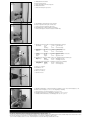
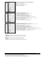
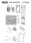
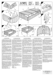
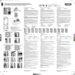
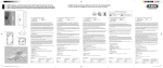
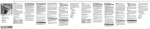
D Montage- und Bedienungsanleitung
für ABUS Fenster- und Türsicherung FTS 206
Achtung! für Falzstärken von 0 – 25 mm
Abb./fig./schéma / afb. / ill. 1
D Diese Anleitung ist wie folgt untergliedert:
I. Allgemeine Hinweise
IV. Werkzeug
II. Einsatzmöglichkeit
V. Montageanleitung
III. Packungsinhalt
VI. Bedienung
0 – 25
24
51
156
69
I.
Allgemeine Hinweise
Die FTS 206 ist nach DIN 18 104-1 und VdS 2536 anerkannt. Durch
DIN Certco ist FTS 206 zertifiziert „EINBRUCHHEMMEND DIN-geprüft“.
FTS 206 bietet zusätzlich Schutz gegen unberechtigtes Eindringen in
Räume. Gemäß DIN 18 104-1 wird empfohlen, dass pro 1 Meter
Fensterhöhe rechts und links jeweils eine Zusatzsicherung montiert wird
(pro Fenster). Polizei und Versicherer empfehlen dieses ebenfalls.
Die optimale Schutzwirkung wird erreicht, wenn entsprechend dieser
Montage- und Bedienungsanleitung vorgegangen wird.
Die Befestigungsschrauben sollten zur Vermeidung von Überdrehung
mit einem geeigneten Werkzeug eingeschraubt und von Hand angezogen
werden. Ausschließlich ABUS-Befestigungsmaterial einsetzen.
Für eventuell auftretende Verletzungen bzw. Schäden, die bei der Montage
und/oder durch unsachgemäße Handhabung entstehen, übernimmt der
Hersteller keine Haftung!
Ein Zugang des gesamten Objektes muss von außen mittels Schlüssel
zu öffnen sein.
II. Einsatzmöglichkeit
FTS 206 wird auf der Griffseite des Fensters oder der Fenstertür montiert
und eignet sich für alle gängigen nach innen öffnende Fenster/
Fenstertüren mit Dreh- oder -Dreh-Kipp-Beschlägen (Abb. 1).
Die Montage kann auf den Werkstoffen Kunststoff, Holz oder Alu erfolgen.
Die Fenster/Fenstertüren können nach rechts oder links öffnen.
Wahlweise kann die Betätigung der FTS 206 von oben oder unten erfolgen.
Die Montage ist für Betätigung von unten beschrieben.
FTS 206 wird grundsätzlich auf der Innenseite montiert, das Flügelblech
auf dem Fensterflügel und die Rahmenleiste auf dem Rahmen.
Bei schlechten Befestigungsmöglichkeiten (weicher, hohler oder ausgeschäumter Untergrund und Kunststofffenster mit und ohne Metalleinlage
und Holzfenster) und/oder guten Angriffsmöglichkeiten von außen,
sollten mehr Sicherungen und zusätzlich Befestigungsmittel
(Verbundmörtel oder Befestigungsanker) eingesetzt werden.
Hierzu verwenden Sie bitte den ABUS-Befestigungsanker BA oder
alternativ bei Kunststoffrahmen das ABUS-Befestigungsset IM 100.
Zu IM 100 benötigen Sie einen geeigneten Verbundmörtel,
z.B. der Marke Fischer FIS VS 150C oder ein ähnliches Produkt.
ABUS BA und ABUS IM 100 sowie Verbundmörtel sind im Handel erhältlich.
Die in Abb. 2 zusätzlich gezeigten ABUS-Produkte (FAS) sind auch im
Handel erhältlich.
Abb./fig./schéma / afb. / ill. 2
FTS
FAS
FTS
III. Packungsinhalt (Abb. 3)
11. 1 Rahmenleiste
12. 1 Führungshülse
13. 1 Druckstift
14. 1 Clip
15. 1 Riegelbolzen
16. 1 Feder
17. 1 Flügelblech
18. 1 Flügelhaube
19. 1 Rahmenhaube
10. Schrauben:
1 Stück 5,5 x 50 mm
2 Stück 3,5 x 25 mm
2 Stück 4,8 x 50 mm
3 Senkschrauben 4,8 x 50 mm
2 Stück 3,5 x 13 mm
1 Senkschrauben 4,8 x 22 mm
11. 1 Satz Unterlagen für Flügelblech je 1x 1, 2, 3, 4, 8 mm
12. 1 Satz Unterlagen für Rahmenleiste je 1x 1, 2, 4 mm
FAS
FTS
FAS
FTS
IV. Montagewerkzeug
Kreuzschlitzschraubendreher
Bohrmaschine
Metermaß
Feile, Säge zum Kürzen der Schrauben, ggf. Schraubstock
6
12
8
9
5
10
Bohrtabelle
für
Schrauben
Ø
In Holz und Kunststoff
ohne Metalleinlage
Bohrer Ø
In Alu und Kunststoff
mit Metalleinlage
Bohrer Ø
5,5 mm
4,0 mm
4,5 mm
4,8 mm
3,5 mm
3,5 mm
3,5 mm
2,5 mm
3,0 mm
11
3
D V. Montageanleitung:
4
2
Abb./fig./schéma / afb. / ill. 3
1
7
Wichtige Hinweise:
1. Vor der Montage prüfen Sie bitte die Einstellung des Fensters.
Stellen Sie sicher, dass sich das Fenster/die Fenstertür einwandfrei
öffnen und schließen lässt.
2. Messen Sie auch nach, ob die in Abb. 1 angegebenen Mindestmaße an Ihrem Fenster/Ihrer Fenstertür vorhanden sind.
3. Die Bohrlochtiefen bzw. die Schraubenlängen müssen auf die
örtlichen Gegebenheiten abgestimmt werden.
4. Austreten des Bohrers bzw. der Schrauben auf der Rückseite
vermeiden! Ggf. mit Bohranschlag arbeiten oder die vorhandenen
Schrauben kürzen. Beim Bohren keine beweglichen Teile, Dichtungen
oder Glasscheiben verletzen.
G Installation and operation instructions
for ABUS window and door lock FTS 206
Important! for rabbet thicknesses of 0 – 25 mm
F Instructions de montage
pour verrou ABUS FTS 206
Attention! pour des épaisseurs de plis de 0 à 25 mm
G These instructions are organised in the following sections:
I. General instructions
IV. Tools
II. Possible uses
V. Installation instructions
III. Pack contents
VI. Operation
F Ce manuel comporte les chapitres suivants:
I. Conseils d’ordre général
IV. Outillage
II. Application
V. Instructions d’installation
III. Liste de colisage
VI. Utilisation
I.
I.
General instructions
The FTS 206 is recognised as complying with the strict test requirements
of DIN 18 104-1 and VdS 2536.
FTS 206 is certified by DIN Certco as “BURGLAR RETARDANT DIN tested”.
FTS 206 offers additional protection from unauthorised intruders in your
rooms. DIN 18 104-1 recommends that an additional security device
should be fitted on the left and right for every meter in height (per window).
The police and insurance companies also give the same recommendation.
Optimum protection can be achieved by proceeding according to these
installation and operation instructions. To prevent the risk of overtightening, the fastening screws should by screwed in using a suitable tool and
tightened by hand. Only use ABUS fastening material.
The manufacturer does not assume any liability for possible injuries
or damages caused during installation and/or by incorrect handling!
II. Possible uses
FTS 206 is mounted on the handle side of the window or French door
and is suitable for all common windows/French doors opening
to the inside with turn or turn-and-tilt hardware (fig. 1).
The lock can be fitted to wood, PVC or aluminium.
The windows/French doors can open to the right or left.
The security device FTS 206 can be activated from top or bottom.
The described installation procedure is for activation from the bottom.
FTS 206 is always mounted to the inside, with the casement plate on the
window casement and the frame strip on the frame.
In poor fixture conditions (soft or hollow or foam base and PVC windows
with and without metal inlay and wooden windows) and/or good
possibilities for intrusion from the outside, more security devices and
additional fastenings should be used (composite mortar or fixing bolts).
To do so, please use the ABUS fixing bolt BA or alternatively for PVC
frames, the ABUS fastening set IM 100. For IM 100 you need a suitable
composite mortar, e.g. Fischer FIS VS 150C or similar. ABUS BA and
ABUS IM 100 are available from retail stores together with composite
mortar.
The ABUS products (FAS) shown in fig. 2 are also available from retail
stores.
III. Pack contents (fig. 3)
11.
12.
13.
14.
15.
16.
17.
18.
19.
10.
1 frame strip
1 guide sleeve
1 pressure pin
1 clip
1 locking bolt
1 spring
1 casement plate
1 casement cover
1 frame cover
Screws:
1 each 5.5 x 50 mm
2 each 3.5 x 25 mm
2 each 4.8 x 50 mm
3 countersunk screws 4.8 x 50 mm
2 each 3.5 x 13 mm
1 countersunk screws 4.8 x 22 mm
11. 1 set of shims for casement plate, 1x 1, 2, 3, 4, 8 mm each
12. 1 set of shims for frame strip, 1x 1, 2, 4 mm each
Conseils d’ordre général
La FTS 206 satisfait aux exigences de contrôle sévères des normes
DIN 18 104-1 et VdS 2536. Le certificat DIN indique que FTS 206
a obtenu la qualification «anti-effraction DIN».
FTS 206 offre en plus une protection contre les intrusions par effraction
dans votre logement. Selon la norme DIN 18 104-1, il est recommandé
de monter une sécurité complémentaire par mètre de hauteur de fenêtre,
à gauche comme à droite. La police et les compagnies d’assurance le
recommandent également. Pour un effet de protection optimal, suivez les
instructions de ce manuel d’installation et d’utilisation. Afin d’éviter un
serrage abusif, vissez et serrez les vis de fixation à la main et avec un
outillage adéquat. Utilisez exclusivement des accessoires ABUS.
Le fabricant n’assume aucune responsabilité pour d’éventuels blessures
ou dégâts causés pendant l’installation et/ou par suite de manipulations
inappropriées! L’ensemble doit être accessible de l’extérieur afin de l’ouvrir
au moyen d’une clé.
II. Application
FTS 206 est monté sur le côté paumelles de la fenêtre ou de la portefenêtre et convient pour toutes les fenêtres/portes-fenêtres courantes,
ouvrant vers l’intérieur et pourvues de quincaillerie battante ou oscillobattante avec commande d’une seule main (schéma 1).
L’installation peut être effectuée sur des cadres en bois, en PVC ou en
aluminium. Les fenêtres/portes-fenêtres peuvent s’ouvrir à gauche ou
à droite. La commande de FTS 206 peut être effectuée par le haut ou par
le bas. L’installation décrite correspond à une commande par le bas.
FTS 206 est monté en principe du côté intérieur, la platine d’ancrage sur
l’ouvrant et le socle de fixation sur le dormant.
En cas de possibilités de fixation défavorables (fenêtres en boîs ou en
PVC), plusieurs sécurités et des fixations supplémentaires (ancre de
fixation ou mortier) doivent être prévues.
Pour cela, utilisez les ancres de fixation ABUS BA (pour fenêtres en PVC,
en bois ou en aluminium) ou l’ensemble de fixations ABUS IM 100
(pour fenêtres en PVC).
Pour IM 100, un mortier approprié est requis, par exemple FIS VS 150C
de la marque Fischer, HFX de la marque Hilti ou un produit similaire.
ABUS BA et ABUS IM 100 ainsi que le mortier de fixation sont disponibles
dans le commerce.
Les produits ABUS complémentaires illustrés en schéma 2 (FAS) sont
également disponibles dans le commerce.
III. Liste de colisage (schéma 3)
11. 1 socle de fixation
12. 1 tuyau de guidage
13. 1 tige d’appui
14. 1 circlip
15. 1 pêne de verrouillage
16. 1 ressort
17. 1 platine d’ancrage
18. 1 cache pour platine
19. 1 cache pour socle
10. Vis:
1 pièce de 5,5 x 50 mm
2 pièces de 3,5 x 25 mm
2 pièces de 4,8 x 50 mm
3 vis à tête conique de 4,8 x 50 mm
2 pièces de 3,5 x 13 mm
1 vis à tête conique de 4,8 x 22 mm
11. 1 ensemble d’entretoises pour platine d’ancrage chacun 1x 1, 2, 3, 4, 8 mm
IV. Installation tools
Phillips screwdriver
Drill
Yardstick
Saw, file for shortening the screws, possibly vice
12. 1 ensemble d’entretoises pour socle de fixation chacun 1x 1, 2, 4 mm
Drilling table
Tableau de perçage
IV. Outillage requis
Tournevis cruciforme
Perceuse
Mètre ruban
Lime, scie pour raccourcir les vis, tournevis
for
screws
Ø
in wood and PVC
without metal inlay
drill bit Ø
in aluminium and PVC
with metal inlay
drill bit Ø
pour
vis
de Ø
dans châssis bois et PVC
sans armature métallique
foret Ø
dans châssis aluminium et PVC
avec armature métallique
foret Ø
5.5 mm
4.0 mm
4.5 mm
5,5 mm
4,0 mm
4,5 mm
4.8 mm
3.5 mm
3.5 mm
4,8 mm
3,5 mm
3,5 mm
3.5 mm
2.5 mm
3.0 mm
3,5 mm
2,5 mm
3,0 mm
G V. Installation instructions:
• Before installation, please check the setting of the window
or French door.
• If necessary, readjust the fittings so that the window (French door)
opens and closes perfectly.
• Also check whether your window/French door complies with the
minimum dimensions shown in fig. 1.
• The depths of the drilled holes and screw lengths must be adjusted
to the local conditions.
• Avoid the drill or screws from coming out at the back!
Possibly work with drill stopper or shorten the existing screws.
• When drilling, do not damage any moving parts, seals or glass panes.
F V. Instructions d’installation:
Indications importantes:
• Avant l’installation, contrôlez l’ouverture de la fenêtre. Assurezvous que la fenêtre/porte-fenêtre ouvre et ferme parfaitement.
• Vérifiez si votre fenêtre/porte-fenêtre comporte les dimensions
minimales indiquées en schéma 1.
• Les profondeurs de perçage ou les longueurs de vis doivent être
adaptées aux conditions locales.
• Evitez le dépassement de perçage ou de vis sur la face arrière!
Le cas échéant, utilisez une butée de perçage ou raccourcissez
les vis de fixation.
• Lors du perçage, évitez d’endommager les éléments mobiles,
les joints ou les vitres.
n Montage- en bedieningsinstructie
voor ABUS opleggrendel FTS 206
Opgelet! voor sponningdiktes van 0 – 25 mm
I Istruzioni di montaggio ed uso della sicura
per finestre e porte FTS 206
Attenzione! per spessori di aggraffatura 0 – 25 mm
n Deze montage- en bedieningsinstructie is als volgt onderverdeeld:
I. Algemeen
IV. Gereedschap
II. Toepassing
V. Montage
III. Verpakkingsinhoud
VI. Bediening
I Queste istruzioni si suddividono nel modo seguente:
I. Istruzioni generali
IV. Attrezzi
II. Possibilità d’impiego
V. Istruzioni di montaggio
III. Contenuto della confezione
VI. Uso
I.
I.
Algemeen
FTS 206 voor naar binnen draaiende draai/kiep elementen.
FTS 206 is volgens keuringseisen NEN 5096 SKG gecertificeerd.
De FTS 206 biedt daarnaast bescherming tegen onbevoegd binnendringen van uw woning. Advies: monteer aan de scharnierzijde voor
maximale veiligheid 2 stuks per 1 meter raamhoogte.
Op kunststof zonder metalen kern dient u deze scharnierbeveiliger
in combinatie met ABUS BA bevestigingsanker te monteren.
Optioneel verkrijgbaar, zie voor montage in de handleiding van BA.
Optimale veiligheid wordt bereikt door nauwkeurig opvolgen van deze
montage- en gebruiksaanwijzing. Om overexpansie of doldraaien van de
bevestigingsschroeven te vermijden, draait u handmatig en met passend
gereedschap de schroeven vast.
Voor eventueel verwondingen en/of schade tijdens montage en/of
door ondeskundig gebruik ontstaan, aanvaardt de fabrikant geen
aansprakelijkheid!
II. Toepassing
De FTS 206 wordt aan de sluitzijde gemonteerd en is geschikt voor alle
naar binnen draaiende ramen en deuren met draai/kiep-beslag (afb. 1).
Montage mogelijk op hout, kunststof of aluminium. Rechts of links
draaiend. Hoewel de bediening van de vergrendeling van onder- of van
bovenaf plaats kan vinden wordt in deze montage- en bedieningsinstrictie
uitgegaan van een bediening van onderaf.
De FTS 206 wordt uitsluitend aan de binnenzijde gemonteerd;
de raamplaat op het raam of deur en de kozijnlijst op het kozijn.
Bij slechte bevestigingsmogelijkheden (zacht hout of kunststof)
dienen meerdere sloten en extra bevestigingsmiddelen
(bevestigings- of chemische ankers) toegepast te worden.
Hiervoor kunt u het ABUS bevestigingsanker BA (zacht hout,
kunststof, aluminium) of als alternatief de ABUS bevestigingsset
IM 100 (kunststof) gebruiken (in schroefgat D).
Bij IM 100 heeft u een passend chemisch anker nodig, bijv.
Fischer FIS VS 150C, Hilti HFX of vergelijkbaar.
ABUS BA, IM 100 en chemische ankers zijn in de handel verkrijgbaar.
De in afb. 2 extra getoonde ABUS producten (FAS) zijn eveneens in de
handel verkrijgbaar.
III. Verpakkingsinhoud (afb. 3)
11. 1 kozijnlijst
12. 1 geleidingshuls
13. 1 drukstift
14. 1 clip
15. 1 vergrendelingspen
16. 1 veer
17. 1 raamplaat
18. 1 raamplaat-afdekkap
19. 1 kozijnlijst-afdekkap
10. Schroeven:
1 stuks 5,5 x 50 mm
2 stuks 3,5 x 25 mm
2 stuks 4,8 x 50 mm
3 stuks 4,8 x 50 mm met verzonken kop
2 stuks 3,5 x 13 mm
1 stuks 4,8 x 22 mm met verzonken kop
11. 1 set opvulplaatjes voor raamplaat 1x 1, 2, 3, 4 en 8 mm
12. 1 set opvulplaatjes voor kozijnlijst 1x 1, 2 en 4 mm
IV. Gereedschap
Kruiskopschroevendraaier
Boormachine
Meetlat
Zaag, vijl en eventueel bankschroef voor het inkorten van de schroeven
Boortabel
Istruzioni generali
La FTS 206 è conforme ai severi requisiti di controllo della DIN 18 104-1
e della VdS 2536.
Con la DIN Certco essa è certificata come «ANTISCASSO conf. DIN».
La FTS 206 garantisce una protezione in più a difesa della Vostra casa.
Secondo DIN 18 104-1 si consiglia di montare per ogni metro di altezza
della finestra, una sicura supplementare sul lato destro e una sul lato
sinistro (per ogni finestra). Anche la polizia e le compagnie d’assicurazione
consigliano tali misure.
Si può ottenere una protezione ottimale, procedendo secondo queste
istruzioni di montaggio ed uso. Le viti di fissaggio, per evitarne un
serraggio eccessivo, devono essere avvitate con un utensile adatto
e poi serrate a mano.
Impiegare esclusivamente materiale di fissaggio ABUS.
Per eventuali ferimenti e/o danni, che si verificano durante il montaggio
e/o per maneggio indebito, il produttore non si assume alcuna
responsabilità!
II. Possibilità d’impiego
La FTS 206 viene montata sul lato della finestra o porta-finestra su cui
si trova la maniglia ed è adatta per tutte le normali finestre e portefinestre che si aprono verso l’interno, con guarnizioni metalliche
girevoli o girevoli- a bilico (ill. 1).
Si può montare la FTS 206 su legno, plastica o alluminio.
Le finestre/porte-finestre possono aprirsi verso destra o verso sinistra.
A scelta la FTS 206 si può azionare dall’alto o dal basso.
Il montaggio è descritto per azionamento dal basso.
Di solito la FTS 206 viene montata all’interno, la lamiera del battente
sul battente della finestra ed il listello del telaio sul telaio.
Se le possibilità di fissaggio sono scadenti (sottofondo morbido o vuoto
o riempito con espanso e finestre in plastica con o senza inserto metallico
e finestre in legno) e le possibilità di effrazione dall’esterno sono buone,
si dovrebbero utilizzare più sicure e mezzi di fissaggio supplementari
(malta o bullone di fissaggio).
Allo scopo utilizzare per favore il bullone di fissaggio ABUS BA o come
alternativa, nel caso di telai in plastica, il kit di fissaggio ABUS IM 100.
Per lo IM 100 serve una malta adatta, p.e. della marca Fischer FIS VS 150C
o un prodotto simile. ABUS BA e ABUS IM 100 come anche la malta si
possono acquistare.
Anche i prodotti ABUS (FAS) raffigurati nell’ill. 2 si possono acquistare.
III. Contenuto della confezione (ill. 3)
11. listello del telaio
12. boccola di guida
13. 1 perno di spinta
14. 1 clip
15. 1 perno del chiavistello
16. 1 molla
17. 1 lamierina (per battente)
18. 1 coperchietto della lamierina per battente
19. 1 coperchietto per listello del telaio
10. Viti:
1 vite da 5,5 x 50 mm
2 viti da 3,5 x 25 mm
2 viti da 4,8 x 50 mm
3 viti a testa svasata da 4,8 x 50 mm
2 viti da 3,5 x 13 mm
3 viti a testa svasata da 4,8 x 22 mm
11. 1 kit di spessori per ogni lamierina del battente,
ciascuno 1 x 1, 2, 3, 4, 8 mm
12. 1 kit di spessori per ogni listello del telaio ciascuno 1x 1, 2, 4 mm
IV. Attrezzi da montaggio
Cacciavite a stella (con punta magnetica)
Trapano
Sega, lima per accorciare le viti, in caso una morsa
Tabella di trapanazioni
voor
schroeven
Ø
in hout en kunststof
zonder metalen kern
boor Ø
in aluminium en kunststof
met metalen kern
boor Ø
per
viti
Ø
in legno e plastica
senza inserto metallico
punta da trapano Ø
in alluminio e plastica
con inserto metallico
punta da trapano Ø
5,5 mm
4,0 mm
4,5 mm
5,5 mm
4,0 mm
4,5 mm
4,8 mm
3,5 mm
3,5 mm
4,8 mm
3,5 mm
3,5 mm
3,5 mm
2,5 mm
3,0 mm
3,5 mm
2,5 mm
3,0 mm
n V. Montage:
Belangrijke aanwijzingen:
1. Voor de montage dient u de afstelling van het raam resp.
de deur te controleren.
Zorg ervoor dat het raam / de deur probleenloos geopend
en gesloten kan worden.
2. Meet na of de in afb. 1 aangegeven min. afmetingen
daadwerkelijk beschikbaar zijn.
3. De boordieptes en schroeflengten moeten aan het gevelelement
aangepast worden.
4. Voorkom doorboren en -schroeven.
Eventueel met een booraanslag werken of de schroeven inkorten.
Bij het boren geen beslag, afdichtingen of ruiten beschadigen.
I V. Istruzioni per il montaggio:
Avvertenze importanti:
• Prima del montaggio verificare per favore la regolazione della finestra
risp. della porta finestra.
• Se necessario registrare nuovamente i ferramenti affinché la finestra
(la porta-finestra) si chiuda e si apra perfettamente.
• Verificare anche che le misure minime indicate nell’ill. 1 esistano
nelle vostre finestre/porte-finestre.
• Le profondità per trapanare i fori, risp. le lunghezze delle viti devono
essere adattate alle condizioni particolari.
• Evitare che la punta del trapano risp. la vite fuoriesca dall’altra parte!
Se necessario lavorare con arresto del trapano o accorciare le viti.
• Quando si trapana, non danneggiare parti mobili, guarnizioni o vetri.
Montage / Installation / Installation / Montage / Montaggio
3 mm
D Rahmenleiste positionieren. Bohrlöcher A + B anzeichnen.
> 3 mm < Abstand.
Hilfsmittel: Unterlage für Rahmenleiste 2 mm einschließlich Nocken = 3 mm.
G Position frame batten. Mark drill holes A + B.
> 3 mm < distance.
Accessories: Base for frame batten 2 mm including pins = 3 mm.
F Positionner la lisière du cadre. Dessiner les trous de perçage A + B.
> 3 mm < ecart.
Aide: Support pour la lisière du cadre 2 mm, stries incluses = 3 mm.
n Kader plaatsen. Boorgaten A + B markeren.
> 3 mm < afstand.
Hulpmiddel: Ondergrond voor kader 2 mm inclusief kam = 3 mm.
I Posizionare la cornice del telaio. Segnare i fori A + B.
Distanza > 3 mm <.
Ausilio: Spessore per cornice del telaio 2 mm compresa camma = 3 mm.
B
A
B
Abb. / fig.
schéma
afb. / ill. 1
D Löcher A + B vorbohren (Holz und Kunststoff ohne Metalleinlage).
In Alu und Kunststoff mit Metalleinlage siehe Bohrtabelle.
G Pre-drill holes A + B (wood and plastic without metal ply).
In aluminium and plastic with metal ply see drilling chart.
F Préforer les trous A + B (bois ou plastique insertion en métal).
Dans se l’alu et du plastique avec insertion en métal, voir tableau de perçage.
n Gaten A + B voorboren (hout en kunststof zonder metalen versterking).
In alu en kunststof met metalen versterking, zie boortabel.
I Sbozzare i fori A + B (legno e plastica senza inserto metallico).
In caso di alluminio e plastica con inserto metallico vedi la tabella di foratura.
B Ø 3,5
A Ø 4,0
B Ø 3,5
Abb. / fig.
schéma
afb. / ill. 2
D Rahmenleiste eventuell mit Kunststoffunterlagen ausgleichen.
Bei Falzdicke:
18 mm
19 mm = 1 mm Unterlage
keine
Unterlage
25 mm = 7 mm Unterlage
G If need be compensate for frame batten with plastic underlays.
With rabbet
18 mm
19 mm = 1 mm underlay
thickness:
no
underlay
25 mm = 7 mm underlay
F Egaliser la lisière du cadre, éventuellement avec un support en plastique.
Pour une
18 mm
19 mm = support de 1 mm
épaisseur
pas de
de plis:
support
25 mm = support de 7 mm
n Kader eventueel effenen met onderlaag in kunststof.
Bij sponning18 mm
19 mm = onderlaag van 1 mm
dikte:
geen
onderlaag
25 mm = onderlaag van 7 mm
I Eventualmente equilibrare la cornice del telaio con spessori di plastica.
Con spessore
18 mm
19 mm = 1 mm di spessore
dell’aggraffatura: nessuno
spessore
25 mm = 7 mm di spessore
Abb. / fig.
schéma
afb. / ill. 3
Abb. / fig.
schéma
afb. / ill. 4
4,8 x 50
D
G
F
n
I
Rahmenleiste anschrauben
Screw on frame batten
Viser la lisiére du cadre
Kader vastschroeven
Avvitare la cornice del telaio
D
G
F
n
I
Druckstifteinheit falls demontiert wieder vormontieren.
If pressure pin unit disassembled pre-assemble again.
Prémonter l’ensemble de chevilles de pression, s’il a été démonté.
Indien de drukstift gedemonteerd werd, ze opnieuw monteren.
Se smontata, premontare l’unità del perno a pressione.
5,5 x 50
4,8 x 50
Abb. / fig. / schéma / afb. / ill. 5
ABUS - Das gute Gefühl der Sicherheit
D
G
F
n
I
Technische Änderungen vorbehalten. Für Irrtümer und Druckfehler keine Haftung. ABUS © 2006
Subject to technical alterations. No liability for mistakes and printing errors. ABUS © 2006
Nous nous réservons le droit de toutes modifications techniques. Nous n’assumons aucune responsabilité pour des erreurs ou défauts d’impression éventuels. ABUS © 2006
Technische wijzigingen voorbehouden. Geen aansprakelijkheid voor vergissingen en drukfouten. ABUS © 2006
Ci si riservano modifiche tecniche. Per errori e refusi di stampa non ci si assume alcuna responsabilità. ABUS © 2006
www.abus.com
390256 9/06
ca.
40
mm
Abb. / fig.
schéma
afb. / ill. 6
Abb. / fig.
schéma
afb. / ill. 7
Druckstifteinheit einschieben.
Push in pressure pin unit.
Insérer l’ensemble des chevilles de pression.
Druckstift inschuiven.
Inserire l’unità del perno a pressione.
D
G
F
n
I
Clip aufdrücken (muss auf beiden Seiten einrasten).
Press on clip (must lock into place on both sides).
Pousser le clip (doit verrouiller des deux côtés).
Clip indrukken (moet aan beide kanten ineensluiten).
Premere sulla clip (deve arrestarsi a scatto da entrambi i lati).
D Flügelblech positionieren, dabei evtl. mit Kunststoffunterlagen unterlegen.
Bei Falzdicke:
17 mm
16 mm = 1 mm Unterlage
keine
Unterlage
0 mm = 17 mm Unterlage
G Position casement plate, underlaying with plastic underlays if necessary.
With rabbet
17 mm
16 mm = 1 mm underlay
thickness:
no
underlay
0 mm = 17 mm underlay
F Positionner la tôle pliée, glisser éventuellement un support en plastique en dessous.
Pour une
17 mm
16 mm = support de 1 mm
épaisseur
pas de
de plis:
support
0 mm = support de 17 mm
n Vleugelpaneel positioneren, daarbij eventueel een onderlaag in kunststof aanbrenegen.
Bij sponning17 mm
16 mm = onderlaag van 1 mm
dikte:
geen
onderlaag
0 mm = onderlaag van 17 mm
I Posizionare la lamiera a battente, eventualmente inserire spessori di plastica.
Con spessore
17 mm
16 mm = 1 mm di spessore
dell’aggraffatura: nessuno
spessore
0 mm = 17 mm di spessore
Abb. / fig.
schéma
afb. / ill. 8
Löcher „C“
anzeichnen
Mark holes
“C”
Dessiner
les trous «C»
Gaten „C”
markeren
Segnare
i fori «C»
D
G
F
n
I
C
Abb. / fig.
schéma
afb. / ill. 9
D
G
F
n
I
Löcher „C“ vorbohren.
Pre-drill holes “C”.
Prépercer les trous «C».
Gaten „C” voorboren.
Sbozzare i fori «C».
D
G
F
n
I
Flügelblech anschrauben, eventuell mit Unterlagen. Schrauben 3,5 x 13 oder je nach Unterlagen 3,5 x 25.
Screw on casement plate, 3.5 x 13 or 3.5 x 25 depending on underlays.
Visser la tôle pliée, en fonction du support 3,5 x 13 ou 3,5 x 25.
Vleugelpaneel vastschroeven, naargelang de onderlagen 3,5 x 13 of 3,5 x 25.
Avvitare la lamiera a battente, a seconda degli spessori 3,5 x 13 o 3,5 x 25.
C
Ø 2,5
Abb. / fig.
schéma
afb. / ill. 10
C
www.abus.com
D
G
F
n
I
Technische Änderungen vorbehalten. Für Irrtümer und Druckfehler keine Haftung. ABUS © 2006
Subject to technical alterations. No liability for mistakes and printing errors. ABUS © 2006
Nous nous réservons le droit de toutes modifications techniques. Nous n’assumons aucune responsabilité pour des erreurs ou défauts d’impression éventuels. ABUS © 2006
Technische wijzigingen voorbehouden. Geen aansprakelijkheid voor vergissingen en drukfouten. ABUS © 2006
Ci si riservano modifiche tecniche. Per errori e refusi di stampa non ci si assume alcuna responsabilità. ABUS © 2006
Abb. / fig.
schéma
afb. / ill. 11
Abb. / fig.
schéma
afb. / ill. 12
D
D
G
F
n
I
Funktion überprüfen, dazu Fenster öffnen und schließen, eventuell Flügelblech nachjustieren.
Check that it functions by opening and closing window, perhaps readjusting casement plate.
Contrôler le functionnement, ouvrir et fermer la fenêtre, ajuster éventuellement la tôle pliée.
De werking controleren: daartoe opent en sluit u het venster, en past u de vleugelpaneel eventueel aan.
Controllare il funzionamento, a tale scopo chiudere e aprire la finestra, eventualmente regolare la lamiera a battente.
D
G
F
n
I
Löcher „D“ vorbohren (bei D1 Fensterbeschlag nicht beschädigen).
Pre-drill holes “D” (with D1 do not damage window fitting).
Prépercer les trous «D» (pour D1 ne pas endommager la garniture de la fenêtre).
Gaten „D” voorboren (bij D1 vensterbeslag niet beschadigen).
Sbozzare i fori «D» (con D1 non danneggiare la ferramenta della finestra).
D
G
F
n
I
Flügelblech anschrauben (bei umlaufendem Beschlag D1 = 4,8 x 22).
Screw on casement plate (with continuous fitting D1 = 4.8 x 22).
Visser la tôle pliée (pour garniture d’une circonférence de D1 = 4,8 x 22).
Vleugelpaneel vastschroeven (bij beslag rondom D1 = 4,8 x 22).
Avvitare la lamiera a battente (con ferramenta perimetrale D1 = 4,8 x 22).
D
G
F
n
I
Rahmenhaube aufsetzen.
Put frame cover in place.
Poser l’armature du cadre.
Kaderkast opzetten.
Montare la scossalina del telaio.
D
G
F
n
I
Flügelhaube aufsetzen.
Put casement cover in place.
Poser l’armature «ailée».
Vleugelkast opzetten.
Montare la scossalina del battente.
D1
D
Ø 3,5
Abb. / fig.
schéma
afb. / ill. 13
D 4,8 x 50
D1
4,8x50
(22)
D 4,8 x 50
Abb. / fig.
schéma
afb. / ill. 14
Abb. / fig.
schéma
afb. / ill. 15
www.abus.com
D
G
F
n
I
Technische Änderungen vorbehalten. Für Irrtümer und Druckfehler keine Haftung. ABUS © 2006
Subject to technical alterations. No liability for mistakes and printing errors. ABUS © 2006
Nous nous réservons le droit de toutes modifications techniques. Nous n’assumons aucune responsabilité pour des erreurs ou défauts d’impression éventuels. ABUS © 2006
Technische wijzigingen voorbehouden. Geen aansprakelijkheid voor vergissingen en drukfouten. ABUS © 2006
Ci si riservano modifiche tecniche. Per errori e refusi di stampa non ci si assume alcuna responsabilità. ABUS © 2006
Abb. / fig.
schéma
afb. / ill. 16
Abb. / fig.
schéma
afb. / ill. 17
Abb. / fig.
schéma
afb. / ill. 18
VI. Bedienung / Operation / Utilisation / Bediening / Uso
D
G
F
n
I
Stufe 0
Stage 0
Niveau 0
Stand 0
Livello 0
= Fenstersicherung geöffnet.
= Window security device open.
= Dispositif de sécurité pour fenêtre ouverte.
= Vensterbeveiliging geopend.
= Sicurezza finestra aperta.
D Stufe 1 = Fenstersicherung verriegelt, öffnen ohne Schlüssel.
Druckstift bis zur ersten Rastung eindrücken.
Zum Öffnen Druckstift wieder bis zur ersten Rastung eindrücken und loslassen.
G Stage 1 = window security device locked, open without key.
Press pressure pin in until the first catch.
To open, press pressure pin in again to the first catch and release.
F Niveau 1 = Dispositif de sécurité pour fenêtre verrouillée, à ouvrir sans clef.
Pousser la cheville de pression jusqu’au premier verrouillage.
Pour ouvrir, pousser la cheville de pression à nouveau jusqu’au premier verrouillage et la lâcher.
n Stand 1 = Vensterbeveiliging vergrendeld openen zonder sleutel.
Duw de drukstift in tot de eerste inkeping.
Om te openen moet u de drukstift opnieuw indrukken tot de eerste inkeping en vervolgens loslaten.
I Livello 1 = Sicurezza finestra bloccata, apertura senza chiave.
Premere il perno fino alla prima tacca.
Per aprire premere di nuovo il perno fino alla prima tacca e poi rilasciare.
D Stufe 2 = Fenstersicherung verriegelt, öffnen nur mit Schlüssel möglich.
Druckstift bis zur zweiten Rastung eindrücken.
Zum Öffnen Schlüssel drehen, anschließend Druckstift bis zur ersten Rastung eindrücken und loslassen.
G Stage 2 = window security device locked, can be opened with key.
Press pressure pin in until second catch.
To open, turn key then press pressure pin in to the first catch and release.
F Niveau 2 = Dispositif de sécurité pour fenêtre verrouillée, à ouvrir sans une clef.
Pousser la cheville de pression jusqu’au deuxième verrouillage.
Pour ouvrir, tourner la clef, ensuite pousser la cheville de pression jusqu’au deuxième verrouillage et la lâcher.
n Stand 2 = Vensterbeveiliging vergrendeld, openen is enkel mogelijk met sleutel.
Duw de drukstift in tot de tweede inkeping.
Om te openen moet u aan de sleutel draaien, vervolgens de drukstift tot de eerste inkeping indrukken en daarna loslaten.
I Livello 2 = Sicurezza finestra bloccata, l’apertura è possibile esclusivamente con la chiave.
Premere il perno fino alla seconda tacca.
Per aprire girare la chiave, poi premere il perno fino alla prima tacca e rilasciare.
D Empfehlung:
Druckstift von Verriegelungsstufe 0 ohne Unterbrechung direkt in Verriegelungsstufe 2 eindrücken.
G Recommendation:
Druckstift von Verriegelungsstufe 0 ohne Unterbrechung direkt in Verriegelungsstufe 2 eindrücken.
F Conseil:
Pousser la cheville de pression directement et sans interruption, du niveau 0 au niveau 2.
n Aanbeveling:
Duw de drukstift zonder onderbreking direct van vergrendelstand 0 in vergrendelstand 2.
I Consiglio:
Premere il perno dal livello di bloccaggio 0 senza interruzione direttamente nel livello di bloccaggio 2.
www.abus.com
D
G
F
n
I
Technische Änderungen vorbehalten. Für Irrtümer und Druckfehler keine Haftung. ABUS © 2006
Subject to technical alterations. No liability for mistakes and printing errors. ABUS © 2006
Nous nous réservons le droit de toutes modifications techniques. Nous n’assumons aucune responsabilité pour des erreurs ou défauts d’impression éventuels. ABUS © 2006
Technische wijzigingen voorbehouden. Geen aansprakelijkheid voor vergissingen en drukfouten. ABUS © 2006
Ci si riservano modifiche tecniche. Per errori e refusi di stampa non ci si assume alcuna responsabilità. ABUS © 2006